acc. - opt - accessories and options acc1 acc3 acc4
TRANSCRIPT

U1
Industrial
U
GSM_mod.CT03 IGBD 0.1RX
Series
ACC. - OPT - ACCESSORIES AND OPTIONS
ACC4-R ACC4ACC4 - Accessori -Vaso Espansione
ACC4 - Accessories -Exspansion tank
ACC4 - Zübehor -Expansionsfäß U11
ACC5-R ACC5ACC5 - Accessori -sistema conscambiatore
ACC5 - Accessories - CoolingUnit
ACC5 - Zübehor -Kühlanlage U14
ACC6-RACC6
ACC6 - Accessori -Lubrificazione Forzata -BEARING
ACC6 - Accessories - Forcedlubrification - BEARING
ACC6 - Zübehor -Zwangsschiemierung -BEARING
U22
ACC6AACC6A - Accessori -Lubrificazione Forzata -GEAR
ACC6A - Accessories -Forced lubrification - GEAR
ACC6A - Zübehor -Zwangsschiemierung -GEAR
U26
ACC7-R
Hydraulic accessories ACC7A Accessori idraulici -Vibration Sensor
Hydraulic accessories -Vibration Sensor
Hydraulikzubehör - VibrationSensor U28
ACC7B Accessori idraulici -Vibration SWITCH
Hydraulic accessories -Vibration SWITCH
Hydraulikzubehör - VibrationSWITCH U29
ACC7C Accessori idraulici -FILLING
Hydraulic accessories -FILLING
Hydraulikzubehör - FILLING U30
ACC7D Accessori idraulici -PARTICLE MAGNETIC
Hydraulic accessories -PARTICLE MAGNETIC
Hydraulikzubehör -PARTICLE MAGNETIC U31
ACC7E Accessori idraulici -DRAIN
Hydraulic accessories -DRAIN
Hydraulikzubehör - DRAIN U32
ACC7F Accessori idraulici -BREATHER
Hydraulic accessories -BREATHER
Hydraulikzubehör -BREATHER U33
ACC7G Accessori idraulici -LEVEL
Hydraulic accessories -LEVEL
Hydraulikzubehör - LEVEL U34
ACC7H Accessori idraulici -HEATER
Hydraulic accessories -HEATER
Hydraulikzubehör - HEATER U35
ACC7I1Accessori idraulici -TEMPERATURESENSOR
Hydraulic accessories -TEMPERATURE SENSOR
Hydraulikzubehör -TEMPERATURE SENSOR U36
ACC7I2Accessori idraulici -TEMPERATURESWITCH
Hydraulic accessories -TEMPERATURE SWITCH
Hydraulikzubehör -TEMPERATURE SWITCH U27
ACC7I3Accessori idraulici -TEMPERATURETERMOWELL
Hydraulic accessories -TEMPERATURETERMOWELL
Hydraulikzubehör -TEMPERATURETERMOWELL
U38
ACC7L Accessori idraulici -FILTER
Hydraulic accessories -FILTER
Hydraulikzubehör - FILTER U39
ACC7M1 Accessori idraulici -PRESSURE SENSOR
Hydraulic accessories -PRESSURE SENSOR
Hydraulikzubehör -PRESSURE SENSOR U40
ACC7M2 Accessori idraulici -PRESSURE SWITCH
Hydraulic accessories -PRESSURE SWITCH
Hydraulikzubehör -PRESSURE SWITCH U41
ACC7M3Accessori idraulici -PRESSURE Differentialgauge
Hydraulic accessories -PRESSURE Differentialgauge
Hydraulikzubehör -PRESSURE Differentialgauge
U42
ACC7N1 Accessori idraulici -FLOW SENSOR
Hydraulic accessories - FLOWSENSOR
Hydraulikzubehör - FLOWSENSOR U43
ACC7N2 Accessori idraulici -FLOW SWITCH
Hydraulic accessories - FLOWSWITCH
Hydraulikzubehör - FLOWSWITCH U44
ACC7N3 Accessori idraulici -FLOW VISUAL
Hydraulic accessories - FLOWVISUAL
Hydraulikzubehör - FLOWVISUAL U45
ACC7O Accessori idraulici -COOL
Hydraulic accessories - COOL Hydraulikzubehör - COOL U47
ACC7P Accessori idraulici -LEVEL-BREATHER
Hydraulic accessories -LEVEL-BREATHER
Hydraulikzubehör -LEVEL-BREATHER U48
ACC7Z Accessori idraulici -GENERIC
Hydraulic accessories -GENERIC
Hydraulikzubehör -GENERIC U49
ACC8-RACC8 ACC8 - Accessori - Tipo
TenuteACC8 - Accessories - SealType
ACC8 - Zübehor - Typ vonDichtung U51
ACC8AAccessori - Static SealCOMPOUND
Accessories - Static SealCOMPOUND
Zubehör - Static SealCOMPOUND U55
OPT OPTOPT - Opzioni -Materiale degli anelli ditenuta
OPT - Options - Materials ofSeals
OPT - Optionen -Dichtungsstoffe U56
ACC9-R
ACC9A Accessori generali -Coperchio di ispezione
Accessories custom-Inspection Cover
Zübehor custom -Inspektionsdeckel U59
ACC9B Accessori generali -Flangia freno
Accessories custom -Brake Flange
Zübehor custom -Bremsflansch U59
ACC9C Accessori generali -Base motore
Accessories custom -Motor Mount
Zübehor custom -Motorbasis U61
ADDITIONAL SHAFT EXTENSIONS U63
GEAR SHIFT U66
ACC1-R ACC1ACC1 - Accessori-Estremità uscita
ACC1 - Accessories - OutputEnd
ACC1 - Zubehör -Abtriebswellenenden U2
ACC3-R ACC3ACC3 - Accessori -Versioni pendolari
ACC3 - Accessories - ShaftMounted Versions
ACC3 - Zubehör -Aufsteckversionen U5

U2
Industrial
GSM_mod.CT03 IGBD 0.1RX
Series
FF.
ACC1 ACC1 - Accessori-Estremità uscita
ACC1 - Accessories -Output End
ACC1 - Zubehör -Abtriebswellenenden
CodeDesignation Code ORDER I GB DE
FF = KIT - Fondello - FF = Kit - Cover - FF = KIT - Deckel - FF
PROT_C = Coperchio di protezione - Albero Cavo -C = Protection cover - Hollow Shaft C = Schultzvorrichtungdeckel - Holwelle C
PROT_UB = Coperchio di protezione - Albero Cavo -UB
= Protection cover - Hollow output shaftwith shrink disc UB
= Schultzvorrichtungdeckel - Hohlwelle mitSchrumpfscheibe UB
RR = KIT - Rosetta di montaggio = KIT - Mounting washer kit = KIT - Kit Montagescheibe
Possono essere forniti iseguenti accessori edispositivi:
Some devices can optionally beprovided:
Folgende Zubehörteile undVorrichtungen können geliefertwerden:

U3
Industrial
U
GSM_mod.CT03 IGBD 0.1RX
Series
FF
CodeDesignation Code ORDER I GB DE
FF = KIT - Fondello - FF = Kit - Cover - FF = KIT - Deckel - FF
8.5
5
ø30H7
ø37f7
M5
ø45
ø5.5 (n°3-120°)
ø18
M5x10
704
FF
Kit - Cover - FFACCESSORIES
10.5
6
ø35H7
ø42f7
M6
ø50
6.5 (n°3-120°)
ø24
M6x14
708
FF
Kit - Cover - FFACCESSORIES
14
6.5
ø50H7
ø60f7
M8
ø70
ø11 (n°3-120°)
ø32
M10x20
712
FF
Kit - Cover - FFACCESSORIES
716
720
Series
700
Sr
D
-0.1
-0.2
-0.1
-0.2
Fe
On request
FF
Kit - Cover - FFACCESSORIES
Series
800
Sr
D
-0.1
-0.2
-0.1
-0.2
Fe
On request
FF
Kit - Cover - FFACCESSORIES

U4
Industrial
GSM_mod.CT03 IGBD 0.1RX
Series
RX 800Series
Dp G
802 165 120804 184 135806 208 150808 234 170810 254 190812 290 210814 318 235816 365 260818 415 295820 454 325
Dp
G G
Dp
ACCESSORIESProtection cover
PROT_C
D
CD
C
RX 700Series
Dp G
704
On request708712716720
CodeDesignation Code ORDER I GB DE
PROT_C = Coperchio di protezione -Albero Cavo - C
= Protection cover - HollowShaft C
= Schultzvorrichtungdeckel -Holwelle C
PROT.
RX 800Series
Dp G
802 165 185804 184 205806 208 230808 234 260810 254 285812 290 320814 318 355816 365 390818 415 440820 454 500
CodeDesignation Code ORDER I GB DE
PROT_UB = Coperchio di protezione -Albero Cavo - UB
= Protection cover - Hollowoutput shaft with shrink disc UB
= Schultzvorrichtungdeckel -Hohlwelle mit Schrumpfscheibe
UB
RX 700Series
Dp G
704
On request708712716720
Dp
G G
Dp
ACCESSORIESProtection cover
PROT_UB
UB

U5
Industrial
U
GSM_mod.CT03 IGBD 0.1RX
Series
RR
RX 800Series
D Fe Sr
802 60 M27 15804 70 M27 15806 80 M27 15808 90 M30 18810 100 M30 18812 110 M30 21814 125 M30 24816 140 M39 24818 160 M39 27820 180 M39 27822 200 M42 30824 220 M42 30826 250 M42 30828 280 M45 33830 320 M45 33832 360 M45 33
CodeDesignation Code ORDER I GB DE
RR = KIT - Rosetta di montaggio = KIT - Mounting washer kit = KIT - Kit Montagescheibe
ACCESSORIES
RR
KIT - Mounting washer kit
Sr
D
-0.1
-0.2
-0.1
-0.2
Fe
Series
700
KIT - Mounting washer kit
ACCESSORIES
RR
SrD
-0.1
-0.2
-0.1
-0.2
Fe
Series
800
RX 700Series
D Fe Sr
704
On request708712716720

U6
Industrial
GSM_mod.CT03 IGBD 0.1RX
Series

U7
Industrial
U
GSM_mod.CT03 IGBD 0.1RX
Series
BR
ACC3 ACC3 - Accessori -Versioni pendolari
ACC3 - Accessories -Shaft Mounted
Versions
ACC3 - Zubehör -Aufsteckversionen
CodeDesignation Code ORDER I GB DE
BRS_VKL = Braccio Reazione Semplice = Torque arm - Single = Drehmomentstütze - Normal
BR = KIT - Bullone di Reazione = KIT - Torque arm kit = KIT - Kit Momentenstütze
Possono essere forniti iseguenti accessori edispositivi:
Some devices can optionally beprovided:
Folgende Zubehörteile undVorrichtungen können geliefertwerden:

U8
Industrial
GSM_mod.CT03 IGBD 0.1RX
Series
RX 700Series
A
B C
D
E F
Molle a tazzaBelleville washers
Tellerfedern
RXP1 RXP2 RXP3 MIN MAX
N.2 Molle a Tazza2 Belleville washers
2 TellerfedernY(*)
704 102� �
9 M8 13 23 8.5 45 31.5x16.3x1.25 0.5708 134 188 188 11 M10 16 28 9.2 52 31.5x16.3x1.75 0.5712 166 236 236 13 M12 18 32 10 62.5 40x20.4x2 0.5716 209 296 296 15 M14 20 35 12 72.5 40x20.4x2.5 0.5720 272.5 379.5 379.5 17 M16 22 38 14 90 50x25.4x3 0.5
ACCESSORIES
BR
KIT - Torque arm kit
A F
B
C
E
D
Series
700
ACCESSORIESKIT - Torque arm kit
BR
F
ED B
AC
Series
800
RX 800Series
A
B C
D
E F
Molle a tazzaBelleville washers
Tellerfedern
RXP1 RXP2 RXP3 RXP4 MIN MAXN. 4 Molle a tazza
4 Belleville washers
4 Tellerfedern
Y (*)
802 175 225 318 399 20 M16 25 38 13 90 50x25.4x2.5 0.6804 196 286 355.5 431.5 20 M16 25 38 13 100 50x25.4x2.5 0.6806 222 322 402 495 24 M20 29 45 16 112.5 63x31x3.5 0.8808 250 362 452 538 24 M20 29 45 16 125 63x31x3.5 0.8810 280 405 504 625 30 M24 29 45 19 140 70x35.5x4 0.8812 315 455 566.5 679.5 30 M24 29 45 19 157.5 70x35.5x4 0.8814 350 510 634 785 36 M30 37 70 23 177.5 100x51x5 1816 393 573 712.5 848.5 39 M33 37 70 23 200 100x51x5 1818 445 645 805 805 39 M33 45 70 23 225 100x51x5 1820 500 725 904.5 904.5 42 M36 45 80 29 250 125x61x6 1.3
(*) Valore di compressione delle molle / Spring compression value / Wert der Federkompression
D
D
BR
CodeDesignation Code ORDER I GB DE
BR = KIT - Bullone di Reazione = KIT - Torque arm kit = KIT - Kit Momentenstütze
RXP.
RXP.

U9
Industrial
U
GSM_mod.CT03 IGBD 0.1RX
Series
RX 800Series
A
B C
D
E F
Molle a tazzaBelleville washers
Tellerfedern
RXO1RXV1
RXO2RXV2
RXO3RXV3 RXO4 MIN MAX
N. 4 Molle a tazza4 Belleville washers
4 Tellerfedern
Y (*)
802 175 225 318 399 20 M16 25 38 13 90 50x25.4x2.5 0.6804 196 286 355.5 431.5 20 M16 25 38 13 100 50x25.4x2.5 0.6806 222 322 402 495 24 M20 29 45 16 112.5 63x31x3.5 0.8808 250 362 452 538 24 M20 29 45 16 125 63x31x3.5 0.8810 280 405 504 625 30 M24 29 45 19 140 70x35.5x4 0.8812 315 455 566.5 679.5 30 M24 29 45 19 157.5 70x35.5x4 0.8814 350 510 634 785 36 M30 37 70 23 177.5 100x51x5 1816 393 573 712.5 848.5 39 M33 37 70 23 200 100x51x5 1818 445 645 805 805 39 M33 45 70 23 225 100x51x5 1820 500 725 904.5 904.5 42 M36 45 80 29 250 125x61x6 1.3
RX 700Series
A
B C
D
E F
Molle a tazzaBelleville washers
Tellerfedern
RXO1RXV1
RXO2RXV2 MIN MA
X
N.2 Molle a Tazza2 Belleville washers
2 Tellerfedern Y (*)
704 102�
9 M8 13 23 8.5 45 31.5x16.3x1.25 0.5708 134 188 11 M10 16 28 9.2 52 31.5x16.3x1.75 0.5712 166 236 13 M12 18 32 10 62.5 40x20.4x2 0.5716 209 296 15 M14 20 35 12 72.5 40x20.4x2.5 0.5720 272.5 379.5 17 M16 22 38 14 90 50x25.4x3 0.5
ACCESSORIES
BR
KIT - Torque arm kit
A F
B
C
E
D
Series
700
ACCESSORIESKIT - Torque arm kit
BR
F
ED B
AC
Series
800
RXO. - RXV.
RXO. - RXV.
BR
CodeDesignation Code ORDER I GB DE
BR = KIT - Bullone di Reazione = KIT - Torque arm kit = KIT - Kit Momentenstütze
(*) Valore di compressione delle molle / Spring compression value / Wert der Federkompression
D
D

U10
Industrial
GSM_mod.CT03 IGBD 0.1RX
Series
A
Pr G
Hd
E
H
Series
700
E
A
ACCESSORIESTorque arm - Single_with VKL_bushing
BRS_VKLRX.1
RX.1
RX.2RX.3
RX.3RX.2
RX700Series
A E G H Hd Pr
704 RX.1 123 84 25 20 50 38.5
708RX.1 140 116 25 20 50 46
RX.2 - RX.3 130 170 25 20 50 46
712RX.1 172 144 30 25 60 55.5
RX.2 - RX.3 160 214 30 25 60 55.5
716RX.1 205 189 30 25 60 66
RX.2 - RX.3 190 276 30 25 60 66
720RX.1 260 247.5 35 35 70 86
RX.2 - RX.3 240 354.5 35 35 70 86
CodeDesignation Code ORDER I GB DE
BRS_VKL = Braccio Reazione Semplice = Torque arm - Single = Drehmomentstütze - Normal
BRS_VKL

U11
Industrial
U
GSM_mod.CT03 IGBD 0.1RX
Series
U12
Industrial
GSM_mod.CT03 IGBD 0.1RX
Series
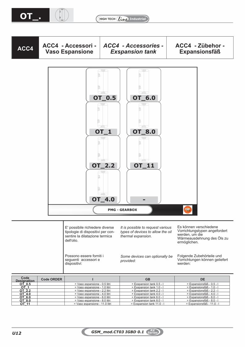
ACC4 ACC4 - Accessori -Vaso Espansione
ACC4 - Accessories -Exspansion tank
ACC4 - Zübehor -Expansionsfäß
OT_.
CodeDesignation Code ORDER I GB DE
OT_0.5 = Vaso espansione - 0.5 litri = Exspansion tank 0.5 - l = Expansionsfäß - 0.5 - lOT_1 = Vaso espansione - 1.0 litri = Exspansion tank 1.0 - l = Expansionsfäß - 1.0 - l
OT_2.2 = Vaso espansione - 2.2 litri = Exspansion tank 2.2 - l = Expansionsfäß - 2.2 - lOT_4.0 = Vaso espansione - 4.0 litri = Exspansion tank 4.0 - l = Expansionsfäß - 4.0 - lOT_6.0 = Vaso espansione - 6.0 litri = Exspansion tank 6.0 - l = Expansionsfäß - 6.0 - lOT_8.0 = Vaso espansione - 8.0 litri = Exspansion tank 8.0 - l = Expansionsfäß - 8.0 - lOT_11 = Vaso espansione - 11.0 litri = Exspansion tank 11.0 - l = Expansionsfäß - 11.0 - l
Possono essere forniti iseguenti accessori edispositivi:
Some devices can optionally beprovided:
Folgende Zubehörteile undVorrichtungen können geliefertwerden:
E' possibile richiedere diversetipologie di dispositivi per con-sentire la dilatazione termicadell'olio.
It is possible to request varioustypes of devices to allow the oilthermal expansion.
Es können verschiedeneVorrichtungstypen angefordertwerden, um dieWärmeausdehnung des Öls zuermöglichen.

U13
Industrial
U
GSM_mod.CT03 IGBD 0.1RX
Series
5 10 15 20 25 30 35 40 45 50 55 60
1.0
2.0
3.0
4.0
5.0
6.0
7.0
8.0
9.0
10.0
11.0
12.0
13.0
14.0
15.0
16.0
17.0
18.0
19.0
20.0
21.0
22.0
23.0
24.0
25.0
26.0
27.0
28.0
29.0
30.0
31.0
32.0
33.0
34.0
35.0
36.0
37.0
38.0
39.0
40.0
41.0
42.0
45.0
50.0
60.0
70.0
80.0
90.0
100.0
110.0
120.0
130.0
140.0
150.0
160.0
170.0
180.0
190.0
05
1
2.2
4.0
6.0
8.0
11
°C
T
5 30 60
L
Differenza temperatura tra temperatura funzionamento riduttoree temperatura ambiente - Temperature difference in between the
operating temperature and the ambient temperature
-Temperaturschwankungen zwischen der Betriebstemperaturund der Raumtemperatur
Scelta Grandezza OTOT selectionOT Auswahl
Litri RiduttoreGearbox litersLiter derGetriebe
OT_.

U14
Industrial
GSM_mod.CT03 IGBD 0.1RX
Series
OT 05
OT 1 OT 2.2
OT 4.0 OT 6.0
NUT
M8x8
OT 8.0 OT 11
80
40
60140
55
120230
G 3/8
G 3/8
G 1/4
G 1/4
130
40
140220
G 3/8
G 1/4
75
175325
G 3/8
G 1/4
80
130
85
160330
G 3/8
G 1/4
160
75
265415
G 3/8
G 1/4
160
75
420570
G 3/8
G 1/4
160
OT_.

U15
Industrial
U
GSM_mod.CT03 IGBD 0.1RX
Series
ACC5ACC5 - Accessori -
sistema conscambiatore
ACC5 - Accessories -Cooling Unit
ACC5 - Zübehor -Kühlanlage
PMG - GEARBOX
RFW1
RFW2
RFW3
RFW4
RFW5
RFW6
RFW7
RFW8
da fare
da fare
da fare
RFA1-
RFA2
RFA3-A
RFA3-B
RFA4
RFA5
RFA6
RFA7
CP PW 1
CP P2W
CP P3W
CP P4W
RFW_.
1.0 - Gruppo di raffreddamento 1.0 - Kühlanlage1.0 - Cooling Unit
CodeDesignation Code ORDER I GB DE
RFW1
= RFW. - sistema con scambiatore acqua-olio = RFW. - water/oil exchanger = RFW. - System mit Wasser-/Ölaustauscher
RFW2RFW3RFW4RFW5RFW6RFW7RFW8CPWP. = Gruppo di raffreddamento acqua-olio
con pompa asservita= Water/oil cooling unit with shaft-driven pump = Wasser-/Ölkühlaggregat mit mit Nebenpumpe
RFA1
= RFA. - sistema con scambiatore aria-olio = RFA. - air/oil exchanger = RFA. - System mit Luft-/Ölaustauscher
RFA2RFA3-ARFA3-BRFA4RFA5RFA6RFA7
Possono essere forniti iseguenti accessori edispositivi:
Some devices can optionally beprovided:
Folgende Zubehörteile undVorrichtungen können geliefertwerden:
E' possibile richiedere diversetipologie di dispositivi per con-sentire il raffreddamento dell'o-lio, utilizzando degli scambiatoridi calori esterni al riduttore.
It is possible to request varioustypes of devices to allow thecooling of the oil, by using heatexchangers outside thegearbox.
Es können verschiedeneVorrichtungstypen angefordertwerden, um die Abkühlung desÖls unter Einsatz von extern amGetriebe angeordnetenWärmetauschern zu ermöglichen.

U16
Industrial
GSM_mod.CT03 IGBD 0.1RX
Series
CPWP.
E' possibile fornire, solamente a richiestae per piccole potenze da scambiare, grup-pi di raffreddamento che si avvalgono dipompe asservite anzichè di motopompe.Dato che gli impianti vengono fissati diret-tamente al riduttore è necessario, in fased'ordine, indicare schematicamente even-tuali ingombri che ne pregiudicano il piaz-zamento.
Cooling systems connected to the mainmotor motion ( instead of having own elec-tric motor like motor pumps ) to cool downlimited temperature ranges are availableon request. Since these systems are di-rectly connected to the gearbox it is nec-essary, together with the order to providedimensions to let GSM SpA verify possibleassembly inconveniences.
Es ist möglich, nur auf Anfrage und für ge-ringe Thermische Leistungen, Kühlungs-systeme mit statt einer Motorpumpe einePumpe die direkt von den Zahnrädern desGetriebe angetrieben werden, zu liefern.Da diese Systeme direkt am Getriebe an-gebaut werden, ist es notwendig gemein-sam mit der Bestellung auch eineEinbauskizze zu bekommen um eventuel-le Probleme zu vermeiden.
1.0 - CPWP. - Gruppo di raffreddamentoaria-olio con pompa asservita
1.0 - CPWP. - Luft-/Ölkühlaggregat mitmit Nebenpumpe
1.0 - CPWP. - Air/oil cooling unit with
shaft-driven pump
CPWP.
1.0 - Gruppo di raffreddamento 1.0 - Kühlanlage1.0 - Cooling Unit

U17
Industrial
U
GSM_mod.CT03 IGBD 0.1RX
Series
Il raffreddamento con scambiatore di calore puòessere suddiviso in due tipologie principali: conscambiatore acqua-olio e con scambiatore ariaolio, ogni categoria è divisa in più grandezze,con potenze di scambio diversificate.Ogni gruppo di raffreddamento è fornitoseparatamente al riduttore; i tubi dicollegamento tra riduttore ed impianto non sonoa carico GSM.
Die Kühlung mittels Wärmeaustauschers lässtsich in zwei Haupttypologien unterteilen: mitWasser-/Ölaustauscher undLuft-/Ölaustauscher. Jede Kategorie ist inmehrere Größen unterteilt, die unterschiedlicheAustauschleistungen aufweisen.Jedes Kühlaggregat wird in vom Getriebegetrennter Form geliefert; dieVerbindungsleitungen zwischen Getriebe undAnlage gehen nicht zu Lasten der GSM.
Water/oil and air/oil heat exchangers are
available in a range of different sizes and heat
exchange capacities.
Each cooling unit is supplied separate from the
gear unit; pipes or hoses for connection to plant
must be provided by GSM.
1.0 - Gruppo di raffreddamento 1.0 - Kühlanlage1.0 - Cooling Unit
1.1 - RFW - sistema conscambiatore acqua-olio
1.1 - RFW - System mitWasser-/Ölaustauscher
1.1 - RFW - water/oil exchangerRFW
1.1.1 GeneralitàSempre più spesso è indispensabile raffreddarel’olio con acqua se si ha sufficiente disponibilitàd’acqua pulita.In alcuni casi, poi, non è possibile collegare loscambiatore olio-acqua direttamente allo scaricoa causa della presenza nel circuito di colpid’ariete, e si è costretti a realizzare un circuitoseparato con una pompa autonoma dicircolazione, tubazioni, pressostato ed impiantoelettrico.Per questi casi, ora sempre più frequenti, GSMS.p.A. ha provveduto inserendo nella propriaproduzione i gruppi autonomi di raffreddamentoserie RFW, che risolvono nel migliore dei modi ilcompito di raffreddare l’olio, indipendentementedall’impianto idraulico primario.L’unità è stata studiata per raffreddare l’olio econsiste in un scambiatore a fascio tubiero che,ponendo a contatto l'olio messo in circolazionedalla motopompa con la serpetina dell'acqua,asporta il calore ceduto.Tutte le parti metalliche sono protette daverniciatura a polvere per garantire una lungadurata agli agenti atmosferici.Nell’esecuzione standard l’unità è fornita contutti i particolari assemblati su un telaio.
1.1.2 Stato fornitura e caratteristiche tecnicheLe unità di raffreddamento serie RFW standardsono composte da:1 - Uno scambiatore di calore acqua-olio;2 - Una motopompa composta da un motore a 4poli in forma B3/B5, alimentazione standardtrifase 230-400V 50 hz e da una pompa adingranaggi o a vite;3 - Manometro 0-16 bar montato fra pompa escambiatore di calore;4 - Termometro analogico 0-120 °C, montato inuscita dallo scambiatore;5 - Pressostato di minima con contatti inscambio, montato fra pompa e scambiatore dicalore;6 - Filtro, in mandata al serbatoio, per la puliziadell’olio scaricato;7 - Indicatore elettrico di intasamento
A – Aspirazione della pompa;M – Mandata della pompa.
1.1.1 Allgemeine InformationenImmer häufiger ist es unerlässlich das Öl mitWasser zu kühlen, wenn ausreichend Wasserverfügbar ist. In einigen Fällen ist ein direkterAnschluss des Öl-Wasser-Wärmeaustauschersan den Anschluss aufgrund von Widderstößenim System nicht möglich und man ist dazugezwungen einen separaten Kreislauf mit einereigenständigen Umlaufpumpe, Leitungen,Druckwächter und elektrischer Anlage zurealisieren.Für diese immer häufigerauftretenden Fälle hat die GSM S.p.A.autonome Kühlaggregate der Serie RFW in ihrProgramm aufgenommen, die die Aufgabe derÖlkühlung, von der hydraulischen Hauptanlageunabhängig, in der besten Art und Weiseerfüllen.Diese Einheit wurde für das Kühlen desÖls entwickelt und stellt sich in einemWärmeaustauscher mit Rohrbündel dar, der dieabgestrahlte Wärme ableitet, indem er das vonder Motorpumpe in den Umlauf gebrachte Ölmit der Wasserrohrschlage in Kontakt bringt.Alle Metallteile sind durch einePulverlack-lackierung geschützt, die einen langanhalteden Schutz gegen Umweltbelastungengewährt.In der Standardversion wird die Einheit bereits mitallen am Rahmen montierten Teilen geliefert.
1.1.2 Lieferzustand und technische Eigen-schaftenDie Kühleinheiten der Serie RFW Standardsetzten sich aus folgenden Komponentenzusammen:1 - einen Wasser-Öl-Wärmeaustauscher;2 - einer Motorpumpe bestehend aus einem4-poligem Motor in Bauform B3/B5,Standard-Drehstromversorgung 230-400V 50Hz und einer Zahnrad- oder Schneckenpumpe;3 - Manometer 0-16 bar, zwischen Pumpe undWärmeaustauscher montiert;4 - analoges Thermometer 0-120 °C, amAusgang des Wärmeaustauschers montiert;5 - Mindestdruckwächter mitWechselkontakten, zwischen PumpeWärmeaustauscher montiert;6 - Filter, im Zulauf zum Behälter, für dieReinigung des abgelassenen Öls7 - elektrische Verstopfungsanzeige.
A – Ansaugung der Pumpe;M – Zulauf der Pumpe.
1.1.1 General featuresIf sufficient clean water is available, it is oftenrequired to cool down oil with water. Moreover, insome cases it is not possible to connect oil-waterexchanger directly to the drainage due to waterhammers in the circuit, and user is thus forced toset up a separated circuit with independentcirculation pump, tubing, pressure switch andelectric system. These cases are very frequentnowadays, this is why GSM S.p.A. has added toits product range the independent cooling unitsof the RFW series, that best carry out the task ofcooling down oil in an independent way withrespect to the main hydraulic system. This unit isdesigned for cooling down oil and consists in atube bundle heat exchanger that sinks heatreleased from oil (circulated by motor pump)thanks to contact with water coil.All metal parts are powder-coated to ensure longlasting protection against weather conditions.In the standard version, the unit features all partsassembled to a frame.
1.1.2 Supply scope and specificationsStandard cooling units of the RFW series consistof:1 - A water-oil heat exchanger;2 - A motor pump made of a 4-pole motor ratedB3/B5, standard three-phase 230-400V 50 Hzpower and a gear or screw pump;3 - 0-16 bar Pressure gauge mounted betweenpump and heat exchanger;4 - 0-120 °C Analogue thermometer mounted atexchanger outlet;5 - Minimum pressure switch with switchcontacts, mounted between pump and heatexchanger;6 - Filter, at tank inlet, for cleaning drained oil;7 - Electrical clogging indicator
A – Pump inlet;M – Pump outlet.
RFW.

U18
Industrial
GSM_mod.CT03 IGBD 0.1RX
Series
1.1.3 Dimensionamento e CaratteristicheFunzionaliPer la scelta del gruppo di raffreddamento sirimanda alla Sezione A-B.
CARATTERISTICHE TECNICHENella Tabella sottostante riportiamo lecaratteristiche tecniche
GrandezzaSize
BaugrößeSize
PesoWeight
Gewicht[[Kg]
VolumeOlio
Oil volumeÖlvolumen
[dm3]
MotopompaMotor PumpMotorpumpe
ScambiatoreExchanger
Wärmeaustauscher
Campo ApplicazioneApplication
Einsatzbereich
[*1] [*2] [*3] [*4]
Connessione OlioOil connectionÖlanschluss [*7] [*8]
Raffreddamento
CoolingKühlung
LubrificazioneForzataForced
lubricationZwangsschmi
erung[*5] [*6]
1 13 0,4 IngranaggiGear-typeZahnräder
0.37 6
230/40050
G 1/2" G 3/4" G 1/2"
8-30
SIYESJA
SIYESJA
2 15 0,6 0.37 6 10-30
3 18 1,2 0.55 16 16-30
4 44 3,0
ViteScrew-typeSchnecke
1.5 30 G 3/4" G 1" 1/4 G 1" 40-110
5 70 4,5 2.2 80 G 1" 1/4 G 1" 1/2 G 1" 80-110
6 On request 7.50 135.0 G 2" On request G 1" 90-110
7 On request 7.50 200.0 G 2" On request G 1" 180-220
8 On request 7.50 200.0 G 2" On request G 1" 270-330
Legenda/Legend/Legende[*1] Tipo Pompa/Pump type/Pumpentyp[*2] Potenza /Power/Leistung [kW][*3] Portata /Flow rate/.Durchsatz [dm3 / min][*4] Alimentazione /Power supply/Versorgung [V / Hz][*5] Aspirazione /Inlet/Ansaugung[*6] Mandata /Outlet/Zulauf[*7] Connessione Acqua /Water connection/Wasseranschluss[*8] Portata Acqua /Water flow rate/Wasserdurchsatz [l / min]
1.1.4 Dimensioni 1.1.4 Maße1.1.4 Dimensions
1.1.3 Sizes and Functional FeaturesPlease refer to Section A-B for indications onhow to choose the suitable cooling unit.
SPECIFICATIONSThe specifications are given in the table below
1.1.3 Bemaßung und FunktionseigenschaftenFür die Wahl des richtigen Kühlaggregatsverweisen wir auf die Sektion A-B.
TECHNISCHE EIGENSCHAFTENIn der nachstehenden Tabelle werden dietechnischen Eigenschaften angegeben.
1.0 - Gruppo di raffreddamento 1.0 - Kühlanlage1.0 - Cooling Unit
RFW 2 RFW 3RFW 1
350230
350
600
43
0
12 12
RFW 5RFW 4
50
0
71552012 12
45
30 30
60
55
Sca
la1
:10
n.4
fori
Ø11
15
3
XX
520
50
0
860860860
710
510
320280
35
0
280450
12 12
35
0
320
280450
28012 12
RFW 7 RFW 8RFW 6
On requestOn request On request
RFW.RFW.

U19
Industrial
U
GSM_mod.CT03 IGBD 0.1RX
Series
1.2.1 GeneralitàSempre più spesso è indispensabile raffreddare l’oliocon l’aria, poiché non si ha sufficiente disponibilitàd’acqua.In alcuni casi poi, non è possibile collegare loscambiatore aria-olio direttamente allo scarico a causadella presenza nel circuito di colpi d’ariete, e si ècostretti a realizzare un circuito separato con unapompa autonoma di circolazione, tubazioni, termostatoed impianto elettrico.La GSM S.p.A. ha provveduto inserendo nella propriaproduzione i gruppi autonomi di raffreddamento serieRFA, che risolvono nel migliore dei modi il compito diraffreddare l’olio, indipendentemente dall’impiantoidraulico primario.Un problema che oggi si fa sempre più pressante è ilrisparmio nei consumi d’energia.Utilizzando per il raffreddamento acqua a perdere sispreca calore che l’olio ha ceduto all’acqua.Utilizzando invece l’aria emessa dai gruppi RFA èpossibile recuperare il calore ceduto dall’olio, scaldandol’ambiente in cui essi sono installati.Oggi, il consumo dell’acqua per usi industriali ha costisempre molto elevati ed in molti casi le aziende devonomunirsi d’impianti refrigeranti in circuito chiusodell’acqua di raffreddamento e nella maggior parte deicasi esse sono macchine frigorifere.Il consumo d’energia di questi impianti è ingente ed èpari a circa il 30% della potenza da disperdere.Con i gruppi autonomi serie RFA questo consumoscende al 6%, con un considerevole risparmio d’energiaelettrica e quindi di costo d’esercizio, senza contare ilcosto iniziale notevolmente inferiore.L’unità è stata studiata per raffreddare l’olio e consistein un radiatore che è attraversato dal flusso d’ariagenerato da un ventilatore, il quale lambendo lealettature in alluminio della massa radiante asporta ilcalore ceduto dall’olio, che circola nel radiatore dalbasso verso l’alto grazie alla pompa a vite di ricircolo.Il controllo del corretto funzionamento della macchina èregolato dai termostati che ne ottimizzano ilfunzionamento nel caso d’eventuali sbalzi ditemperatura.Tutte le parti metalliche sono protette da verniciatura apolvere per garantire una lunga durata agli agentiatmosferici.Nell’esecuzione standard l’unità è fornita con tutti iparticolari assemblati su un telaio palettizzabile
1.2.2 Stato fornitura e caratteristiche tecnicheLe unità di raffreddamento serie RFA standard sonocomposte da:1. Uno scambiatore di calore aria-olio;2. Una motopompa composta da un motore a 4 poliper le grandezze RFA1, RFA2, RFA3 e 2 poli per legrandezze RFA4, RFA5 in forma B3/B5, alimentazionestandard trifase 230-400V 50 hz.Per i gruppi facenti parte dello schema A (RFA1 –RFA2 – RFA3) il motore della motopompa è ilmedesimo del motoventilatore.3. SCHEMA A: Manometro 0-12 bar con funzioneaggiuntiva di indicatore visivo di intasamento;SCHEMA B: Manometro 0-16 bar montato fra pompae scambiatore di calore ;4. Termometro analogico 0-120 °C, montato in uscitadallo scambiatore.5. Pressostato di minima con contatti in scambio,montato fra pompa e scambiatore di calore.6.Filtro, in mandata al serbatoio, per la pulizia dell’olioscaricato.
1.2.1 AllgemeineInformationenImmer häufiger ist es unerlässlich das Ölmit Luft zu kühlen, da man nicht ausreichend Wasserverfügbar hat. In einigen Fällen ist ein direkterAnschluss des Luft-Wasser- Wärmeaustauschers anden Anschluss aufgrund von Widderstößen im Systemnicht möglich und man ist dazu gezwungen einenseparaten Kreislauf mit einer eigenständigen Um-laufpumpe, Leitungen, Thermostat und elektrischerAnlage zu realisieren. Die GSM S.p.A. hat autonomeKühlaggregate der Serie RFA in ihr Programmaufgenommen, die die Aufgabe der Ölkühlung, vonder hydraulischen Hauptanlage unabhängig, in derbesten Art und Weise erfüllen. Die Energieeinsparungist heute ein Problem, dem immer mehr Bedeutungzukommt. Wird für die Kühlung nichtwiederverwendbares Wasser verwendet, geht dieWärme verloren, die das Öl ans Wasser abgegebenhat. Wird dagegen von den RFA-Aggregatenzugeführte Luft verwendet, kann die an der Ölabgegebene Wärme zurückgewonnen und für dieHeizung des Raums verwendet werden, in dem sieinstalliert sind. Der Wasserkonsum für denindustriellen Einsatz ist heute mit immer stärkersteigenden Kosten verbunden und in vielen Fällenmüssen sich die Firmen mit Kühlsystemen imgeschlossenen Kühlwasserkreislauf ausrüsten, dabeihandelt es sich in den meisten Fällen umKühlmaschinen. Der Energieverbrauch dieser Anlagenist beachtlich und entspricht ungefähr 30% derverbrauchbaren Leistung. Mit den autonomenAggregaten der Serie RFA sinkt dieser Konsum auf6% ab, eine erhebliche Einsparung bei Strom also beiBetriebskosten, ohne dabei die erheblich geringerenAnschaffungskosten zu berücksichtigen. Die Einheitwurde für die Kühlung von Öl ent- wickelt und bestehtaus einem Kühler, der von einem durch einenVentilator erzeugten Luftstrom durchquert wird, der dieAluminiumrippen der Kühlmasse “umspült” und dievom Öl abgegebene Wärme abnimmt. Das Öl zirkuliertdank der Schneckenumlaufpumpe im Kühler vonunten nach oben. Die Steuerung des korrektenMaschinenbetriebs wird von den Thermostatengeregelt, die den Betrieb im Fall von eventuellenTemperaturschwankungen optimiert. Alle Metallteilesind durch eine Pulver- lacklackierung geschützt, dieeinen lang anhaltenden Schutz gegenUmweltbelastungen gewährleistet. In derStandardversion wird die Einheit bereits mit allen aneinem palettierbaren Rahmen montierten Teilengeliefert.
1.2.2 Lieferzustand und technische EigenschaftenDie Kühleinheiten der Serie RFA Standard setzen sichwie folgt zusammen:1. Ein Luft-Öl-Wärmeaustauscher;2. Eine Motorpumpe bestehend aus einem 4-poligemMotor für die Baugrößen RFA1, RFA2, RFA3 oder2-poligem Motor für die Baugrößen RFA4, RFA5 inBauform B3/B5, Standard-Drehstromversorgung230-400V 50 Hz. Bei den Aggregaten, die zumSchema A (RFA1 – RFA2 – RFA3) gehören werdenMotorpumpe und Ventilator vom selben Motorbetrieben.3. SCHEMA A: Manometer 0-12 bar, zwischen Pumpeund Wärmeaustauscher montiert;mit Zusatzanzeigefür blockierten ÖlflussSCHEMA B: Manometer 0-16 bar, zwischen Pumpeund Wärmeaustauscher montiert;4. Analoges Thermometer 0-120 °C, amAusgang des Wärmeaustauschers montiert;5. Mindestdruckwächter mit Umschaltkontakten,zwischen Pumpe und Wärmeaustauscher montiert;6. Filter, im Zulauf zum Behälter, für die Reinigung desabgelassenen Öls;
1.2.1 General featuresWhen no sufficient water is available, it is more and
more often indispensable to cool down oil with air.
Moreover, in some cases it is not possible to connect
air-oil exchanger directly to the drainage due to water
hammers in the circuit, and user is thus forced to set
up a separated circuit with independent circulation
pump, tubing, thermostat and electric system.
To meet the needs of these instances, GSM S.p.A.
has added to its product range the independent
cooling units of the RFA series, that best carry out the
task of cooling down oil in an independent way with
respect to the main hydraulic system.
Nowadays, energy-saving is a major issue and using
water for cooling without recycling it means wasting
the heat released by oil to water. While, using air
issued by the RFA units, it is possible to recover the
heat released by oil and use it to heat the room where
they are installed. Water for industrial use is quite
expensive and in many cases businesses need to set
up closed-loop water cooling systems and most of the
time they are refrigerating machines. Power
consumption of these systems is huge, equal to about
30% of power to be wasted. With RFA series
independent units this consumption is reduced to 6%,
with a considerable saving in power and thus in
running costs and with a remarkably lower starting
cost. The unit is designed to cool down oil and
consists in a radiator that is in the air flow generated
by a fan; while oil is circulated in the radiator from
bottom up by the recirculation screw pump, oil heat is
dissipated by the air flow lapping on the aluminium fins
of the radiator core. Machine correct operation is
controlled by thermostats optimising its operation in
case of any sudden change of temperature.
All metal parts are powder-coated to ensure long
lasting protection against weather conditions.
In the standard version, the unit features all parts
assembled to a frame which can be placed on a pallet.
1.2.2 Supply scope and specifications
Standard cooling units of the RFA series consist of:
1. An air-oil heat exchanger;
2. A motor pump made of a 4-pole motor for sizes RFA1,RFA2, RFA3 and 2-pole motor for sizes RFA4, RFA5rated B3/B5, standard three-phase 230-400V 50 Hzpower. For units belonging to diagram A (RFA1 – RFA2– RFA3) motor pump motor is the same as motor fanone.3. DIAGRAM A: 0-12 bar Pressure gauge mounted
between pump and heat exchanger; withadded function of oil flow blocking displayDIAGRAM B: 0-16 bar Pressure gauge mounted
between pump and heat exchanger;
4. 0-120 °C Analogue thermometer mounted at
exchanger outlet.
5. Minimum pressure switch with switch contacts,
mounted between pump and heat exchanger.
6. Filter, at tank inlet, for cleaning drained oil.
1.0 - Gruppo di raffreddamento 1.0 - Kühlanlage1.0 - Cooling Unit
1.2 - RFA - sistema conscambiatore aria-olio
1.1 - RFA - System mit Luft-/Ölaustauscher
1.2 - RFA - air/oil exchangerRFA
RFA.

U20
Industrial
GSM_mod.CT03 IGBD 0.1RX
Series
7. Indicatore elettrico di intasamento del filtroolio.8. Scatola Morsettiera;9.Termostato di regolazione:
A – Aspirazione della pompa;M – Mandata della pompa.
NOTE SPECIFICHE - SCHEMA A :Il gruppo RFA3 è fonito con sonda ditemperatura e termostato.
ATTENZIONE:Il gruppo RFA3 è fornito secondo lo schema Aquando l’applicazione necessita di soloraffreddamento altrimenti è fornito RFA3secondo lo schema B.
7. Elektrische Verstopfungsanzeige desÖlfilters8. Klemmenkasten;9. Regelthermostat:
A – Ansaugung der Pumpe;M – Zulauf der Pumpe.
SPEZIFISCHE HINWEISE - SCHEMA A :Das Aggregat RFA3 wird mit einerTemperatursonde und einem Thermostat geliefert.
ACHTUNG:Das Aggregat RFA3 wird dem Schema Agemäß geliefert, wenn die Applikation nur einerKühlung bedarf, andernfalls wird das RFA3dem Schema B entsprechend geliefert.
7. Electrical clogging indicator of oil filter.
8. Terminal board box;9. Adjustment thermostat:
A – Pump inlet;M – Pump outlet.
SPECIFIC NOTES - DIAGRAM A:RFA3 unit is supplied together with temperatureprobe and thermostat.
NOTICE:RFA3 unit is supplied as per diagram A when theapplication only needs cooling, while in othercases RFA3 is supplied as per diagram B.
SCHEMA ADIAGRAM ASCHEMA A
SCHEMA B
BD BIAGRAMSCHEMA
SchemaDiagramSchema
GrandezzaSize
BaugrößeSize
PesoWeight
Gewicht[[Kg]
VolumeOlio
Oil volumeÖlvolumen
[dm3]
MotopompaMotor PumpMotorpumpe
ScambiatoreExchanger
Wärmeaustauscher
Campo ApplicazioneApplication
Einsatzbereich
[*1] [*2] [*3] [*4]
Connessione OlioOil connectionÖlanschluss
[*7] [*8] [*9]
RaffreddamentoCoolingKühlung
Lubrifica-zione For-
zataForced
lubricationZwangs-schmier.
[*5] [*6]
A 1 20 3.0
IngranaggiGear-typeZahnräder
0.55 6
400 / 50TrifaseThree-phase
dreiphasig
G 1/2"
G 1/2"
0.55 600 64
SIYES
JA
SIYES
JAA 2 27 3,6 0.55 13 0.75 850 68
A 3-A 61 5,5 1.1 34 G 3/4" 1.1 2000 75NONO
NEIN
B 3-B 75 5,5Vite
Screw-type
Schnecke
1.5 30 G 1" G 1" 1/4 0.23 2700 72
SIYES
JA
B 4 96 15 3.0 112
G 1" 1/4 G 1" 1/2
0.23 3500 72
B 5 118 15 3.0 1120.56
6300 75
B 6 127 16 3.0 160 7450 79
B 7 140 20 3.0 160 0.9 9500 79
Legenda/Legend/Legende.[*1] Tipo Pompa/Pump type/Pumpentyp.[*2] Potenza /Power/Leistung [kW][*3] Portata /Flow rate/Durchsatz [dm3 / min][*4] Alimentazione /Power supply/Versorgung [V / Hz][*5] Aspirazione /Inlet/Ansaugung[*6] Mandata /Outlet/Zulauf .[*7] Potenza /Power/Leistung [kW][*8] Portata Aria /Air flow rate/Luftdurchsatz.[m3 / h][*9] Rumorosità /Noise/Geräuschpegel.[dB]
1.0 - Gruppo di raffreddamento 1.0 - Kühlanlage1.0 - Cooling Unit
1.2.3 Dimensionamento e CaratteristicheFunzionaliPer la scelta del gruppo di raffreddamento sirimanda alla Sezione A-B.
CARATTERISTICHE TECNICHENella Tabella sottostante riportiamo lecaratteristiche tecniche
1.2.3 Sizes and Functional FeaturesPlease refer to Section A-B for indications onhow to choose the suitable cooling unit.
SPECIFICATIONSThe specifications are given in the table below
1.2.3 Bemaßung und FunktionseigenschaftenFür die Wahl des richtigen Kühlaggregatsverweisen wir auf die Sektion A-B.
TECHNISCHE EIGENSCHAFTENIn der nachstehenden Tabelle werden dietechnischen Eigenschaften angegeben.
RFA.

U21
Industrial
U
GSM_mod.CT03 IGBD 0.1RX
Series
1.2.4 DimensioniNelle tabelle sottostanti sono riportati gliingombri dei gruppi:- SCHEMA A: RFA 1, RFA 2, RFA3;- SCHEMA B: RFA 3, RFA 4, RFA5, RFA6,RFA7;
1.2.4 MaßeIn den nachstehenden Tabelle werden dieMaße der Aggregate angegeben:- SCHEMA A: RFA 1, RFA 2, RFA3;- SCHEMA B: RFA 3, RFA 4, RFA5, RFA6,RFA7;
1.2.4 DimensionsThe tables below show units overall dimensions:
- DIAGRAM A: RFA 1, RFA 2, RFA3;- DIAGRAM B: RFA 3, RFA 4, RFA5, RFA6,RFA7;
1.0 - Gruppo di raffreddamento 1.0 - Kühlanlage1.0 - Cooling Unit
RFA 2 RFA 3-ARFA 1
RFA 3-B
SCHEMA A DIAGRAM A SCHEMA A
SCHEMA B DIAGRAM B SCHEMA B
RFA 4
RFA 2RFA 2
RFA 5
51
0
44
0
53
60
50
40
645
710
710
510
91
01
00
13 Ø11
3
3
RFA.

U22
Industrial
GSM_mod.CT03 IGBD 0.1RX
Series
RFA 6 RFA 7
1.0 - Gruppo di raffreddamento 1.0 - Kühlanlage1.0 - Cooling Unit
SCHEMA B DIAGRAM B SCHEMA B
RFA.

U23
Industrial
U
GSM_mod.CT03 IGBD 0.1RX
Series
ACC6ACC6 - Accessori -
LubrificazioneForzata - BEARING
ACC6 - Accessories -Forced lubrification -
BEARING
ACC6 - Zübehor -Zwangsschiemierung -
BEARING
2.0 - Lubrificazione forzata 2.0 - Zwangsschmierung2.0 - Forced lubrication
LFM.LFP.
CodeDesignation Code ORDER I GB DE
LFP1 = Pompa asservita - 0.5 l/min = Shaft-driven pump - 0.5 l/min = Nebenpumpe- 0.5 l/minLFP2 = Pompa asservita - 5 l/min = Shaft-driven pump - 5 l/min = Nebenpumpe- 1.75 l/minLFP3 = Pompa asservita - 1.75 l/min = Shaft-driven pump - 1.75 l/min = Nebenpumpe- 5 l/minLFM1 = Motopompa - 0.5 l/min = Motor pump - 0.5 l/min = Motorpumpe - 0.5 l/minLFM2 = Motopompa - 5 l/min = Motor pump - 5 l/min = Motorpumpe - 5 l/minLFM3 = Motopompa - 10 l/min = Motor pump - 10 l/min = Motorpumpe - 10 l/minLFM4 = Motopompa - 20 l/min = Motor pump - 20 l/min = Motorpumpe - 20 l/minLFM5 = Motopompa - 30 l/min = Motor pump - 30 l/min = Motorpumpe - 30 l/min
Possono essere forniti iseguenti accessori edispositivi:
Some devices can optionally beprovided:
Folgende Zubehörteile undVorrichtungen können geliefertwerden:
E' possibile richiedere diversetipologie di dispositivi per con-sentire la lubrificazione forzatadei cuscinetti.
It is possible to request varioustypes of devices to allow theforced lubrication of thebearings.
Es können verschiedeneVorrichtungstypen angefordertwerden, um dieZwangsschmierung der Lagerzu ermöglichen.

U24
Industrial
GSM_mod.CT03 IGBD 0.1RX
Series
2.0 - Lubrificazione forzata 2.0 - Zwangsschmierung2.0 - Forced lubrication
n1
[min-1
]
Grandezza / Size / Baugröße
802-810 812 814 816 818 820 822 824 826 828 830 832
RXP31751 - n1max G (grease) LFM2
LFM2LFM3 LFM41000 - 1750 G (grease)
0 - 999 G (grease) LFM2
RXP21751 - n1max
G (grease) LFM2LFM2 LFM31000 - 1750
0 - 999 G (grease)
RXP11751 - n1max G (grease) LFM2
1000 - 1750 G (grease) LFM2
0 - 999 G (grease) LFM2
Pos. Mont. M5 - M6Pos. Mont. M5 - M6 Mntg. Pos. M5 - M6 Einbaulage M5 - M6
I valori di n1 max sono riportati nel paragrafo(vedi sezione A verifiche, punto 4).
n1 max values are listed at paragraph(see Section A verification, point 4).
Die Werte von n1 max werden im Paragraph(siehe Abschnitt A „"kontrollen“, Punkt 4,angegeben).
n1
[min-1
]
Grandezza / Size / Baugröße
802-810 812 814 816 818 820 822 824 826 828 830 832
RXO3RXV3 0 - n1max G (grease) LFM3 LFM4
RXO2RXV2
1751 - n1max G (grease) LFM2LFM2
LFM3 LFM41000 - 1750 G (grease)
0 - 999 G (grease) LFM2
RXO1RXV1
1751 - n1maxG (grease) LFM2
LFM2 LFM31000 - 1750
0 - 999 G (grease)
n1
[min-1
]
Grandezza / Size / Baugröße802-808 810 812 814 816 818 820 822 824 826 828 830 832
RXO1RXV1
1751 - n1max G (grease) LFM1 LFM2
1000 - 1750 G (grease) G (grease) LFM1LFM2
0 - 999 G (grease) G (grease)
RXO2RXV2
1751 - n1max G (grease) G (grease) LFM1
LFM21000 - 1750 G (grease) G (grease) LFM1
0 - 999 G (grease) G (grease) LFM1 LFM3RXO3RXV3 0 - n1max G (grease) G (grease) LFM2 LFM3
Pos. Mont. / Mntg. Pos. / Einbaulage M1- M5 - M6
Pos. Mont. / Mntg. Pos. / Einbaulage M3 - M4
M5 M6RXO
M5 M6RXV M1
RXP
RXO - RXV
LFM. LFP.
Lubrificazione cuscinetti superiori
La lubrificazione forzata dei cuscinettisuperiori viene associata alla lubrificazioneforzata degli ingranaggi nel casoquest'ultima sia necessaria.
Schmierung der obenliegenden Lager
Die Zwangsschmierung derobenliegenden Lager wird mit derZwangschmierung der Zahnräder, für dieerforderlich sind, assoziiert.
Upper bearing lubrication
Forced lubrication for upper bearings isnormally associated with forced lubricationfor the gears, where necessary.
2.1 - Applicabilità - LFM. 2.1 - Applikation - LFM.2.1 - Application - LFM.
Attenzione LFP1 e LFP2:1 - La pompa LFP1 & LFP2 è unidirezionale.L’accessorio può essere montato sul riduttoresolo nel caso esso funzioni con unico senso dirotazione, il quale deve essere specificato infase di ordine.2 - Per applicabilità LFP...:consultare servizio tecnico.
Attention LFP1 e LFP2:1 - The LFP1 & LFP2 pump is a one-way pump.The accessory can be installed on the gearboxonly if it works in a single direction of rotation,which must be specified in the order.2 - For LFP... applicability:
contact the technical service.
Achtung LFP1 & LFP2:1 - Die LFP1 & LFP2 ist eine einseitiggerichtete Pumpe.Das Zubehör kann nur am Getriebe montiertwerden, wenn es mit einer einzigenDrehrichtung arbeitet, die bei der Bestellungangegeben werden muss.2 - Für die LFP...Anwendungsmöglichkeit:sich an den technischen Kundendienst wenden.

U25
Industrial
U
GSM_mod.CT03 IGBD 0.1RX
Series
2.0 - Lubrificazione forzata 2.0 - Zwangsschmierung2.0 - Forced lubrication
LFP3
LFP2
Pompa con portata di 1.75 I/min a 750 rpmQuesta pompa è particolarmente indicata per un funzionamento a basso numero di giri,viene ad esempio utilizzata nel primo stadio di riduzione cilindrico di un riduttoreortogonale
Pompa con portata di 5 I/min a 1500 rpm
Pumpe mit Durchsatz von 1,75 I/min bei 750 U/minDiese Pumpe ist besonders für einen Betrieb bei niedriger Drehzahl geeignet. Sie wirdz.B. in der ersten zylindrischen Übersetzungsstufe eines Kegelstirnradgetriebesverwendet.
Pump with 1.75 I/min capacity at 750 rpmThis pump is especially suited for low speed operation. A typical application is the firstreduction spur gear set of a helical bevel gear unit.
Pump with 5 I/min capacity at 1500 rpm
Pumpe mit Durchsatz von 5 I/min bei 1500 U/min
2.2 - Pompa asservita
Queto sistema si realizza accoppiando lapompa direttamente ad un albero del ridut-tore, dal quale prende il moto, e si suddivi-de in 3 tipologie.
LFP1
2.2 - Nebenpumpe
Dieses System wird durch die direktePassung der Pumpe auf eine derGetriebewellen, von der sie dann auchangetrieben wird, gestellt. Hierunterscheidet man 3 Typen.
2.2 - Shaft-driven pump
The pump is coupled directly to and drivenby a gear unit shaft. There are threedifferent types of pumps available.
Pompa con portata di 0.5 I/min a 1500 rpm
Pump with 0.5 I/min capacity at 1500 rpm
Pumpe mit Durchsatz von 0,5 I/min bei 1500 U/min
LFM.LFP.
2.3 - Motopompa
Questo sistema si realizza accoppiandoun motore elettrico ad una pompaidraulica; si suddivide in 5 tipologie ed èfornibile anche separatamente al riduttore.Nelle tabelle sottostanti sono indicate leprincipali caratteristiche tecniche e ledimensioni di questi impianti.
N.B.: la GSM si riserva di scegliere la tipologia piùadatta di Pompa asservita e Motopompa per il buonfunzionamento del riduttore.
I/min Motor P(kW) A AB AD BB C H LB LP P SB IN OUT VTCELFM1 0.5
71A4 0.25 172135 108 109 90 71 220 130 160 15 1/4"GAS 1/4"GAS M8
LFM2 5 135 108 109 90 71 220 147 160 15 3/8"GAS 3/8"GAS M8LFM3 10 80A4 0.55
197155 120 125 100 80 238 200 200 25 1/2"GAS 1/2"GAS M10
LFM4 20 80B4 0.75 155 120 125 100 80 238 210 200 25 3/4"GAS 1/2"GAS M10LFM5 30 90S4 1.1 214 170 131 154 106 90 255 225 200 25 3/4"GAS 1/2"GAS M12
OUT IN
TCE
C
LP LB P
AB=
AD
HS
B
=
2.3 - Motorpumpe
Dieses System wird durch die Passung einesElektromotors an eine Hydraulikpumperealisiert; es lässt sich in 5 Typologienunterteilen und kann auch getrennt vomGetriebe geliefert werden. In dennachstehenden Tabellen werden diewesentlichen technischen Eigenschaften unddie Maße dieser Anlagen angegeben.
2.3 - Motor pump
This is a hydraulic pump coupled with anelectric motor. Available in five differenttypes, motor pumps are also offered as aseparate product. Listed in the tablesbelow are the most significantspecifications and dimensions.
HINWEIS: Die STM behält sich das Recht vor, den fürden guten Getriebebetrieb angemessenen Typ derNeben- oder Motorpumpe wählen zu können.
NOTE: STM reserves the right to select the type ofshaft-driven or motor pump deemed most appropriatefor proper gear unit operation at its discretion.
LFM

U26
Industrial
GSM_mod.CT03 IGBD 0.1RX
Series
ACC6AACC6A - Accessori -
LubrificazioneForzata - GEAR
ACC6A - Accessories -Forced lubrification -
GEAR
ACC6A - Zübehor -Zwangsschiemierung -
GEAR
2.0 - Lubrificazione forzata 2.0 - Zwangsschmierung2.0 - Forced lubrication
Dove necessario è possibile fornireriduttori predisposti o completi dilubrificazione forzata. La lubrificazioneforzata può essere effettuata con Pompaasservita o con Motopompa.
Wo erforderlich können die Getriebe füreine Zwangsschmierung ausgelegt oderbereits damit ausgestattet geliefertwerden. Die Zwangsschmierung kanndurch eine Neben- oder Motorpumpegestellt werden.
Where necessary, gear units are suppliedwith provisions for or incorporated forcedlubrication. Both shaft-driven andmotor-driven pumps are available.
LF.
Maggiori informazioni sugli accessoridisponibili e sulla loro appllicabilità sonodisponibili a richesta.
Weitere Informationen zu denverfügbaren Zubehörteilen und derenAnwendungsmöglichkeiten erhalten Sieauf entsprechende Anfrage.
More information on the accessoriesavailable and on their applicability isavailable upon request.

U27
Industrial
U
GSM_mod.CT03 IGBD 0.1RX
Series
3.0 - Accessori idraulici 3.0 - Hydraulikzubehör3.0 - Hydraulic accessories
ACC7-R
ACC7-R
Hydraulic accessories ACC7A Accessori idraulici -Vibration Sensor
Hydraulic accessories -Vibration Sensor
Hydraulikzubehör - VibrationSensor U18
ACC7B Accessori idraulici -Vibration SWITCH
Hydraulic accessories -Vibration SWITCH
Hydraulikzubehör - VibrationSWITCH U19
ACC7C Accessori idraulici -FILLING
Hydraulic accessories -FILLING
Hydraulikzubehör - FILLING U20
ACC7D Accessori idraulici -PARTICLE MAGNETIC
Hydraulic accessories -PARTICLE MAGNETIC
Hydraulikzubehör -PARTICLE MAGNETIC U21
ACC7E Accessori idraulici -DRAIN
Hydraulic accessories -DRAIN
Hydraulikzubehör - DRAIN U22
ACC7F Accessori idraulici -BREATHER
Hydraulic accessories -BREATHER
Hydraulikzubehör -BREATHER U23
ACC7G Accessori idraulici -LEVEL
Hydraulic accessories -LEVEL
Hydraulikzubehör - LEVEL U24
ACC7H Accessori idraulici -HEATER
Hydraulic accessories -HEATER
Hydraulikzubehör - HEATER U25
ACC7I1Accessori idraulici -TEMPERATURESENSOR
Hydraulic accessories -TEMPERATURE SENSOR
Hydraulikzubehör -TEMPERATURE SENSOR U26
ACC7I2Accessori idraulici -TEMPERATURESWITCH
Hydraulic accessories -TEMPERATURE SWITCH
Hydraulikzubehör -TEMPERATURE SWITCH U29
ACC7I3Accessori idraulici -TEMPERATURETERMOWELL
Hydraulic accessories -TEMPERATURETERMOWELL
Hydraulikzubehör -TEMPERATURETERMOWELL
U30
ACC7L Accessori idraulici -FILTER
Hydraulic accessories -FILTER
Hydraulikzubehör - FILTER U31
ACC7M1 Accessori idraulici -PRESSURE SENSOR
Hydraulic accessories -PRESSURE SENSOR
Hydraulikzubehör -PRESSURE SENSOR U32
ACC7M2 Accessori idraulici -PRESSURE SWITCH
Hydraulic accessories -PRESSURE SWITCH
Hydraulikzubehör -PRESSURE SWITCH U33
ACC7M3Accessori idraulici -PRESSURE Differentialgauge
Hydraulic accessories -PRESSURE Differentialgauge
Hydraulikzubehör -PRESSURE Differentialgauge
U34
ACC7N1 Accessori idraulici -FLOW SENSOR
Hydraulic accessories - FLOWSENSOR
Hydraulikzubehör - FLOWSENSOR U35
ACC7N2 Accessori idraulici -FLOW SWITCH
Hydraulic accessories - FLOWSWITCH
Hydraulikzubehör - FLOWSWITCH U36
ACC7N3 Accessori idraulici -FLOW VISUAL
Hydraulic accessories - FLOWVISUAL
Hydraulikzubehör - FLOWVISUAL U37
ACC7O Accessori idraulici -COOL
Hydraulic accessories - COOL Hydraulikzubehör - COOL U39
ACC7P Accessori idraulici -LEVEL-BREATHER
Hydraulic accessories -LEVEL-BREATHER
Hydraulikzubehör -LEVEL-BREATHER U40
ACC7Z Accessori idraulici -GENERIC
Hydraulic accessories -GENERIC
Hydraulikzubehör -GENERIC U41

U28
Industrial
GSM_mod.CT03 IGBD 0.1RX
Series
3.0 - Accessori idraulici 3.0 - Hydraulikzubehör3.0 - Hydraulic accessories
ACC7A Accessori idraulici -Vibration Sensor
Hydraulic accessories -Vibration Sensor
Hydraulikzubehör -Vibration Sensor
A_HZ.
Maggiori informazioni sugli accessoridisponibili e sulla loro appllicabilità sonodisponibili a richesta.
Weitere Informationen zu denverfügbaren Zubehörteilen und derenAnwendungsmöglichkeiten erhalten Sieauf entsprechende Anfrage.
More information on the accessoriesavailable and on their applicability isavailable upon request.

U29
Industrial
U
GSM_mod.CT03 IGBD 0.1RX
Series
3.0 - Accessori idraulici 3.0 - Hydraulikzubehör3.0 - Hydraulic accessories
B_VS.
ACC7B Accessori idraulici -Vibration SWITCH
Hydraulic accessories -Vibration SWITCH
Hydraulikzubehör -Vibration SWITCH
Maggiori informazioni sugli accessoridisponibili e sulla loro appllicabilità sonodisponibili a richesta.
Weitere Informationen zu denverfügbaren Zubehörteilen und derenAnwendungsmöglichkeiten erhalten Sieauf entsprechende Anfrage.
More information on the accessoriesavailable and on their applicability isavailable upon request.

U30
Industrial
GSM_mod.CT03 IGBD 0.1RX
Series
3.0 - Accessori idraulici 3.0 - Hydraulikzubehör3.0 - Hydraulic accessories
ACC7C Accessori idraulici -FILLING
Hydraulic accessories -FILLING
Hydraulikzubehör -FILLING
C_F.
Maggiori informazioni sugli accessoridisponibili e sulla loro appllicabilità sonodisponibili a richesta.
Weitere Informationen zu denverfügbaren Zubehörteilen und derenAnwendungsmöglichkeiten erhalten Sieauf entsprechende Anfrage.
More information on the accessoriesavailable and on their applicability isavailable upon request.

U31
Industrial
U
GSM_mod.CT03 IGBD 0.1RX
Series
3.0 - Accessori idraulici 3.0 - Hydraulikzubehör3.0 - Hydraulic accessories
ACC7DAccessori idraulici -
PARTICLEMAGNETIC
Hydraulic accessories -PARTICLE MAGNETIC
Hydraulikzubehör -PARTICLE MAGNETIC
D_M.
Maggiori informazioni sugli accessoridisponibili e sulla loro appllicabilità sonodisponibili a richesta.
Weitere Informationen zu denverfügbaren Zubehörteilen und derenAnwendungsmöglichkeiten erhalten Sieauf entsprechende Anfrage.
More information on the accessoriesavailable and on their applicability isavailable upon request.

U32
Industrial
GSM_mod.CT03 IGBD 0.1RX
Series
3.0 - Accessori idraulici 3.0 - Hydraulikzubehör3.0 - Hydraulic accessories
ACC7E Accessori idraulici -DRAIN
Hydraulic accessories -DRAIN
Hydraulikzubehör -DRAIN
E_D.
Maggiori informazioni sugli accessoridisponibili e sulla loro appllicabilità sonodisponibili a richesta.
Weitere Informationen zu denverfügbaren Zubehörteilen und derenAnwendungsmöglichkeiten erhalten Sieauf entsprechende Anfrage.
More information on the accessoriesavailable and on their applicability isavailable upon request.

U33
Industrial
U
GSM_mod.CT03 IGBD 0.1RX
Series
3.0 - Accessori idraulici 3.0 - Hydraulikzubehör3.0 - Hydraulic accessories
ACC7F Accessori idraulici -BREATHER
Hydraulic accessories -BREATHER
Hydraulikzubehör -BREATHER
F_T
Maggiori informazioni sugli accessoridisponibili e sulla loro appllicabilità sonodisponibili a richesta.
Weitere Informationen zu denverfügbaren Zubehörteilen und derenAnwendungsmöglichkeiten erhalten Sieauf entsprechende Anfrage.
More information on the accessoriesavailable and on their applicability isavailable upon request.

U34
Industrial
GSM_mod.CT03 IGBD 0.1RX
Series
3.0 - Accessori idraulici 3.0 - Hydraulikzubehör3.0 - Hydraulic accessories
ACC7G Accessori idraulici -LEVEL
Hydraulic accessories -LEVEL
Hydraulikzubehör -LEVEL
G_L.
Maggiori informazioni sugli accessoridisponibili e sulla loro appllicabilità sonodisponibili a richesta.
Weitere Informationen zu denverfügbaren Zubehörteilen und derenAnwendungsmöglichkeiten erhalten Sieauf entsprechende Anfrage.
More information on the accessoriesavailable and on their applicability isavailable upon request.

U35
Industrial
U
GSM_mod.CT03 IGBD 0.1RX
Series
3.0 - Accessori idraulici 3.0 - Hydraulikzubehör3.0 - Hydraulic accessories
ACC7H Accessori idraulici -HEATER
Hydraulic accessories -HEATER
Hydraulikzubehör -HEATER
H_W.
Maggiori informazioni sugli accessoridisponibili e sulla loro appllicabilità sonodisponibili a richesta.
Weitere Informationen zu denverfügbaren Zubehörteilen und derenAnwendungsmöglichkeiten erhalten Sieauf entsprechende Anfrage.
More information on the accessoriesavailable and on their applicability isavailable upon request.

U36
Industrial
GSM_mod.CT03 IGBD 0.1RX
Series
3.0 - Accessori idraulici 3.0 - Hydraulikzubehör3.0 - Hydraulic accessories
ACC7I1Accessori idraulici -
TEMPERATURESENSOR
Hydraulic accessories -TEMPERATURE
SENSOR
Hydraulikzubehör -TEMPERATURE
SENSOR
I_TPT.
Maggiori informazioni sugli accessoridisponibili e sulla loro appllicabilità sonodisponibili a richesta.
Weitere Informationen zu denverfügbaren Zubehörteilen und derenAnwendungsmöglichkeiten erhalten Sieauf entsprechende Anfrage.
More information on the accessoriesavailable and on their applicability isavailable upon request.

U37
Industrial
U
GSM_mod.CT03 IGBD 0.1RX
Series
3.0 - Accessori idraulici 3.0 - Hydraulikzubehör3.0 - Hydraulic accessories
ACC7I2Accessori idraulici -
TEMPERATURESWITCH
Hydraulic accessories -TEMPERATURE
SWITCH
Hydraulikzubehör -TEMPERATURE
SWITCH
I_TSW.
Maggiori informazioni sugli accessoridisponibili e sulla loro appllicabilità sonodisponibili a richesta.
Weitere Informationen zu denverfügbaren Zubehörteilen und derenAnwendungsmöglichkeiten erhalten Sieauf entsprechende Anfrage.
More information on the accessoriesavailable and on their applicability isavailable upon request.
U38
Industrial
GSM_mod.CT03 IGBD 0.1RX
Series
3.0 - Accessori idraulici 3.0 - Hydraulikzubehör3.0 - Hydraulic accessories
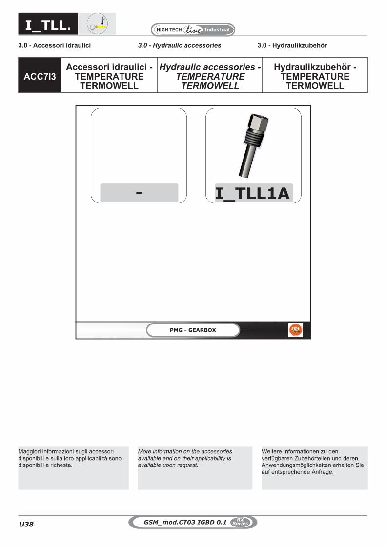
ACC7I3Accessori idraulici -
TEMPERATURETERMOWELL
Hydraulic accessories -TEMPERATURE
TERMOWELL
Hydraulikzubehör -TEMPERATURE
TERMOWELL
I_TLL.
Maggiori informazioni sugli accessoridisponibili e sulla loro appllicabilità sonodisponibili a richesta.
Weitere Informationen zu denverfügbaren Zubehörteilen und derenAnwendungsmöglichkeiten erhalten Sieauf entsprechende Anfrage.
More information on the accessoriesavailable and on their applicability isavailable upon request.

U39
Industrial
U
GSM_mod.CT03 IGBD 0.1RX
Series
3.0 - Accessori idraulici 3.0 - Hydraulikzubehör3.0 - Hydraulic accessories
ACC7L Accessori idraulici -FILTER
Hydraulic accessories -FILTER
Hydraulikzubehör -FILTER
L_FR.
Maggiori informazioni sugli accessoridisponibili e sulla loro appllicabilità sonodisponibili a richesta.
Weitere Informationen zu denverfügbaren Zubehörteilen und derenAnwendungsmöglichkeiten erhalten Sieauf entsprechende Anfrage.
More information on the accessoriesavailable and on their applicability isavailable upon request.

U40
Industrial
GSM_mod.CT03 IGBD 0.1RX
Series
3.0 - Accessori idraulici 3.0 - Hydraulikzubehör3.0 - Hydraulic accessories
ACC7M1 Accessori idraulici -PRESSURE SENSOR
Hydraulic accessories -PRESSURE SENSOR
Hydraulikzubehör -PRESSURE SENSOR
M_PSR.
Maggiori informazioni sugli accessoridisponibili e sulla loro appllicabilità sonodisponibili a richesta.
Weitere Informationen zu denverfügbaren Zubehörteilen und derenAnwendungsmöglichkeiten erhalten Sieauf entsprechende Anfrage.
More information on the accessoriesavailable and on their applicability isavailable upon request.

U41
Industrial
U
GSM_mod.CT03 IGBD 0.1RX
Series
3.0 - Accessori idraulici 3.0 - Hydraulikzubehör3.0 - Hydraulic accessories
ACC7M2 Accessori idraulici -PRESSURE SWITCH
Hydraulic accessories -PRESSURE SWITCH
Hydraulikzubehör -PRESSURE SWITCH
M_PSW.
Maggiori informazioni sugli accessoridisponibili e sulla loro appllicabilità sonodisponibili a richesta.
Weitere Informationen zu denverfügbaren Zubehörteilen und derenAnwendungsmöglichkeiten erhalten Sieauf entsprechende Anfrage.
More information on the accessoriesavailable and on their applicability isavailable upon request.

U42
Industrial
GSM_mod.CT03 IGBD 0.1RX
Series
3.0 - Accessori idraulici 3.0 - Hydraulikzubehör3.0 - Hydraulic accessories
ACC7M3Accessori idraulici -
PRESSUREDifferential gauge
Hydraulic accessories -PRESSURE Differential
gauge
Hydraulikzubehör -PRESSURE Differential
gauge
M_PDG.
Maggiori informazioni sugli accessoridisponibili e sulla loro appllicabilità sonodisponibili a richesta.
Weitere Informationen zu denverfügbaren Zubehörteilen und derenAnwendungsmöglichkeiten erhalten Sieauf entsprechende Anfrage.
More information on the accessoriesavailable and on their applicability isavailable upon request.

U43
Industrial
U
GSM_mod.CT03 IGBD 0.1RX
Series
3.0 - Accessori idraulici 3.0 - Hydraulikzubehör3.0 - Hydraulic accessories
ACC7N1 Accessori idraulici -FLOW SENSOR
Hydraulic accessories -FLOW SENSOR
Hydraulikzubehör -FLOW SENSOR
N_FSR.
Maggiori informazioni sugli accessoridisponibili e sulla loro appllicabilità sonodisponibili a richesta.
Weitere Informationen zu denverfügbaren Zubehörteilen und derenAnwendungsmöglichkeiten erhalten Sieauf entsprechende Anfrage.
More information on the accessoriesavailable and on their applicability isavailable upon request.

U44
Industrial
GSM_mod.CT03 IGBD 0.1RX
Series
3.0 - Accessori idraulici 3.0 - Hydraulikzubehör3.0 - Hydraulic accessories
ACC7N2 Accessori idraulici -FLOW SWITCH
Hydraulic accessories -FLOW SWITCH
Hydraulikzubehör -FLOW SWITCH
N_FSW.
Maggiori informazioni sugli accessoridisponibili e sulla loro appllicabilità sonodisponibili a richesta.
Weitere Informationen zu denverfügbaren Zubehörteilen und derenAnwendungsmöglichkeiten erhalten Sieauf entsprechende Anfrage.
More information on the accessoriesavailable and on their applicability isavailable upon request.

U45
Industrial
U
GSM_mod.CT03 IGBD 0.1RX
Series
3.0 - Accessori idraulici 3.0 - Hydraulikzubehör3.0 - Hydraulic accessories
ACC7N3 Accessori idraulici -FLOW VISUAL
Hydraulic accessories -FLOW VISUAL
Hydraulikzubehör -FLOW VISUAL
N_FV.
Maggiori informazioni sugli accessoridisponibili e sulla loro appllicabilità sonodisponibili a richesta.
Weitere Informationen zu denverfügbaren Zubehörteilen und derenAnwendungsmöglichkeiten erhalten Sieauf entsprechende Anfrage.
More information on the accessoriesavailable and on their applicability isavailable upon request.

U46
Industrial
GSM_mod.CT03 IGBD 0.1RX
Series

U47
Industrial
U
GSM_mod.CT03 IGBD 0.1RX
Series
3.0 - Accessori idraulici 3.0 - Hydraulikzubehör3.0 - Hydraulic accessories
ACC7O Accessori idraulici -COOL
Hydraulic accessories -COOL
Hydraulikzubehör -COOL
O_CO.
Maggiori informazioni sugli accessoridisponibili e sulla loro appllicabilità sonodisponibili a richesta.
Weitere Informationen zu denverfügbaren Zubehörteilen und derenAnwendungsmöglichkeiten erhalten Sieauf entsprechende Anfrage.
More information on the accessoriesavailable and on their applicability isavailable upon request.

U48
Industrial
GSM_mod.CT03 IGBD 0.1RX
Series
3.0 - Accessori idraulici 3.0 - Hydraulikzubehör3.0 - Hydraulic accessories
ACC7P Accessori idraulici -LEVEL-BREATHER
Hydraulic accessories -LEVEL-BREATHER
Hydraulikzubehör -LEVEL-BREATHER
P_L-B.
Maggiori informazioni sugli accessoridisponibili e sulla loro appllicabilità sonodisponibili a richesta.
Weitere Informationen zu denverfügbaren Zubehörteilen und derenAnwendungsmöglichkeiten erhalten Sieauf entsprechende Anfrage.
More information on the accessoriesavailable and on their applicability isavailable upon request.

U49
Industrial
U
GSM_mod.CT03 IGBD 0.1RX
Series
3.0 - Accessori idraulici 3.0 - Hydraulikzubehör3.0 - Hydraulic accessories
ACC7Z Accessori idraulici -GENERIC
Hydraulic accessories -GENERIC
Hydraulikzubehör -GENERIC
Z_D.
Maggiori informazioni sugli accessoridisponibili e sulla loro appllicabilità sonodisponibili a richesta.
Weitere Informationen zu denverfügbaren Zubehörteilen und derenAnwendungsmöglichkeiten erhalten Sieauf entsprechende Anfrage.
More information on the accessoriesavailable and on their applicability isavailable upon request.

U50
Industrial
GSM_mod.CT03 IGBD 0.1RX
Series

U51
Industrial
U
GSM_mod.CT03 IGBD 0.1RX
Series
PMG - GEARBOX
L 1B
LB2
LB
GreaseGrease
RegreaseableRegreaseable
GreaseGrease
RegreaseableRegreaseable
GreaseGrease
RegreaseableRegreaseable
D 1T
AGreaseGrease
Not regreaseableNot regreaseable
BGreaseGrease
Not regreaseableNot regreaseable
DW-
DT
1
2
3
4
D 2T
GreaseGrease
Not regreaseableNot regreaseable
802 ÷ 818818
GreaseGrease
Not regreaseableNot regreaseable
> 818
AGreaseGrease
Not regreaseableNot regreaseable
BGreaseGrease
Not regreaseableNot regreaseable
GreaseGrease
Not regreaseableNot regreaseable
802 ÷ 818
GreaseGrease
Not regreaseableNot regreaseable
> 818
Grease
Not regreaseable
Grease
Not regreaseable
B_ECEGSM
STM
A_PAMGSM 802 ÷ 818
GreaseGrease
Not regreaseableNot regreaseable
> 818
ACC8 ACC8 - Accessori -Tipo Tenute
ACC8 - Accessories -Seal Type
ACC8 - Zübehor - Typvon Dichtung
4.0 - Anelli di tenuta 4.0 - Dichtringe4.0 - Seals
DT. LB. VT. SL
CodeDesignation Code ORDER I GB DE
LB1 = Doppio anello di tenuta con labbroparapolvere con tenuta a labirinto in Entrata
= Double dust lip seal with Labyrinth seal -Input Shaft
= Doppeldichtung mit Staublippe mitLabyrinth-Dichtung - Antriebwelle
LB2 = Doppio anello di tenuta con labbroparapolvere con tenuta a labirinto in Uscita
= Double dust lip seal with Labyrinth seal -Output Shaft
= Doppeldichtung mit Staublippe mitLabyrinth-Dichtung - Abtriebwelle
LB= Doppio anello di tenuta con labbro
parapolvere con tenuta a labirinto in AlberoEntrata + Albero Uscita
= Double dust lip seal with Labyrinth seal -Input shaft + Output shaft
= Doppeldichtung mit Staublippe mitLabyrinth-Dichtung - Antriebswelle +
Abtriebswelle
DT1 = Doppio anello di tenuta con labbroparapolvere in Entrata
= Double dust lip seal - Input Shaft = Doppeldichtung mit Staublippe - Antriebwelle
DT2 = Doppio anello di tenuta con labbroparapolvere e coperchio di protezione in Uscita
= Double dust lip seal with dust protection -Output Shaft
= Doppeldichtung mit Staublippe undSchutzabdeckung - Abtriebwelle
DT= Doppio anello di tenuta con labbro
parapolvere e coperchio di protezione in AlberoEntrata + Albero Uscita
= Double dust lip seal with dust protection -Input shaft + Output shaft
= Doppeldichtung mit StaublippeAntriebswelleund Schutzabdeckung + Abtriebswelle
DW = Dry-Well = Dry-Well = Dichtungsstoffe
Possono essere forniti iseguenti accessori edispositivi:
Some devices can optionally beprovided:
Folgende Zubehörteile undVorrichtungen können geliefertwerden:
E' possibile richiedere diversetipologie costruttive perrealizzare la tenuta dinamicadel riduttore.
It is possible to request varioustypes of manufacturing toensure the dynamic tightness ofthe gearbox.
Es können verschiedeneBauarten angefordert werden,um die dynamische Dichtigkeitdes Getriebes zu erhalten.

U52
Industrial
GSM_mod.CT03 IGBD 0.1RX
Series
4.0 - Anelli di tenuta 4.0 - Dichtringe4.0 - Seals
Grease
Radial labyrinth seal
Grease
Dust-proof
Grease
INPUT - ECE
Standard
Grease
Standard
INPUT - PAM
Not regreaseable Not regreaseable Regreaseable
Not regreaseable
LB1DT1
RXP1 RXP2 - RXP3 RXP4 RXO1 - RXV1 RXO2 - RXV2RXO3 - RXV3
DT1DT2DT
LB1LB2LBDW A richiesta / On request / Auf Anfrage
4.1 - Applicabilità 4.1 - Applikation4.1 - Application
4.2 - Albero Entrata 4.2 - Antriebswelle4.2 - Input shaft
Un solo anello di tenuta con labbroparapolvere e coperchio di protezioneOne dust lip seal with dust protectionEin einziger Dichtring mit Staublippe undSchutzabdeckung.
Un solo anello di tenuta con labbroparapolvereOne dust lip sealEin einziger Dichtring mit Staublippe
Ambiente abbastanza polverosoMedium dust load with abrasive particlesZiemlich staubiges Umfeld
Doppio anello di tenuta con labbroparapolvere.Double dust lip sealDoppeldichtung mit Staublippe
Ambiente molto polverosoHigh dust load with abrasive particlesSehr staubiges Umfeld
Doppio anello di tenuta con labbroparapolvere con tenuta a labirinto.Double dust lip seal with Labyrinth sealDoppeldichtung mit Staublippe mitLabyrinth-Dichtung
Ambiente estremamente polverosoVery High dust load with abrasive particlesExtrem staubiges Umfeld
DT1 LB1RXO-RXV
DT1 RXP
Doppio anello di tenuta con labbroparapolvere e coperchio protezione.Double dust lip seal with dust protectionDoppeldichtung mit Staublippe undSchutzabdeckung
Ambiente molto polveroso.High dust load with abrasive particlesSehr staubiges Umfeld

U53
Industrial
U
GSM_mod.CT03 IGBD 0.1RX
Series
4.0 - Anelli di tenuta 4.0 - Dichtringe4.0 - Seals
( DT1+DT2 )Doppia tenuta in entrata ed in uscita
( DT1+DT2 )Double seal at input and output end
( DT1+DT2 )Doppeldichtung in An- und Abtrieb
( LB1+LB2 )Tenuta a labirinto in entrata ed in uscita
( LB1+LB2 )Labyrinth seal at input and output end
( LB1+LB2 )Labyrinthdichtung in An- und Abtrieb
DT
LB
DT. LB.
4.3 - Albero Uscita 4.3 - Abtriebswelle4.3 - Output shaft
4.4 - Albero Entrata + Albero Uscita 4.4 - Antriebswelle + Abtriebswelle4.4 - Input shaft + Output shaft
Radial labyrinth seal
Grease
Dust-proof
OUTPUT
Standard
Grease
Not regreaseable Regreaseable
Grease
Not regreaseable
Grease
Not regreaseable
Grease
Not regreaseable
802 ÷ 818
> 818
802 ÷ 818
> 818
Ambiente abbastanza polverosoMedium dust load with abrasive particlesZiemlich staubiges Umfeld
Ambiente molto polverosoHigh dust load with abrasive particlesSehr staubiges Umfeld
Ambiente estremamente polverosoVery High dust load with abrasive particles
Un solo anello di tenuta con labbroparapolvere e coperchio di protezioneOne dust lip seal with dust protectionEin einziger Dichtring mit Staublippe undSchutzabdeckung.
Doppio anello di tenuta con labbroparapolvere e coperchio di protezioneDouble dust lip seal with dust protectionDoppeldichtung mit Staublippe undSchutzabdeckung.
Doppio anello di tenuta con labbroparapolvere con tenuta a labirinto.Double dust lip seal with Labyrinth sealDoppeldichtung mit Staublippe mitLabyrinth-Dichtung
Ambiente abbastanza polverosoMedium dust load with abrasive particlesZiemlich staubiges Umfeld
Ambiente molto polverosoHigh dust load with abrasive particlesSehr staubiges Umfeld
Un solo anello di tenuta con labbroparapolvere e coperchio di protezioneOne dust lip seal with dust protectionEin einziger Dichtring mit Staublippe undSchutzabdeckung.
Doppio anello di tenuta con labbroparapolvere e coperchio di protezioneDouble dust lip seal with dust protectionDoppeldichtung mit Staublippe undSchutzabdeckung.
DT2 LB2
DT2

U54
Industrial
GSM_mod.CT03 IGBD 0.1RX
Series
Questo dispositivo garantiscela tenuta dell'albero lentosporgente. E' disponibile, inposizione di montaggio M5
ed associato ad una lubrificazione forzata,solo per alcune taglie e qualche rapporto(interpellare il ns. servizio tecnico).Si rende necessario verificare/ripristinarela carica di grasso al cuscinetto inferioredell'asse lento.
The dry-well feature prevents oil leakageat the solid output shaft. It is available forsome particular sizes and ratios inmounting position M5 and in combinationwith forced lubrication (please contact ourEngineering for more details).Please note that the grease charge of theoutput shaft lower bearing must bechecked/refilled.
Diese Vorrichtung gewährleistet dieAbdichtung der hervorstehendenAbtriebswelle. Sie ist, in der EinbaulageM5 verfügbar und an eineZwangsschmierung gebunden, nur füreinige Baugrößen und ein paarÜbersetzungen verfügbar (unserenTechnischen Kundendienst befragen).Hier ist eine Kontrolle/Nachfüllung derFettfüllung des unteren Lagers derAbtriebsachse erforderlich.
DW
4.0 - Anelli di tenuta 4.0 - Dichtringe4.0 - Seals
4.6 - Dry-Well 4.6 - Dichtungsstoffe4.6 - Dry-Well
1
2
3
41
1 Ingrassatore - Cuscinetto Grease nipple – Bearing Schmierer – Lager
2 Cuscinetto Bearing Lager
3 Dispositivo Centrifugatore olio Oil slinger device Ölabweisringvorrichtung
4 Drenaggio olio - Sicurezza Oil Drain - Security Ölablass – Sicherheit
DW

U55
Industrial
U
GSM_mod.CT03 IGBD 0.1RX
Series
ACC8A Accessori - StaticSeal COMPOUND
Accessories - StaticSeal COMPOUND
Zubehör - StaticSeal COMPOUND
SP SL
4.0 - Anelli di tenuta 4.0 - Dichtringe4.0 - Seals
Maggiori informazioni sugli accessoridisponibili e sulla loro appllicabilità sonodisponibili a richesta.
Weitere Informationen zu denverfügbaren Zubehörteilen und derenAnwendungsmöglichkeiten erhalten Sieauf entsprechende Anfrage.
More information on the accessoriesavailable and on their applicability isavailable upon request.

U56
Industrial
GSM_mod.CT03 IGBD 0.1RX
Series
OPTOPT - Opzioni -
Materiale degli anellidi tenuta
OPT - Options -Materials of Seals
OPT - Optionen -Dichtungsstoffe
4.0 - Anelli di tenuta 4.0 - Dichtringe4.0 - Seals
VT.SL
CodeDesignation Code ORDER I GB DE
VT1 = Paraoli in viton in entrata = Viton oil seals at input end = Ölabdichtungen aus Viton im Antrieb
VT2 = Paraoli in viton in uscita = Viton oil seals at output end = Ölabdichtungen aus Viton im Abtrieb
VT = Paraoli in viton in entrata ed in uscita = Viton oil seals at input and output end = Ölabdichtungen aus Viton im An- undAbtrieb
SL1 = Paraoli in silicone in entrata = Input Silicon oil seals = Eingehender Silikon-Dichtungsring
SL2 = Paraoli in silicone in uscita = Output Silicon oil seals = Ausgehender Silikon-Dichtungsring
SL = Tenute in Silicone in Entrata - Uscita = Inpu and Output Silicon oil seals = Ein-und ausgehendeSilikon-Dichtungsringe
Possono essere forniti iseguenti accessori edispositivi:
Some devices can optionally beprovided:
Folgende Zubehörteile undVorrichtungen können geliefertwerden:
E' possibile richiedere materialiopazionali per gli anelli per latenuta dinamica del riduttore.
It is possible to request optionalmaterials for the dynamicsealing seal rings of gearbox.
Es können Dichtringe ausoptionalen Materialien für diedynamische Dichtigkeit desGetriebes angefordert werden.

U57
Industrial
U
GSM_mod.CT03 IGBD 0.1RX
Series
4.0 - Anelli di tenuta 4.0 - Dichtringe4.0 - Seals
4.2 - Materiale degli anelli di tenuta 4.2 - Dichtungsstoffe4.2 - Materials of Seals
SerieSeries
Baureihe
OPTOpzioni - Materiale degli anelli di tenuta
Options - Materials of SealsOptionen - Dichtungsstoffe
�
(Tenute STANDARDOil Seals Standard
Ölabdichtungen Standard)
....
Opzioni - DisponibileOptions Available
Optonen - verfügbar
RX 700 �
(VT1 - NBR2)VT2 - SL1- SL2 - SL
A richiestaOn requestAuf Anfrage
NBR1 Paraoli in NBR in entrata NBR oil seals at input end Ölabdichtungen aus NBR im Antrieb
NBR2 Paraoli in NBR in uscita NBR oil seals at output end Ölabdichtungen aus NBR im Abtrieb
NBR Paraoli in NBR in entrata ed in uscita NBR oil seals at input and output end Ölabdichtungen aus NBR im An- und Abtrieb
VT1 Paraoli in viton in entrata Viton oil seals at input end Ölabdichtungen aus Viton im Antrieb
VT2 Paraoli in viton in uscita Viton oil seals at output end Ölabdichtungen aus Viton im Abtrieb
VT Paraoli in viton in entrata ed in uscita Viton oil seals at input and output end Ölabdichtungen aus Viton im An- und Abtrieb
SL1 Paraoli in silicone in entrata Input Silicon oil seals Eingehender Silikon-Dichtungsring
SL2 Paraoli in silicone in uscita Output Silicon oil seals Ausgehender Silikon-Dichtungsring
SL Paraoli in silicone in entrata ed in uscita Input and outpul oil seals Ein-und ausgehende Silikon-Dichtungsringe
VT. SL
RXP1 RXP2 - RXP3 RXP4 RXO1 - RXV1 RXO2 - RXV2RXO3 - RXV3
VT1
A richiestaOn requestAuf Anfrage
VT2 A richiestaOn requestAuf AnfrageVT
SL1SL2 A richiesta
On requestAuf AnfrageSL
4.1 - Applicabilità 4.1 - Applikation4.1 - Application
SerieSeries
Baureihe
OPTOpzioni - Materiale degli anelli di tenuta
Options - Materials of SealsOptionen - Dichtungsstoffe
�
(Tenute STANDARDOil Seals Standard
Ölabdichtungen Standard)
....
Opzioni - DisponibileOptions Available
Optonen - verfügbar
RX 800� (NBR) VT1 - VT2 - VT - SL1- SL2 - SL
A richiestaOn requestAuf Anfrage

U58
Industrial
GSM_mod.CT03 IGBD 0.1RX
Series
ACC9AAccessori generali -
Coperchio diispezione
Accessories custom-Inspection Cover
Zübehor custom -Inspektionsdeckel
IS.6.0 - Coperchio d'ispezione 6.0 - Inspection cover 6.0 - Inspektionsdeckel
RXP RXV RXO
Standard
StandardSono forniti standard su RXPe RXV coperchi d'ispezionelato entrata ortogonale.
RichiestaPer RXO e riduttori con cassa in acciaiosono fornibili a richiesta coperchi come daschema.
StandardInspection covers at right-angle input endsupplied on RXP and RXV as standard.
On requestFor RXO and steel casing gear unit,inspection covers as shown available onrequest.
StandardBei den RXP- und RXV-Getriebengehören die Inspektionsdeckel an derWinkelantriebsseite zurStandaradausstattung.Auf AnfrageBei den RXO -Getrieben mit Stahlgehäusekönnen die Deckel auf Anfrage geliefertwerden, siehe Schema.
IS

U59
Industrial
U
GSM_mod.CT03 IGBD 0.1RX
Series
PMG - GEARBOX
FFD- FFS
ACC9B Accessori generali -Flangia freno
Accessories custom -Brake Flange
Zübehor custom -Bremsflansch
FF.7.0 - Flangia freno (a disegnocliente)
7.0 - Brake flange (made tocustomer drawing)
7.0 - Bremsenflansch (gemäßKundenzeichnung)

U60
Industrial
GSM_mod.CT03 IGBD 0.1RX
Series
7.0 - Flangia freno (a disegnocliente)
7.0 - Brake flange (made tocustomer drawing)
7.0 - Bremsenflansch (gemäßKundenzeichnung)
FF.
A richiesta è possibile unapredisposizione per poterassemblare direttamente
diverse tipologie di freno al riduttore.
FFD FFS
RXORXV
RXP RXORXV
RXP
Custom mounting flanges toaccommodate different types of brakescan be supplied on request.
Auf Anfrage können die Getriebe soausgelegt werden, dass unterschiedlicheBremstypen direkt am Getriebe montiertwerden können.
FF.

U61
Industrial
U
GSM_mod.CT03 IGBD 0.1RX
Series
PMG - GEARBOX
-
B 1M
B 2M
BMPLATEBM0
B 3M
ACC9C Accessori generali -Base motore
Accessories custom -Motor Mount
Zübehor custom -Motorbasis
BM3.BM2.BM1.
8.0 - Base porta motore 8.0 - Motorauflage8.0 - Motor mount
BM0.

U62
Industrial
GSM_mod.CT03 IGBD 0.1RX
Series
8.0 - Base porta motore 8.0 - Motorauflage8.0 - Motor mount
BM2
BM3
A richiesta sono disponibili 3 tipologie di basi
porta motore. Nelle figure a seguito sono
illustrate le forme costruttive delle 3 famiglie
principali di questo prodotto.Nelle tipologie BM1
e BM2 sono fornibili come connessioni tra
motore e riduttore giunti idrodinamici e giunti
elastici, eventualmente equipaggiati con dischi
a freno.
BM1
Three types of motor mounts are available on
request. The diagrams below show three major
families of motor mount products. On request,
fluid and flexible couplings, also equipped with
brake discs, are provided with types BM1 and
BM2.
Auf Anfrage sind 3 Typologien von
Motorauflagen verfügbar. Auf den folgenden
Abbildungen werden die Bauformen der drei
Hauptfamilien dieses Produkts illustriert. Die
Typologien BM1 und BM2 können als
Verbindungen zwischen Motor und Getriebe als
hydrodynamische und elastische Kupplungen,
eventuell mit Scheibenbremsen ausgestattet
geliefert werden.
Bussole in VKLA richiesta le basi di tipologia BM1 e BM2sono equipaggiabili con bussole in VKL. Aseguito le dimensioni delle bussole in cor-rispondenza alla taglia del riduttore.
D d Sp
80865 40 88
810812
80 50 110814816
140 100 120818820
160 110 180822
D d
(u1
0)
(H9
)
Sp ( 0.6)
VKL-BuchsenAuf Anfrage können die Typologien BM1und BM2 mit VKL-Buchsen ausgestattetwerden. Nachstehend die für dieGetriebegrößen passendenBuchsenmaße.
VKL bushOn request, motor mounts BM1 and BM2can be equipped with VKL bushes. Bushdimensions for the different gear unit sizesare given in the table.
8.1 - Applicabilità 8.1 - Applikation8.1 - Application
RXP RXO RXVBM0 - Size IEC to define - on request
BM1 - Size IEC
BM2 - Size IEC
BM3 - Size IEC
BM3.BM2.BM1.BM0.
Look at catalogueGSM_mod.CT00 IGBD

U63
Industrial
U
GSM_mod.CT03 IGBD 0.1RX
Series
A richiesta è possibile fornire riduttori conestremità supplementari, in tali casi deveessere indicata la designazione dell'ES(estremità supplementare) come indicatoin seguito.
RXO-RXV - [1] - [20] - Section B
RXP - [1] - [21] - Section A
RXO-RXV - [20]
RXP - [21]
RXO-RXV-[20a]
RXP - [21a]
RXO-RXV-[20b]
RXP - [21b]
RXO-RXV-[20c]
RXP - [21c]
RXO-RXV-[20d]
RXP - [21d]
ES 2 DX 506 PAM132
ES 1 - 2- 3 DX - SXRapporto realedall'estremità
supplementare
ECEECESPAM..
PAM..G
Designazione / Designation / Bezeichnung
RXO
RXO1 RXO2 RXO3
RXV
32
3
RXP
32
1
3 3
2
RXV1
RXP1
RXV2
RXP2
RXV3
RXP3 RXP4
2
3
1
RXO1 RXO2 RXO3
RXV1
RXP1
RXV2
RXP2
RXV3
RXP3 RXP4
SX
SX
SX
DX
DX
DX
On request, gear units are available with
additional shaft extensions; please specify
the designation of the required ES
(additional shaft extension) as outlined
below.
Auf Anfrage können die Getriebe mitzusätzlichen Wellenenden geliefertwerden, in diesen Fällen muss wie folgtdie Bezeichnung ES (steht fürzusätzliches Wellenende) angegebenwerden.
9.0 - ESTREMITÀ SUPPLEMENTARI 9.0 - ZUSÄTZLICHE WELLENENDEN9.0 - ADDITIONAL SHAFTEXTENSIONS
ASE - Presenza di un'estremitàsupplementare
ASE - Additional shaft extension fitted ASE - Ein zusätzliches Wellenendevorhanden
20
21
AWASE - Asse dov' è presentel'estremità
AWASE - Axis where additional shaft
extension is located
AWASE - Acahse an der ein zusätzli-ches Wellenende vorhanden ist21a
20a
ES
ASES - Lato estremità supple-mentare supplementare
ASES - Additional shaft extension side ASES - Seite des zusätzlichenWellenendes21b
20b

U64
Industrial
GSM_mod.CT03 IGBD 0.1RX
Series
PAM..ECE PAM..G
ECE Entrata con albero pieno Solid input shaft Antrieb mit Vollwelle
ECES Entrata con estremità speciale (disponibile a richiesta) Special input shaft end (available on request) Antrieb mit speziellem Wellenende (auf Anfrage verfügbar)
PAM.. Con campana senza giunto Motor bell without coupling Mit Glocke ohne Kupplung
PAM..G Con campana e giunto Motor bell and coupling Mit Glocke und Kupplung
Dimensioni
MS
U
GrandezzaSize
Größe
TipoTypeTyp
Asse / Axis / Achse
1 2 3U S M U S M U S M
802
RXO1-RXV1 — — — — — — 35 k6 63 137RXP2 — — — — — — 35 k6 63 109RXO2-RXV2-RXP3 — — — 28 j6 50 109 35 k6 63 109RXO3-RXV3-RXP4 22 j6 40 109 28 j6 50 109 35 k6 63 109
804
RXO1-RXV1 — — — — — — 40 k6 70 151RXP2 — — — — — — 40 k6 70 121RXO2-RXV2-RXP3 — — — 32 k6 56 121 40 k6 70 121RXO3-RXV3-RXP4 24 j6 45 121 32 k6 56 121 40 k6 70 121
806
RXO1-RXV1 — — — — — — 45 k6 80 170RXP2 — — — — — — 45 k6 80 137RXO2-RXV2-RXP3 — — — 35 k6 63 137 45 k6 80 137RXO3-RXV3-RXP4 28 j6 50 137 35 k6 63 137 45 k6 80 137
808
RXO1-RXV1 — — — — — — 50 k6 90 192RXP2 — — — — — — 50 k6 90 151RXO2-RXV2-RXP3 — — — 40 k6 70 151 50 k6 90 151RXO3-RXV3-RXP4 32 k6 56 151 40 k6 70 151 50 k6 90 151
810
RXO1-RXV1 — — — — — — 55 m6 100 216RXP2 — — — — — — 55 m6 100 170RXO2-RXV2-RXP3 — — — 45 k6 80 170 55 m6 100 170RXO3-RXV3-RXP4 35 k6 63 170 45 k6 80 170 55 m6 100 170
812
RXO1-RXV1 — — — — — — 60 m6 112 242RXP2 — — — — — — 60 m6 112 192RXO2-RXV2-RXP3 — — — 50 k6 90 192 60 m6 112 192RXO3-RXV3-RXP4 40 k6 70 192 50 k6 90 192 60 m6 112 192
814
RXO1-RXV1 — — — — — — 70 m6 125 273RXP2 — — — — — — 70 m6 125 216RXO2-RXV2-RXP3 — — — 55 m6 100 216 70 m6 125 216RXO3-RXV3-RXP4 45 k6 80 216 55 m6 100 216 70 m6 125 216
816
RXO1-RXV1 — — — — — — 80 m6 140 302RXP2 — — — — — — 80 m6 140 242RXO2-RXV2-RXP3 — — — 60 m6 112 242 80 m6 140 242RXO3-RXV3-RXP4 50 k6 90 242 60 m6 112 242 80 m6 140 242
818
RXO1-RXV1 — — — — — — 90 m6 160 273RXP2 — — — — — — 90 m6 160 273RXO2-RXV2-RXP3 — — — 70 m6 125 273 90 m6 160 273RXO3-RXV3-RXP4 55 m6 100 273 70 m6 125 273 90 m6 160 273
820
RXO1-RXV1 — — — — — — 100 m6 180 302RXP2 — — — — — — 100 m6 180 302RXO2-RXV2-RXP3 — — — 80 m6 140 302 100 m6 180 302RXO3-RXV3-RXP4 60 m6 112 302 80 m6 140 302 100 m6 180 302
Dimensions Applizierbare Motoren
Comunicato da GSM su richiesta.Information available from GSM on request.
Gibt GSM auf Anfrage an.
IRASE - Rapporto reale delriduttore dalla estremitàsupplementare
IRASE - Actual gear ratio of gear unit
from additional shaft extension
IRASE - ReellesÜbersetzungsverhältnisam zusätzlichen Wellenende
21c
20c
ASET - Tipologia di estremitàsupplementare
ASET - Additional shaft extension type ASET - Typ des zusätzlichenWellenendes21d
20d
9.0 - ESTREMITÀ SUPPLEMENTARI 9.0 - ZUSÄTZLICHE WELLENENDEN9.0 - ADDITIONAL SHAFTEXTENSIONS

U65
Industrial
U
GSM_mod.CT03 IGBD 0.1RX
Series
IEC80 90 100 112 132 160 180 200 225 250 280 315 355
D H7 19 24 28 28 38 42 48 55 60 65 75 80 100
P 200 200 250 250 300 350 350 400 450 550 550 660 800
MN 165 165 215 215 265 300 300 350 400 500 500 600 740
N G6 130 130 180 180 230 250 250 300 350 450 450 550 680
K M10 M10 M12 M12 M12 M16 M16 M16 M16 M16 M16 M16 M20
SP 12 12 14 14 16 18 18 20 20 20 20 24 30
G
802 203 213 213 233 263 263 263
804 230 230 250 280 280 280 310
806 251 251 271 301 301 301 331
808 271 271 291 321 321 321 351 351 351
810 317 347 347 347 377 377 377 407
812 346 376 376 376 406 406 406 436
814 410 410 410 440 440 440 470
816 446 446 446 476 476 476 506 546
818 487 517 517 517 547 587
820 558 558 558 588 628
IEC
80 90 100 112 132 160 180 200 225 250 280 315 355
D H7 19 24 28 28 38 42 48 55 60 65 75 80 100
P 200 200 250 250 300 350 350 400 450 550 550 660 800
MN 165 165 215 215 265 300 300 350 400 500 500 600 740
N G6 130 130 180 180 230 250 250 300 350 450 450 550 680
K M10 M10 M12 M12 M12 M16 M16 M16 M16 M16 M16 M16 M20
SP 12 12 14 14 16 18 18 20 20 20 20 24 30
G
802 223 243 273 273 273
804 291 291 291 321
806 314 314 314 344
808 335 335 335 365 365 365
810 364 394 394 394
812 426 426 426 456
814 460 460 490 530
816 498 528 568
818 542 572 612
820 616 656
GMN
D
K
N
P
SU
M
SP
PAM..
PAM..G
SizeIEC 200 IEC 225
Asse / Axis / Achse 1
Asse / Axis / Achse 2
Le altre dimensioni dei riduttori potranno esserereperite nelle corrispondenti sezioni RXP eRXO.
For gear unit dimensions not covered here,please see the relevant RXP and RXOsections.
Die weiteren Abmessungen der Getriebekönnen den jeweiligen Abschnitten RXP undRXO entnommen werden.
9.0 - ESTREMITÀ SUPPLEMENTARI 9.0 - ZUSÄTZLICHE WELLENENDEN9.0 - ADDITIONAL SHAFTEXTENSIONS

U66
Industrial
GSM_mod.CT03 IGBD 0.1RX
Series
A richiesta è possibile fornire riduttori concambio di velocità, in tali casi, nelledesignazioni dei riduttori RXP e RXO riportatenelle rispettive sezioni, in corrispondenza di ir(colonna [IR] deve essere riportato 2V, 3V, ...(numero di marce desiderato e rapporto realedelle rispettive marce) come indicato in seguito.
I riduttori con cambio di velocità presentano ungioco angolare in inversione di moto di diversigradi angolari.Il gioco angolare è dovuto al profilo speciale acoda di rondine che GSM utilizza nellatrasmissione del moto tra innesto eingranaggio.
Nelle applicazioni con cicli ad inversione delmoto nelle quali il gioco angolare richiesto siainferiore a 20’ contattare il nostro ServizioTecnico.
IR
2V
2V-"ir"-"ir"3V-"ir"-"ir"-"ir"
...
Designazione
Esempio / Example / Beispiel
RXP2/814/2V-7-14/ECES/N/M1
Designazione / Designation / Bezeichnung
Per configurazioni disponibili, prestazioni edimensioni contattare il servizio tecnicocommerciale GSM.
Gear-shift drives are available on request;
when designating RXP and RXO gear units as
outlined in the relevant sections, specify
number of speeds and actual gear ratios (2V,
3V, ...) under item ir (column [IR]) as outlined
below.
The shift gearboxes have a backlash on
reversal of angular motion of different degrees.
The backlash is due to the special profile
dovetail which uses GSM in the transmission of
motion between the selector and gear.
In applications with inversion of cycles in which
the backlash required is less than 20’, please to
contact our Technical Service
Auf Anfrage können Schaltgetriebe geliefertwerden, in diesen Fällen muss unter denBezeichnungen der RXP- und derRXO-Getriebe in den jeweiligen Abschnitten,unter der Angabe ir (Spalte [IR]) 2V, 3V, ...angegeben werden (Anzahl der gewünschtenGänge und reelles Übersetzungsverhältnis derGänge); siehe nachstehende Angaben.
Die Wechselgetriebe verfügen über einenUmkehr-Winkelspielraum verschiedenerWinkelgrade.
Der Winkelspielraum basiert auf dem speziellenSchwalbenschwanzprofil, das die GSM bei derBewegungsübertragung zwischen der Kupplungund dem Getriebe nutzt.
Bei Anwendungen mit Umkehrzyklen bei denender erforderliche Winkelspielraum unter 20 ‘liegt, setzen Sie sich bitte mit unseremKundendienst in Verbindung
Please contact GSM Sales Engineers fordetailed information on availableconfigurations, ratings and dimensions.
Die verfügbaren Konfigurationen,Leistungen und Abmessungen können inder Technischen Abteilung der STMangefragt werden.
10.0 - CAMBI DI VELOCITÀ 10.0 - SCHALTGETRIEBE10.0 - GEAR SHIFT