ac ship microgrids: control and power management optimization
TRANSCRIPT

energies
Review
AC Ship Microgrids: Control and PowerManagement Optimization
Monaaf D. A. Al-Falahi 1 ID , Tomasz Tarasiuk 2 ID , Shantha Gamini Jayasinghe 1,* ID ,Zheming Jin 3, Hossein Enshaei 1 ID and Josep M. Guerrero 3 ID
1 National Centre for Ports and Shipping, Australian Maritime College, University of Tasmania,Tasmania 7248, Australia; [email protected] (M.D.A.A.-F.); [email protected] (H.E.)
2 Department of Marine Electrical Power Engineering, Gdynia Maritime University, Gdynia 81225, Poland;[email protected]
3 Institute of Energy Technology, Aalborg University, Aalborg 9100, Denmark; [email protected] (Z.J.);[email protected] (J.M.G.)
* Correspondence: [email protected]; Tel.: +61-3-6324-9752
Received: 22 March 2018; Accepted: 4 June 2018; Published: 5 June 2018�����������������
Abstract: At sea, the electrical power system of a ship can be considered as an islanded microgrid.When connected to shore power at berth, the same power system acts as a grid connected microgrid oran extension of the grid. Therefore, ship microgrids show some resemblance to terrestrial microgrids.Nevertheless, due to the presence of large dynamic loads, such as electric propulsion loads, keepingthe voltage and frequency within a permissible range and ensuring the continuity of supply are morechallenging in ship microgrids. Moreover, with the growing demand for emission reductions and fuelefficiency improvements, alternative energy sources and energy storage technologies are becomingpopular in ship microgrids. In this context, the integration of multiple energy sources and storagesystems in ship microgrids requires an efficient power management system (PMS). These challengingenvironments and trends demand advanced control and power management solutions that arecustomized for ship microgrids. This paper presents a review on recent developments of controltechnologies and power management strategies proposed for AC ship microgrids.
Keywords: droop control; hierarchical control; isochronous control; power management;ship microgrids
1. Introduction
Diesel engine driven or gas turbine driven generators are the sources found in conventionalship microgrids, which are generally known as gensets. They are controllable sources and thus theirpower levels can be adjusted to meet the required demand. With the growing demand for emissionreduction and fuel efficiency improvements these conventional gensets must be supplemented withalternative energy sources such as wind, solar, and fuel cells [1–4]. Even though there are differentopinions on solar and wind installations on shipboards, as their contribution to the power generationis not significant compared to gensets, in certain ship types, the contribution can be non-marginal,and thus a growing trend can be observed in research and relevant technology development in theseareas [5,6]. Out of these alternative energy sources, the fuel cell has been identified as the mostpromising technology for ships [4,7]. In addition to the incorporation of alternative energy sources,energy recovery technologies are increasingly being introduced into ship microgrids aiming towardsimproving the fuel efficiency [8]. For example, waste heat recovery systems that utilize exhaust fumesfor electricity production are able to improve main engine efficiency by approximately 5%, whichgreatly reduces emissions and fuel cost [3,9].
Energies 2018, 11, 1458; doi:10.3390/en11061458 www.mdpi.com/journal/energies

Energies 2018, 11, 1458 2 of 20
Even though these alternative energy technologies help improve fuel efficiency and reduceemissions, their intermittency and/or slow response make energy storage technologies such as batteriesor supercapacitors essential to ensure reliable operation and fast response [10]. Moreover, the presenceof pulse loads, such as radar, may exceed the ship’s rated generation capacity, leading to unstableoperation [11–13]. This makes energy storage inevitable in shipboard power systems to meet fasttransient characteristics [4,14–17]. Therefore, future ship power systems will include traditional gensets,alternative energy sources, energy storage technologies, and energy recovery systems.
Together with the aforementioned technologies, the ship power system can be considered as atypical islanded microgrid when the ship is at sea. The same power system can be considered as agrid connected microgrid or an extension of the shore power grid when the ship is at berth. Thus, shipmicrogrids show some resemblance to terrestrial microgrids [18–20]. Nevertheless, the major differencecomes from the way the load and source dynamics are distributed in each system. In terrestrialmicrogrids, renewable energy sources account for a large share of power and thus they bring associatedintermittencies into the power generation system while the loads show relatively small and slowchanges [21–23]. In contrast, the main sources in ship microgrids are controllable, while the loads, suchas propulsion loads, are highly dynamic. In addition, the presence of large power electronic loads isanother major difference in ship microgrids, which results in serious power quality issues comparedto terrestrial microgrids [2,24]. Therefore, despite some similarities, ship microgrids require specialattention in research and associated technology developments.
The major challenge with such islanded microgrids is matching the source dynamics to that ofthe loads while ensuring robust operation and fast response [25]. Control and power managementstrategies play a vital role in achieving these objectives [26–33]. Droop and isochronous are thecommonly used primary control technologies in AC or DC ship microgrids [27]. On top of thesecontrollers, there should be a centralized or decentralized power management controller to coordinatepower generation. Hierarchical control, which is one of the popular approaches reported in theliterature for power management and the control of islanded microgrids, can be adopted for shipmicrogrids as well [26]. Three-level hierarchical control is the most common scheme, and in thisscheme the primary control focuses on individual units while the secondary and tertiary controlsfocus on system level control and power management, respectively [20,26]. In contrast to the commoncentralized control approach, distributed control, especially with multi-zonal architectures in emergingship power systems, enables robust operation even during faults in part of the ship microgrid [34,35].The aim of this paper is to present a review of the advancements of architectures, control technologies,and power management strategies of ship microgrids. Moreover, the author’s original research on theperformance of droop control based power sharing, at different operating conditions, are presented.This paper serves as a useful reference for academic researchers and practicing engineers in the field ofship microgrids.
2. Shipboard AC Power System Architectures
Ship microgrids generally follow the shore practice and thus, 400 V/50 Hz or 440 V/60 Hz threephase low voltage (LV) AC distribution systems are common in a majority of the ships. This allowsnormal industrial equipment, which designed to withstand harshness at sea, to be used on ships.This equipment generally constitutes ships auxiliary service loads. Compared to these service loads,propulsion loads are very high, and thus the LV distribution system is not sufficient to cater to theseloads. Therefore, high voltage (HV) three-phase distribution systems, such as 3.3 kV, 6.6 kV, and11 kV, are used to transmit power to these loads. Owing to these differences in voltage levels, powerrequirements and dynamics, propulsion, and service loads were segregated in early electric ships [3].Nevertheless, due to the fact that finding solutions to the above challenges is more beneficial thanmaintaining two systems, the trend has now been shifted from segregated power systems to integratedpower systems (IPSs).

Energies 2018, 11, 1458 3 of 20
The history of surface ship electric propulsion is dated to the beginning of the last century, whenthis system was installed onboard the U.S.S. Jupiter, followed by other vessels, most prominentlypassenger ships, like the Queen Elizabeth II (QEII) [3]. QEII uses an IPS where propulsion loads arefed through the HV distribution system and service loads are fed through the LV distribution system,as shown in Figure 1a. The LV bus is fed from the HV bus through a step down transformer [36].In this architecture, all the generators are connected to a single HV bus, which run the risk of blackoutif there is a failure at the HV side. As a solution, instead of having a single HV bus, the two HV/LVradial bus architectures, shown in Figure 1b, have been used in many ships [37,38]. The two busses,generally referred to as the port side bus and starboard side bus, are linked with bus-tie switches.These switches can be opened to disconnect the faulty bus from the healthy bus in the event of a faultand thus potential blackouts can be prevented. Moreover, owing to the progressive developmentin power electronics devices, the integration of more-electric technologies (METs) is gaining moreattention in the marine industry. In this context, with the growing demand for emission reductionsand fuel efficiency improvements, the integration of renewable energy sources and energy storagesystems is becoming popular in the maritime industry. A typical arrangement for integrating suchsystems into a shipboard power system is shown in Figure 1b [39].
Energies 2018, 11, x FOR PEER REVIEW 3 of 20
passenger ships, like the Queen Elizabeth II (QEII) [3]. QEII uses an IPS where propulsion loads are fed through the HV distribution system and service loads are fed through the LV distribution system, as shown in Figure 1a. The LV bus is fed from the HV bus through a step down transformer [36]. In this architecture, all the generators are connected to a single HV bus, which run the risk of blackout if there is a failure at the HV side. As a solution, instead of having a single HV bus, the two HV/LV radial bus architectures, shown in Figure 1b, have been used in many ships [37,38]. The two busses, generally referred to as the port side bus and starboard side bus, are linked with bus-tie switches. These switches can be opened to disconnect the faulty bus from the healthy bus in the event of a fault and thus potential blackouts can be prevented. Moreover, owing to the progressive development in power electronics devices, the integration of more-electric technologies (METs) is gaining more attention in the marine industry. In this context, with the growing demand for emission reductions and fuel efficiency improvements, the integration of renewable energy sources and energy storage systems is becoming popular in the maritime industry. A typical arrangement for integrating such systems into a shipboard power system is shown in Figure 1b [39].
(a)
(b)
Figure 1. (a) Power system architecture of the Queen Elizabeth II cruise ship; (b) Example of a radial AC distribution system. (M:motor, MSB:main switchboard, VSD: variable speed drice).
Figure 1. (a) Power system architecture of the Queen Elizabeth II cruise ship; (b) Example of a radialAC distribution system. (M:motor, MSB:main switchboard, VSD: variable speed drice).

Energies 2018, 11, 1458 4 of 20
Similar to QEII, the LV side of the radial distribution system is also supplied by the HV sidethrough transformers. But, unlike in QEII, the LV side is also divided into two busses linked throughbus tie switches in the radial system. This helps isolate LV buses as well in the event of a fault.Moreover, there is an auxiliary generator, which can be used to feed the LV bus if the power from theHV side is insufficient or unavailable. In addition, the emergency power supply, shown in Figure 1b, isa requirement under safety of life at sea (SOLAS) regulations, which should be available for emergencylighting, alarms communications, water tight doors, and other services that are necessary to maintainsafety in the event of main power failure [38]. This can be a battery bank, a generator, or both.
Even in the radial distribution system, there could be possibilities for losing power to the essentialloads, such as propulsion motors, in the event of a fault in a HV bus. Moreover, certain sections mightnot be able to isolate without affecting some of the essential loads attached to it [35]. As a solution,modern electric ships tend to use zonal electrical distribution system (ZEDS) architecture based IPSsover radial architecture [40,41]. The principle feature of ZEDSs is that the entire network is split into afew sections (IEEE Std 45.3-2015 [42]), as shown in Figure 2, called zones, which are connected throughbus-tie switches. Each zone has its own load center, which is powered by generating sources. All thezones are connected by a starboard bus and a port bus. One of those buses is located above the waterline, while the other is positioned below to increase the distance between them, and to reduce possibledamages to both busses in case of fault [40].
Energies 2018, 11, x FOR PEER REVIEW 4 of 20
Similar to QEII, the LV side of the radial distribution system is also supplied by the HV side through transformers. But, unlike in QEII, the LV side is also divided into two busses linked through bus tie switches in the radial system. This helps isolate LV buses as well in the event of a fault. Moreover, there is an auxiliary generator, which can be used to feed the LV bus if the power from the HV side is insufficient or unavailable. In addition, the emergency power supply, shown in Figure 1b, is a requirement under safety of life at sea (SOLAS) regulations, which should be available for emergency lighting, alarms communications, water tight doors, and other services that are necessary to maintain safety in the event of main power failure [38]. This can be a battery bank, a generator, or both.
Even in the radial distribution system, there could be possibilities for losing power to the essential loads, such as propulsion motors, in the event of a fault in a HV bus. Moreover, certain sections might not be able to isolate without affecting some of the essential loads attached to it [35]. As a solution, modern electric ships tend to use zonal electrical distribution system (ZEDS) architecture based IPSs over radial architecture [40,41]. The principle feature of ZEDSs is that the entire network is split into a few sections (IEEE Std 45.3-2015 [42]), as shown in Figure 2, called zones, which are connected through bus-tie switches. Each zone has its own load center, which is powered by generating sources. All the zones are connected by a starboard bus and a port bus. One of those buses is located above the water line, while the other is positioned below to increase the distance between them, and to reduce possible damages to both busses in case of fault [40].
Figure 2. Notional AC zonal electrical distribution system.
Ship power systems are generally ungrounded. This is to limit the risk of system collapse in the event of a single fault. Nevertheless, HV systems inevitably lead to the increased risk of transient overvoltage due to a phase-to-earth arc flash. Therefore, instead of ungrounded systems, ships with HV distribution systems use high resistance grounding [43].
3. Control Technologies
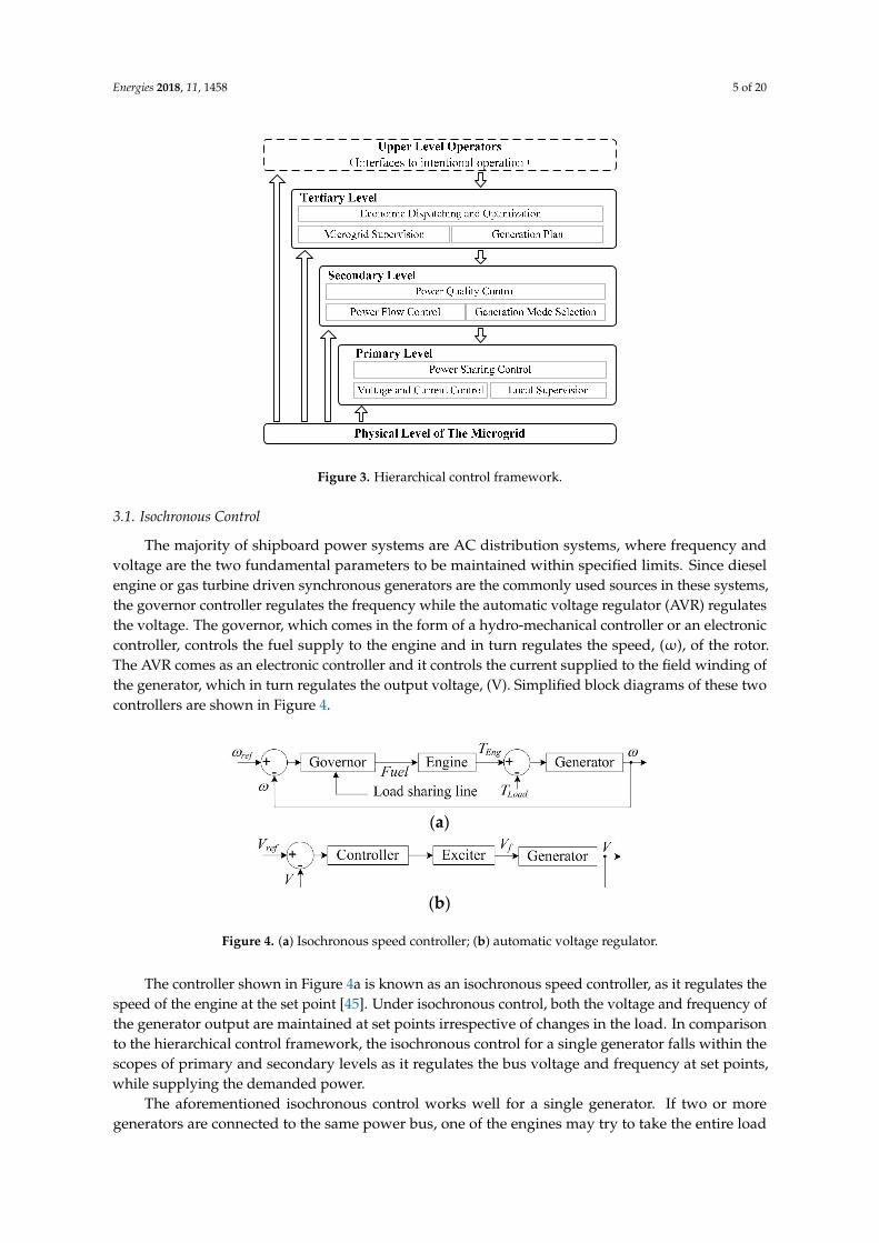
Power generation in ship microgrids is dominated by synchronous generators, which are controllable. However, the loads are highly dynamic and, in certain cases, may contain unpredictable fast changes. Therefore, in order to manage complexities and achieve desired control objectives, the hierarchical framework, which is shown in Figure 3, can be adopted forship microgrids as well [25,44]. Moreover, as explained below, the existing control technologies in ship power systems can also be described in line with the hierarchical control framework. In hierarchical control, the primary level objective is to achieve load sharing among the power sources. The secondary level control objective is to secure bus signals at their nominal values. The tertiary level control is used to achieve optimal operation with intentional objectives [26]. In this scheme, the higher the level of control, the slower the regulation it provides. Moreover, the scope of the control widens as the level increases.
Figure 2. Notional AC zonal electrical distribution system.
Ship power systems are generally ungrounded. This is to limit the risk of system collapse in theevent of a single fault. Nevertheless, HV systems inevitably lead to the increased risk of transientovervoltage due to a phase-to-earth arc flash. Therefore, instead of ungrounded systems, ships withHV distribution systems use high resistance grounding [43].
3. Control Technologies
Power generation in ship microgrids is dominated by synchronous generators, which arecontrollable. However, the loads are highly dynamic and, in certain cases, may contain unpredictablefast changes. Therefore, in order to manage complexities and achieve desired control objectives, thehierarchical framework, which is shown in Figure 3, can be adopted forship microgrids as well [25,44].Moreover, as explained below, the existing control technologies in ship power systems can also bedescribed in line with the hierarchical control framework. In hierarchical control, the primary levelobjective is to achieve load sharing among the power sources. The secondary level control objectiveis to secure bus signals at their nominal values. The tertiary level control is used to achieve optimaloperation with intentional objectives [26]. In this scheme, the higher the level of control, the slower theregulation it provides. Moreover, the scope of the control widens as the level increases.
Energies 2018, 11, 1458 5 of 20
Energies 2018, 11, x FOR PEER REVIEW 5 of 20
Figure 3. Hierarchical control framework.
3.1. Isochronous Control
The majority of shipboard power systems are AC distribution systems, where frequency and voltage are the two fundamental parameters to be maintained within specified limits. Since diesel engine or gas turbine driven synchronous generators are the commonly used sources in these systems, the governor controller regulates the frequency while the automatic voltage regulator (AVR) regulates the voltage. The governor, which comes in the form of a hydro-mechanical controller or an electronic controller, controls the fuel supply to the engine and in turn regulates the speed, (ω), of the rotor. The AVR comes as an electronic controller and it controls the current supplied to the field winding of the generator, which in turn regulates the output voltage, (V). Simplified block diagrams of these two controllers are shown in Figure 4.
(a)
(b)
Figure 4. (a) Isochronous speed controller; (b) automatic voltage regulator.
The controller shown in Figure 4a is known as an isochronous speed controller, as it regulates the speed of the engine at the set point [45]. Under isochronous control, both the voltage and frequency of the generator output are maintained at set points irrespective of changes in the load. In comparison to the hierarchical control framework, the isochronous control for a single generator falls within the scopes of primary and secondary levels as it regulates the bus voltage and frequency at set points, while supplying the demanded power.
The aforementioned isochronous control works well for a single generator. If two or more generators are connected to the same power bus, one of the engines may try to take the entire load while the others might not take the load. This leads to instabilities and may result in blackout. Therefore, in order to solve this issue, communication between the governor controllers, in the form of a load sharing line or a communication link, such as controller area network (CAN) bus or Field bus, is required [46]. With the help of the communication link, each engine can be set to take a specific share of the load without going into extremes or instabilities. In this configuration, the power
Figure 3. Hierarchical control framework.
3.1. Isochronous Control
The majority of shipboard power systems are AC distribution systems, where frequency andvoltage are the two fundamental parameters to be maintained within specified limits. Since dieselengine or gas turbine driven synchronous generators are the commonly used sources in these systems,the governor controller regulates the frequency while the automatic voltage regulator (AVR) regulatesthe voltage. The governor, which comes in the form of a hydro-mechanical controller or an electroniccontroller, controls the fuel supply to the engine and in turn regulates the speed, (ω), of the rotor.The AVR comes as an electronic controller and it controls the current supplied to the field winding ofthe generator, which in turn regulates the output voltage, (V). Simplified block diagrams of these twocontrollers are shown in Figure 4.
Energies 2018, 11, x FOR PEER REVIEW 5 of 20
Figure 3. Hierarchical control framework.
3.1. Isochronous Control
The majority of shipboard power systems are AC distribution systems, where frequency and voltage are the two fundamental parameters to be maintained within specified limits. Since diesel engine or gas turbine driven synchronous generators are the commonly used sources in these systems, the governor controller regulates the frequency while the automatic voltage regulator (AVR) regulates the voltage. The governor, which comes in the form of a hydro-mechanical controller or an electronic controller, controls the fuel supply to the engine and in turn regulates the speed, (ω), of the rotor. The AVR comes as an electronic controller and it controls the current supplied to the field winding of the generator, which in turn regulates the output voltage, (V). Simplified block diagrams of these two controllers are shown in Figure 4.
(a)
(b)
Figure 4. (a) Isochronous speed controller; (b) automatic voltage regulator.
The controller shown in Figure 4a is known as an isochronous speed controller, as it regulates the speed of the engine at the set point [45]. Under isochronous control, both the voltage and frequency of the generator output are maintained at set points irrespective of changes in the load. In comparison to the hierarchical control framework, the isochronous control for a single generator falls within the scopes of primary and secondary levels as it regulates the bus voltage and frequency at set points, while supplying the demanded power.
The aforementioned isochronous control works well for a single generator. If two or more generators are connected to the same power bus, one of the engines may try to take the entire load while the others might not take the load. This leads to instabilities and may result in blackout. Therefore, in order to solve this issue, communication between the governor controllers, in the form of a load sharing line or a communication link, such as controller area network (CAN) bus or Field bus, is required [46]. With the help of the communication link, each engine can be set to take a specific share of the load without going into extremes or instabilities. In this configuration, the power
Figure 4. (a) Isochronous speed controller; (b) automatic voltage regulator.
The controller shown in Figure 4a is known as an isochronous speed controller, as it regulates thespeed of the engine at the set point [45]. Under isochronous control, both the voltage and frequency ofthe generator output are maintained at set points irrespective of changes in the load. In comparisonto the hierarchical control framework, the isochronous control for a single generator falls within thescopes of primary and secondary levels as it regulates the bus voltage and frequency at set points,while supplying the demanded power.
The aforementioned isochronous control works well for a single generator. If two or moregenerators are connected to the same power bus, one of the engines may try to take the entire load

Energies 2018, 11, 1458 6 of 20
while the others might not take the load. This leads to instabilities and may result in blackout.Therefore, in order to solve this issue, communication between the governor controllers, in the form ofa load sharing line or a communication link, such as controller area network (CAN) bus or Field bus, isrequired [46]. With the help of the communication link, each engine can be set to take a specific shareof the load without going into extremes or instabilities. In this configuration, the power managementsystem (PMS), which determines the power reference for each engine, can be attributed to the tertiarylevel of the hierarchical control framework.
Even though isochronous load sharing is capable of regulating voltage and frequency at set points,it has not become the popular choice in ship microgrids, mainly due the harshness of the environmentin ships, which adversely affects communications. Moreover, in order to implement isochronous powersharing, all the governor controllers should be compatible, and most of the cases should come from thesame manufacturer, which may not be possible in some cases. Even though solutions such as advancedgenerator supervision (AGS) have been developed to prevent blackout in faulty situations, isochronouscontrol is still not the popular choice when it comes to very large shipboard power systems [47].
3.2. Droop Control
Compared to isochronous control, droop control is the popular choice for power sharing inmulti-generator shipboard power systems, as it does not require communication between the governorcontrollers. In contrast to the fixed frequency and fixed voltage operation in the isochronous control,droop control lets the frequency and voltage vary in proportion to the active, (P), and reactivepower, (Q), demands of the load. The corresponding speed and voltage controllers are shown inFigure 5, where the speed and voltage references are reduced linearly as the active and reactive powerdemands increase.
Energies 2018, 11, x FOR PEER REVIEW 6 of 20
management system (PMS), which determines the power reference for each engine, can be attributed to the tertiary level of the hierarchical control framework.
Even though isochronous load sharing is capable of regulating voltage and frequency at set points, it has not become the popular choice in ship microgrids, mainly due the harshness of the environment in ships, which adversely affects communications. Moreover, in order to implement isochronous power sharing, all the governor controllers should be compatible, and most of the cases should come from the same manufacturer, which may not be possible in some cases. Even though solutions such as advanced generator supervision (AGS) have been developed to prevent blackout in faulty situations, isochronous control is still not the popular choice when it comes to very large shipboard power systems [47].
3.2. Droop Control
Compared to isochronous control, droop control is the popular choice for power sharing in multi-generator shipboard power systems, as it does not require communication between the governor controllers. In contrast to the fixed frequency and fixed voltage operation in the isochronous control, droop control lets the frequency and voltage vary in proportion to the active, (P), and reactive power, (Q), demands of the load. The corresponding speed and voltage controllers are shown in Figure 5, where the speed and voltage references are reduced linearly as the active and reactive power demands increase.
(a)
(b)
Figure 5. Engine-generator control system (a) speed droop and (b) voltage droop.
The droop control matches with the inherent P/f droop nature of synchronous machines where loads on the electrical side slows down the rotor and as a result, speed drops [48]. The governor injects more fuel in response to the speed drop and thus, as shown in Figure 6a, the genset becomes stable at a new frequency, which is lower than the nominal frequency, f0. Not only the frequency but also the voltage settles at a new value in the same way when there is a change in the reactive power demand [45]. In a multi generator system, each governor senses the speed drop, supplies more power to the grid and finally settles at a new frequency. The amount of power supplied by each genset depends on the droop settings of the genset. If the settings are equal, all the generators equally share the load. Moreover, the droop control can be applied for power converter based systems as well. However, irrespective of the system, droop based power sharing falls within the scope of the primary response in the hierarchical control scheme [48].
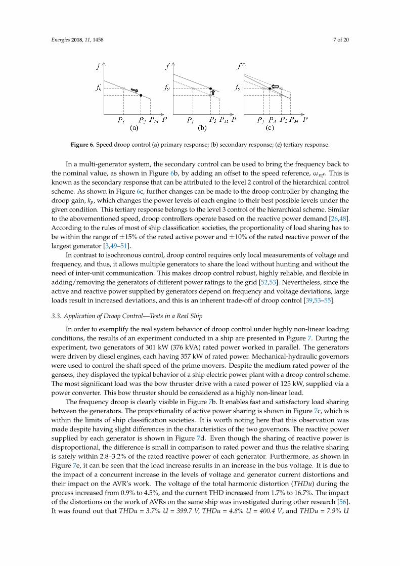
Figure 6. Speed droop control (a) primary response; (b) secondary response; (c) tertiary response.
Figure 5. Engine-generator control system (a) speed droop and (b) voltage droop.
The droop control matches with the inherent P/f droop nature of synchronous machines whereloads on the electrical side slows down the rotor and as a result, speed drops [48]. The governorinjects more fuel in response to the speed drop and thus, as shown in Figure 6a, the genset becomesstable at a new frequency, which is lower than the nominal frequency, f0. Not only the frequencybut also the voltage settles at a new value in the same way when there is a change in the reactivepower demand [45]. In a multi generator system, each governor senses the speed drop, supplies morepower to the grid and finally settles at a new frequency. The amount of power supplied by each gensetdepends on the droop settings of the genset. If the settings are equal, all the generators equally sharethe load. Moreover, the droop control can be applied for power converter based systems as well.However, irrespective of the system, droop based power sharing falls within the scope of the primaryresponse in the hierarchical control scheme [48].
Energies 2018, 11, 1458 7 of 20
Energies 2018, 11, x FOR PEER REVIEW 6 of 20
management system (PMS), which determines the power reference for each engine, can be attributed to the tertiary level of the hierarchical control framework.
Even though isochronous load sharing is capable of regulating voltage and frequency at set points, it has not become the popular choice in ship microgrids, mainly due the harshness of the environment in ships, which adversely affects communications. Moreover, in order to implement isochronous power sharing, all the governor controllers should be compatible, and most of the cases should come from the same manufacturer, which may not be possible in some cases. Even though solutions such as advanced generator supervision (AGS) have been developed to prevent blackout in faulty situations, isochronous control is still not the popular choice when it comes to very large shipboard power systems [47].
3.2. Droop Control
Compared to isochronous control, droop control is the popular choice for power sharing in multi-generator shipboard power systems, as it does not require communication between the governor controllers. In contrast to the fixed frequency and fixed voltage operation in the isochronous control, droop control lets the frequency and voltage vary in proportion to the active, (P), and reactive power, (Q), demands of the load. The corresponding speed and voltage controllers are shown in Figure 5, where the speed and voltage references are reduced linearly as the active and reactive power demands increase.
(a)
(b)
Figure 5. Engine-generator control system (a) speed droop and (b) voltage droop.
The droop control matches with the inherent P/f droop nature of synchronous machines where loads on the electrical side slows down the rotor and as a result, speed drops [48]. The governor injects more fuel in response to the speed drop and thus, as shown in Figure 6a, the genset becomes stable at a new frequency, which is lower than the nominal frequency, f0. Not only the frequency but also the voltage settles at a new value in the same way when there is a change in the reactive power demand [45]. In a multi generator system, each governor senses the speed drop, supplies more power to the grid and finally settles at a new frequency. The amount of power supplied by each genset depends on the droop settings of the genset. If the settings are equal, all the generators equally share the load. Moreover, the droop control can be applied for power converter based systems as well. However, irrespective of the system, droop based power sharing falls within the scope of the primary response in the hierarchical control scheme [48].
Figure 6. Speed droop control (a) primary response; (b) secondary response; (c) tertiary response. Figure 6. Speed droop control (a) primary response; (b) secondary response; (c) tertiary response.
In a multi-generator system, the secondary control can be used to bring the frequency back tothe nominal value, as shown in Figure 6b, by adding an offset to the speed reference, ωref. This isknown as the secondary response that can be attributed to the level 2 control of the hierarchical controlscheme. As shown in Figure 6c, further changes can be made to the droop controller by changing thedroop gain, kp, which changes the power levels of each engine to their best possible levels under thegiven condition. This tertiary response belongs to the level 3 control of the hierarchical scheme. Similarto the abovementioned speed, droop controllers operate based on the reactive power demand [26,48].According to the rules of most of ship classification societies, the proportionality of load sharing has tobe within the range of ±15% of the rated active power and ±10% of the rated reactive power of thelargest generator [3,49–51].
In contrast to isochronous control, droop control requires only local measurements of voltage andfrequency, and thus, it allows multiple generators to share the load without hunting and without theneed of inter-unit communication. This makes droop control robust, highly reliable, and flexible inadding/removing the generators of different power ratings to the grid [52,53]. Nevertheless, since theactive and reactive power supplied by generators depend on frequency and voltage deviations, largeloads result in increased deviations, and this is an inherent trade-off of droop control [39,53–55].
3.3. Application of Droop Control—Tests in a Real Ship
In order to exemplify the real system behavior of droop control under highly non-linear loadingconditions, the results of an experiment conducted in a ship are presented in Figure 7. During theexperiment, two generators of 301 kW (376 kVA) rated power worked in parallel. The generatorswere driven by diesel engines, each having 357 kW of rated power. Mechanical-hydraulic governorswere used to control the shaft speed of the prime movers. Despite the medium rated power of thegensets, they displayed the typical behavior of a ship electric power plant with a droop control scheme.The most significant load was the bow thruster drive with a rated power of 125 kW, supplied via apower converter. This bow thruster should be considered as a highly non-linear load.
The frequency droop is clearly visible in Figure 7b. It enables fast and satisfactory load sharingbetween the generators. The proportionality of active power sharing is shown in Figure 7c, which iswithin the limits of ship classification societies. It is worth noting here that this observation wasmade despite having slight differences in the characteristics of the two governors. The reactive powersupplied by each generator is shown in Figure 7d. Even though the sharing of reactive power isdisproportional, the difference is small in comparison to rated power and thus the relative sharingis safely within 2.8–3.2% of the rated reactive power of each generator. Furthermore, as shown inFigure 7e, it can be seen that the load increase results in an increase in the bus voltage. It is due tothe impact of a concurrent increase in the levels of voltage and generator current distortions andtheir impact on the AVR’s work. The voltage of the total harmonic distortion (THDu) during theprocess increased from 0.9% to 4.5%, and the current THD increased from 1.7% to 16.7%. The impactof the distortions on the work of AVRs on the same ship was investigated during other research [56].It was found out that THDu = 3.7% U = 399.7 V, THDu = 4.8% U = 400.4 V, and THDu = 7.9% U

Energies 2018, 11, 1458 8 of 20
= 401.9 V. Thus, reactive load sharing by droop control can be adversely affected by voltage andcurrent distortions.
Energies 2018, 11, x FOR PEER REVIEW 7 of 20
(a)
(b)
(c)
0
40
80
120
160
P1 P2
[kW]
time [s] 6500
49.6
49.8
50
50.2
50.4
f [Hz]
time [s] 650 0
-2
-1
0
1
2
time [s] 650 0
δP [%]
(d)
0
20
40
60
Q1
Q2
time [s] 0 650
[kVAR]
393
395
397
399
time [s] 650 0
U [V]
(e)
Figure 7. Variations of the basic parameters when two generators are running in parallel: (a) activepower; (b) frequency; (c) proportionality of active power sharing; (d) reactive power; (e) voltage onmain bus bars.

Energies 2018, 11, 1458 9 of 20
3.4. Grid-feeding Power Converter Control
As discussed in the introductory section, the ever growing trend for low emission technologiesand the demarcation of the emission controlled areas (ECAs) resulted in a trend to incorporatemore renewable energy technologies, such as fuel cells, photovoltaic (PV) power systems, windenergy conversion systems, and energy storage technologies such as batteries and supercapacitors [4].Nevertheless, due to relatively low power levels these technologies cannot perform as grid-formingsources. Therefore, the corresponding grid connecting inverters are often used as a grid feedingconverter where the converter injects a specific amount of power to the grid depending on the outputof the maximum power point tracking algorithm [57] or the command from the ship PMS [48]. Currentcontrol is preferred in this mode of operation and thus the interfacing converter can be consideredas a current source. Batteries and supercapacitors are used to absorb power fluctuations and thusthey work mostly at transient conditions. Therefore, their power reference is generally derived fromvoltage/frequency stabilization algorithms.
A typical grid-feeding converter controller block diagram is shown in Figure 8. The innercontroller consists of a fast current control loop that regulates the current, i, injected into the grid andthus the power delivered to the objectives [48,53]. The synchronous reference frame based dq-framecontrol is often used in these inner current control loops. Nevertheless, unbalanced grid conditionsand the presence of harmonics degrades the performance of the synchronous reference based control.Proportional resonant (PR) controllers solve the harmonic issue with properly tuned resonant tosuppress the effects of harmonics [58]. Moreover, the natural reference frame (abc) based controllers,realized in the form of proportional integral (PI), PR, and hysteresis for dead-beats, can be used tocontrol the grid feeding converter [59].
Energies 2018, 11, x FOR PEER REVIEW 9 of 20
A typical grid-feeding converter controller block diagram is shown in Figure 8. The inner controller consists of a fast current control loop that regulates the current, , injected into the grid and thus the power delivered to the objectives [48,53]. The synchronous reference frame based dq-frame control is often used in these inner current control loops. Nevertheless, unbalanced grid conditions and the presence of harmonics degrades the performance of the synchronous reference based control. Proportional resonant (PR) controllers solve the harmonic issue with properly tuned resonant to suppress the effects of harmonics [58]. Moreover, the natural reference frame (abc) based controllers, realized in the form of proportional integral (PI), PR, and hysteresis for dead-beats, can be used to control the grid feeding converter [59].
dLiω
qd Liv ω−
Figure 8. Grid feeding inverter controller.
4. Power Management Optimization
Ship PMS plays a vital role in maintaining the power balance, improving fuel efficiency, preventing blackouts, and ensuring safe operation at various operating conditions. The broader scope of the PMS includes power saving, control of propulsion machinery, control of main and emergency generators, loading and unloading of generator alternator sets, load dependent start/stop, load sharing, load shedding, motors automatic blocking, power and frequency control, synchronizing, and monitoring and load analysis illustration. These functionalities fall within the secondary, tertiary, and upper level control of the aforementioned hierarchical control scheme. Some of these functions are explained in detail below.
• Energy saving: Energy savings can be presented in the three following ways: reduction in specific fuel consumption (SFC), reduction in propulsion fuel consumption, and reduction in overall vessel fuel consumption.
• Automatic start/stop/standby of auxiliary generators: Generators are operated depending on power consumption. A surplus of available power should be limited as much as possible from safety point of view. The PMS constantly compares the total generator load against the load dependent automatic start/stop limits. If the available power minus safety margin is less than the required power, either due to increase in load or fault in a running generator set, the PMS will automatically start the next standby generator set in the start sequence. When the load decreases to a level that will not overload the remaining generators, the standby generator will stop and disconnect.
• Automatic load sharing: When the load increases, another generator is connected to the switchboard. PMS divides the load in an optimal manner on generators after synchronizing.
• Load shedding: When a sudden loss of a generator or load increase occurs, leading to an overload of other generators, non-essential loads are automatically disconnected by the PMS. For example, thrusters can operate with reduced load in dynamic positioning for a period of time because of the slow response of the ship with respect to position and handling. This period is sufficient to get the next unit on-line and increase the power generating capacity. According to [50], the PMS “is to prevent overloading of the generators and maintain power to the essential loads such as propulsion load by shedding non-essential loads.”
• Automatic synchronizing and system restoration: Automatic synchronizing is performed in order to ensure generators are running at required speed, voltage, and phase. After a blackout, the system is required to follow the sequence control of a start-up and reconfiguration of the
Figure 8. Grid feeding inverter controller.
4. Power Management Optimization
Ship PMS plays a vital role in maintaining the power balance, improving fuel efficiency, preventingblackouts, and ensuring safe operation at various operating conditions. The broader scope of the PMSincludes power saving, control of propulsion machinery, control of main and emergency generators,loading and unloading of generator alternator sets, load dependent start/stop, load sharing, loadshedding, motors automatic blocking, power and frequency control, synchronizing, and monitoringand load analysis illustration. These functionalities fall within the secondary, tertiary, and upper levelcontrol of the aforementioned hierarchical control scheme. Some of these functions are explained indetail below.
• Energy saving: Energy savings can be presented in the three following ways: reduction in specificfuel consumption (SFC), reduction in propulsion fuel consumption, and reduction in overallvessel fuel consumption.
• Automatic start/stop/standby of auxiliary generators: Generators are operated depending onpower consumption. A surplus of available power should be limited as much as possible fromsafety point of view. The PMS constantly compares the total generator load against the loaddependent automatic start/stop limits. If the available power minus safety margin is less than

Energies 2018, 11, 1458 10 of 20
the required power, either due to increase in load or fault in a running generator set, the PMSwill automatically start the next standby generator set in the start sequence. When the loaddecreases to a level that will not overload the remaining generators, the standby generator willstop and disconnect.
• Automatic load sharing: When the load increases, another generator is connected to theswitchboard. PMS divides the load in an optimal manner on generators after synchronizing.
• Load shedding: When a sudden loss of a generator or load increase occurs, leading to an overloadof other generators, non-essential loads are automatically disconnected by the PMS. For example,thrusters can operate with reduced load in dynamic positioning for a period of time because ofthe slow response of the ship with respect to position and handling. This period is sufficient toget the next unit on-line and increase the power generating capacity. According to [50], the PMS“is to prevent overloading of the generators and maintain power to the essential loads such aspropulsion load by shedding non-essential loads.”
• Automatic synchronizing and system restoration: Automatic synchronizing is performed in orderto ensure generators are running at required speed, voltage, and phase. After a blackout, thesystem is required to follow the sequence control of a start-up and reconfiguration of the powersystem, which includes starting and synchronizing generator sets and sequential starts of loads.
• Monitoring and load analysis illustration: The PMS consist of a monitoring system to monitorthe load profile, active and reactive load sharing monitoring to monitor the load sharing failure,fuel consumption monitoring, graphically displayed information that can help operators to targetwasted energy, and engine performance monitoring. Additionally, some PMS monitoring systemsprovide historical data to help make decisions on the maintenance and operation of machineryand other ship power system components [48].
• Load transfer: The PMS can control and monitor the load transfer from shaft to auxiliary and viceversa in hybrid electric ships, and shore power to auxiliary in cold ironing [60].
The load type and condition plays a vital role in determining the efficiency of power managementfor vessels. Hence, the appropriate PMS can be fitted based on the types of loads present onboardthe ship and their dynamics. For tanker ships, pumps and compressors are significant factors asthey consume a significant portion of the generated power. In cruise ships, approximately 50% oftotal fuel consumption is consumed by hotel loads such as air conditioning systems, heating systems,galley equipment, stage equipment, and lights. For container ships, cargo handling equipment playsa dominant role and defines the special power requirement characteristics of the installed powersystem onboard. Moreover, in certain vessels, ballast water pumps present a large load on the shippower system.
Similar to the terrestrial microgrids, power management in a ship’s microgrid can also beimplemented in centralized or decentralized manners. A centralized management system requirescomputation resources and data gathered from internal microgrid components in the case of anislanded microgrid, and from external components in the case of a grid connected microgrid.Centralized PMS, used to achieve the minimum operational costs with efficient operation, gives theadvantages of wide observation of the whole system and this type of system is easy to implement [61].However, a single point of failure in the centralized PMS will affect the entire system [62]. On the otherhand, decentralized PMS is preferred when more flexibility in operation and a non-single point offailure system is required. Due to the dynamic nature and finite generation inertia associated withIPSs, decentralized PMS is preferred to achieve the balance between generation and load in real timewhile satisfying the operational constraints [63–65].
With the incorporation of alternative energy technologies, energy recovery technologies,and energy storage systems, ship PMS becomes a key element in optimizing energy usage andthereby improving fuel efficiency. In contrast to terrestrial microgrids, there are many constraintsassociated with the optimization of ship PMS as it is heavily influenced by dynamic loads [66].

Energies 2018, 11, 1458 11 of 20
Moreover, the objectives of the optimal power management for ship microgrids depend on theoperating conditions of the ship, which can be generally classified into emergency, alert, restorative,reconfigurative, cruise, acceleration, deceleration, and docking [25,67].
Researchers have proposed various optimal power management techniques using classicaland meta-heuristic optimization methods by considering the minimization of operational costs andgreenhouse gas emissions as their main objective function [68–71]. In [11], the authors have proposeda model predictive control (MPC) based energy management strategy in order to optimally operate thesystem by dealing with power ramp rate problems for all-electric ships (AES). The proposed hybridEMS is a combination of heuristics and MPC in which heuristics are applied to distinguish the system’sstate transitions and MPC is applied to fulfill the control objective function in each state. Anotherstudy, reported in [72], proposed an adaptive MPC for AES energy management, which providesbetter energy management compared to the use of MPC alone. In [73], the authors have proposed amulti-objective optimization with real-time MPC for electric ships. The results revealed that the useof the proposed method provides less energy storage losses than MPC. In [74], authors proposed afuzzy-based particle swarm optimization (FPSO) as a power management strategy for ship electricpower systems, comprising integrated full electric propulsion, energy storage, and shore power supply.The main multi-objective function of the optimization is to minimize operating cost and greenhousegas emissions. The proposed method provides better results in terms of minimum operational costsand greenhouse gas emissions compared to conventional PSO. In other studies, Genetic Algorithm(GA) is used to solve optimization problems including reconfiguration and restoration in ship powersystems [75,76]. In other studies, trim optimization is used to reduce the fuel cost and emissionsby minimizing fuel consumption [77]. Moreover, LINDO optimization software is used to achieverestoration in ship power system by maximizing the restored load and giving priority to vital loads [41].Biogeography based optimization (BBO) and particle swarm optimization (PSO) are other techniquesthat can be used in ship microgrids. Out of these methods, GA has been recognized as a more reliablesolution for optimal DC voltage and power control in medium voltage DC (MVDC) shipboard powersystems [78]. Another study reported in [79] proposed a real-time optimization based on PSO tooptimally manage the power of notional MVDC system for a DC ship microgrid.
The multi-agent system (MAS) technique is one of the most advanced and flexible choices inoptimal control and power management [80–82], where there are multiple agents interacting witheach other in a cooperative manner to solve complex problems effectively [81]. Recent researcheshave revealed that MAS techniques are able to achieve the minimum demand-supply mismatch,while maximizing the capacity of energized loads, by determining the switch statues of loads in DCzones [63,64]. This has further revealed that the system can be operated normally by preventingblackout in the event of a failure in a subsection. In [83], a real-time heterogeneous MAS is proposed tomanage power for AES with a DC zonal system. The study found that incorporating real-time controlmethods with MAS provides better performance than conventional MAS under the frequency loadshedding method. Table 1 summarizes recent developments in power management methods proposedfor ship microgrids.

Energies 2018, 11, 1458 12 of 20
Table 1. Power management methods used in shipboard power systems.
Method Objective Constrains * OperatingCondition
Software/Experimental Ref.
VL F SC PCC PB GL OT GHG SS TD RR BP GSS ESS LL SI CC PG BC
Hybrid heuristicsand MPC based
EMS
Minimizing the cost to managethe energy of storage system
√ √ √ √ Ramp rateconditions
Software andexperimental [11]
Adaptive MPC Maximize system reliability andefficiency
√ √ √ √ √Normal Software [72]
Real-timemulti-objective MPC
Minimize the power trackingerror and storage losses
√ √ √Normal Software [73]
Fuzzy-based PSO(FPSO)
Minimize the operating cost andGHG
√ √ √ √ √Normal Software [74]
Multi- objectivenon-dominatedSorting Genetic
Algorithm II
Minimize the total poweradjustments, individual activepower set-point adjustments andindividual reactive powerset-point adjustments
√ √ √ √Normal/alert Software [20]
Multi-agent
Minimize the mismatch betweengeneration and load and to serveas many higher priority loads aspossible in operational real time
√ √Normal/Emergency Software [63]
Maximize capacity of theenergized loads
√ √Normal/Emergency Software [64]
Real-time PSO Minimize the system’s cost and√ √ Normal and
pulse load Software [79]
Dynamicprogramming Minimize the total variable cost
√ √ √ √ √ √ √ √Cruise ferry Software [68]

Energies 2018, 11, 1458 13 of 20
Table 1. Cont.
Method Objective Constrains * OperatingCondition
Software/Experimental Ref.
VL F SC PCC PB GL OT GHG SS TD RR BP GSS ESS LL SI CC PG BC
Dynamicprogramming and
PSO
Minimum operation cost andGHG emissions limitation
√ √ √ √ √ √ √ √ √Cruise ferry Software [69]
Recursive searchingalgorithm
Minimize fuel cost and GHGemissions limitation
√ √ √ √ √ √Normal Software [70]
Numericalalgorithm Minimize fuel consumption
√ √ Seven operatingconditions
Software andexperimental [84]
FuzzyMulti-objectiveusing adaptive
Generic Algorithm
Maximization of the RestoredLoads Considering the LoadPriorities and Minimization of theNumber of Switch OperationsConsidering the Switch Priorities
√ √ √Restoration Software [75]
GAMaximizing the served load withrespect to load priorities afterfault occurrence
√ √Reconfiguration Software [76]
Real-timeheterogeneous MAS
Maximize the energized loads inthe dc zonal system
√ √ √ Normal andpulse load Software [83]
Reconfigurationalgorithms
Maximizing power delivery andminimizing the number ofswitching actions
√ √ √ √Reconfiguration Software [85]
* Refer to Appendix A.

Energies 2018, 11, 1458 14 of 20
Maintaining reliable and secure communications is important for the operation of ship microgrids,especially with decentralized power management and control. Moreover, the communication betweendevices is time-critical and thus associated algorithms should be able to minimize delay and reducecomputational complexity [86]. These requirements are very similar to those of the terrestrialmicrogrids and thus the communication methods developed for terrestrial microgrids can be extendedfor ship microgrids as well. An example of such a communication method is a security model basedon message authentication code (MAC). This communication method is used for communicationbetween terrestrial microgrid components including network, data, and attack models [87]. This modelprovides a secured communication environment with faster response and less memory comparedwith Rivest, Shamir, and Adleman (RSA), digital signature algorithm (DSA), and time valid hashone-time signature (TV-HORS) [88]. In islanded microgrids, low bandwidth communication is used toexchange information between a centralized controller and local controller in the secondary frequencymicrogrid. Delay margins in communication increase with the increase of gains of the secondaryfrequency controller which can be compensated by using a gain scheduling approach method [89].The above-mentioned communication methods can be implemented in future ship microgrids dueto their improved real-time response in order to ensure high performance and more reliability inship microgrids.
Maintaining a low SFC is also another important objective of emerging ship PMS. Preplannedenergy management by offline optimization algorithm can be used for fuel saving. However, inpractical operation of ships, there are several innumerable contingencies, which influence the vesseloperation. Therefore, using preplanned energy management will result in suboptimal fuel efficiency.In the other hand, the use of real-time energy management and optimization will provide moreefficient fuel minimization [36,90]. Figure 9 shows a typical SFC curve for a marine diesel-engine [84].The optimal fuel consumption can be achieved when the engine load is operated at the minimum SFC.
Energies 2018, 11, x FOR PEER REVIEW 14 of 20
Energies 2018, 11, x; doi: FOR PEER REVIEW www.mdpi.com/journal/energies
Maintaining reliable and secure communications is important for the operation of ship microgrids, especially with decentralized power management and control. Moreover, the communication between devices is time-critical and thus associated algorithms should be able to minimize delay and reduce computational complexity [86]. These requirements are very similar to those of the terrestrial microgrids and thus the communication methods developed for terrestrial microgrids can be extended for ship microgrids as well. An example of such a communication method is a security model based on message authentication code (MAC). This communication method is used for communication between terrestrial microgrid components including network, data, and attack models [87]. This model provides a secured communication environment with faster response and less memory compared with Rivest, Shamir, and Adleman (RSA), digital signature algorithm (DSA), and time valid hash one-time signature (TV-HORS) [88]. In islanded microgrids, low bandwidth communication is used to exchange information between a centralized controller and local controller in the secondary frequency microgrid. Delay margins in communication increase with the increase of gains of the secondary frequency controller which can be compensated by using a gain scheduling approach method [89]. The above-mentioned communication methods can be implemented in future ship microgrids due to their improved real-time response in order to ensure high performance and more reliability in ship microgrids.
Maintaining a low SFC is also another important objective of emerging ship PMS. Preplanned energy management by offline optimization algorithm can be used for fuel saving. However, in practical operation of ships, there are several innumerable contingencies, which influence the vessel operation. Therefore, using preplanned energy management will result in suboptimal fuel efficiency. In the other hand, the use of real-time energy management and optimization will provide more efficient fuel minimization [36,90]. Figure 9 shows a typical SFC curve for a marine diesel-engine [84]. The optimal fuel consumption can be achieved when the engine load is operated at the minimum SFC.
Figure 9. Typical specific fuel consumption curve of a marine diesel-engine.
Practically, the minimum SFC point does not represent the minimum fuel consumption of the engine due to power losses. Engine speed can also effect the SFC value as at high speeds it increases due to the increase in friction. At low speeds, it increases due to increased time for heat losses [91]. In addition, load ripples on the generator can cause ripples on the engine SFC. Therefore, fuel consumption can be optimized by minimizing SFC subjected to operational constraints such as engine speed and load ripple [84]. Energy storage systems can be used to absorb load ripples and thereby reduce SFC. This results in on-board emission reductions [66,92]. Additionally, the utilization of energy storage systems such as batteries is common to restore power system frequency and voltage [93,94]. Moreover, energy storage systems provide a reliable solution to supply multiple pulse loads [95,96].
Figure 9. Typical specific fuel consumption curve of a marine diesel-engine.
Practically, the minimum SFC point does not represent the minimum fuel consumption of theengine due to power losses. Engine speed can also effect the SFC value as at high speeds it increasesdue to the increase in friction. At low speeds, it increases due to increased time for heat losses [91].In addition, load ripples on the generator can cause ripples on the engine SFC. Therefore, fuelconsumption can be optimized by minimizing SFC subjected to operational constraints such as enginespeed and load ripple [84]. Energy storage systems can be used to absorb load ripples and therebyreduce SFC. This results in on-board emission reductions [66,92]. Additionally, the utilization of energystorage systems such as batteries is common to restore power system frequency and voltage [93,94].Moreover, energy storage systems provide a reliable solution to supply multiple pulse loads [95,96].

Energies 2018, 11, 1458 15 of 20
5. Concluding Remarks and Future Trends in Ship Microgrids
With the growing demand for low emissions and fuel efficiency improvements in the maritimeindustry, alternative energy sources and energy storage technologies are becoming popular in shipmicrogrids. This paper presents a review on ship microgrid architectures, control technologies, andrecent developments in power management strategies. In addition, the author’s original research onthe performance of droop control based power sharing is presented.
The growing interest for incorporating more-electric technologies into ships increases the demandfor electrical power. Therefore, in large ships, HVAC distribution is preferred over LVAC distribution.Moreover, compared to radial architecture, ZEDS architectures are becoming popular in ship microgridsmainly due to their ability to prevent blackouts during faults in certain sections. Nowadays,the integration of renewable energy sources and energy storage systems is gaining attention dueto the growing demand for emission reductions and fuel efficiency improvements. This trend ismainly supported by advancements in associated power electronics converter technologies. Moreover,energy storage systems are used to smoothen severe load transients and thereby obtain a morestable and secure shipboard power system. Hence, the ship microgrid can achieve power systemstability by balancing demand and supply in real time while satisfying operational constraints.Moreover, with the advancements in power electronic technologies, the trend toward using DCdistribution systems on-board is becoming popular [2]. One common recommended design is themedium voltage DC (MVDC) distribution system, with a voltage range of 1 kV to 35 kV [97]. This ismainly due to several advantages that DC distribution systems offer over AC distribution, includingthe possibility of implementing prime mover speed optimization to reduce fuel consumption andemissions, the flexibility to integrate renewable energy sources and energy storage systems, and theabsence of reactive power and harmonic issues. Therefore, more focus is recommended to be taken ontopics related to DC ship microgrids in future work.
On the control point of view, despite having certain limitations and disadvantages such asvoltage and frequency deviations and the effects of current harmonics on the voltage regulation,droop control will continue to be the popular choice in AC ship microgrids. This is mainly due tothe presence of synchronous generators and HV distribution systems in ships, a combination thatis for droop control. Even though the presence of alternative energy technologies such as PV, wind,and fuel cells in ship microgrids continue to grow, their power levels are relatively small and thusthe corresponding interfacing converters act as grid feeding inverters. Moreover, energy recoverytechnologies such as waste heat recovery are being incorporated into ship microgrids to improve fuelefficiency. The corresponding interfacing converters also work as grid feeding inverters. Once thesegrid feeding inverters are added into a ship microgrid, its control becomes complex. The hierarchicalcontrol framework, which is well explored in relation to complex terrestrial microgrids, can be adoptedto these ship microgrids as well.
In terms of power management optimization, several studies reveal that using meta-heuristicoptimization methods such as PSO and GA provide more promising optimization results than classicalmethods. This can be achieved, as meta-heuristic methods are capable of solving multi-objectiveoptimization problems while satisfying several technical and operational constraints. Moreover,several studies used the MAS technique for the control and power management of shipmicrogrids.It is concluded from studies incorporating real-time control methods with MAS, that this combinationprovides better performance than using conventional MAS alone.
Communication plays a major role in assuring the safe and reliable operation of ship microgrids.In order to achieve these objectives, communication algorithms should be highly reliable, time-critical,and computationally not very complex. Terrestrial microgrids have similar requirements in terms ofcommunications and thus similar methods, developed for terrestrial microgrids, can be adopted forship microgrids.

Energies 2018, 11, 1458 16 of 20
Author Contributions: M.D.A.A.-F., T.T. and S.G.J. wrote the paper; T.T. performed the experiments; H.E., Z.J.and J.M.G. provide guidance and critical review for the work.
Acknowledgments: This work was supported by the National Science Centre, Poland under Grant DEC-2012/07/E/ST8/01688.
Conflicts of Interest: The authors declare no conflict of interest.
Appendix A. Power Management Constraints
VL Voltage limit F FrequencySC Source capacity PCC Power Converter CapacityPB Power Balance OT Operating time of Gen.GHG Greenhouse gas emission SS Ship speedTD Travel distance BP Blackout PreventionRR Ramp Rates GSS Generator start/stopESS Energy Storage System level (charge/discharge) LL Load level/LimitSI Stability index (transient angle stability index) CC Cable/branch currentPG Power Generation limit BC Bus current
References
1. García-Olivares, A.; Solé, J.; Osychenko, O. Transportation in a 100% renewable energy system. EnergyConvers. Manag. 2018, 158, 266–285. [CrossRef]
2. Castellan, S.; Menis, R.; Tessarolo, A.; Luise, F.; Mazzuca, T. A review of power electronics equipment forall-electric ship MVDC power systems. Int. J. Electr. Power Energy Syst. 2018, 96, 306–323. [CrossRef]
3. Skjong, E.; Rødskar, E.; Molinas, M.; Johansen, T.; Cunningham, J. The marine vessel’s electrical powersystem: From its birth to present day. Proc. IEEE 2015, 103, 2410–2424. [CrossRef]
4. Jayasinge, S.; Lokuketagoda, G.; Enshaei, H.; Shagar, V.; Ranmuthugala, D. Electro-technologies for energyefficiency improvement and low carbon emission in maritime transport. In Proceedings of the 16thAnnual General Assembly of the International Association of Maritime Universities, Opatija, Croatia,7–10 October 2015; pp. 119–123.
5. Sciberras, E.A.; Zahawi, B.; Atkinson, D.J. Reducing shipboard emissions—Assessment of the role of electricaltechnologies. Transp. Res. Part D Transp. Environ. 2017, 51, 227–239. [CrossRef]
6. Lan, H.; Dai, J.; Wen, S.; Hong, Y.-Y.; Yu, D.; Bai, Y. Optimal Tilt Angle of Photovoltaic Arrays and EconomicAllocation of Energy Storage System on Large Oil Tanker Ship. Energies 2015, 8, 11515–11530. [CrossRef]
7. Han, J.; Charpentier, J.-F.; Tang, T. An Energy Management System of a Fuel Cell/Battery Hybrid Boat.Energies 2014, 7, 2799–2820. [CrossRef]
8. Geertsma, R.D.; Negenborn, R.R.; Visser, K.; Hopman, J.J. Design and control of hybrid power and propulsionsystems for smart ships: A review of developments. Appl. Energy 2017, 194, 30–54. [CrossRef]
9. Andreasen, J.; Meroni, A.; Haglind, F. A Comparison of Organic and Steam Rankine Cycle Power Systemsfor Waste Heat Recovery on Large Ships. Energies 2017, 10, 547. [CrossRef]
10. Shagar, V.; Jayasinghe, S.G.; Enshaei, H. Effect of load changes on hybrid shipboard power systems andenergy storage as a potential solution: A review. Inventions 2017, 2, 21. [CrossRef]
11. Vu, T.V.; Gonsoulin, D.; Diaz, F.; Edrington, C.S.; El-Mezyani, T. Predictive Control for Energy Management in ShipPower Systems Under High-Power Ramp Rate Loads. IEEE Trans. Energy Convers. 2017, 32, 788–797. [CrossRef]
12. Gonsoulin, D.; Vu, T.; Diaz, F.; Vahedi, H.; Perkins, D.; Edrington, C. Centralized MPC for Multiple EnergyStorages in Ship Power Systems. In Proceedings of the IECON 2017-43rd Annual Conference of the IEEEIndustrial Electronics Society, Beijing, China, 29 October–1 November 2017.
13. Gonsoulin, D.E.; Vu, T.V.; Diaz, F.; Vahedi, H.; Perkins, D.; Edrington, C.S. Coordinating Multiple EnergyStorages Using MPC for Ship Power Systems. In Proceedings of the 2017 IEEE Electric Ship TechnologiesSymposium (ESTS), Arlington, VA, USA, 14–17 August 2017.
14. Crider, J.M.; Sudhoff, S.D. Reducing impact of pulsed power loads on microgrid power systems. IEEE Trans.Smart Grid 2010, 1, 270–277. [CrossRef]

Energies 2018, 11, 1458 17 of 20
15. Kelley, J.P.; Wetz, D.A.; Reed, J.A.; Cohen, I.J.; Turner, G.K.; Lee, W.-J. The impact of power quality whenhigh power pulsed DC and continuous AC loads are simultaneously operated on a MicroGrid testbed.In Proceedings of the 2013 IEEE Electric Ship Technologies Symposium (ESTS), Arlington, VA, USA, 22–24April 2013; pp. 6–12.
16. Hebner, R.E.; Davey, K.; Herbst, J.; Hall, D.; Hahne, J.; Surls, D.D.; Ouroua, A. Dynamic load and storageintegration. Proc. IEEE 2015, 103, 2344–2354. [CrossRef]
17. Hou, J.; Sun, J.; Hofmann, H. Control development and performance evaluation for battery/flywheel hybridenergy storage solutions to mitigate load fluctuations in all-electric ship propulsion systems. Appl. Energy2018, 212, 919–930. [CrossRef]
18. McCoy, T.J. Electric Ships Past, Present, and Future [Technology Leaders]. IEEE Electrification Mag. 2015, 3,4–11. [CrossRef]
19. Sudhoff, S.D.; Pekarek, S.D.; Swanson, R.R.; Duppalli, V.S.; Horvath, D.C.; Kasha, A.E.; Lin, R.; Marquet, B.D.;O’Regan, P.R.; Suryanarayana, H.; Yan, Y. A Reduced Scale Naval DC Microgrid to Support Electric ShipResearch and Development. In Proceedings of the 2015 IEEE Electric Ship Technologies Symposium (ESTS),Alexandria, VA, USA, 21–24 June 2015; pp. 464–471.
20. Mashayekh, S.; Butler-Purry, K.L. An Integrated Security-Constrained Model-Based Dynamic PowerManagement Approach for Isolated Microgrids in All-Electric Ships. IEEE Trans. Power Syst. 2015, 30,2934–2945. [CrossRef]
21. Elsayed, A.T.; Mohamed, A.A.; Mohammed, O.A. DC microgrids and distribution systems: An overview.Electr. Power Syst. Res. 2015, 119, 407–417. [CrossRef]
22. Al-Falahi, M.D.; Jayasinghe, S.; Enshaei, H. A review on recent size optimization methodologies for standalonesolar and wind hybrid renewable energy system. Energy Convers. Manag. 2017, 143, 252–274. [CrossRef]
23. Al-Falahi, M.D.; Nimma, K.S.; Jayasinghe, S.; Enshaei, H. Sizing and modeling of a standalone hybridrenewable energy system. In Proceedings of the IEEE Annual Southern Power Electronics Conference(SPEC), Auckland, New Zealand, 5–8 December 2016; pp. 1–6.
24. Jayasinghe, S.G.; Meegahapola, L.; Fernando, N.; Jin, Z.; Guerrero, J.M. Review of ship microgrids: Systemarchitectures, storage technologies and power quality aspects. Inventions 2017, 2, 4. [CrossRef]
25. Jin, Z.; Savaghebi, M.; Vasquez, J.C.; Meng, L.; Guerrero, J.M. Maritime DC Microgrids-A Combination ofMicrogrid Technologies and Maritime Onboard Power System for Future Ships. In Proceedings of the 20168th International Power Electronics and Motion Control Conference-Ecce Asia (IPEMC 2016-ECCE Asia),Hefei, China, 22–26 May 2016.
26. Guerrero, J.M.; Vasquez, J.C.; Matas, J.; De Vicuña, L.G.; Castilla, M. Hierarchical control of droop-controlledAC and DC microgrids—A general approach toward standardization. IEEE Trans. Ind. Electron. 2011, 58,158–172. [CrossRef]
27. Liang, J.; Qi, L.; Lindtjørn, J.O.; Wendt, F. Frequency Dependent DC Voltage Droop Control for HybridEnergy Storage in DC Microgrids. In Proceedings of the 2015 IEEE Power & Energy Society General Meeting,Denver, CO, USA, 26–30 July 2015; pp. 1–5.
28. Farasat, M.; Arabali, A.S.; Trzynadlowski, A.M. A novel control principle for all-electric ship power systems.In Proceedings of the 2013 IEEE Electric Ship Technologies Symposium (ESTS), Arlington, VA, USA,22–24 April 2013; pp. 178–184.
29. Shang, C.; Srinivasan, D.; Reindl, T. Economic and Environmental Generation and Voyage Scheduling ofAll-Electric Ships. IEEE Trans. Power Syst. 2015, 31, 4087–4096. [CrossRef]
30. Nasri, M.; Hossain, M.R.; Ginn, H.L.; Moallem, M. Agent-based real-time coordination of power convertersin a DC shipboard power system. In Proceedings of the 2015 IEEE Electric Ship Technologies Symposium(ESTS), Alexandria, VA, USA, 21–24 June 2015; pp. 8–13.
31. Paran, S.; Vu, T.; El Mezyani, T.; Edrington, C. MPC-based power management in the shipboard powersystem. In Proceedings of the 2015 IEEE Electric Ship Technologies Symposium (ESTS), Alexandria, VA,USA, 21–24 June 2015; pp. 14–18.
32. Tang, D.; Yan, X.; Yuan, Y.; Wang, K.; Qiu, L. Multi-agent Based Power and Energy Management Systemfor Hybrid Ships. In Proceedings of the 2015 International Conference on Renewable Energy Research andApplications (ICRERA), Palermo, Italy, 22–25 November 2015; pp. 383–387.

Energies 2018, 11, 1458 18 of 20
33. Shagar, V.; Jayasinghe, S.; Enshaei, H. Frequency Transient Suppression in Hybrid Electric Ship PowerSystems: A Model Predictive Control Strategy for Converter Control with Energy Storage. Inventions 2018, 3,13. [CrossRef]
34. Pish, S.; Herbst, J.; Wardell, D.; Gattozzi, A.; Flynn, M. Power management and energy storage experimentson a MW-scale naval power system test-bed. In Proceedings of the 2015 IEEE Electric Ship TechnologiesSymposium (ESTS), Alexandria, VA, USA, 21–24 June 2015; pp. 453–458.
35. Rose, M.W.; Cuzner, R.M. Fault isolation and reconfiguration in a three-zone system. In Proceedings of the2015 IEEE Electric Ship Technologies Symposium (ESTS), Alexandria, VA, USA, 21–24 June 2015; pp. 409–414.
36. Jin, Z.; Sulligoi, G.; Cuzner, R.; Meng, L.; Vasquez, J.C.; Guerrero, J.M. Next-Generation Shipboard DC PowerSystem: Introduction Smart Grid and dc Microgrid Technologies into Maritime Electrical Netowrks. IEEEElectrification Mag. 2016, 4, 45–57. [CrossRef]
37. Huang, K.; Srivastava, S.K.; Cartes, D.A.; Sun, L.-H. Market-based multiagent system for reconfiguration ofshipboard power systems. Electr. Power Syst. Res. 2009, 79, 550–556. [CrossRef]
38. Hall, D.T. Practical Marine Electrical Knowladge, 3rd ed.; Witherby Seamanship: Livingston, UK, 2014.39. Jin, Z.; Meng, L.; Guerrero, J.M.; Han, R. Hierarchical Control Design for a Shipboard Power System With
DC Distribution and Energy Storage Aboard Future More-Electric Ships. IEEE Trans. Ind. Inform. 2018, 14,703–714. [CrossRef]
40. Hegner, H.; Desai, B. Integrated fight through power. In Proceedings of the 2002 IEEE Power EngineeringSociety Summer Meeting, Chicago, IL, USA, 21–25 July 2002; pp. 336–339.
41. Khushalani, S.; Solanki, J.; Schulz, N. Optimized restoration of combined ac/dc shipboard power systemsincluding distributed generation and islanding techniques. Electr. Power Syst. Res. 2008, 78, 1528–1536.[CrossRef]
42. IEEE Std 45.3™-2015. IEEE Recommended Practice for Shipboard Electrical Installations—Systems Engineering;IEEE: Piscataway, NJ, USA, 2015.
43. Nelson, J.P.; Burns, D.; Seitz, R.; Leoni, A. The grounding of marine power systems: Problems and solutions.In Proceedings of the 2004 Fifty-First Annual Conference Petroleum and Chemical Industry TechnicalConference, San Francisco, CA, USA, 13–15 September 2004; pp. 151–161.
44. Papadimitriou, C.; Zountouridou, E.; Hatziargyriou, N. Review of hierarchical control in DC microgrids.Electr. Power Syst. Res. 2015, 122, 159–167. [CrossRef]
45. Cosse, R.E.; Alford, M.D.; Hajiaghajani, M.; Hamilton, E.R. Turbine/generator governor droop/isochronousfundamentals—A graphical approach. In Proceedings of the 2011 Record of Conference Papers IndustryApplications Society 58th Annual IEEE Petroleum and Chemical Industry Conference (PCIC), Toronto, ON,Canada, 19–21 September 2011; pp. 1–8.
46. Olson, G. Paralleling Dissimilar Generators: Part 3—Load Sharing Compatibility. In White Paper; CumminsPower Generation: Ramsgate, UK, 2010.
47. Johannessen, P.F.; Mathiesen, E. Advanced Failure Detection and Handling in Power Management System.In Proceedings of the Dynamic Positioning Committee, Kongsberg, Norway, 13–14 October 2009.
48. Rocabert, J.; Luna, A.; Blaabjerg, F.; Rodr, P. Control of Power Converters in AC Microgrids. IEEE Trans.Power Electron. 2012, 27, 4734–4749. [CrossRef]
49. DNV-GL. Rules for Classification. Ships. Part 4 Systems and Components; Chapter 8 Electrical Installations;DNV-GL: Oslo, Norway, 2016.
50. International Naval Ships. Part 4 Vessel Systems and Machinery. In Guide for Building and Classing; ABS:Houston, TX, USA, 2016.
51. Register, L.S. Rules and Regulations for Classification of Ships; Lloyd’s Register: London, UK, 2016.52. Vu, T.V.; Perkins, D.; Diaz, F.; Gonsoulin, D.; Edrington, C.S.; El-Mezyani, T. Robust adaptive droop control
for DC microgrids. Electr. Power Syst. Res. 2017, 146, 95–106. [CrossRef]53. Han, H.; Hou, X.; Yang, J.; Wu, J.; Su, M.; Guerrero, J.M. Review of Power Sharing Control Strategies for
Islanding Operation of AC Microgrids. IEEE Trans. Smart Grid 2016, 7, 200–215. [CrossRef]54. Eid, B.M.; Rahim, N.A.; Selvaraj, J.; Khateb, A.H.E. Control Methods and Objectives for Electronically
Coupled Distributed Energy Resources in Microgrids: A Review. IEEE Syst. J. 2016, 10, 446–458. [CrossRef]55. Olivares, D.E.; Mehrizi-Sani, A.; Etemadi, A.H.; Ca, C.A.; Iravani, R.; Kazerani, M.; Hajimiragha, A.H.;
Gomis-Bellmunt, O.; Saeedifard, M.; Palma-Behnke, R.; et al. Trends in Microgrid Control. IEEE Trans. SmartGrid 2014, 5, 1905–1919. [CrossRef]

Energies 2018, 11, 1458 19 of 20
56. Tarasiuk, T.; Pilat, A.; Szweda, M. Experimental Study on Impact of Ship Electric Power Plant Configurationon Power Quality in the Ship Power System. In Proceedings of the Proceedings of the World Congress onEngineering, London, UK, 2–4 July 2014.
57. Liu, Y.; Zhang, Q.; Wang, C.; Wang, N. A control strategy for microgrid inverters based on adaptive three-ordersliding mode and optimized droop controls. Electr. Power Syst. Res. 2014, 117, 192–201. [CrossRef]
58. Cárdenas, R.; Juri, C.; Pena, R.; Wheeler, P.; Clare, J. The Application of Resonant Controllers to Four-Leg MatrixConverters Feeding Unbalanced or Nonlinear Loads. IEEE Trans. Power Electron. 2012, 27, 1120–1129. [CrossRef]
59. Blaabjerg, F.; Teodorescu, R.; Liserre, M.; Timbus, A.V. Overview of Control and Grid Synchronization forDistributed Power Generation Systems. IEEE Trans. Ind. Electron. 2006, 53, 1398–1409. [CrossRef]
60. Jayasinghe, S.G.; Al-Falahi, M.; Enshaei, H.; Fernando, N.; Tashakori, A. Floating power platforms for mobilecold-ironing. In Proceedings of the IEEE Annual Southern Power Electronics Conference (SPEC), Auckland,New Zealand, 5–8 December 2016; pp. 1–5.
61. Palma-Behnke, R.; Benavides, C.; Lanas, F.; Severino, B.; Reyes, L.; Llanos, J.; Sáez, D. A microgrid energymanagement system based on the rolling horizon strategy. IEEE Trans. Smart Grid 2013, 4, 996–1006. [CrossRef]
62. Meng, L.; Sanseverino, E.R.; Luna, A.; Dragicevic, T.; Vasquez, J.C.; Guerrero, J.M. Microgrid supervisorycontrollers and energy management systems: A literature review. Renew. Sustain. Energy Rev. 2016, 60,1263–1273. [CrossRef]
63. Feng, X.; Butler-Purry, K.L.; Zourntos, T. A multi-agent system framework for real-time electric loadmanagement in MVAC all-electric ship power systems. IEEE Trans. Power Syst. 2015, 30, 1327–1336.[CrossRef]
64. Feng, X.; Butler-Purry, K.L.; Zourntos, T. Multi-agent system-based real-time load management for all-electricship power systems in DC zone level. IEEE Trans. Power Syst. 2012, 27, 1719–1728. [CrossRef]
65. Di Silvestre, M.L.; Graells, M.; Guerrero, J.M.; Luna, A.C.; Mineo, L.; Nguyen, N.; Sanseverino, E.R.;Vasquez, J.C. Energy Management Systems and tertiary regulation in hierarchical control architecturesfor islanded micro-grids. In Proceedings of the 2015 15th International Conference on Environment andElectrical Engineering (EEEIC), Rome, Italy, 10–13 June 2015.
66. Hebner, R.E.; Uriarte, F.M.; Kwasinski, A.; Gattozzi, A.L.; Estes, H.B.; Anwar, A.; Cairoli, P.; Dougal, R.A.;Feng, X.; Chou, H.-M.; et al. Technical cross-fertilization between terrestrial microgrids and ship powersystems. J. Mod. Power Syst. Clean Energy 2015, 4, 161–179. [CrossRef]
67. Debs, A.S. Modern Power Systems Control and Operation; Springer Science & Business Media: Berlin, Germany, 2012.68. Kanellos, F.D.; Tsekouras, G.J.; Hatziargyriou, N.D. Optimal demand-side management and power
generation scheduling in an all-electric ship. IEEE Trans. Sustain. Energy 2014, 5, 1166–1175. [CrossRef]69. Kanellos, F. Optimal power management with GHG emissions limitation in all-electric ship power systems
comprising energy storage systems. IEEE Trans. Power Syst. 2014, 29, 330–339. [CrossRef]70. Kanellos, F.D.; Prousalidis, J.M.; Tsekouras, G.J. Control system for fuel consumption minimization–gas
emission limitation of full electric propulsion ship power systems. Proc. Inst. Mech. Eng. Part M 2014, 228,17–28. [CrossRef]
71. Nimma, K.; Al-Falahi, M.; Nguyen, H.D.; Jayasinghe, S.D.G.; Mahmoud, T.; Negnevitsky, M. GreyWolf Optimization-Based Optimum Energy-Management and Battery-Sizing Method for Grid-ConnectedMicrogrids. Energies 2018, 11, 847. [CrossRef]
72. Hou, J.; Sun, J.; Hofmann, H. Adaptive model predictive control with propulsion load estimation andprediction for all-electric ship energy management. Energy 2018, 150, 877–889. [CrossRef]
73. Hou, J.; Sun, J.; Hofmann, H.F. Mitigating Power Fluctuations in Electric Ship Propulsion With HybridEnergy Storage System: Design and Analysis. IEEE J. Ocean. Eng. 2018, 43, 93–107. [CrossRef]
74. Kanellos, F.D.; Anvari-Moghaddam, A.; Guerrero, J.M. A cost-effective and emission-aware powermanagement system for ships with integrated full electric propulsion. Electr. Power Syst. Res. 2017,150, 63–75. [CrossRef]
75. Jiang, Y.; Jiang, J.; Zhang, Y. A novel fuzzy multiobjective model using adaptive genetic algorithm based oncloud theory for service restoration of shipboard power systems. IEEE Trans. Power Syst. 2012, 27, 612–620.[CrossRef]
76. Shariatzadeh, F.; Vellaithurai, C.B.; Biswas, S.S.; Zamora, R.; Srivastava, A.K. Real-time implementation ofintelligent reconfiguration algorithm for microgrid. IEEE Trans. Sustain. Energy 2014, 5, 598–607. [CrossRef]

Energies 2018, 11, 1458 20 of 20
77. Reichel, M.; Minchev, A.; Larsen, N.L. Trim Optimisation—Theory and Practice. TransNav Int. J. Mar. Navig.Saf. Sea Transp. 2014, 8, 387–392. [CrossRef]
78. Kankanala, P.; Srivastava, S.C.; Srivastava, A.K.; Schulz, N.N. Optimal control of voltage and power in amulti-zonal MVDC shipboard power system. IEEE Trans. Power Syst. 2012, 27, 642–650. [CrossRef]
79. Vu, T.V.; Paran, S.; Mezyani, T.E.; Edrington, C.S. Real-time Distributed Power Optimization in the DCMicrogrids of Shipboard Power Systems. In Proceedings of the 2015 IEEE Electric Ship TechnologiesSymposium (ESTS), Alexandria, VA, USA, 21–24 June 2015.
80. Logenthiran, T.; Srinivasan, D.; Khambadkone, A.M. Multi-agent system for energy resource scheduling ofintegrated microgrids in a distributed system. Electr. Power Syst. Res. 2011, 81, 138–148. [CrossRef]
81. Dou, C.; Yue, D.; Guerrero, J.M.; Xie, X.; Hu, S. Multiagent System-Based Distributed Coordinated Controlfor Radial DC Microgrid Considering Transmission Time Delays. IEEE Trans. Smart Grid 2017, 8, 2370–2381.[CrossRef]
82. Zhao, B.; Xue, M.; Zhang, X.; Wang, C.; Zhao, J. An MAS based energy management system for a stand-alonemicrogrid at high altitude. Appl. Energy 2015, 143, 251–261. [CrossRef]
83. Feng, X.; Butler-Purry, K.L.; Zourntos, T. Real-time electric load management for DC zonal all-electric shippower systems. Electr. Power Syst. Res. 2018, 154, 503–514. [CrossRef]
84. Zahedi, B.; Norum, L.E.; Ludvigsen, K.B. Optimized efficiency of all-electric ships by dc hybrid powersystems. J. Power Sources 2014, 255, 341–354. [CrossRef]
85. Bose, S.; Pal, S.; Natarajan, B.; Scoglio, C.M.; Das, S.; Schulz, N.N. Analysis of Optimal Reconfiguration ofShipboard Power Systems. IEEE Trans. Power Syst. 2012, 27, 189–197. [CrossRef]
86. Nimma, K.; Faraj, S. Modeling Intelligent Control Switch IEC 61850 Based Substation AutomationCommunication. Appl. Syst. Innov. 2018, 1, 7. [CrossRef]
87. Kounev, V.; Tipper, D.; Yavuz, A.A.; Grainger, B.M.; Reed, G.F. A Secure Communication Architecture forDistributed Microgrid Control. IEEE Trans. Smart Grid 2015, 6, 2484–2492. [CrossRef]
88. Hou, C.; Jiang, H.; Yang, Y.; Rui, W.; Hu, L. Research on Implementing Real Time Ethernet for Ship PowerSystem. In Proceedings of the 2010 2nd International Workshop on Intelligent Systems and Applications(ISA), Wuhan, China, 22–23 May 2010; pp. 1–4.
89. Liu, S.; Wang, X.; Liu, P.X. Impact of communication delays on secondary frequency control in an islandedmicrogrid. IEEE Trans. Ind. Electron. 2015, 62, 2021–2031. [CrossRef]
90. EMMA Addvisory Suite. The Complete, East-to-Use Energy Management Solution—Including Monitoring andOptmization; ABB: Zürich, Switzerland, 2012; pp. 1–4.
91. Altosole, M.; Benvenuto, G.; Campora, U.; Laviola, M.; Trucco, A. Waste Heat Recovery from Marine GasTurbines and Diesel Engines. Energies 2017, 10, 718. [CrossRef]
92. Tichavska, M.; Tovar, B.; Gritsenko, D.; Johansson, L.; Jalkanen, J.P. Air emissions from ships in port: Doesregulation make a difference? Transp. Policy 2017. [CrossRef]
93. Koller, M.; Borsche, T.; Ulbig, A.; Andersson, G. Review of grid applications with the Zurich 1MW batteryenergy storage system. Electr. Power Syst. Res. 2015, 120, 128–135. [CrossRef]
94. Singh, M.; Lopes, L.A.; Ninad, N.A. Grid forming Battery Energy Storage System (BESS) for a highlyunbalanced hybrid mini-grid. Electr. Power Syst. Res. 2015, 127, 126–133. [CrossRef]
95. Misyris, G.S.; Marinopoulos, A.; Doukas, D.I.; Tengnér, T.; Labridis, D.P. On battery state estimationalgorithms for electric ship applications. Electr. Power Syst. Res. 2017, 151, 115–124. [CrossRef]
96. Lashway, C.R.; Elsayed, A.T.; Mohammed, O.A. Hybrid energy storage management in ship power systemswith multiple pulsed loads. Electr. Power Syst. Res. 2016, 141, 50–62. [CrossRef]
97. IEEE Standard 1709-2010. IEEE Recommended Practice for 1 kV to 35 kV Medium-Voltage DC Power Systems onShips; IEEE: Piscataway, NJ, USA, 2010.
© 2018 by the authors. Licensee MDPI, Basel, Switzerland. This article is an open accessarticle distributed under the terms and conditions of the Creative Commons Attribution(CC BY) license (http://creativecommons.org/licenses/by/4.0/).