ac line - kendrion.com · 3 about the ac line the ac line is comprised of spring-applied...
TRANSCRIPT

AC LineSpring-applied single-disc brake
73 341..A0073 431..H00
73 241..E00 / 73 245..E00
2
AC Line
2
The right brakes for every situationThe Industrial Drive Systems business unit develops and produces electromagnetic brakes and clutches for industrial drive engineering. They are used for the accelerating, braking, positioning, holding and securing of movable drive components and loads. The areas of application for our brakes and clutches are primarily in robotics and automation technology, machine tool and production machinery, as well as in medical technology and material handling.
‘Servo Line’, our newly designed spring-applied brake for servo motors, completes our product portfolio, enabling us to provide the ideal solution for any application.
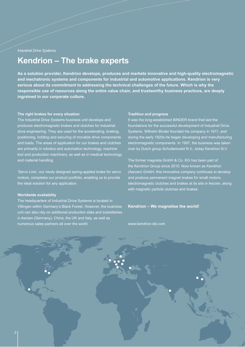
Worldwide availabilityThe headquarters of Industrial Drive Systems is located in Villingen within Germany’s Black Forest. However, the business unit can also rely on additional production sites and subsidiaries in Aerzen (Germany), China, the UK and Italy, as well as numerous sales partners all over the world.
Tradition and progressIt was the long-established BINDER brand that laid the foundations for the successful development of Industrial Drive Systems. Wilhelm Binder founded his company in 1911, and during the early 1920s he began developing and manufacturing electromagnetic components. In 1997, the business was taken over by Dutch group Schuttersveld N.V., today Kendrion N.V.
The former magneta GmbH & Co. KG has been part of the Kendrion Group since 2010. Now known as Kendrion (Aerzen) GmbH, this innovative company continues to develop and produce permanent magnet brakes for small motors, electromagnetic clutches and brakes at its site in Aerzen, along with magnetic particle clutches and brakes.
Kendrion – We magnetise the world!
www.kendrion-ids.com
Industrial Drive SystemsDie Welt von Kendrion Industrial Drive SystemsKendrion – The brake expertsAs a solution provider, Kendrion develops, produces and markets innovative and high-quality electromagnetic and mechatronic systems and components for industrial and automotive applications. Kendrion is very serious about its commitment to addressing the technical challenges of the future. Which is why the responsible use of resources along the entire value chain, and trustworthy business practices, are deeply ingrained in our corporate culture.
3
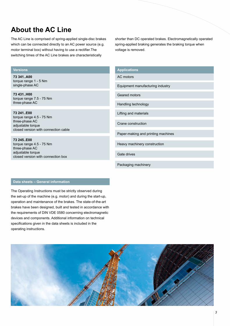
About the AC LineThe AC Line is comprised of spring-applied single-disc brakes which can be connected directly to an AC power source (e.g. motor terminal box) without having to use a rectifier.The switching times of the AC Line brakes are characteristically
shorter than DC operated brakes. Electromagnetically operated spring-applied braking generates the braking torque when voltage is removed.
The Operating Instructions must be strictly observed during the set-up of the machine (e.g. motor) and during the start-up, operation and maintenance of the brakes. The state-of-the-art brakes have been designed, built and tested in accordance with the requirements of DIN VDE 0580 concerning electromagnetic devices and components. Additional information on technical specifications given in the data sheets is included in the operating instructions.
Data sheets – General information
Versions
73 341..A00torque range 1 - 5 Nmsingle-phase AC
73 431..H00torque range 7.5 - 75 Nmthree-phase AC
73 241..E00torque range 4.5 - 75 Nmthree-phase ACadjustable torqueclosed version with connection cable
73 245..E00torque range 4.5 - 75 Nmthree-phase ACadjustable torqueclosed version with connection box
Applications
AC motors
Equipment manufacturing industry
Geared motors
Handling technology
Lifting and materials
Crane construction
Paper-making and printing machines
Heavy machinery construction
Gate drives
Packaging machinery
4
AC Line
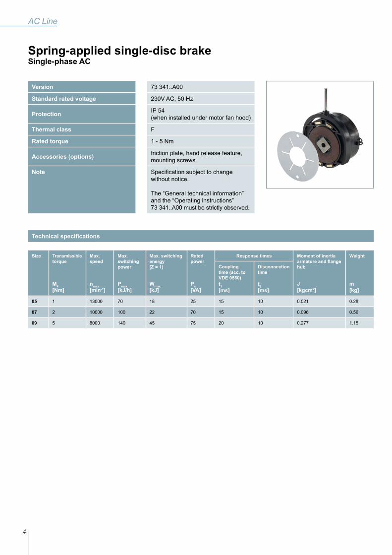
Version 73 341..A00
Standard rated voltage 230V AC, 50 Hz
Protection IP 54 (when installed under motor fan hood)
Thermal class F
Rated torque 1 - 5 Nm
Accessories (options) friction plate, hand release feature, mounting screws
Note Specification subject to change without notice.
The “General technical information” and the “Operating instructions” 73 341..A00 must be strictly observed.
Spring-applied single-disc brakeSingle-phase AC
Technical specifications
Size Transmissible torque
M4[Nm]
Max. speed
nmax[min-1]
Max. switching power
Pmax[kJ/h]
Max. switching energy(Z = 1)
Wmax[kJ]
Rated power
Ps[VA]
Response times Moment of inertia armature and flange hub
J[kgcm2]
Weight
m[kg]
Couplingtime (acc. to VDE 0580)t1[ms]
Disconnection time
t2[ms]
05 1 13000 70 18 25 15 10 0.021 0.28
07 2 10000 100 22 70 15 10 0.096 0.56
09 5 8000 140 45 75 20 10 0.277 1.15

5
Size d d1 d2 d3 d4(H7) d5 d6 b b1 b2 b3
05 56 12 46 22 81)/112) – 2.84) 32 30.5 – –
07 71 15 60 28 101)/142) 4 3.84) 39 37.5 5 76
09 90 16 75 32 131)/152) 4 5.84) 47.5 46 6 96
1) Min. bore2) Max. bore2) Shaft ISO fitting k6 (1),2))
3) Max. air gap up to friction disc replacement4) Pre-bored in case of hubs with finished bore d4
Dimensions [mm]
Size h h1 L L1 L2 L3 s smax3) M F [N] α
05 – – 5 0.5 400 6 0.2 0.6 2 x M3 – –
07 48 81 7 0.5 400 6 0.2 0.6 2 x M4 ca. 26 ca. 6°
09 59 92 8 0.5 400 6 0.2 0.6 2 x M5 ca. 42 ca. 6°
Size Friction plate Hand releasefeature
Mounting screws
with corrosionprotection
without corrosionprotection
Screw Rated torque Material number Screws per brake
05 73 34105A02902 73 34105A00902 – ISO 1207 - M3 x 35 - 4.8 1 Nm 302 074 2
07 73 34107A02902 73 34107A00902 73 34107A00940 ISO 1207 - M4 x 45- 4.8 2.5 Nm 302 165 2
09 73 34109A02902 73 34109A00902 73 34109A00940 ISO 1207 - M5 x 55- 4.8 5 Nm 302 252 2
Accessories
release force F
turned
air gapflying leads 2x0.62mm2
transport fixture(to be removed after
brake installation)
6
AC Line
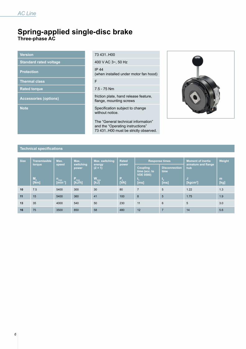
Version 73 431..H00
Standard rated voltage 400 V AC 3~, 50 Hz
Protection IP 44 (when installed under motor fan hood)
Thermal class F
Rated torque 7.5 - 75 Nm
Accessories (options) friction plate, hand release feature, flange, mounting screws
Note Specification subject to change without notice.
The “General technical information” and the “Operating instructions” 73 431..H00 must be strictly observed.
Spring-applied single-disc brakeThree-phase AC
Technical specifications
Size Transmissible torque
M4[Nm]
Max. speed
nmax[min-1]
Max. switching power
Pmax[kJ/h]
Max. switching energy(Z = 1)
Wmax[kJ]
Rated power
Ps[VA]
Response times Moment of inertia armature and flange hub
J[kgcm2]
Weight
m[kg]
Couplingtime (acc. to VDE 0580)t1[ms]
Disconnection time
t2[ms]
10 7.5 5400 300 30 80 7 5 1.22 1.3
11 15 5400 360 41 100 8 5 1.75 1.9
13 35 4000 540 50 230 11 6 5 3.0
16 75 3500 850 58 480 12 7 14 5.6
7
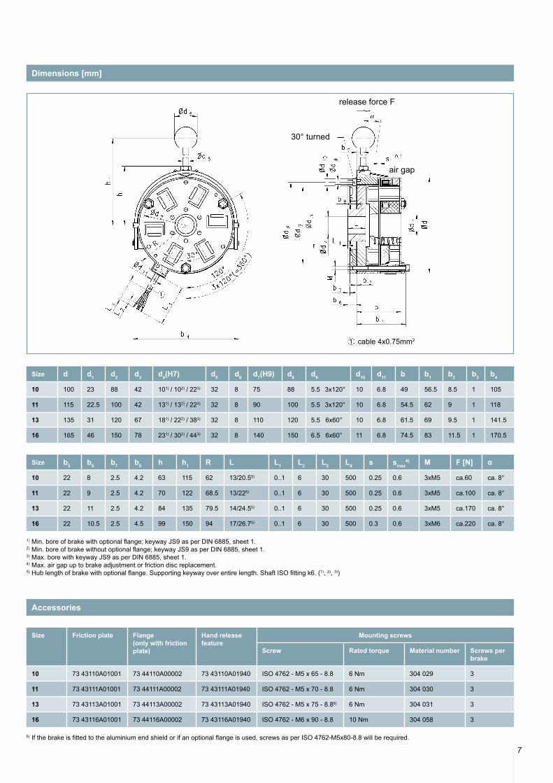
Size d d1 d2 d3 d4(H7) d5 d6 d7(H9) d8 d9 d10 d11 b b1 b2 b3 b4
10 100 23 88 42 101) / 102) / 223) 32 8 75 88 5.5 3x120° 10 6.8 49 56.5 8.5 1 105
11 115 22.5 100 42 131) / 132) / 223) 32 8 90 100 5.5 3x120° 10 6.8 54.5 62 9 1 118
13 135 31 120 67 181) / 222) / 383) 32 8 110 120 5.5 6x60° 10 6.8 61.5 69 9.5 1 141.5
16 165 46 150 78 231) / 302) / 443) 32 8 140 150 6.5 6x60° 11 6.8 74.5 83 11.5 1 170.5
Size b5 b6 b7 b8 h h1 R L L1 L2 L3 L4 s smax4) M F [N] α
10 22 8 2.5 4.2 63 115 62 13/20.55) 0..1 6 30 500 0.25 0.6 3xM5 ca.60 ca. 8°
11 22 9 2.5 4.2 70 122 68.5 13/225) 0..1 6 30 500 0.25 0.6 3xM5 ca.100 ca. 8°
13 22 11 2.5 4.2 84 135 79.5 14/24.55) 0..1 6 30 500 0.25 0.6 3xM5 ca.170 ca. 8°
16 22 10.5 2.5 4.5 99 150 94 17/26.75) 0..1 6 30 500 0.3 0.6 3xM6 ca.220 ca. 8°
1) Min. bore of brake with optional flange; keyway JS9 as per DIN 6885, sheet 1.2) Min. bore of brake without optional flange; keyway JS9 as per DIN 6885, sheet 1.3) Max. bore with keyway JS9 as per DIN 6885, sheet 1.4) Max. air gap up to brake adjustment or friction disc replacement. 5) Hub length of brake with optional flange. Supporting keyway over entire length. Shaft ISO fitting k6. (1), 2), 3))
Dimensions [mm]
Size Friction plate Flange(only with frictionplate)
Hand release feature
Mounting screws
Screw Rated torque Material number Screws per brake
10 73 43110A01001 73 44110A00002 73 43110A01940 ISO 4762 - M5 x 65 - 8.8 6 Nm 304 029 3
11 73 43111A01001 73 44111A00002 73 43111A01940 ISO 4762 - M5 x 70 - 8.8 6 Nm 304 030 3
13 73 43113A01001 73 44113A00002 73 43113A01940 ISO 4762 - M5 x 75 - 8.86) 6 Nm 304 031 3
16 73 43116A01001 73 44116A00002 73 43116A01940 ISO 4762 - M6 x 90 - 8.8 10 Nm 304 058 3
Accessories
6) If the brake is fitted to the aluminium end shield or if an optional flange is used, screws as per ISO 4762-M5x80-8.8 will be required.
release force F
cable 4x0.75mm2
30° turned
air gap

8
AC Line
Version 73 241..E00 – closed version with connection cable
73 245..E00 – closed version with connection box
Standard rated voltage 400 V AC 3~, 50 Hz
Protection IP 65 (when installed under motor fan hood)
Thermal class F
Rated torque 4.5 - 75 Nm
Accessories (options) hand release feature, mounting screws
Note Specification subject to change without notice.
The “General technical information” and the “Operating instructions” 73 241..E00 or 73 245..E00 must be strictly observed.
Spring-applied single-disc brakeThree-phase AC
Technical specifications
Size Trans-missible torque
M4[Nm]
Max. reachablerated torque with fully screwed inadjustment ring
M2 max[Nm]
Max. speed
nmax[min-1]
Max. switching power
Pmax[kJ/h]
Max. switching energy(Z = 1)
Wmax[kJ]
Rated power
Ps[VA]
Response times Moment of inertia armature and flange hub
J[kgcm2]
Weight
m[kg]
Couplingtime (acc. to VDE 0580)t1[ms]
Disconnection time
t2[ms]
10 4.5-7.5 8 5400 450 60 80 7 5 1.22 1.7
11 9-15 16.5 5000 500 65 100 8 5 1.75 2.5
13 21-35 38.5 4000 680 72 230 11 6 5 3.8
16 45-75 82.5 3500 850 82 480 12 7 14 7.5
9
Size d d1 d2 d3 d4(H7) d5 d6 d7(H9) d8 d9 d10 d11 b b1 b2 b3 b4
10 110 0...23 88 48.9 101) / 222) 32 8 75 100 40 5.5 4.1 62.5 59.5 2 50 67
11 128 0...22.5 100 48.9 121) / 222) 32 8 90 115 40 5.5 4.1 72 66 2 50 67
13 148 0...31 120 76 171) / 382) 32 8 110 135 50 5.5 5.1 80.5 74.5 2 50 67
16 176 0...46 150 88 231) / 452) 32 8 140 165 60 6.5 7.1 93.1 86.1 2 50 67
Size b5 h h1 h2 R L L1 L2 s smax3) M F [N]4) α ß
10 2.5 66 122 86 64 20.5 0.5 500 0.2 0.6 3xM5 20 ca. 26° 3x120°
11 2.5 78 135 94 71 20.5 0.5 500 0.2 0.6 3xM5 40 ca. 26° 3x120°
13 2.5 91 148 105 83 24 0.5 500 0.2 0.6 6xM5 80 ca. 26° 6x60°
16 2.5 109.5 168 121 100 26.5 0.5 500 0.2 0.6 6xM6 100 ca. 26° 6x60°
1) Min. bore with keyway JS9 as per DIN 6885, sheet 12) Max. bore with keyway JS9 as per DIN 6885, sheet 1; supporting keyway entire length. Shaft ISO fitting k6 (1),2))3) Max. air gap referred to max. rated torque (standard)4) Release force F (approx.) referred to max. rated torque (standard)
Dimensions [mm]
Size Hand release feature Mounting screws
Screw Rated torque Material number Screws per brake
10 73 24110A00940 ISO 4762 - M5 x 70 - 8.8 6 Nm 304 03 3
11 73 24111A00940 ISO 4762 - M5 x 75 - 8.8 6 Nm 304 031 3
13 73 24113A00940 ISO 4762 - M5 x 85 - 8.8 6 Nm 304 035 6
16 73 24116A00940 ISO 4762 - M6 x 100 - 8.8 10 Nm 304 060 6
Accessories
release force F
air gap
type 73 241..E00with connection cable
type 73 245..E00
cable 4x0.75mm2

Kendrion (Villingen) GmbHWilhelm-Binder-Strasse 4-678048 Villingen-SchwenningenGermanyTel: +49 7721 877-0Fax: +49 7721 [email protected]
© KENDRION 24.10.2016