ac drive cable selection pdf from i&s 1263400720
TRANSCRIPT
December 2009 ✦ 49
Manufacturers of medium and large AC drives typi-cally provide information on the requirements for
power cables connecting the inverter to the AC motor and from the drive isolation transformer to the con-verter. Cable and panel grounding recommendations are also included. Cable supplier catalogs and Web sites provide detailed information, but not necessar-ily everything needed to determine if the AC drive manufacturer’s recommendations are being met. This paper provides typical requirements, reasons for those requirements, and some useful insights to help the reader bridge the gap between drive supplier require-ments and cable supplier published data.
BackgroundThe availability of cost-effective thyristor- and transis-tor-based power devices made Pulse Width Modulated (PWM) power conversion practical.1 As is the case with most advances in technology, issues not seen in previ-ous generations of drives came to light. These included motor insulation problems, bearing failures, interfer-ence with or destruction of existing drive systems, and interference with unrelated plant equipment. Most, if not all, of these phenomena are attributable to switch-ing speeds on the order of 10–100 times faster than the thyristors used in conventional DC power conversion.
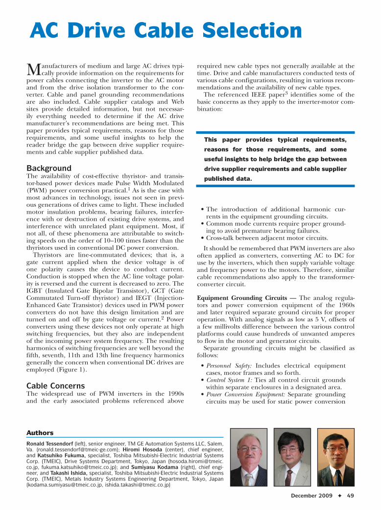
Thyristors are line-commutated devices; that is, a gate current applied when the device voltage is of one polarity causes the device to conduct current. Conduction is stopped when the AC line voltage polar-ity is reversed and the current is decreased to zero. The IGBT (Insulated Gate Bipolar Transistor), GCT (Gate Commutated Turn-off thyristor) and IEGT (Injection-Enhanced Gate Transistor) devices used in PWM power converters do not have this design limitation and are turned on and off by gate voltage or current.2 Power converters using these devices not only operate at high switching frequencies, but they also are independent of the incoming power system frequency. The resulting harmonics of switching frequencies are well beyond the fifth, seventh, 11th and 13th line frequency harmonics generally the concern when conventional DC drives are employed (Figure 1).
Cable Concerns The widespread use of PWM inverters in the 1990s and the early associated problems referenced above
required new cable types not generally available at the time. Drive and cable manufacturers conducted tests of various cable configurations, resulting in various recom-mendations and the availability of new cable types.
The referenced IEEE paper3 identifies some of the basic concerns as they apply to the inverter-motor com-bination:
• The introduction of additional harmonic cur-rents in the equipment grounding circuits.
• Common mode currents require proper ground-ing to avoid premature bearing failures.
• Cross-talk between adjacent motor circuits.
It should be remembered that PWM inverters are also often applied as converters, converting AC to DC for use by the inverters, which then supply variable voltage and frequency power to the motors. Therefore, similar cable recommendations also apply to the transformer-converter circuit.
Equipment Grounding Circuits — The analog regula-tors and power conversion equipment of the 1960s and later required separate ground circuits for proper operation. With analog signals as low as 5 V, offsets of a few millivolts difference between the various control platforms could cause hundreds of unwanted amperes to flow in the motor and generator circuits.
Separate grounding circuits might be classified as follows:
• Personnel Safety: Includes electrical equipment cases, motor frames and so forth.
• Control System 1: Ties all control circuit grounds within separate enclosures in a designated area.
• Power Conversion Equipment: Separate grounding circuits may be used for static power conversion
AC Drive Cable Selection
This paper provides typical requirements,
reasons for those requirements, and some
useful insights to help bridge the gap between
drive supplier requirements and cable supplier
published data.
Authors
Ronald Tessendorf (left), senior engineer, TM GE Automation Systems LLC, Salem, Va. ([email protected]); Hiromi Hosoda (center), chief engineer, and Katsuhiko Fukuma, specialist, Toshiba Mitsubishi-Electric Industrial Systems Corp. (TMEIC), Drive Systems Department, Tokyo, Japan ([email protected], [email protected]); and Sumiyasu Kodama (right), chief engi-neer, and Takashi Ishida, specialist, Toshiba Mitsubishi-Electric Industrial Systems Corp. (TMEIC), Metals Industry Systems Engineering Department, Tokyo, Japan ([email protected], [email protected])
50 ✦ Iron & Steel Technology
equipment, depending on local codes and manu-facturer. This may be tied to the Personnel Safety ground but not the Control System ground.
• Control System 2: Multiple control grounding cir-cuits may exist, especially as additional lines are added to existing facilities.
Control of Common Mode Currents — A simplistic view of common mode is that any difference in poten-tial between two points will cause a current to flow
through the path of least resistance. Since the potential difference can consist of many different frequencies, the mathematical solution can be extremely complex. The basic solution is to ensure that all potentials are equidistant to ground, with the path of least resistance determined by the installation to not be through equip-ment components that can fail due to unwanted ground currents.
The primary concern here is that improper installa-tion can introduce the motor terminals to much higher
voltages than the insulation is design to accom-modate. In addition, the path of least resistance to common mode current may well be the motor bearing, which generally shortens bear-ing life. In cases where both motor bearings are insulated, the path of least resistance may be passed to the driven equipment bearing. Note that sensors attached to the motor shaft, such as tachometers, must be properly protected to avoid their bearings becoming the path of least resistance.
A related cause of high voltage at the motor terminals is the standing wave concept. The combination of high device switching speeds and PWM control that allows a high-frequency string of voltage pulses being sent from the inverter can cause motor voltages many times nominal. For a particular cable type, there is some cable length that maximizes this voltage component. The PWM control algorithm can mitigate this issue.
Figure 1
Typical harmonic spectrum of PWM drive.
Figure 2
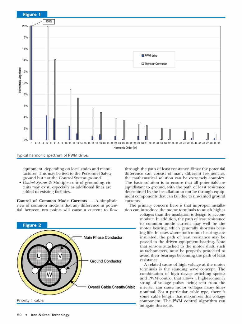
Priority 1 cable.

December 2009 ✦ 51
Circuit Cross-Talk — Physical separation of power cables and control cables is gener-ally recommended by drive manufacturers and may also be required by personnel safety codes. Multiple inverter-motor cables in the same raceway for long distances can have elec-tromagnetic and/or electrostatic coupling. This could result in one system interfering with another’s operation. Personnel safety is another concern, in that an individual may be doing maintenance on an un-energized power circuit that has voltage/current induced from an operating drive.
Electromagnetic coupling from power cables can also interfere with other equipment, such as radios, control circuits and instrumentation.
Thyristor and Diode Converters Power cables between drive isolation transform-ers and thyristor or diode converters follow the same guidelines used for DC drives. Special cable is not required.
PWM Converters and Inverters As noted previously, PWM AC-DC converters and DC-AC inverters operate at high switching frequencies, producing harmonics well beyond the fifth, seventh, 11th and 13th associated with thyristor and diode AC-DC converters. The basic requirements for properly installed power cabling that minimizes the undesirable effects include:
• Three symmetrically arranged phase con-ductors.
• Three symmetrically arranged ground con-ductors.
• High-integrity overall cable sheath. • Individual phase conductor shields when
RMS voltages above 2,400 VAC are recom-mended.
The following cable configurations are priori-tized from 1 to 4, or best practice to less desir-able alternatives.
Priority 1 Cable — The arrangement shown in Figure 2, when properly terminated, meets the above criteria. The cable does not introduce phase unbalance and minimizes high-frequency emissions. This cable type is designated Priority 1 because it results in the minimum common mode currents in the grounding circuit and minimum interference with other equipment in the facility.
Overall cable sheaths or shields may be implemented using several methods. These include:
• Continuous, welded corrugated aluminum sheath. Generally considered the best tech-nical solution for grounding high-frequen-cy emissions, it also provides very good
Figure 3
Priority 2 cable.
Figure 4
Priority 3 cable.
Figure 5
Priority 4 cable.
52 ✦ Iron & Steel Technology
mechanical protection and is sometimes referred to as “armored.” This type is also the most expen-sive and difficult to install due to the rigidity of the sheath.
• Corrugated and longitudinally applied sheath with overlap. The material is usually copper and provides a good grounding path. The corrugated sheath flattens when the cable is bent, providing an unbroken sheath.
• Circumferentially wrapped flat copper tape with 133–150% overlap. The level of overlap ensures coverage if the bend radius is not too severe. Separation or gaps in the sheath allow some level of unwanted emissions.
• Weaved sheaths are found on some cables adver-tised as VFD. Weaves do not provide a 100% emis-sion shield due to gaps in the weave.
Priority 2 Cable — Priority 2 cable has a single, centrally placed ground conductor. Although shown for com-pleteness and technically a solution, it has proved dif-ficult to confirm that the ground conductor is centrally placed. It seems to be more common for the ground conductor to be just one of four randomly placed cables in the bundle and not centered as shown in Figure 3. Unsymmetrical cable should be avoided.
Priority 3 Cable — Priority 3 cable (Figure 4) has no separate ground conductor and relies solely on the over-all cable sheath for grounding and emission control.
Priority 4 Cable — Priority 4 cables (Figure 5) have three individual cables symmetrically placed. In all arrange-ments, symmetrical main phase conductors are required to keep the phase currents balanced, with the goal of
Figure 6
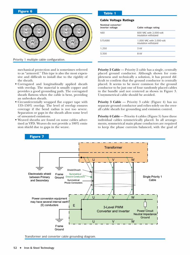
Priority 1 multiple cable configuration.
Cable Voltage Ratings
Nominal converter/ inverter voltage Cable voltage rating
460 600 VAC with 2,000-volt insulation withstand
575/690 1,000 VAC with 2,000-volt insulation withstand
1,250 3 kV
3,300 8 kV
Table 1
Figure 7
Transformer and converter cable grounding diagram.
December 2009 ✦ 53
minimizing common mode ground currents and high-frequency emissions. Some manufacturers allow the use of Priority 4 cables when Priority 1–3 cables are not avail-able. Special care should be taken to ensure symmetrical placement of the three single-phase cables.
In the event Priority 4 cable is used, a separate ground conductor should be run in a separate path (conduit) to avoid the Priority 2 case of unbalanced electromagnetic effects. There will be phase unbalance with Priority 4 cables regardless of the care taken during installation. Also note that since there is no overall three-phase sheath, all three individual cable sheaths should be grounded per the manufacturer’s recommendation.
Multiple Cables When multiple cables are required for ampacity pur-poses, each cable should contain all three phases, as shown in Figure 6 for Priority 1 cables. Cables are
routed through buried conduits or placed in cable trays, or both. The ampacity de-rating rules recommended by the cable manufacturer should be observed.
Should it be necessary to use multiple single-phase cables, there are two possibilities. The Priority 4 case can be followed, or the cable runs are placed in indi-vidual phase conduits to minimize common mode cur-rents. However, this second case requires point-to-point buried conduit with no proximity to other power or control cables. In the case where cables are randomly run without regard to phase, cable sheath terminations may burn off due to excessive currents. In this case, the voltage driving the current is relatively high and may be considered a personnel hazard.
Cable Voltage Rating All cables must meet local codes and be rated for the RMS circuit voltage in which they are installed. Some
Power CircuitNeutral Impedance
Ground
3-Level PWMConverter and Inverter
WVU
WVU
Disconnect(if included)
WVU
WVU
Motor
WVU
E
Power conversion equipmentmay have several internal earth
(E) conductors
FrameGround
FrameGround
FrameGround
A separate ground conductor isrecommended when Priority 4
single phase cable is used
Individual Priority4 cables, two (2)
per phase shown
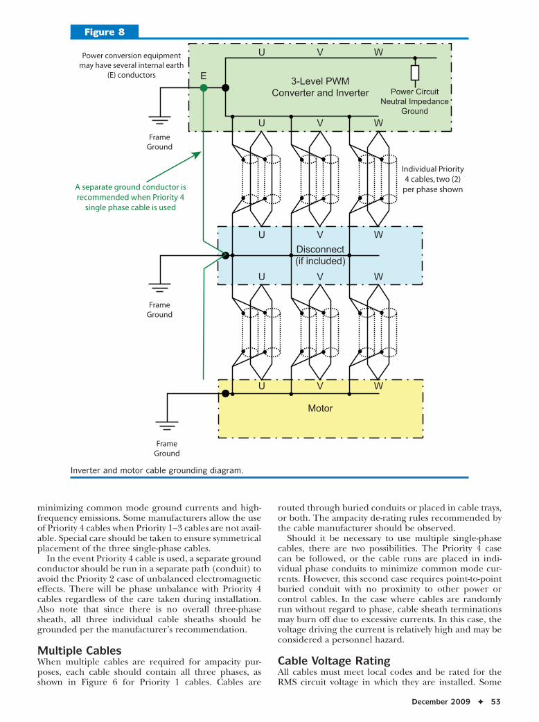
Figure 8
Inverter and motor cable grounding diagram.
54 ✦ Iron & Steel Technology
suggested cable ratings available in North America are given in Table 1.
Cable Grounding Always refer to the equipment manufacturer’s documen-tation for proper handling and installation, including grounding. Figure 7 illustrates the grounding method for the case of a PWM converter connection to a trans-former with a single Priority 1 cable.
Note that the cable sheath/shield is grounded at both ends of the cable. The three symmetrical ground conductors are also grounded at each end of the cable. Drive isolation transformers are generally provided with an electrostatic shield between the primary and secondary windings which is connected to the system
grounding circuit. The cable sheath/shield and ground conductors are also connected to the system grounding circuit.
Converters are generally provided with an internal ground (earth) bus for cable grounding purposes, and perhaps a separate control ground bus. As noted earlier, separate external ground buses for control and power are not generally used in new installations. Therefore, all grounds eventually terminate to the same system grounding circuit, designated “frame ground” in Figure 7.
In Figure 8, the inverter connection to the motor uses Priority 4 cables and includes a motor disconnect. This case requires careful grounding of the individual shields/sheaths, plus the separately run ground cable to mediate the common mode ground currents that this installation will incur. All cables used have the
Parameters for Model Simulation
DC bus voltage 2,345 VDC
Dv/dt of switching 2,345 V/microsecond
Motor load No load, no current
Cable length 90 m
Cable parallel number 2 parallel
Cable layout Priority 4 (Figure 11)
Cable model EMTDC cable (Figure 12)
Table 2
Figure 10
Measured ground currents.
Inverter
Neutral Point
2345VQ1
Q2
Q3Q4
Stray C2345VNeutral point
Ground Resistor2.5 ohm
len E2 Neutral Point Earth
E1 Earth
E2 EarthTerminal Box
E1 EarthTerminal Box
E2 EarthPole
E1 EarthPoleIE2
Earth
PipeFrame Earth
Channel Base
lie
U
V
W
SE point
Cable
Stray C
Earth
Installing earth
Motor
Stray C
lem
lem2
Earth via Building
Figure 9
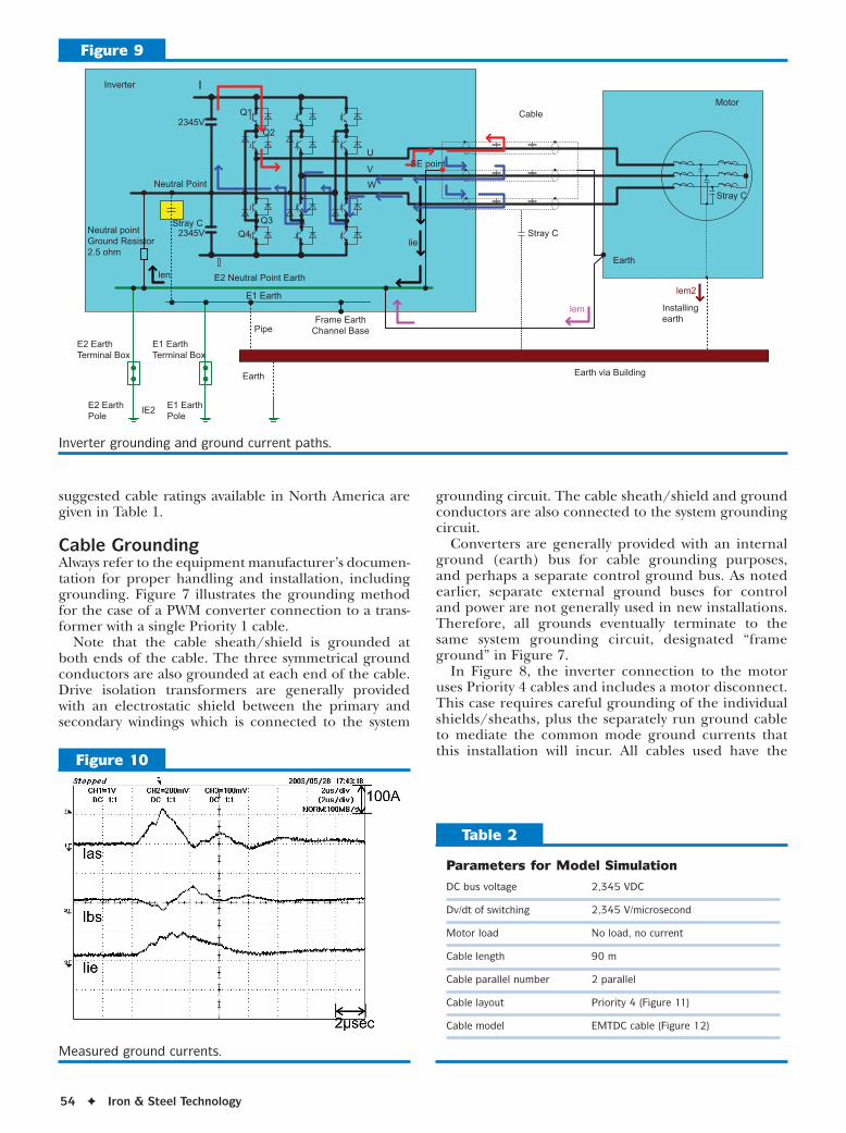
Inverter grounding and ground current paths.
December 2009 ✦ 55
shield/sheath grounded at both ends. Again, please consult the manufacturer’s documentation to confirm their recommendations.
Note that Figure 8 does not attempt to illustrate the cable physical arrangement. Priority 4 guidelines are implied and should be followed.
Case Study of Individual Cables Figure 9 shows the main power and grounding cir-cuits of a medium-voltage IEGT main drive applied in a rolling mill. The main power cables between the inverter and motor are Priority 4 type; that is, three individually shielded cables. Each cable has a sheath used as a shield and grounded at both ends. There are multiple paths for ground currents to flow, including the intend-ed ground wires and stray capacitance. The ground current flows as follows:
• As an initial condition, all of the inverter output voltages are zero.
• The U-phase power devices Q1 and Q2 are turned on, applying +2,345 V to the U-phase output.
• Ground current flows as indicated by the arrows in Figure 9.
When the motor load current is zero, the U-phase current flows from the U-phase cable through the sheath and returns to the inverter SE point. The current return to the inverter main power circuit is mainly through two paths. One path is the neutral ground-ing point, and the other through the V-phase and W-phase sheaths and cables.
Figure 10 shows the ground currents Ias, Ibs and Iie as measured in the actual installation. The Ias peak cur-rent is 120 A with a frequency of more than 100 Hz.
Simulation — A simulation was run using PSCAD/EMTDC version 3.0.8 to confirm the model against the field measurements. The parameters are shown in Table 2.
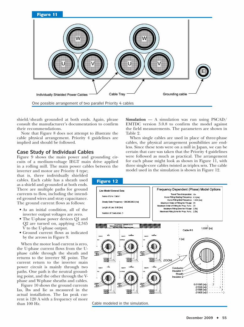
When single cables are used in place of three-phase cables, the physical arrangement possibilities are end-less. Since these tests were on a mill in Japan, we can be certain that care was taken that the Priority 4 guidelines were followed as much as practical. The arrangement for each phase might look as shown in Figure 11, with three single-core cables twisted as triplex sets. The cable model used in the simulation is shown in Figure 12.
Figure 11
One possible arrangement of two parallel Priority 4 cables
Figure 12
Cable modeled in the simulation.

56 ✦ Iron & Steel Technology
The simulation results are shown in Figure 13. The simulated ground currents Ias, Ibs and Iie are similar to the measured values of Figure 8, verifying the simula-tion results.
The ground currents Iem, Iem2 and Ien of Figure 9 were also simulated. The impedance to earth of the motor side currents, Iem and Iem2, is higher than the impedance to ground of the neutral point established in the inverter, and little or no current is observed. The ground path of the Ien and Iie currents are nearly the same, and so the simulated ground currents are practically the same. The intention of the neutral point grounding resistor is to control the ground current, so the simulation confirms the desired result. Keeping the unwanted currents within the inverter and cable sheaths mitigates the amount of unwanted electri-cal noise introduced into the plant ground grid. It is important to note that the cable sheath can carry sig-nificant repetitive pulse-shaped currents and must be rated and properly terminated to carry these currents.
Conclusions Differences in PWM drive designs may result in differ-ent cable recommendations between manufacturers. In some countries, the recommended cables may not be available. However, the manufacturer’s recommenda-tions should be followed as closely as possible. Proper cabling installation of high-performance PWM drives will avoid interference with the operation of other plant equipment, as well as ensure proper operation and life of the connected equipment.
References1. R.I. Tessendorf and H. Hosoda, “AC Drive Technology 5-Year
Trends,” AISTech 2004 Conference Proceedings.2. R.I. Tessendorf, “PWM Drives,” AISE AC Drives Seminar,
1999.3. J.M. Bentley and P.J. Link, “Evaluation of Motor Power Cables
for PWM AC Drives,” IEEE Transactions on Industry Applications, Vol. 33, No. 2, March/April 1997.
4. JEMA (The Japan Electrical Manufacturer’s Association), “Investigation Report of Power Cables for Medium Voltage Inverters,” 2005. ✦
Did you find this article to be of significant relevance to the advancement of steel technology? If so, please consider nominating it for the AIST Hunt-Kelly Outstanding Paper Award at www.aist.org/huntkelly.
This paper was presented at AISTech 2009 — The Iron & Steel Technology Conference and Exposition, St. Louis, Mo., and published in the Conference Proceedings.
Figure 13
Results of the ground current simulation: (left) inverter ground currents and (right) other ground currents.