ac charging connector of type 1 (t1v-02) -...
TRANSCRIPT
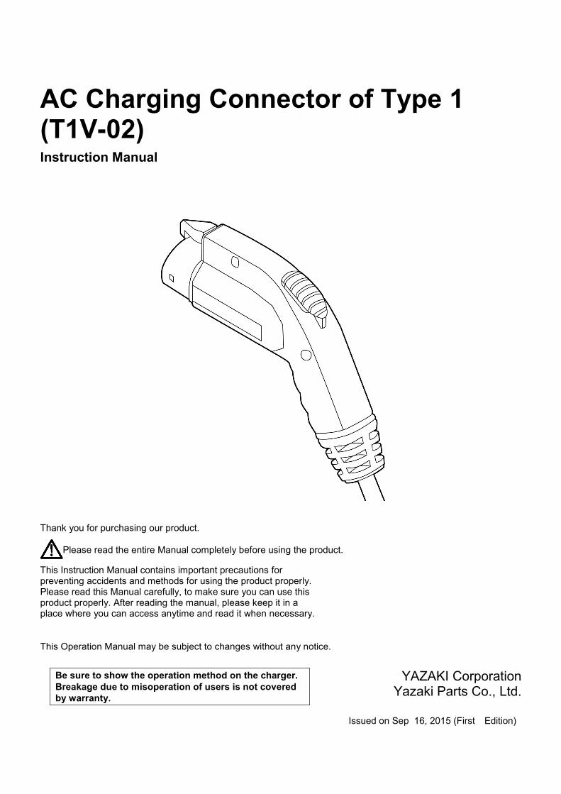
AC Charging Connector of Type 1 (T1V-02) Instruction Manual
Thank you for purchasing our product.
Please read the entire Manual completely before using the product.
This Instruction Manual contains important precautions for preventing accidents and methods for using the product properly. Please read this Manual carefully, to make sure you can use this product properly. After reading the manual, please keep it in a place where you can access anytime and read it when necessary.
This Operation Manual may be subject to changes without any notice.
YAZAKI Corporation
Yazaki Parts Co., Ltd. Issued on Sep 16, 2015 (First Edition)
Be sure to show the operation method on the charger. Breakage due to misoperation of users is not covered by warranty.

2 Table of contents
* This product is dedicated to the AC charging system of Type 1. Please do not use it for other charging systems.
• Is compliant with Appendices 4-1 and 6 to Article 1 of Ministerial Ordinance for Technical Standards of Electrical Appliances.
• Compliance with APPENDIX A to SAE J1772 Oct (2012).
• Compliance with IEC 62196-1 2011-10 (Product is capped).
• Compliance with IEC 62196-2 2011-10 (Product is capped).
Table of contents
Names and functions of parts ................................................................. 3
Safety precautions ................................................................................... 5
How to use the product ......................................................................... 10 Connecting charging connector .......................................................... 10 Removing the charging connector ...................................................... 11 When stopping charging in the middle ............................................... 12
Maintenance ........................................................................................... 13 Daily inspection and maintenance ...................................................... 13 Regular checks ................................................................................... 16
When you have a problem ..................................................................... 17
Specifications ......................................................................................... 19 Japanese specifications (Rated current of 20 A) ................................ 19 Japanese and European specifications (Rated current of 20A) ......... 20 North American specifications (Rated current of 20A) ........................ 21 North American specifications (Rated current of 30 A) ....................... 22
Warranty [AC Charging Connector of TYPE 1 (T1V-02)] ..................... 23

Names and functions of parts 3
Names and functions of parts
Product name: AC charging connector of Type 1 (T1V-02)
(Hereinafter referred to as “charging connector”)
① Latch Hook that fixes (locks) the coupling with the vehicle inlet.
② Grip Portion at which a user grips the charging connector.
③ Housing Portion inserted into the vehicle inlet.
④ Guide (convex) Projection in the lower part of the housing. The housing can be connected properly by inserting it such that the projections are aligned with the grooves (concave) in the vehicle inlet.
⑤ Terminal Metal part within the housing. Connected with the vehicle inlet to pass electricity.
⑥ Cap Lid to prevent the ingress of foreign substances. (It may not be provided, depending on the specifications.)
⑥
①
③
④
②
⑤
⑤

4 Names and functions of parts
⑦ Release button Button to uncouple the connector from the vehicle inlet at the end of charging.
⑧ Cable A bundle of wires for running electricity from power supply to a vehicle.
⑨ Vehicle inlet It is an insertion port on the side of vehicle
⑨
⑧
⑦

Safety precautions 5
Safety precautions
Please make sure to read through the “Safety precautions” before using the product. The “Safety precautions” contains important information for preventing damage to users, other persons and their property and using the charging connector safely.
■ Indication of symbols This manual indicates the level of risk or damage that may be caused by mishandling of the product with the following symbols: Please make sure to understand the content and follow the instructions contained herein.
Warning Indicates mishandling may result in death or serious injury.
Caution Indicates mishandling may result in injury or damage to property.
Each precaution has a corresponding symbol of “Caution”, “Prohibited” or “Must”.
Symbol calling for attention
Symbol indicating prohibited action
Symbol indicating “MUST”
* If your product malfunctions or is broken and can be no longer used, contact your distributor.
Caution
Prohibited No fire
Do not disassemble
Do not touch MUST

6 Safety precautions
Warning Failing to observe the following rules may result in death or serious injury due to fire or electric shock.
Do not disassemble, repair or modify. Doing so may cause fire, electric shock or injury.
Do not use the product at a higher voltage or current than the rating. Doing so may cause fire or electric shock. Be sure to confirm ratings set forth in the product manual.
Do not damage the cable or do not use the product with a damaged cable. Damaged cable may have the broken surface, which in turn causes wire breakage, fire or electric shock. In particular, do not use the cable while it is twisted. Doing so repeatedly is likely to damage or break the cable. • Do not allow the cable to be caught by a vehicle door, vehicle charging station, or outer wall.
• Do not run over the cable with tires or do not put a heavy object on it.
• Do not slam or rub the cable against the ground.
• Do not pull, twist or bend the cable by force.
• Do not approach the cable to a heating apparatus or do not heat it. Before and after using the charging connector, restore a damaged or twisted cable to the normal state. To use it safely, refer to the maintenance section (pages 13 to 16) of this document.
When you feel something unusual, stop charging. Doing so may result in fire or electric shock. When you have heard an unusual sound or felt an unusual smell, stop charging immediately. Do not use the product afterward.
Do not disassemble
Prohibited
Prohibited
MUST
Safety precautions 7
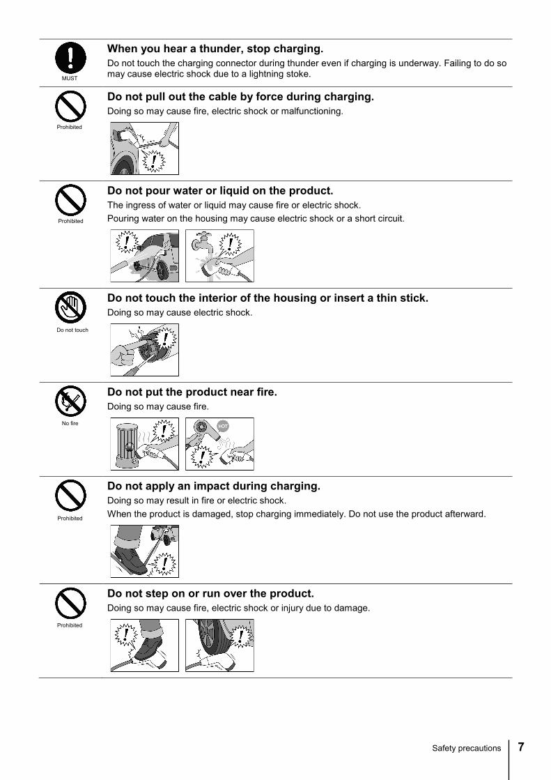
When you hear a thunder, stop charging. Do not touch the charging connector during thunder even if charging is underway. Failing to do so may cause electric shock due to a lightning stoke.
Do not pull out the cable by force during charging. Doing so may cause fire, electric shock or malfunctioning.
Do not pour water or liquid on the product. The ingress of water or liquid may cause fire or electric shock. Pouring water on the housing may cause electric shock or a short circuit.
Do not touch the interior of the housing or insert a thin stick. Doing so may cause electric shock.
Do not put the product near fire. Doing so may cause fire.
Do not apply an impact during charging. Doing so may result in fire or electric shock. When the product is damaged, stop charging immediately. Do not use the product afterward.
Do not step on or run over the product. Doing so may cause fire, electric shock or injury due to damage.
MUST
Prohibited
Prohibited
Do not touch
No fire
Prohibited
Prohibited

8 Safety precautions
Do not drop. Dropping the product or applying a strong impact to the product causes malfunctioning or breakage, which in turn result in fire, electric shock or injury. Should you drop it into a water pool, do not use it.
Do not step over, put something on or lean against the charging connector. Doing so may cause deformation or breakage, which may in turn result in fire, electric shock or injury.
Do not swing around or throw the charging connector. Doing so may break the charging connector, which may in turn result in injury.
Do not put a foreign substance inside the housing. Doing so may cause fire, electric shock or malfunctioning. Confirm that the housing contains no foreign substance before use. Remove the foreign substance in accordance with the maintenance section (pages 13 to 16).
Do not let children use the product alone or do not place it within their reach. Doing so may cause electric shock, injury or burn.
Do not join cables to increase their length. Doing so may cause electric leakage from a joint, which may in turn result in fire or electric shock. Use the product within the reach of the cable.
Do not drive the vehicle while the charging connector is left inserted. Doing so may cause an accident.
Power off the product during maintenance. Failing to do so may cause electric shock or injury.
Do not touch the terminal with a wet hand. Doing so may cause electric shock or injury.
Prohibited
Prohibited
Prohibited
Prohibited
Prohibited
Prohibited
Prohibited
MUST
Prohibited
Safety precautions 9
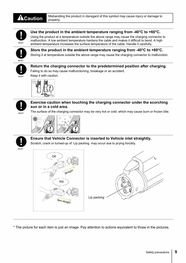
Caution Mishandling the product in disregard of this symbol may cause injury or damage to property.
* The picture for each item is just an image. Pay attention to actions equivalent to those in the pictures.
Use the product in the ambient temperature ranging from -40°C to +60°C. Using the product at a temperature outside the above range may cause the charging connector to malfunction. A low ambient temperature hardens the cable and makes it difficult to bend. A high ambient temperature increases the surface temperature of the cable. Handle it carefully.
Store the product in the ambient temperature ranging from -40°C to +80°C. Storing it at temperature outside the above range may cause the charging connector to malfunction.
Return the charging connector to the predetermined position after charging. Failing to do so may cause malfunctioning, breakage or an accident. Keep it with caution.
Exercise caution when touching the charging connector under the scorching sun or in a cold area. The surface of the charging connector may be very hot or cold, which may cause burn or frozen bite.
Ensure that Vehicle Connector is inserted to Vehicle inlet straightly. Scratch, crack or turned-up of Lip packing may occur due to prying forcibly.
MUST
MUST
MUST
MUST
MUST
OK
NG
Lip packing

10 How to use the product
How to use the product
Connecting charging connector
Park your vehicle at a position closer to a charging connector or a charging station such that the cable is not tensioned.
1. Confirm that the housing and the vehicle inlet contain no foreign substance.
If either of them contains a foreign substance, remove it in accordance with the maintenance section (pages 13 to 16).
2. Hold the charging connector with hands, align the guides (convex) with the grooves (concave) in the vehicle inlet and insert the connector straight.
Do not press and hold the Release button during insertion. Doing so makes no clicking sound when the housing is locked in place. You cannot determined whether it is locked properly or not.
When it is connected properly, a clicking sound is heard. The vehicle is ready for being charged.
When you cannot insert it properly, pull out the housing while pressing and holding the Release button. Confirm that the housing or the vehicle inlet contains no foreign substance and then insert it again.
Do not press the Release button while the housing is connected properly.
Note
Note
Memo
Note
Do not press and hold the button.
Vehicle inlet
Press it forward until it clicks into place.
Align the convex with the concave.

How to use the product 11
Pulled out straight
Removing the charging connector When charging is completed, remove the charging connector.
1. Hold the grip and pull out the charging connector straight while pressing and holding the Release button.
Pressing the Release button stops charging and allows you to pull out the charging connector.
Do not pull out the charging connector without pressing the Release button. In particular, do not pull the cable to pull out the charging connector. Exercise caution not to drop the charging connector.
2. Return the charging connector to the predetermined position. Be sure to return to the predetermined position carefully.
Exercise caution not to drop the charging connector. Do not twist the charging cable when returning the connector to the vehicle charging station.
Note
Note
While pressing and holding the Unlock button

12 How to use the product
When stopping charging in the middle
Do not pull it out by force. Doing so may damage the charging connector or the vehicle inlet.
1. Hold the grip and pull out the charging connector straight while pressing and holding the Release button.
Pressing the Release button suspends charging, allowing you to pull out the charging connector.
Do not pull out the charging connector without pressing the Release button. In particular, do not pull the cable to pull out the charging connector. Exercise caution not to drop the charging connector. Do not pull out the charging connector early. Or, charging may still continue.
2. Return the charging connector to the predetermined position. Be sure to return to the predetermined position carefully.
Exercise caution not to drop the charging connector. Do not twist the charging cable when returning the connector to the vehicle charging station.
Note
Note
Note
While pressing and holding the Unlock button
Pulled out straight
Maintenance 13
Maintenance
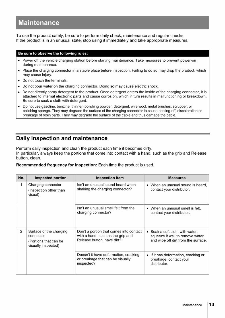
To use the product safely, be sure to perform daily check, maintenance and regular checks. If the product is in an unusual state, stop using it immediately and take appropriate measures.
Be sure to observe the following rules:
• Power off the vehicle charging station before starting maintenance. Take measures to prevent power-on during maintenance.
• Place the charging connector in a stable place before inspection. Failing to do so may drop the product, which may cause injury.
• Do not touch the terminals. • Do not pour water on the charging connector. Doing so may cause electric shock. • Do not directly spray detergent to the product. Once detergent enters the inside of the charging connector, it is
attached to internal electronic parts and cause corrosion, which in turn results in malfunctioning or breakdown. Be sure to soak a cloth with detergent.
• Do not use gasoline, benzine, thinner, polishing powder, detergent, wire wool, metal brushes, scrubber, or polishing sponge. They may degrade the surface of the charging connector to cause peeling-off, discoloration or breakage of resin parts. They may degrade the surface of the cable and thus damage the cable.
Daily inspection and maintenance Perform daily inspection and clean the product each time it becomes dirty. In particular, always keep the portions that come into contact with a hand, such as the grip and Release button, clean.
Recommended frequency for inspection: Each time the product is used.
No. Inspected portion Inspection item Measures
1 Charging connector (Inspection other than visual)
Isn’t an unusual sound heard when shaking the charging connector?
• When an unusual sound is heard, contact your distributor.
Isn’t an unusual smell felt from the charging connector?
• When an unusual smell is felt, contact your distributor.
2 Surface of the charging connector (Portions that can be visually inspected)
Don’t a portion that comes into contact with a hand, such as the grip and Release button, have dirt?
• Soak a soft cloth with water, squeeze it well to remove water and wipe off dirt from the surface.
Doesn’t it have deformation, cracking or breakage that can be visually inspected?
• If it has deformation, cracking or breakage, contact your distributor.

14 Maintenance
No. Inspected portion Inspection item Measures
3 Around or inside the housing (Other than terminals)
Doesn’t it have water drops or foreign substances attached?
• Blow off water drops or foreign substances with an air duster or blower commercially available.
• Cleaning the interior of the housing with a brush or cloth may damage terminals. Do not clean it by the method other than the above.
• If they cannot be removed by the above method, contact your distributor.
Aren’t there any packing issues such as scratch, crack or turned-up to occur?
• If it has unusual conditions, contact your distributor.
4 Terminal Doesn’t it have have water drops, dust or foreign substances attached?
• Blow off water drops, dust or foreign substances with an air duster or blower commercially available.
• If water drops or foreign substances cannot be removed by the above method, contact your distributor.
Doesn’t it have deformation or cracking that can be visually inspected?
• If it has unusual conditions, contact your distributor.
5 Cable Doesn’t it have wearing or cracking on the surface?
• If it has unusual conditions, contact your distributor.
Isn’t the internal wire exposed?
Doesn’t it have looseness at the connection with the charging connector?
Isn’t the cable twisted?
Status of twisted cable
• Rectify the twisted cable. Turn the charging connector until the cable gets untwisted. Do not pull the cable forcibly when untwisting.
How to fix a twisted cable
6 Latch Doesn’t it have deformation, cracking or wearing that can be visually inspected?
• If it has unusual conditions, contact your distributor.
Maintenance 15
No. Inspected portion Inspection item Measures
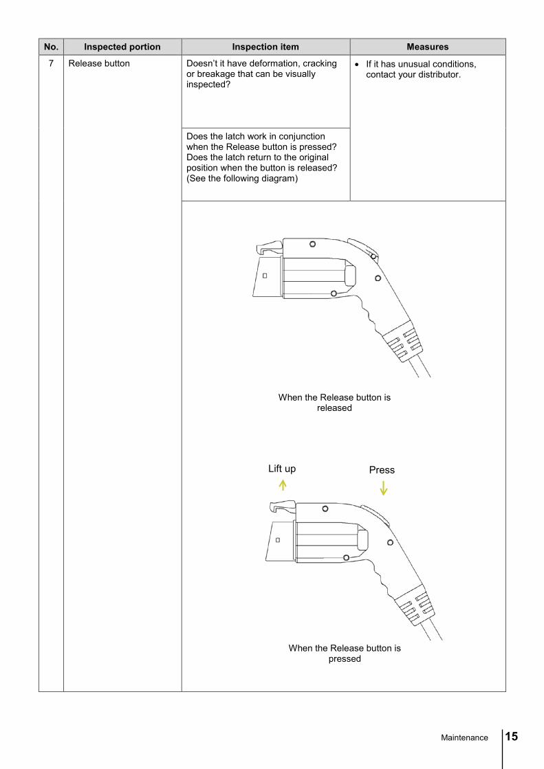
7 Release button Doesn’t it have deformation, cracking or breakage that can be visually inspected?
• If it has unusual conditions, contact your distributor.
Does the latch work in conjunction when the Release button is pressed? Does the latch return to the original position when the button is released? (See the following diagram)
When the Release button is released
Press Lift up
When the Release button is pressed

16 Maintenance
Regular checks Recommended frequency for regular checks: Once a year
No. Inspected portion Inspection item Measures
1 Terminal Isn’t terminal coating peeled off to expose the base metal?
• If the base metal is exposed, contact your distributor.
2 Insertion/pulling-out Is insertion into or pulling out from the vehicle inlet smooth?
• If it has unusual conditions, contact your distributor.
When you have a problem 17
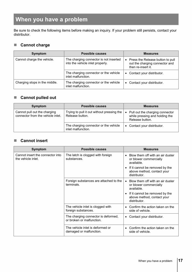
When you have a problem
Be sure to check the following items before making an inquiry. If your problem still persists, contact your distributor.
Cannot charge
Symptom Possible causes Measures
Cannot charge the vehicle. The charging connector is not inserted into the vehicle inlet properly.
• Press the Release button to pull out the charging connector and then re-insert it.
The charging connector or the vehicle inlet malfunction.
• Contact your distributor.
Charging stops in the middle. The charging connector or the vehicle inlet malfunction.
• Contact your distributor.
Cannot pulled out
Symptom Possible causes Measures
Cannot pull out the charging connector from the vehicle inlet.
Trying to pull it out without pressing the Release button.
• Pull out the charging connector while pressing and holding the Release button.
The charging connector or the vehicle inlet malfunction.
• Contact your distributor.
Cannot insert
Symptom Possible causes Measures
Cannot insert the connector into the vehicle inlet.
The latch is clogged with foreign substances.
• Blow them off with an air duster or blower commercially available.
• If it cannot be removed by the above method, contact your distributor.
Foreign substances are attached to the terminals.
• Blow them off with an air duster or blower commercially available.
• If it cannot be removed by the above method, contact your distributor.
The vehicle inlet is clogged with foreign substances.
• Confirm the action taken on the side of vehicle.
The charging connector is deformed, or broken or malfunction.
• Contact your distributor.
The vehicle inlet is deformed or damaged or malfunction.
• Confirm the action taken on the side of vehicle.

18 When you have a problem
Cannot be locked
Symptom Possible causes Measures
Can be inserted, but is readily removed.
The Release button was pressed after insertion.
• Pull out the charging connector while pressing and holding the Release button, align the guide (convex) with the groove (concave) of the vehicle inlet and then insert the housing into the vehicle inlet straight without pressing the Release button until the housing is clicked into place.
Trying to insert the connector while the Release button is held and pressed.
• Insert the connector straight until it is clicked into place without pressing and holding the Release button.
The charging connector malfunction. • Contact your distributor.
The vehicle inlet malfunction. • Confirm the action taken on the side of vehicle.
Other
Symptom Possible causes Measures
The Release button does not work.
The latch is clogged with foreign substances.
• Blow them off with an air duster or blower commercially available.
• If it cannot be removed by the above method, contact your distributor.
The Release button malfunction. • Contact your distributor.
Lip packing is come off. Deterioration of Lip Packing • Contact your distributor. (※Lippacking is a consumable.)

Specifications 19
Specifications
Japanese specifications (Rated current of 20 A)
Format Specifications
Rated voltage
Power circuit AC 250 V or less
Signal circuit 12 V or less
Rated current
Power circuit 20 A or less
Signal circuit 2 A or less
Used wire
Power circuit 2.5mm2 × 2
Signal circuit 0.75 mm2 × 1
Ground circuit 2.5mm2 × 1
Outer dimensions Width 49.8 mm × Length 204.8 mm × Height 149.3 mm Weight 450 g (Weight of a single charging connector, excluding cable)
Operating temperature -40ºC to +60ºC Insulation resistance 5 MΩ or more (DC 500 V)
Withstand voltage No insulation breakdown after application of AC 3000 V for ten seconds
Compliance laws and regulations Electrical Appliance and Material Safety Law (PSE)
Conformed standard Appendices 4-1 and 6 to Article 1 of Ministerial Ordinance for Technical Standards of Electrical Appliances
Certifying body JET
Marking
* The operating temperatures are those guaranteed by us and different from those at which safety is certified.
AC Power (L2, N) AC Power (L1)
Control pilot
Proximity Detection
Front view of housing
Equipment ground
[Terminal array] [Circuit diagram]

20 Specifications
Japanese and European specifications (Rated current of 20A)
Format Specifications
Rated voltage
Power circuit AC 250 V or less
Signal circuit 12 V or less
Rated current
Power circuit 20A or less
Signal circuit 2 A or less
Used wire
Power circuit 2.5 mm2 × 2
Signal circuit 0.75 mm2 × 1
Ground circuit 2.5 mm2 × 1
Outer dimensions Width 49.8 mm × Length 204.8 mm × Height 149.3 mm Weight 450 g (Weight of a single charging connector, excluding cable)
Operating temperature -40ºC to +60ºC Insulation resistance 5 MΩ or more (DC 500 V)
Withstand voltage No insulation breakdown after application of AC 3000 V for ten seconds
Compliance laws and regulations
・Electrical Appliance and Material Safety Law (PSE) ・Low Voltage Directive 2006/95/EC
Conformed standard ・Appendices 4-1 and 6 to Article 1 of Ministerial Ordinance for
Technical Standards of Electrical Appliances ・IEC 62196-1 Edition1.0 IEC 62196-2 Edition 1.0
Certifying body JET 、TÜV Rheinland
Marking
* The operating temperatures are those guaranteed by us and different from those at which safety is certified.
[Circuit diagram]
AC Power (L2, N) AC Power (L1)
Control pilot
Proximity Detection
Front view of housing
Equipment ground
[Terminal array]

Specifications 21
North American specifications (Rated current of 20A)
Format Specifications
Rated voltage
Power circuit AC 120/240 V or less
Signal circuit 12 V or less
Rated current
Power circuit 20 A or less
Signal circuit 2 A or less
Used wire
Power circuit 12AWG × 2
Signal circuit 18AWG× 1
Ground circuit 12AWG× 1
Outer dimensions Width 49.8 mm × Length 204.8 mm × Height 149.3 mm Weight 450 g (Weight of a single charging connector, excluding cable)
Operating temperature -40ºC to +60ºC Insulation resistance 5 MΩ or more (DC 500 V)
Withstand voltage No insulation breakdown after application of AC 3000 V for ten seconds
Compliance laws and regulations National Electrical Code NFPA 70
Conformed standard UL2251 Second Edition Certifying body Underwriters Laboratories
Marking
* The operating temperatures are those guaranteed by us and different from those at which safety is certified.
AC Power (L2, N) AC Power (L1)
Control pilot
Proximity Detection
Front view of housing
Equipment ground
[Terminal array] [Circuit diagram]

22 Specifications
North American specifications (Rated current of 30 A)
Format Specifications
Rated voltage
Power circuit AC 120/240V or less
Signal circuit 12 V or less
Rated current
Power circuit 30 A or less
Signal circuit 2 A or less
Used wire
Power circuit 10AWG × 2
Signal circuit 18AWG × 1
Ground circuit 10AWG × 1
Outer dimensions Width 49.8 mm × Length 204.8 mm × Height 149.3 mm Weight 450 g (Weight of a single charging connector, excluding cable)
Operating temperature -40ºC to +60ºC Insulation resistance 5 MΩ or more (DC 500 V)
Withstand voltage No insulation breakdown after application of AC 3000 V for ten seconds
Compliance laws and regulations National Electrical Code NFPA 70
Conformed standard UL2251 Second Edition Certifying body Underwriters Laboratories
Marking
* The operating temperatures are those guaranteed by us and different from those at which safety is certified.
AC Power (L2, N) AC Power (L1)
Control pilot
Proximity Detection
Front view of housing
Equipment ground
[Terminal array] [Circuit diagram]

Warranty 23
Warranty [AC Charging Connector of TYPE 1 (T1V-02)]
This product, AC Charging Connector, is produced utilizing strict quality control and rigorous inspection methods. Should your product malfunction under normal use conditions, this document guarantees that services will be provided without any charge commensurate with the following conditions:
Period and scope of warranty
1. Warranty period: This product is covered for service for one year from the manufacturing date. In case of 2), 3), 4) or 5) of 3, services are provided at the customer's expense. If a warranty period is separately agreed upon with our sales representative or distributor, this separate agreement shall prevail. How to confirm manufacturing date • The manufacturing date is determined from the serial number printed on the product. • The serial number is printed on the side face of your charging connector under the
certification mark. • How to read a manufacturing date from a serial number Ex)
13 01 23 - 001 [1] [2] [3] [4] [1] 13: Indicates the year of 2013. [2] 01: Indicates the month of January [3] 23: Indicates the 23rd day. [4] 001: Manufactured first on the day indicated by [1], [2] and [3].
2. After the warranty period: Services are provided at the customer's expense. For malfunctioning or breakage due to our defect in design or manufacture, services will be provided without any charge to the customer.
3. For malfunctioning or breakage due to the following causes, repair services will only be provided at the customer's expense. 1) Malfunctioning or breakage of a product after the expiration of the warranty period 2) Malfunctioning or breakage due to abuse, installation or transportation performed by
the customer. 3) Malfunctioning or breakage due to repair or alternation using parts other than those
specified by Yazaki Corporation. 4) Malfunctioning or breakage due to repair or alternation performed by service providers
other than Yazaki or designated by Yazaki. 5) Malfunctioning or breakage due to natural disaster, such as earthquake and fire, or
other force majeure 4. Yazaki Corporation will not compensate for any secondary damage, including injury of a
user or damage to other equipment or property, caused by an accident arising out of or in connection with operation methods other than those set forth in this Operation Manual.
* This warranty guarantees that we will provide services without any charge for the period and under the conditions set forth herein. This warranty does not limit the legal rights of customers against the issuer of this warranty (company responsible for warranty) and other operators.
* For services provided after the expiration of the warranty period and replacement parts retention periods, contact your distributor or our sales representative.
YAZAKI Corporation
Yazaki Parts Co., Ltd. 17th Floor, Mita-Kokusai Bldg., 4-28 Mita 1-chome, Minato-ku, Tokyo