ac 20-30b - aircraft position light and anticollision ... · advisory circular ac 20-74, aircraft...
TRANSCRIPT

OC tjOq
middot j
AC 20-308
DATE 72081
ADVISORY CIRCULAR DEPARTMENT OF TRANSPORTATION
Federal Aviation Administration
Washington DC
FAR GUIDANCE MATERIAL
SubjectAIRCAAFT POSITION LIGHI AND ANTICOLLISION LIGHT INSTALLATIONS
1 PURPOSE his circular sets forth acceptable ireans but oot the ooly means of showing compliance with the Federal Aviation Regulations (FAR) awlicable to installed IX)Sition lights and antioollision lights
2 CANELIATION AC 20-30A dated April 18 1968 is canceled
3 REIATED FAR SFcTIONS
a Sections bull1385 through 1401 of FAR Parts 23 25 27 and 29
b Sections 33 and 73 of FAR Part 91
4 REIATED READING MATERIAL
a Advisory Circular AC 20-74 Aircraft Position Lights and Antioollision Light Measurements
b Advisory Circular AC 4313-2A Acceptable Methods Techniques and Practices Aircraft Alterations
c Technical Standard Order (ISO) C30b Aircraft Position Lights
5 BACKGROUND Airworthiness regulations and Technical Standard Orders prescribe minimum intensities light distribution overlap limits allowable obstructions to light visibility and oolor for IX)Sition lights and antioollision lights
6 IABORAIORY MEASUREMENTS Measurements of intensity light distribution and Iignt oolor are normally made under laboratory oonditions tefore installation Advisory Circular 20-74 oontains information ooncerning measurements of intensity distribution and oolor
Initiated by AWS-100
AC 20-30B 72081
7 OOSITION LIGlIT SYSTEM INSTALLATION
a Location In determining whether forward position lights have been spaced laterally as far apart as practicable and whether the rear position light has been mounted as far aft as practicable as required by the FAR s each installation may be evaluated for special considerations Examples of special consideration are
(1) Would the number of malfunctions be significantly increased due to increased vibration or other environmental conditions if the lights were spaced farther apart or munted farther aft
(2) Would accessibility for maintenance be significantly reduced if the lights ~re spaced farther apart or farther aft
b Rear Position Light Obstructions A small light obstruction is pershymitted within dihedral angle A (aft) described insect 1387(d) of Parts 23 25 27 and 29 That obstruction is limited in size to O04 steradian and in position to the 30deg cone described insect 1387(e) of Parts 23 25 27 and 29 and shown in Figure 1 ~asurements to show compliance with the regulations can be made on actual aircraft or on appropriate scale drawings The following procedure is one rreans of showing compliance with the regulations
(1) On the side view drawing draw a line through the light center perpendicular to the aircraft longitudinal axis Draw a second line upward through the light center to the mst aft point en the vertical stabilizer The angle z between the tfrac14O lines is limited by the airworthiness rules to 30deg Figure 1 shows an example of angle Z
(2) On the rear view drawing draw angle W which is fanned by two lines drawn upward from the light center to the maxinnJm right and left obstructions within angle z When a protrusion causes a very small zone of obstruction it may be discounted unless total obstructions are near the regulatory limit When a rear view drawing is rot available a combination of other drawings or measurements on the actual aircraft can be used to detemine angle w
(3) Multiply angle z degrees by angle Wdegrees to obtain the amount of obstruction in square degrees The rrethod is conservative as obstructions as wide as angle Wmay rot exist throughout angle Z Convert the rreasurement to steradians by dividing the square degree value by 3284 The number 3284 is a conversion factor to obtain steradians from square degrees
8 ANTICOUISION LIGlITS
a Airworthiness Requirements Appendix 1 Tables 3 through 6 summarize the airworthiness requirements for anticollision lights and lists them according to the applicable amendments to the CARsFARs The airworthiness requirements for a specific aircraft can usually be determined by entering the applicable table with the latest amendment shown for the certification basis in the aircrafts type certificate data sheet
Par 7 2
72081 AC 20-30B
FIGURE 1 REAR POSITION LIGHT OBSTRUCTIONS
DIHEDRAL ANGLE
iz I I I __
RUDDER
REAR VIEW
3
AC2Q-30B 72081
b Operational Requirements SOme airworthiness requirements have been made retroactive by Amendment 91-90 which amended sect 9133(c)(3) of the F7R The tenn initially installed used in this section refers to new installations based on newly-approved design dnta or any installation bich includes a major change as defined in FAR 2193(a) to the previously approved design data In effect new designs bich have had m previous FAA approval are considered initially installed systems Anticollision light installations approved by Major Repair and Alteration (Airframe Powerplant Propeller or Appliance) FAA Fbnn 337 supplemental type certificate or amended type certificate prior to August 11 1971 may be duplicated on like make and nodel aircraft without being considered initially installed
c Cbstruction Measurements When anticollision light oostructions are allowed within the required field of coverage measurements on shadows scale drawings or actual aircraft can be used to substantiate that solid angles of obstruction do mt exceed regulatory limits When masking is used to prevent the iropainnent of crew vision the mask becomes an additional light obstruction Ihe arrount of obstruction caused by the mask depends mt only on the physical size of the mask but also on the type and size of the light source With rotating beacons the mask obstruction may be slightly larger than indicated by the physical size of the mask his condition results fran the lack of a sharp cutoff of light at the mask edges As the reflector rotates there is a gradual reduction of light near the mask edges due to the relatively large size of the light source Accurate rceasurernent of mask obstruction can best be accomplished during the laooratory measurement of intensity and field of coverage otherwise total oostructions measured very near the regulatory limit may actually exceed that limit
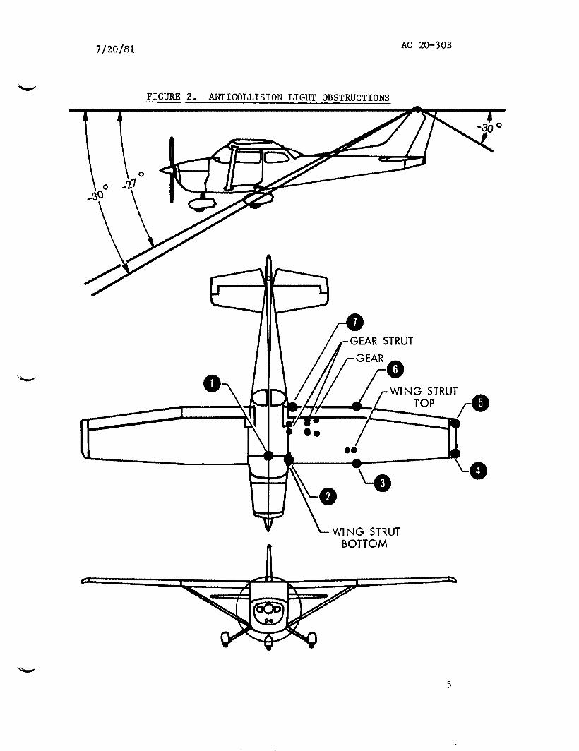
d Ihe following procedures refer to the example shown in Figure 2 Scale drawings and measurements from the light unit are used in substantiating compliance with the anticollision light requirements Ihe procedure with variations can be applied to other aircraft Variations include other shapes and vertical coverage requirements Ihe procedure converts scale drawing obstructions to a plot of oorizontal versus vertical degrees here area units become sJUare degrees By counting the squares within cbstructions and converting the sum to steradians compliance can be shown Scale drawings should be large enough to assure reasonable accuracy in the measurements For the example the vertical coverage requirement is +30deg
(1) Fuselage and Wings
(i) Point selection On the top view establish enough pgtints to adequately follow the shape of cbstructions In the example of Figure 2 seven pgtints are established and numbered to represent the left half of the fuselage and the left wing Because of symnetry measurements are limited to one side and the measured cbstructed area is doubled to account for the other side of the aircraft Additional dgtstructions mt represented by the seven numbered pgtints include mask wing struts landing gear and rudder These additional cbstructions are considered separately
Par 8 4
AC 20-30B72081
FIGURE 2 ANTICOLLISION LIGHT OBSTRUCTIONS
0
bullbull _9
WING STRUT
-0
BOTTOM
5
AC 20-30B 72081
() LLJ LLJ 0 () LLJ 0
-I lt( I-z 0 N 0 0 c
FIGURE 3
0 IO I
ANTICOLLISION LIGHT 0
-1shy
_
-
~
bull bull
-_
1
0 z 3
IA
I
II
shyLoi
II_ H
gt 0 IshyV)
_ 0II z 3
~t
ftl-
II
Ill
middot- ~ V)
1 I
1
Ill
()
1-shy
z~ 0 lt( zw
5 0_ -shyI shy gt -li0 I- - V) -
I shy0 middotshylt( pw 0
_
shy
I shy
~
_ -shy _
t
deg
0 IO
0 cent
IO M
0 M
IO N
0 N
IO
~ bullr
_
-
~~
IO N
I
0
IO
0 0 M
I
0 IO 0 N I I I
S33H83G 1fll 1H3
OBSTRUCTED AREAS
6
72081 AC 20-30B
(ii) Horizontal 19les On the top view of Figure 2 measure the horizontal angles between the aircraft centerline and lines connecting the anticollision light center to the numbered ioints
(iii) Vertical at9les On the side view of Figure 2 measure the vertical angles from the horizontal plane passing through the anticollision light center to lines connecting the light center to the numbered ioints
(iv) Tabulation Tabulate the measured horizontal and vertical angles as shown in Table 1
NarE In lieu of direct angle measurements distance measurements may be used to calculate the angles using trigonometry relationships
(2) Wiryg strut angles On the top view of Figure 2 establish right and left ioints for the strut top and fore and aft ioints for the strut lxgtttom Horizontal angles for the strut lxgtttom points are approximately equal Measure the horizontal and vertical angles to the four pgtints and tabulate as shown in Table 1
(3) Main 1ear fairi~ On the top of Figure 2 establish four pgtints for the main gearairing obstruction he rear obstruction limit is the -30deg vertical coverage requirement and the forward obstruction extends to vertical angles of -27deg he effect of wheel fairing rounding is slight and is neglected Measure the horizontal angles to the four pgtints and tabulate as shown in Table 1
(4) Main gear strut On the top view of Figure 2 establish four points for the main gear strut Measure the horizontal and vertical angles to the four pgtints and tabulate as shown in Table 1
(5) Rudder obstructions On the side view of Figure 2 rudder dgttstrucshytions occur aft of the anticollision light frac14bile all other obstructions are forward lherefore it is practical to measure rudder obstructions independently On the side view of Figure 2 the rudder obstructs for 30 vertical degrees Q1 the top view the obstruction is 3 horizontal degrees on the left side he left side rudder obstruction is 90 square degrees ie 30deg x 3deg = 90 square degrees
(6) Calculating obstructions he grap1 of Figure 3 shows plotting of the collected data of Table 1 as vertical degrees versus horizontal degrees Each square is equal to one square degree so that obstructions can be measured by counting squares Obstruction areas can be counted in zones rounded by vertical lines through the numbered pgtints Table 2 shows the counts including the rudder obstruction which was measured independent of the grap1 Square degrees are converted to steradians by dividing by 3284
Director of Airworthiness
Par 8 7
72081 AC 20-30B Appendix 1
-~ TABLE 1 OBSTRUCTION POINT ANGLES
OBSTRUCTION
WingFuselage
Strut
Gear
Gear Strut )
Mask (Positioned to eliminate reflections from prop)
POINT
1 2 3 4 5 6 7
Top Right Top Left Bottom Upper Bottom Lower
Front Right Front Left Rear Right Rear Left
Top Front Top Rear Bottom Front Bottom Rear
Top Centerline Top Left Bottom Centerline Bottom Left
HORIZONTAL VERTICAL ANGLE ANGLE
oo -75deg 70 -70deg
25deg -55deg 47deg -75deg 52deg -12deg 32deg -13deg
ao -12deg
22deg -85deg 24deg -90deg 70 -22deg 70 -235deg
12deg -27deg 155deg -27deg 13deg -30deg 165deg -30deg
ao -24deg so -25deg
130 -2s5deg 13deg -295deg
oo -10deg 10deg -10deg oo -30deg
10deg -30deg
1
AC 20-30B 72081 Appendix 1
TABLE 2 OBSTRUCTION COUNT
zam SQUARE DEGREES
Point 1 to Point 2 159 Point 2 to Point 3 198 Point 3 to Point 4 132 Point 4 to Point 5 14
Total Grapi 503 Rudder 90
Total Left Side 593
TOIAL AIRPIANE 1186
Steradians (11863284) = 036
2
---
0
(
TABLE 3 FAR 23CAR 3 N -
CXl -I-
APPLICABLE INTENSITY VERTICAL COLOR FLASH LIGHT AMENDMENTS (CANDLES) COVERAGE SPECS RATE OBSTRUCTION REMARKS
1 Before 3-1 No Anticollision (4157) Light Requirements
2 Thru 3-1 100 +30 Aviation Red 40-100 003 STER Position of Allowable (4157) overlap 180 015 STER Obstruction Limited
3 Thru 3-7 100 +30 Aviation Red 40-100 05 STER (5362) overlap 180
4 Thru 23-11 400 +30 Aviation Red or 40-100 05 STER New Aviation White (81171) Aviation White overlap 180 Limits
5 Thru 23-20 400 +75 Aviation Red or 40-100 o5 STER ( 9177) Aviation White overlap 180
NOTE 9133(c)(3) of the FAR also applies to anticollision light installations and allows the color to be either aviation red or aviation white
I-
TABLE 4 FAR 25CAR 4b
APPLICABLE INTENSITY VERTICAL COLOR FLASH LIGHT AMENDMENTS (CANDLES) COVERAGE SPECS RATE OBSTRUCTION REMARKS
1 Before 4b-8 No Anticollision ( 51653) Light Requirements
2 Thru 4b-8 If Used If Used If Used On-Off ratio (51653) Aviation Red 40-100 Not less than 175
3 Thru 4b-3 If Used If Used If Used On-Off ratio ( 31356) Aviation Red 40-100 Not less than 175
If Extra Light Installed No Flash Rate Limit in overlaps
4 Thru 4b-4 100 +30 Aviation Red 40-100 003 STER Position of Allowable (4157) overlap 180 015 STER Obstruction Limited
5 Thru 25-27 400 +30 Aviation Red or 40-100 003 STER New Aviation White
( 81171) Aviation White overlap 180 015 STER Limits shy(X) -N
6 Thru 25-41 400 +75 Aviation Red or 40-100 003 STER
( 9177) Aviation White overlap 180 015 STER
NOTE 9133(c)(3) of the FAR also applies to anticollision light installations and allows the
color to be either aviation red or aviation white
0
---
( (
-0 TABLE 5bull FAR 27CAR 6
()) -N
APPLICABLE INTENSITY VERTICAL COLOR FLASH LIGHT AMENDMENTS (CANDLES) COVERAGE SPECS RATE OBSTRUCTION REMARKS
1 Before Part 6 No Anticollision (4157) Light Requirements
2 Thru 6-1 100 +30 Aviation Red 40-100 003 STER (4157) overlaps 180
3 Thru 6-5 100 +30 Aviation Red 40-100 005 STER (5362) overlaps 180
4 Thru 27-6 400 +30 Aviation Red or 40-100 05 STER New Aviation White (81171) Aviation White overlaps 180 Limits
5 Thru 27-10 150 +30 Aviation Red 40-100 05 STER Aviation White not (2576) overlaps 180 acceptable
NOTE 9133(c)(3) of the FAR also applies to anticolision light installations and allows the
color to be either aviation red or aviation white
6~ to CD N i 0 0 I w gtlt 0
0 I-
TABLE 6 FAR 29CAR 7
APPLICABLE INTENSITY VERTICAL COLOR FLASH LIGHT AMENDMENTS (CANDLES) COVERAGE SPECS RATE OBSTRUCTION REMARKS
1 Before Part 7 No Anticollision (8156) Light Requirement
2 Adopt Part 7 None None None None None Approved Anticollision Light Required
3 Thru 7-1 100 +~u Aviation Red 40-100 003 STER Obstruction Position
gt (4157) overlaps 180 Not limited C ()
Cl 0 4 Thru 7-5 100 +30 Aviation Red 40-100 05 STER lt
(5562) overlaps 180 m z r m z --i z --i
Cl z 5 Thru 29-7 400 +30 Aviation Red or 40-100 o5 STER New Aviation White 0 (81171) Aviation White overlaps 180 Limits 1i m
6 Thru 29-11 150 +30 Aviation Red 40-100 o5 STER Aviation White not (2576) Overlaps 180 acceptable
-NOTE 9133(c)(3) of the FAR also applies to anticollision light installations and allows the 0
color to be either aviation red or aviation white -I-
N
00

AC 20-30B 72081
7 OOSITION LIGlIT SYSTEM INSTALLATION
a Location In determining whether forward position lights have been spaced laterally as far apart as practicable and whether the rear position light has been mounted as far aft as practicable as required by the FAR s each installation may be evaluated for special considerations Examples of special consideration are
(1) Would the number of malfunctions be significantly increased due to increased vibration or other environmental conditions if the lights were spaced farther apart or munted farther aft
(2) Would accessibility for maintenance be significantly reduced if the lights ~re spaced farther apart or farther aft
b Rear Position Light Obstructions A small light obstruction is pershymitted within dihedral angle A (aft) described insect 1387(d) of Parts 23 25 27 and 29 That obstruction is limited in size to O04 steradian and in position to the 30deg cone described insect 1387(e) of Parts 23 25 27 and 29 and shown in Figure 1 ~asurements to show compliance with the regulations can be made on actual aircraft or on appropriate scale drawings The following procedure is one rreans of showing compliance with the regulations
(1) On the side view drawing draw a line through the light center perpendicular to the aircraft longitudinal axis Draw a second line upward through the light center to the mst aft point en the vertical stabilizer The angle z between the tfrac14O lines is limited by the airworthiness rules to 30deg Figure 1 shows an example of angle Z
(2) On the rear view drawing draw angle W which is fanned by two lines drawn upward from the light center to the maxinnJm right and left obstructions within angle z When a protrusion causes a very small zone of obstruction it may be discounted unless total obstructions are near the regulatory limit When a rear view drawing is rot available a combination of other drawings or measurements on the actual aircraft can be used to detemine angle w
(3) Multiply angle z degrees by angle Wdegrees to obtain the amount of obstruction in square degrees The rrethod is conservative as obstructions as wide as angle Wmay rot exist throughout angle Z Convert the rreasurement to steradians by dividing the square degree value by 3284 The number 3284 is a conversion factor to obtain steradians from square degrees
8 ANTICOUISION LIGlITS
a Airworthiness Requirements Appendix 1 Tables 3 through 6 summarize the airworthiness requirements for anticollision lights and lists them according to the applicable amendments to the CARsFARs The airworthiness requirements for a specific aircraft can usually be determined by entering the applicable table with the latest amendment shown for the certification basis in the aircrafts type certificate data sheet
Par 7 2
72081 AC 20-30B
FIGURE 1 REAR POSITION LIGHT OBSTRUCTIONS
DIHEDRAL ANGLE
iz I I I __
RUDDER
REAR VIEW
3
AC2Q-30B 72081
b Operational Requirements SOme airworthiness requirements have been made retroactive by Amendment 91-90 which amended sect 9133(c)(3) of the F7R The tenn initially installed used in this section refers to new installations based on newly-approved design dnta or any installation bich includes a major change as defined in FAR 2193(a) to the previously approved design data In effect new designs bich have had m previous FAA approval are considered initially installed systems Anticollision light installations approved by Major Repair and Alteration (Airframe Powerplant Propeller or Appliance) FAA Fbnn 337 supplemental type certificate or amended type certificate prior to August 11 1971 may be duplicated on like make and nodel aircraft without being considered initially installed
c Cbstruction Measurements When anticollision light oostructions are allowed within the required field of coverage measurements on shadows scale drawings or actual aircraft can be used to substantiate that solid angles of obstruction do mt exceed regulatory limits When masking is used to prevent the iropainnent of crew vision the mask becomes an additional light obstruction Ihe arrount of obstruction caused by the mask depends mt only on the physical size of the mask but also on the type and size of the light source With rotating beacons the mask obstruction may be slightly larger than indicated by the physical size of the mask his condition results fran the lack of a sharp cutoff of light at the mask edges As the reflector rotates there is a gradual reduction of light near the mask edges due to the relatively large size of the light source Accurate rceasurernent of mask obstruction can best be accomplished during the laooratory measurement of intensity and field of coverage otherwise total oostructions measured very near the regulatory limit may actually exceed that limit
d Ihe following procedures refer to the example shown in Figure 2 Scale drawings and measurements from the light unit are used in substantiating compliance with the anticollision light requirements Ihe procedure with variations can be applied to other aircraft Variations include other shapes and vertical coverage requirements Ihe procedure converts scale drawing obstructions to a plot of oorizontal versus vertical degrees here area units become sJUare degrees By counting the squares within cbstructions and converting the sum to steradians compliance can be shown Scale drawings should be large enough to assure reasonable accuracy in the measurements For the example the vertical coverage requirement is +30deg
(1) Fuselage and Wings
(i) Point selection On the top view establish enough pgtints to adequately follow the shape of cbstructions In the example of Figure 2 seven pgtints are established and numbered to represent the left half of the fuselage and the left wing Because of symnetry measurements are limited to one side and the measured cbstructed area is doubled to account for the other side of the aircraft Additional dgtstructions mt represented by the seven numbered pgtints include mask wing struts landing gear and rudder These additional cbstructions are considered separately
Par 8 4
AC 20-30B72081
FIGURE 2 ANTICOLLISION LIGHT OBSTRUCTIONS
0
bullbull _9
WING STRUT
-0
BOTTOM
5
AC 20-30B 72081
() LLJ LLJ 0 () LLJ 0
-I lt( I-z 0 N 0 0 c
FIGURE 3
0 IO I
ANTICOLLISION LIGHT 0
-1shy
_
-
~
bull bull
-_
1
0 z 3
IA
I
II
shyLoi
II_ H
gt 0 IshyV)
_ 0II z 3
~t
ftl-
II
Ill
middot- ~ V)
1 I
1
Ill
()
1-shy
z~ 0 lt( zw
5 0_ -shyI shy gt -li0 I- - V) -
I shy0 middotshylt( pw 0
_
shy
I shy
~
_ -shy _
t
deg
0 IO
0 cent
IO M
0 M
IO N
0 N
IO
~ bullr
_
-
~~
IO N
I
0
IO
0 0 M
I
0 IO 0 N I I I
S33H83G 1fll 1H3
OBSTRUCTED AREAS
6
72081 AC 20-30B
(ii) Horizontal 19les On the top view of Figure 2 measure the horizontal angles between the aircraft centerline and lines connecting the anticollision light center to the numbered ioints
(iii) Vertical at9les On the side view of Figure 2 measure the vertical angles from the horizontal plane passing through the anticollision light center to lines connecting the light center to the numbered ioints
(iv) Tabulation Tabulate the measured horizontal and vertical angles as shown in Table 1
NarE In lieu of direct angle measurements distance measurements may be used to calculate the angles using trigonometry relationships
(2) Wiryg strut angles On the top view of Figure 2 establish right and left ioints for the strut top and fore and aft ioints for the strut lxgtttom Horizontal angles for the strut lxgtttom points are approximately equal Measure the horizontal and vertical angles to the four pgtints and tabulate as shown in Table 1
(3) Main 1ear fairi~ On the top of Figure 2 establish four pgtints for the main gearairing obstruction he rear obstruction limit is the -30deg vertical coverage requirement and the forward obstruction extends to vertical angles of -27deg he effect of wheel fairing rounding is slight and is neglected Measure the horizontal angles to the four pgtints and tabulate as shown in Table 1
(4) Main gear strut On the top view of Figure 2 establish four points for the main gear strut Measure the horizontal and vertical angles to the four pgtints and tabulate as shown in Table 1
(5) Rudder obstructions On the side view of Figure 2 rudder dgttstrucshytions occur aft of the anticollision light frac14bile all other obstructions are forward lherefore it is practical to measure rudder obstructions independently On the side view of Figure 2 the rudder obstructs for 30 vertical degrees Q1 the top view the obstruction is 3 horizontal degrees on the left side he left side rudder obstruction is 90 square degrees ie 30deg x 3deg = 90 square degrees
(6) Calculating obstructions he grap1 of Figure 3 shows plotting of the collected data of Table 1 as vertical degrees versus horizontal degrees Each square is equal to one square degree so that obstructions can be measured by counting squares Obstruction areas can be counted in zones rounded by vertical lines through the numbered pgtints Table 2 shows the counts including the rudder obstruction which was measured independent of the grap1 Square degrees are converted to steradians by dividing by 3284
Director of Airworthiness
Par 8 7
72081 AC 20-30B Appendix 1
-~ TABLE 1 OBSTRUCTION POINT ANGLES
OBSTRUCTION
WingFuselage
Strut
Gear
Gear Strut )
Mask (Positioned to eliminate reflections from prop)
POINT
1 2 3 4 5 6 7
Top Right Top Left Bottom Upper Bottom Lower
Front Right Front Left Rear Right Rear Left
Top Front Top Rear Bottom Front Bottom Rear
Top Centerline Top Left Bottom Centerline Bottom Left
HORIZONTAL VERTICAL ANGLE ANGLE
oo -75deg 70 -70deg
25deg -55deg 47deg -75deg 52deg -12deg 32deg -13deg
ao -12deg
22deg -85deg 24deg -90deg 70 -22deg 70 -235deg
12deg -27deg 155deg -27deg 13deg -30deg 165deg -30deg
ao -24deg so -25deg
130 -2s5deg 13deg -295deg
oo -10deg 10deg -10deg oo -30deg
10deg -30deg
1
AC 20-30B 72081 Appendix 1
TABLE 2 OBSTRUCTION COUNT
zam SQUARE DEGREES
Point 1 to Point 2 159 Point 2 to Point 3 198 Point 3 to Point 4 132 Point 4 to Point 5 14
Total Grapi 503 Rudder 90
Total Left Side 593
TOIAL AIRPIANE 1186
Steradians (11863284) = 036
2
---
0
(
TABLE 3 FAR 23CAR 3 N -
CXl -I-
APPLICABLE INTENSITY VERTICAL COLOR FLASH LIGHT AMENDMENTS (CANDLES) COVERAGE SPECS RATE OBSTRUCTION REMARKS
1 Before 3-1 No Anticollision (4157) Light Requirements
2 Thru 3-1 100 +30 Aviation Red 40-100 003 STER Position of Allowable (4157) overlap 180 015 STER Obstruction Limited
3 Thru 3-7 100 +30 Aviation Red 40-100 05 STER (5362) overlap 180
4 Thru 23-11 400 +30 Aviation Red or 40-100 05 STER New Aviation White (81171) Aviation White overlap 180 Limits
5 Thru 23-20 400 +75 Aviation Red or 40-100 o5 STER ( 9177) Aviation White overlap 180
NOTE 9133(c)(3) of the FAR also applies to anticollision light installations and allows the color to be either aviation red or aviation white
I-
TABLE 4 FAR 25CAR 4b
APPLICABLE INTENSITY VERTICAL COLOR FLASH LIGHT AMENDMENTS (CANDLES) COVERAGE SPECS RATE OBSTRUCTION REMARKS
1 Before 4b-8 No Anticollision ( 51653) Light Requirements
2 Thru 4b-8 If Used If Used If Used On-Off ratio (51653) Aviation Red 40-100 Not less than 175
3 Thru 4b-3 If Used If Used If Used On-Off ratio ( 31356) Aviation Red 40-100 Not less than 175
If Extra Light Installed No Flash Rate Limit in overlaps
4 Thru 4b-4 100 +30 Aviation Red 40-100 003 STER Position of Allowable (4157) overlap 180 015 STER Obstruction Limited
5 Thru 25-27 400 +30 Aviation Red or 40-100 003 STER New Aviation White
( 81171) Aviation White overlap 180 015 STER Limits shy(X) -N
6 Thru 25-41 400 +75 Aviation Red or 40-100 003 STER
( 9177) Aviation White overlap 180 015 STER
NOTE 9133(c)(3) of the FAR also applies to anticollision light installations and allows the
color to be either aviation red or aviation white
0
---
( (
-0 TABLE 5bull FAR 27CAR 6
()) -N
APPLICABLE INTENSITY VERTICAL COLOR FLASH LIGHT AMENDMENTS (CANDLES) COVERAGE SPECS RATE OBSTRUCTION REMARKS
1 Before Part 6 No Anticollision (4157) Light Requirements
2 Thru 6-1 100 +30 Aviation Red 40-100 003 STER (4157) overlaps 180
3 Thru 6-5 100 +30 Aviation Red 40-100 005 STER (5362) overlaps 180
4 Thru 27-6 400 +30 Aviation Red or 40-100 05 STER New Aviation White (81171) Aviation White overlaps 180 Limits
5 Thru 27-10 150 +30 Aviation Red 40-100 05 STER Aviation White not (2576) overlaps 180 acceptable
NOTE 9133(c)(3) of the FAR also applies to anticolision light installations and allows the
color to be either aviation red or aviation white
6~ to CD N i 0 0 I w gtlt 0
0 I-
TABLE 6 FAR 29CAR 7
APPLICABLE INTENSITY VERTICAL COLOR FLASH LIGHT AMENDMENTS (CANDLES) COVERAGE SPECS RATE OBSTRUCTION REMARKS
1 Before Part 7 No Anticollision (8156) Light Requirement
2 Adopt Part 7 None None None None None Approved Anticollision Light Required
3 Thru 7-1 100 +~u Aviation Red 40-100 003 STER Obstruction Position
gt (4157) overlaps 180 Not limited C ()
Cl 0 4 Thru 7-5 100 +30 Aviation Red 40-100 05 STER lt
(5562) overlaps 180 m z r m z --i z --i
Cl z 5 Thru 29-7 400 +30 Aviation Red or 40-100 o5 STER New Aviation White 0 (81171) Aviation White overlaps 180 Limits 1i m
6 Thru 29-11 150 +30 Aviation Red 40-100 o5 STER Aviation White not (2576) Overlaps 180 acceptable
-NOTE 9133(c)(3) of the FAR also applies to anticollision light installations and allows the 0
color to be either aviation red or aviation white -I-
N
00

72081 AC 20-30B
FIGURE 1 REAR POSITION LIGHT OBSTRUCTIONS
DIHEDRAL ANGLE
iz I I I __
RUDDER
REAR VIEW
3
AC2Q-30B 72081
b Operational Requirements SOme airworthiness requirements have been made retroactive by Amendment 91-90 which amended sect 9133(c)(3) of the F7R The tenn initially installed used in this section refers to new installations based on newly-approved design dnta or any installation bich includes a major change as defined in FAR 2193(a) to the previously approved design data In effect new designs bich have had m previous FAA approval are considered initially installed systems Anticollision light installations approved by Major Repair and Alteration (Airframe Powerplant Propeller or Appliance) FAA Fbnn 337 supplemental type certificate or amended type certificate prior to August 11 1971 may be duplicated on like make and nodel aircraft without being considered initially installed
c Cbstruction Measurements When anticollision light oostructions are allowed within the required field of coverage measurements on shadows scale drawings or actual aircraft can be used to substantiate that solid angles of obstruction do mt exceed regulatory limits When masking is used to prevent the iropainnent of crew vision the mask becomes an additional light obstruction Ihe arrount of obstruction caused by the mask depends mt only on the physical size of the mask but also on the type and size of the light source With rotating beacons the mask obstruction may be slightly larger than indicated by the physical size of the mask his condition results fran the lack of a sharp cutoff of light at the mask edges As the reflector rotates there is a gradual reduction of light near the mask edges due to the relatively large size of the light source Accurate rceasurernent of mask obstruction can best be accomplished during the laooratory measurement of intensity and field of coverage otherwise total oostructions measured very near the regulatory limit may actually exceed that limit
d Ihe following procedures refer to the example shown in Figure 2 Scale drawings and measurements from the light unit are used in substantiating compliance with the anticollision light requirements Ihe procedure with variations can be applied to other aircraft Variations include other shapes and vertical coverage requirements Ihe procedure converts scale drawing obstructions to a plot of oorizontal versus vertical degrees here area units become sJUare degrees By counting the squares within cbstructions and converting the sum to steradians compliance can be shown Scale drawings should be large enough to assure reasonable accuracy in the measurements For the example the vertical coverage requirement is +30deg
(1) Fuselage and Wings
(i) Point selection On the top view establish enough pgtints to adequately follow the shape of cbstructions In the example of Figure 2 seven pgtints are established and numbered to represent the left half of the fuselage and the left wing Because of symnetry measurements are limited to one side and the measured cbstructed area is doubled to account for the other side of the aircraft Additional dgtstructions mt represented by the seven numbered pgtints include mask wing struts landing gear and rudder These additional cbstructions are considered separately
Par 8 4
AC 20-30B72081
FIGURE 2 ANTICOLLISION LIGHT OBSTRUCTIONS
0
bullbull _9
WING STRUT
-0
BOTTOM
5
AC 20-30B 72081
() LLJ LLJ 0 () LLJ 0
-I lt( I-z 0 N 0 0 c
FIGURE 3
0 IO I
ANTICOLLISION LIGHT 0
-1shy
_
-
~
bull bull
-_
1
0 z 3
IA
I
II
shyLoi
II_ H
gt 0 IshyV)
_ 0II z 3
~t
ftl-
II
Ill
middot- ~ V)
1 I
1
Ill
()
1-shy
z~ 0 lt( zw
5 0_ -shyI shy gt -li0 I- - V) -
I shy0 middotshylt( pw 0
_
shy
I shy
~
_ -shy _
t
deg
0 IO
0 cent
IO M
0 M
IO N
0 N
IO
~ bullr
_
-
~~
IO N
I
0
IO
0 0 M
I
0 IO 0 N I I I
S33H83G 1fll 1H3
OBSTRUCTED AREAS
6
72081 AC 20-30B
(ii) Horizontal 19les On the top view of Figure 2 measure the horizontal angles between the aircraft centerline and lines connecting the anticollision light center to the numbered ioints
(iii) Vertical at9les On the side view of Figure 2 measure the vertical angles from the horizontal plane passing through the anticollision light center to lines connecting the light center to the numbered ioints
(iv) Tabulation Tabulate the measured horizontal and vertical angles as shown in Table 1
NarE In lieu of direct angle measurements distance measurements may be used to calculate the angles using trigonometry relationships
(2) Wiryg strut angles On the top view of Figure 2 establish right and left ioints for the strut top and fore and aft ioints for the strut lxgtttom Horizontal angles for the strut lxgtttom points are approximately equal Measure the horizontal and vertical angles to the four pgtints and tabulate as shown in Table 1
(3) Main 1ear fairi~ On the top of Figure 2 establish four pgtints for the main gearairing obstruction he rear obstruction limit is the -30deg vertical coverage requirement and the forward obstruction extends to vertical angles of -27deg he effect of wheel fairing rounding is slight and is neglected Measure the horizontal angles to the four pgtints and tabulate as shown in Table 1
(4) Main gear strut On the top view of Figure 2 establish four points for the main gear strut Measure the horizontal and vertical angles to the four pgtints and tabulate as shown in Table 1
(5) Rudder obstructions On the side view of Figure 2 rudder dgttstrucshytions occur aft of the anticollision light frac14bile all other obstructions are forward lherefore it is practical to measure rudder obstructions independently On the side view of Figure 2 the rudder obstructs for 30 vertical degrees Q1 the top view the obstruction is 3 horizontal degrees on the left side he left side rudder obstruction is 90 square degrees ie 30deg x 3deg = 90 square degrees
(6) Calculating obstructions he grap1 of Figure 3 shows plotting of the collected data of Table 1 as vertical degrees versus horizontal degrees Each square is equal to one square degree so that obstructions can be measured by counting squares Obstruction areas can be counted in zones rounded by vertical lines through the numbered pgtints Table 2 shows the counts including the rudder obstruction which was measured independent of the grap1 Square degrees are converted to steradians by dividing by 3284
Director of Airworthiness
Par 8 7
72081 AC 20-30B Appendix 1
-~ TABLE 1 OBSTRUCTION POINT ANGLES
OBSTRUCTION
WingFuselage
Strut
Gear
Gear Strut )
Mask (Positioned to eliminate reflections from prop)
POINT
1 2 3 4 5 6 7
Top Right Top Left Bottom Upper Bottom Lower
Front Right Front Left Rear Right Rear Left
Top Front Top Rear Bottom Front Bottom Rear
Top Centerline Top Left Bottom Centerline Bottom Left
HORIZONTAL VERTICAL ANGLE ANGLE
oo -75deg 70 -70deg
25deg -55deg 47deg -75deg 52deg -12deg 32deg -13deg
ao -12deg
22deg -85deg 24deg -90deg 70 -22deg 70 -235deg
12deg -27deg 155deg -27deg 13deg -30deg 165deg -30deg
ao -24deg so -25deg
130 -2s5deg 13deg -295deg
oo -10deg 10deg -10deg oo -30deg
10deg -30deg
1
AC 20-30B 72081 Appendix 1
TABLE 2 OBSTRUCTION COUNT
zam SQUARE DEGREES
Point 1 to Point 2 159 Point 2 to Point 3 198 Point 3 to Point 4 132 Point 4 to Point 5 14
Total Grapi 503 Rudder 90
Total Left Side 593
TOIAL AIRPIANE 1186
Steradians (11863284) = 036
2
---
0
(
TABLE 3 FAR 23CAR 3 N -
CXl -I-
APPLICABLE INTENSITY VERTICAL COLOR FLASH LIGHT AMENDMENTS (CANDLES) COVERAGE SPECS RATE OBSTRUCTION REMARKS
1 Before 3-1 No Anticollision (4157) Light Requirements
2 Thru 3-1 100 +30 Aviation Red 40-100 003 STER Position of Allowable (4157) overlap 180 015 STER Obstruction Limited
3 Thru 3-7 100 +30 Aviation Red 40-100 05 STER (5362) overlap 180
4 Thru 23-11 400 +30 Aviation Red or 40-100 05 STER New Aviation White (81171) Aviation White overlap 180 Limits
5 Thru 23-20 400 +75 Aviation Red or 40-100 o5 STER ( 9177) Aviation White overlap 180
NOTE 9133(c)(3) of the FAR also applies to anticollision light installations and allows the color to be either aviation red or aviation white
I-
TABLE 4 FAR 25CAR 4b
APPLICABLE INTENSITY VERTICAL COLOR FLASH LIGHT AMENDMENTS (CANDLES) COVERAGE SPECS RATE OBSTRUCTION REMARKS
1 Before 4b-8 No Anticollision ( 51653) Light Requirements
2 Thru 4b-8 If Used If Used If Used On-Off ratio (51653) Aviation Red 40-100 Not less than 175
3 Thru 4b-3 If Used If Used If Used On-Off ratio ( 31356) Aviation Red 40-100 Not less than 175
If Extra Light Installed No Flash Rate Limit in overlaps
4 Thru 4b-4 100 +30 Aviation Red 40-100 003 STER Position of Allowable (4157) overlap 180 015 STER Obstruction Limited
5 Thru 25-27 400 +30 Aviation Red or 40-100 003 STER New Aviation White
( 81171) Aviation White overlap 180 015 STER Limits shy(X) -N
6 Thru 25-41 400 +75 Aviation Red or 40-100 003 STER
( 9177) Aviation White overlap 180 015 STER
NOTE 9133(c)(3) of the FAR also applies to anticollision light installations and allows the
color to be either aviation red or aviation white
0
---
( (
-0 TABLE 5bull FAR 27CAR 6
()) -N
APPLICABLE INTENSITY VERTICAL COLOR FLASH LIGHT AMENDMENTS (CANDLES) COVERAGE SPECS RATE OBSTRUCTION REMARKS
1 Before Part 6 No Anticollision (4157) Light Requirements
2 Thru 6-1 100 +30 Aviation Red 40-100 003 STER (4157) overlaps 180
3 Thru 6-5 100 +30 Aviation Red 40-100 005 STER (5362) overlaps 180
4 Thru 27-6 400 +30 Aviation Red or 40-100 05 STER New Aviation White (81171) Aviation White overlaps 180 Limits
5 Thru 27-10 150 +30 Aviation Red 40-100 05 STER Aviation White not (2576) overlaps 180 acceptable
NOTE 9133(c)(3) of the FAR also applies to anticolision light installations and allows the
color to be either aviation red or aviation white
6~ to CD N i 0 0 I w gtlt 0
0 I-
TABLE 6 FAR 29CAR 7
APPLICABLE INTENSITY VERTICAL COLOR FLASH LIGHT AMENDMENTS (CANDLES) COVERAGE SPECS RATE OBSTRUCTION REMARKS
1 Before Part 7 No Anticollision (8156) Light Requirement
2 Adopt Part 7 None None None None None Approved Anticollision Light Required
3 Thru 7-1 100 +~u Aviation Red 40-100 003 STER Obstruction Position
gt (4157) overlaps 180 Not limited C ()
Cl 0 4 Thru 7-5 100 +30 Aviation Red 40-100 05 STER lt
(5562) overlaps 180 m z r m z --i z --i
Cl z 5 Thru 29-7 400 +30 Aviation Red or 40-100 o5 STER New Aviation White 0 (81171) Aviation White overlaps 180 Limits 1i m
6 Thru 29-11 150 +30 Aviation Red 40-100 o5 STER Aviation White not (2576) Overlaps 180 acceptable
-NOTE 9133(c)(3) of the FAR also applies to anticollision light installations and allows the 0
color to be either aviation red or aviation white -I-
N
00

---
0
(
TABLE 3 FAR 23CAR 3 N -
CXl -I-
APPLICABLE INTENSITY VERTICAL COLOR FLASH LIGHT AMENDMENTS (CANDLES) COVERAGE SPECS RATE OBSTRUCTION REMARKS
1 Before 3-1 No Anticollision (4157) Light Requirements
2 Thru 3-1 100 +30 Aviation Red 40-100 003 STER Position of Allowable (4157) overlap 180 015 STER Obstruction Limited
3 Thru 3-7 100 +30 Aviation Red 40-100 05 STER (5362) overlap 180
4 Thru 23-11 400 +30 Aviation Red or 40-100 05 STER New Aviation White (81171) Aviation White overlap 180 Limits
5 Thru 23-20 400 +75 Aviation Red or 40-100 o5 STER ( 9177) Aviation White overlap 180
NOTE 9133(c)(3) of the FAR also applies to anticollision light installations and allows the color to be either aviation red or aviation white
I-
TABLE 4 FAR 25CAR 4b
APPLICABLE INTENSITY VERTICAL COLOR FLASH LIGHT AMENDMENTS (CANDLES) COVERAGE SPECS RATE OBSTRUCTION REMARKS
1 Before 4b-8 No Anticollision ( 51653) Light Requirements
2 Thru 4b-8 If Used If Used If Used On-Off ratio (51653) Aviation Red 40-100 Not less than 175
3 Thru 4b-3 If Used If Used If Used On-Off ratio ( 31356) Aviation Red 40-100 Not less than 175
If Extra Light Installed No Flash Rate Limit in overlaps
4 Thru 4b-4 100 +30 Aviation Red 40-100 003 STER Position of Allowable (4157) overlap 180 015 STER Obstruction Limited
5 Thru 25-27 400 +30 Aviation Red or 40-100 003 STER New Aviation White
( 81171) Aviation White overlap 180 015 STER Limits shy(X) -N
6 Thru 25-41 400 +75 Aviation Red or 40-100 003 STER
( 9177) Aviation White overlap 180 015 STER
NOTE 9133(c)(3) of the FAR also applies to anticollision light installations and allows the
color to be either aviation red or aviation white
0
---
( (
-0 TABLE 5bull FAR 27CAR 6
()) -N
APPLICABLE INTENSITY VERTICAL COLOR FLASH LIGHT AMENDMENTS (CANDLES) COVERAGE SPECS RATE OBSTRUCTION REMARKS
1 Before Part 6 No Anticollision (4157) Light Requirements
2 Thru 6-1 100 +30 Aviation Red 40-100 003 STER (4157) overlaps 180
3 Thru 6-5 100 +30 Aviation Red 40-100 005 STER (5362) overlaps 180
4 Thru 27-6 400 +30 Aviation Red or 40-100 05 STER New Aviation White (81171) Aviation White overlaps 180 Limits
5 Thru 27-10 150 +30 Aviation Red 40-100 05 STER Aviation White not (2576) overlaps 180 acceptable
NOTE 9133(c)(3) of the FAR also applies to anticolision light installations and allows the
color to be either aviation red or aviation white
6~ to CD N i 0 0 I w gtlt 0
0 I-
TABLE 6 FAR 29CAR 7
APPLICABLE INTENSITY VERTICAL COLOR FLASH LIGHT AMENDMENTS (CANDLES) COVERAGE SPECS RATE OBSTRUCTION REMARKS
1 Before Part 7 No Anticollision (8156) Light Requirement
2 Adopt Part 7 None None None None None Approved Anticollision Light Required
3 Thru 7-1 100 +~u Aviation Red 40-100 003 STER Obstruction Position
gt (4157) overlaps 180 Not limited C ()
Cl 0 4 Thru 7-5 100 +30 Aviation Red 40-100 05 STER lt
(5562) overlaps 180 m z r m z --i z --i
Cl z 5 Thru 29-7 400 +30 Aviation Red or 40-100 o5 STER New Aviation White 0 (81171) Aviation White overlaps 180 Limits 1i m
6 Thru 29-11 150 +30 Aviation Red 40-100 o5 STER Aviation White not (2576) Overlaps 180 acceptable
-NOTE 9133(c)(3) of the FAR also applies to anticollision light installations and allows the 0
color to be either aviation red or aviation white -I-
N
00