ac 150/5200-35a, submitting the airport master … · u.s. department . of transportation . federal...
TRANSCRIPT

U.S. Department of Transportation
Federal Aviation Administration
Advisory Circular
Subject: SUBMITTING THE AIRPORT MASTER RECORD IN ORDER TO ACTIVATE A NEW AIRPORT
Date: 09/23/2010
Initiated by: AAS-100
AC No: 150/5200-35A
Change:
1. PURPOSE.
This Advisory Circular (AC) provides guidelines on providing airport data to the Federal Aviation Administration (FAA) using FAA Forms 5010-3 and 5010-5.
2. CANCELLATION.
This AC cancels AC 150/5200-35, Submitting the Airport Master Record in Order to Activate a New Airport, dated May 20, 2004.
3. APPLICATION.
This revision applies to the proponents of new civil and joint-use public-use airports and new civil private-use airports, and to FAA Regional Airports and Airports District Office (ADO) personnel, and FAA, state and contractor airport inspectors.
4. AVAILABILITY.
This AC is available on the FAA website at www.faa.gov.
5. BACKGROUND.
The FAA is authorized under Title 49 United States Code 47130, Airport Safety Data Collection, to collect, maintain, and disseminate accurate, complete, and timely airport data for the safe and efficient movement of people and goods through air transportation. The FAA accomplishes this through the Airport Safety Data Program, which is the FAA’s primary means for gathering aeronautical information on landing facilities.
This AC is organized to reduce the burden of correctly completing and submitting Forms 5010-3 and 5010-5 to the FAA.
a. Chapter 1 explains some of the terms found in this Advisory Circular.
b. Chapter 2 describes all four versions of FAA Form 5010, Airport Master Record.
c. Chapter 3 provides information to the proponents of planned or newly established airports.

AC 150/5200-35A 09/23/2010
ii
d. Chapter 4 provides a description of the data elements, the appropriate entries, and instructions for completing Form 5010.
e. Appendix A includes Form 5010-3 for civil public-use airports.
f. Appendix B includes Form 5010-5 for civil private-use airports.
g. Appendix C provides a list of the references used in this AC. Michael J. O’Donnell Director, Office of Airport Safety and Standards

09/23/2010 AC 150/5200-35A
Table of Contents
Chapter 1. Explanation of Terms.............................................................................................. 1
Chapter 2. Airport Master Records........................................................................................... 5
Chapter 3. Newly Established Airports .................................................................................... 7
Chapter 4. Data Elements ......................................................................................................... 9
Appendix A. FAA Form 5010-3................................................................................................. 37
Appendix B. FAA Form 5010-5................................................................................................. 39
Appendix C. Related References................................................................................................ 41
iii

AC 150/5200-35A 09/23/2010
iv
This page intentionally left blank.

09/23/2010 AC 150/5200-35A
Chapter 1. Explanation of Terms
1-1. Aeronautical Information Services is the office within the FAA that serves as the single authoritative government source for collecting, validating, storing, maintaining, and disseminating aeronautical data for the United States and its territories to support real-time aviation activities. Aeronautical Information Services is part of the Air Traffic Organization in Washington, DC.
1-2. Airport is an area of land or water that is used or intended to be used for the landing and takeoff of aircraft and includes its buildings and facilities, if any. For the purpose of these instructions, the term “airport(s)” includes airports, heliports, seaplane bases, gliderports, ultralight flightparks, and balloonports except where a distinction is made in the text.
1-3. Airports District Office (ADO) is a field office of an FAA Regional Office Airports Division.
1-4. Airport Engineering Division (AAS-100) is the office within the FAA that manages the Airport Safety Data Program. AAS-100 is part of the Office of Airport Safety and Standards within the Airports line of business in Washington, DC. (http://www.faa.gov/about/office_org/headquarters_offices/arp/offices/aas/aas100)
1-5. Airport/Facility Directory (A/FD) is a flight information publication published by the FAA’s National Aeronautical Navigation Service every 56 days and is effective on the first day of the 56-day airspace cycle. (http://aeronav.faa.gov/index.asp?xml=aeronav/applications/d_afd)
1-6. Airport Master Record refers to all four of the forms used in the conduct of the Airport Safety Data Program; specifically, FAA Forms 5010-1, 5010-2, 5010-3, and 5010-5. See Chapter 2.
1-7. Airport Reference Point (ARP) is an imaginary point that is the approximate geometric center of all usable runways. The ARP consists of a latitude coordinate and a longitude coordinate and is listed in degrees, minutes, and seconds to one decimal place.
For an airport with a single runway configuration, the ARP is located at the center of the runway on the runway centerline.
For an airport with multiple runway configurations, the proponent may provide the FAA the latitude and longitude coordinates of all the runway ends, measured at the centerline of the runway ends, and the FAA will calculate the ARP.
In the lower 48 states, the latitude of all airports is North of the equator and the longitude is West of the prime meridian. New airports that do not fall in this category should contact the FAA for assistance in calculating the ARP.
1

AC 150/5200-35A 09/23/2010
1-8. Data Element Number is used to identify each specific element of data in the Airport Master Record forms.
1-9. Datum. See the National Geodetic Survey website for a discussion on horizontal and vertical datums. (http://www.ngs.noaa.gov/)
1-10. Flight Service Station (FSS) is an FAA air traffic facility that provides pilot briefing, en route communications, Visual Flight Rules (VFR), search and rescue services; assists lost aircraft and aircraft in emergency situations; originates Notices to Airmen; and other services. (https://www.afss.com/)
1-11. National Aeronautical Navigation Services (AeroNav Services) is the office within the FAA that publishes and distributes civil aeronautical charts and flight information publications. AeroNav Services is part of the Air Traffic Organization in Oklahoma City, OK. (http://www.faa.gov/air_traffic/flight_info/aeronav/)
1-12. National Airspace System Resources (NASR) Database contains aeronautical information on all U.S. airports. The aeronautical information it contains is extensive and includes safety critical airport data, airspace data, navigational aid (NAVAID) data, instrument approach procedures data, and more.
1-13. National Airspace System (NAS) is the common network of U.S. airspace; air navigation facilities; equipment and services; airports or landing areas; aeronautical charts, information, and services; rules, regulations, and procedures; technical information; and manpower and material.
1-14. North American Datum of 1983 (NAD 83). Refer to the following National Geodetic Survey website for an explanation of horizontal datum NAD 83 and for a formula for converting latitude and longitude from NAD 27 to NAD 83. (http://www.ngs.noaa.gov/TOOLS/Nadcon/Nadcon.shtml)
1-15. Notice of Landing Area Proposal (FAA Form 7480-1). Federal Aviation Regulations Part 157 requires all persons to notify the FAA at least 90 days before any construction, alteration, activation, deactivation, or change to the status or use of a civil or joint-use (civil/military) airport. (http://www.faa.gov/forms/)
1-16. Proponent includes the airport owner, operator, or manager unless a distinction is made in the text.
1-17. Remarks are listed in data element 110 of the Airport Master Record. A “referenced remark” is a remark that is along the bottom portion of an Airport
Master Record. A referenced remark is tied to and refers to one particular data element and provides further detail about the data element. For example, a referenced remark is listed as an A033 remark when referring to data element 33 or as an A042 remark when referring to data element 42.
2

09/23/2010 AC 150/5200-35A
A “general remark” is a remark that is along the bottom portion of an Airport Master Record. A general remark is not tied to nor does it refer to any one particular data element but rather provides general information about the airport. General remarks are listed as A110-1, A110-2, etc. in ascending order.
1-18. Regional Airports Division Personnel are FAA personnel who work in the Regional Airports Division or ADO. A list of all the Regional Airports Divisions can be found at http://www.faa.gov/about/office_org/headquarters_offices/arp/regional_offices/.
1-19. State Airport Personnel are employees of state aviation agencies.
1-20. The 5010 Administrator is the contracted agency with the primary responsibility for the compilation, administration, and dissemination of data in the Form 5010 via an electronic medium and website.
3

AC 150/5200-35A 09/23/2010
4
This page intentionally left blank.

09/23/2010 AC 150/5200-35A
Chapter 2. Airport Master Records
2-1. Airport Master Record refers to all four of the forms used in the conduct of the Airport Safety Data Program—FAA Forms 5010-1, 5010-2, 5010-3, and 5010-5.
2-1-1. Forms 5010-3 and 5010-5 are “blank” forms and are used to report aeronautical data on a newly proposed or newly constructed airport. These two forms are addressed in this AC. The forms are available in the FAA website at http://www.faa.gov/forms/.
2-1-2. Forms 5010-1 and 5010-2 are for existing airports and contain aeronautical data on existing landing areas. Accordingly, they are not available in the FAA website in a fillable format. The data on the forms is derived from the NASR database.
2-1-3. All forms contain data elements that are preceded by the “greater than” symbol (>). This symbol may be disregarded.
2-1-4. The Office of Management and Budget (OMB) approved the collection of the aeronautical information on these forms and assigned OMB control number 2120-0015.
2-2. FAA Form 5010-1, Airport Master Record, contains aeronautical data describing the physical and operational characteristics of civil public-use airports, joint-use military airports, and private-use military airports that are active and in the NAS. This form contains airport data derived from the NASR database as of the AFD effective date shown on the form.
2-3. FAA Form 5010-2, Airport Master Record, contains aeronautical data describing the physical and operational characteristics of civil private-use airports that are active and in the NAS. This form contains airport data derived from the NASR database.
2-4. FAA Form 5010-3, Airport Master Record, is a blank form used by FAA, State, and contractor airport inspectors and other Regional Airports Division/ADO personnel to provide the initial physical inspection report on a newly constructed or newly reported civil public-use airport. A fillable version is available at http://www.faa.gov/forms/.
2-5. FAA Form 5010-5, Airport Master Record, is a blank form used by the proponents of private-use airports to provide an initial report on a newly constructed or newly reported civil private-use airport. A fillable version is available at http://www.faa.gov/forms/.
5

AC 150/5200-35A 09/23/2010
6
This page intentionally left blank.
09/23/2010 AC 150/5200-35A
Chapter 3. Newly Established Airports
3-1. Activation of New Public-Use Landing Areas. The proponents of all proposed, new public-use airports should contact the nearest FAA Regional Airports Division or ADO and prepare an FAA Form 7480-1, Notice of Landing Area Proposal, available at http://www.faa.gov/forms/. Proponents should submit to the appropriate FAA Regional Airports Division or ADO. This may be the first information available to the FAA about proposed, new general aviation public-use airports.
3-1-1. When the FAA receives the FAA Form 7480-1, it will initiate an aeronautical study. Once it completes the aeronautical study, the FAA issues an airspace determination letter to the proponent specifying the results of the FAA aeronautical study. There are three airspace determinations: (1) no objection, (2) no objection with conditions, and (3) objectionable. The letter also includes a blank Form 5010-3 and advises the proponent to fill out the form and submit it to the FAA when the airport becomes operational.
3-1-2. When the FAA receives the Form 5010-3 from the proponent, the FAA Regional Airports Office or ADO will assemble and provide to AAS-100 an electronic “5010 package” containing, at a minimum, a copy of the airspace determination letter, a copy of FAA Form 7480-1, and the original Form 5010-3. Then the FAA Airport Engineering Division (AAS-100) will ask the FAA or State airport inspector to provide inspection results to AAS-100 using the Form 5010-3 filled out by the proponent.
3-1-3. The FAA or State airport inspector should inspect the airport and submit a revised Form 5010-3 to AAS-100. AAS-100 will review the inspection data for accuracy, assign the airport a site number, and forward the Form 5010-3 to the Air Traffic Organization. Air Traffic will enter the airport into the FAA’s National Airspace System and assign the permanent location identifier.
3-1-4. If the FAA or State inspector is unable to physically inspect a newly established public-use airport, then AAS-100 will obtain complete airport data from the airport manager.
3-1-5. When establishing a new public-use landing area, the proponent should contact the State Aviation Agency for guidance on State aviation requirements.
3-2. Activation of New Private-Use Landing Areas. The airport proponent of all proposed, new private-use airports should contact the FAA Regional Airports Division or ADO and prepare a FAA Form 7480-1, Notice of Landing Area Proposal, available at http://www.faa.gov/forms/. Proponents should submit to the appropriate FAA Regional Airports Division or ADO. This is usually the first information available to the FAA about proposed, new private-use airports.
3-2-1. When the FAA receives the FAA Form 7480-1, it will initiate an aeronautical study. Once it completes the aeronautical study, the FAA issues an airspace determination letter to the proponent. There are three airspace determinations: (1) no objection, (2) no objection with conditions, and (3) objectionable. In addition to notifying the airport proponent of the results of
7

AC 150/5200-35A 09/23/2010
the FAA aeronautical study, it also includes a blank Form 5010-5. The letter advises the proponent to fill out the form and submit it to the FAA when the airport becomes operational.
3-2-2. When the Form 5010-5 is received from the proponent, the FAA Regional Airports Office or ADO will assemble and provide to AAS-100 an electronic “5010 package” containing, at a minimum, a copy of the airspace determination letter, a copy of FAA Form 7480-1, and the original Form 5010-5.
3-2-3. AAS-100 will review the completed FAA Form 5010-5 for reasonableness and accuracy. When necessary, AAS-100 may seek clarification from the proponent or the appropriate FAA Regional Airports Division or ADO.
3-2-4. AAS-100 then assigns a site number to the landing area and transmits the original FAA Form 5010-5 to Air Traffic. Air Traffic will enter the airport into the FAA’s National Airspace System and assign the permanent location identifier.
3-2-5. When establishing a new private-use landing area, the proponent should contact the State Aviation Agency for guidance on State aviation requirements.
8

09/23/2010 AC 150/5200-35A
Chapter 4. Data Elements
This section lists data elements and provides a description and acceptable entries for reporting each data element on the Airport Master Record, FAA Form 5010-3 and Form 5010-5.
4-1. Private-use Airports. For private-use airports, some of the data elements listed in this section do not apply. They are identified in the “Data Element Number” column with the note “This element is not required for civil private-use airports.” The data elements that do not apply to private-use airports do not appear on Form 5010-5.
4-2. Public-use Airports. For public-use airports, all the data elements in this section apply and appear on Form 5010-3.
4-3. Assistance. If you need assistance filling out Form 5010-3 or 5010-5 or need additional information about any of the data elements, contact the nearest FAA Regional Airports Division or ADO.
4-4. Non-standard Entries. All data elements with a non-standard (NSTD) entry require an explanatory referenced remark.
Data Element Number:
Data Element Name:
Information:
FAA SITE NR No entry is required. The FAA completes this data element.
This is a number that contains a one-letter suffix. The number is assigned to the airport in ascending order depending on the State and the associated city. Site numbers are stored in the NASR database for the purpose of producing reports of airports in alphabetical order by state and associated city. The suffix indicates the primary use of the facility.
For Example: FAA SITE NR: 10430.A
A = Airport B = Balloonport C = Seaplane Base G = Gliderport H = Heliport U = Ultralight Flightpark
LOC ID No entry is required. The FAA completes this data element.
This is the airport’s location identifier and is issued by Air Traffic for air traffic control purposes when the airport is first entered into the National Airspace System.
Public-use airports are issued a three-letter or a three-character (one letter and two numbers or one number and two letters) location
9
AC 150/5200-35A 09/23/2010
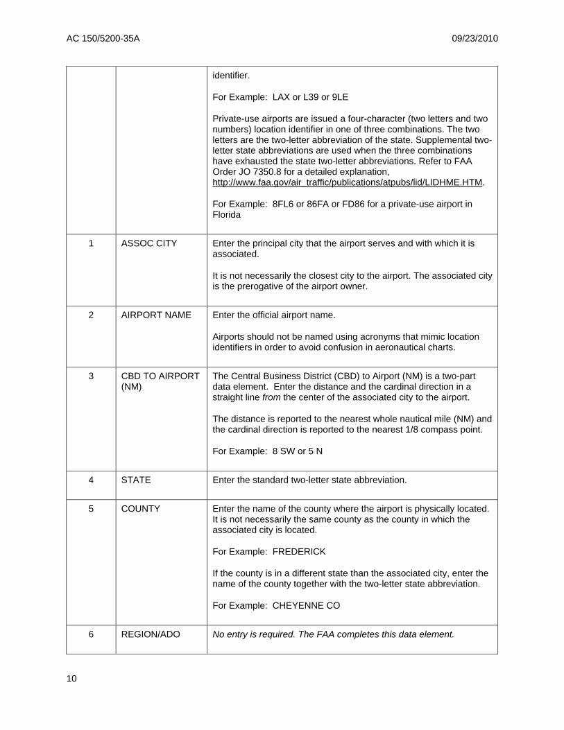
identifier.
For Example: LAX or L39 or 9LE
Private-use airports are issued a four-character (two letters and two numbers) location identifier in one of three combinations. The two letters are the two-letter abbreviation of the state. Supplemental two-letter state abbreviations are used when the three combinations have exhausted the state two-letter abbreviations. Refer to FAA Order JO 7350.8 for a detailed explanation, http://www.faa.gov/air_traffic/publications/atpubs/lid/LIDHME.HTM.
For Example: 8FL6 or 86FA or FD86 for a private-use airport in Florida
1 ASSOC CITY Enter the principal city that the airport serves and with which it is associated.
It is not necessarily the closest city to the airport. The associated city is the prerogative of the airport owner.
2 AIRPORT NAME Enter the official airport name.
Airports should not be named using acronyms that mimic location identifiers in order to avoid confusion in aeronautical charts.
3 CBD TO AIRPORT (NM)
The Central Business District (CBD) to Airport (NM) is a two-part data element. Enter the distance and the cardinal direction in a straight line from the center of the associated city to the airport.
The distance is reported to the nearest whole nautical mile (NM) and the cardinal direction is reported to the nearest 1/8 compass point.
For Example: 8 SW or 5 N
4 STATE Enter the standard two-letter state abbreviation.
5 COUNTY Enter the name of the county where the airport is physically located. It is not necessarily the same county as the county in which the associated city is located.
For Example: FREDERICK
If the county is in a different state than the associated city, enter the name of the county together with the two-letter state abbreviation.
For Example: CHEYENNE CO
6 REGION/ADO No entry is required. The FAA completes this data element.
10

09/23/2010 AC 150/5200-35A
This is three-letter code for the FAA Regional Office and the three-letter code for the FAA Airports District Office (ADO) [when there is one] separated by a slash.
For Example: ASO/ORL or ACE/NONE.
7 SECT AERO CHT No entry is required. The FAA completes this data element.
This is the VFR sectional chart on which the airport may be depicted.
8-9 RESERVED
GENERAL
10 OWNERSHIP Enter the two-letter abbreviation for the type of ownership of the airport using one of the entries below.
PU = Public (if the airport is owned by a public entity) PR = Private (if the airport is owned by an individual or a private
entity) MA = Military - Air Force MN = Military - Navy MR = Military - Army
11 OWNER If the airport is publicly owned, enter the full name of the public entity.
If the airport is privately owned, enter the full name of the owner or private entity.
If the airport owner leases the airport to another entity, enter the lessee’s name in this data element. Next enter a referenced remark in data element 110 explaining that this is the “Lessee” and then enter the owner’s name and address and telephone information in the referenced remark.
If the landing area is a seaplane base, enter the name of the owner of the property on which the shore facility is established.
If the airport is owned by the military, enter US Air Force, US Navy, US Army, etc.
12 ADDRESS Enter the mailing address of the owner or lessee identified in element 11.
13 PHONE NR Enter the phone number of the owner or lessee identified in data element 11.
11

AC 150/5200-35A 09/23/2010
14 MANAGER Enter the name of the airport manager or the person authorized by the controlling authority to exercise administrative control of the airport.
If this individual is not an airport manager, enter the name followed by the title.
For Example: John Doe, Mayor or Police Chief or City Clerk, etc.
If the airport is private use and there is no airport manager, re-enter the name of the owner or lessee identified in data element 11.
15 ADDRESS Enter the mailing address of the airport manager identified in data element 14.
If the airport is private use and there is no airport manager, re-enter the address of the owner or lessee identified in data element 11.
16 PHONE NR Enter the phone number of the airport manager.
If the airport is private use and there is no airport manager, re-enter the phone number of the owner or lessee identified in data element 11 or enter an alternate phone number for the owner or lessee.
17 ATTENDANCE SCHEDULE
Enter the months and days and hours (in local time) when there is an attendant or operator on duty to provide at least minimal services such as fuel sales, transportation, repairs, etc.
NOTE: The attendance schedule is not necessarily the hours of operation at the airport.
There are up to three lines available under the column headings.
Example 1: These are two most common entries for private-use airports:
MONTHS DAYS HOURS UNATTENDED or IRREGULAR
Example 2:
MONTHS DAYS HOURS JUN-AUG MON-FRI 0700-2100 SEP-MAY ALL 0800-DUSK
Example 3:
MONTHS DAYS HOURS ALL MON-FRI 0700-2100 ALL SAT DAWN-DUSK ALL SUN ON CALL
12

09/23/2010 AC 150/5200-35A
Enter specific months in the MONTHS column. Do not use entries such as 4 Months, seasons such as Spring or Fall, or month-day combinations such as April 15-May 30.
ON CALL requires a referenced remark in data element 110 listing a publishable phone number.
For Example: A017 FOR SERVICE SUNDAYS CALL XXX-XXX-XXXX.
18 AIRPORT USE Enter the use of the airport. There are only two entries.
PU = Public Use. A public-use airport is an airport available for use by the general public without a requirement for prior approval from the owner or operator.
The owners of public-use airports cannot impose operational restrictions on the use of the airport. Restrictions such as “prior permission required” or “use at your own risk” or “contact the airport manager prior to landing” are not permissible at public-use airports.
PR = Private Use. A private-use airport is an airport available for use by the owner only or by the owner and other persons authorized by the owner only.
Therefore, the owners of private-use airports do not have to reiterate in a remark in data element 110 that the airport is private use or that prior permission is required.
19 ARPT LAT See Airport Reference Point (ARP) in Chapter 1. Enter the estimated airport latitude in degrees, minutes, and seconds to one decimal place in NAD 83. (See Chapter 1 for an explanation of NAD 83.)
For Example: N 39º 25’ 30.3”
20 ARPT LONG See Airport Reference Point (ARP) in Chapter 1. Enter the estimated airport longitude in degrees, minutes, and seconds to one decimal place in NAD 83. (See Chapter 1 for explanation of NAD 83.)
For Example: W 077º 22’ 27.5”
21 ARPT ELEV Enter the airport elevation in whole feet above mean sea level (AMSL) measured along the centerline at the highest point of the airport’s usable runways.
22 ACREAGE Enter the total number of acres within the airport boundary.
13

AC 150/5200-35A 09/23/2010
23 RIGHT TRAFFIC Enter the runway number(s) for the runway(s) with a right-hand traffic pattern. A “yes” or “no” is an unacceptable entry in this data element.
For Example: RWY 18
Leave this data element blank if the traffic pattern to landing aircraft is the standard left-hand traffic pattern for all runway ends.
Right traffic is an airport airspace item, and accordingly, the FAA will not publish right traffic to a runway end until the FAA has performed an aeronautical study and the results of the study are favorable. Therefore, if the airport proponent desires a right-hand traffic pattern for a runway end, the airport proponent must file an FAA Form 7480-1, Notice of Landing Area Proposal, in order to initiate an aeronautical study.
24 NON-COMM LANDING
Enter Y if a landing fee is charged to non-commercial users of the airport.
Enter N if a landing fee is not charged to non-commercial users of the airport.
25 NPIAS/FEDERAL AGREEMENTS
No entry is required. The FAA completes this data element.
This data element is a list of codes that correspond to the federal agreements for airports in the FAA’s National Plan of Integrated Airport System (NPIAS).
26 PART 139 INDEX
This element is not required for civil private-use airports.
No entry is required. The FAA completes this data element.
This is a three-part data element showing the class and the ARFF Index operating certificate issued to an airport, the type of air carrier operation service, and the month and year the certificate was first issued.
27 - 29 RESERVED
RUNWAY DATA
30 RUNWAY IDENT This is the two-number identification (designation) of both ends of the runway and is derived from the magnetic compass headings of the runway ends. The runway end numbers are separated by a slash (/).
Enter the runway identification numbers of both ends separated by a slash. The runway identification number is reported in 10-degree increments by dropping the last zero.
For Example: 18/36 (the identification of a runway with a centerline
14

09/23/2010 AC 150/5200-35A
magnetic bearing of 180 degrees and 360 degrees)
For more detailed information, see AC 150/5340-1, Standards for Airport Markings.
RWY 18W/36W is the acceptable runway identification for a sealane.
The following suffixes can be used in conjunction with runway identification numbers even if the runway is not painted accordingly:
G = Glider Runway W = Water Sealane or Waterway U = Ultralight Runway
For Example: RWY 18W/36W, etc.
The following identification methods are also used: H1, H2, etc. is used for helipads, and B1, B2, etc. is used for balloon pads.
31 LENGTH Enter the total length of the runway to the nearest foot. A runway is a defined rectangular surface, and the runway length is the entire usable length of the runway. Displaced threshold lengths are included in the length of the runway.
32 WIDTH Enter the width of the runway to the nearest foot. For paved runways, enter the width that is full strength and usable for a runway.
A runway is a defined rectangular surface. If the width of the runway is uneven and varies, enter the narrowest width only.
33 SURF TYPE – COND
This is a two-part data element separated by a dash (-) comprised of the type of runway surface and the condition of the runway surface.
SURFACE TYPE: Enter the abbreviation for the runway surface type.
TURF = Grass or Sod or Turf CONC = Concrete or Portland Cement ASPH = Hot Mix, Bituminous Concrete Blacktop, Macadam,
Plant Mix, or Road Mix BRICK = Brick WOOD = Wood TRTD = Oiled, Soil Cement, Lime Stabilized, Asphalt or Coal-Tar
Seal Coat, or Paved Roof NOTE: TRTD cannot be reported alone. TRTD must follow a surface. For Example: ASPH-TRTD
GRVL = Gravel, Cinders, Crushed Rock, Coral, Shells, Slag, Laterite, or Shale
DIRT = Adobe, Bare, Bladed, Caliche, Clay, Dirt, Earth, Loam, Silt, or Soil
SNOW = Snow
15

AC 150/5200-35A 09/23/2010
ICE = Ice MATS = Pierced Steel Planking, Landing Mats, or Membrane
If the surface type is a combination of two surface types such as asphalt and turf (ASPH-TURF), enter the two surface types and then add a referenced remark in data element 110 explaining the exact dimensions of both surface types.
ASPH-CONC = Asphalt-Concrete ASPH-GRVL = Asphalt-Gravel ASPH-TRTD = Asphalt-Treated
For Example: A033 RWY 18/36 SOUTH 500 FEET ASPH, NORTH 2500 FEET TURF
Enter a hyphen (-) after the type of surface and then enter the condition of the runway surface.
CONDITION: Enter the abbreviation for the condition of the runway using one of the entries below:
E = Excellent G = Good F = Fair P = Poor L = Failed
For Example: CONC-P or ASPH-CONC-F or TURF-G
Use the following guidelines to determine whether the condition is “E”, “G”, “F”, “P”, or “L”:
E = Excellent Condition: New pavement or pavement with no cracks or a few hairline cracks.
G = Good Condition: Some cracking of the pavement. Cracks are generally spaced more than 50 feet apart. Less than 10% of the cracks and joints need sealing. There is minimal or slight raveling. There is no distortion, and the patches are in good condition.
F = Fair Condition: Some cracking and raveling. Cracks are generally spaced less than 50 feet apart. Joint and crack sealing is needed on 10% to 25% of the cracks and joints. There is isolated alligator cracking, the patches are in poor condition, and/or there are crack settlements up to 1 inch.
P = Poor Condition: Widespread, open, unsealed cracks and joints. There are cracks over ½-inch wide with raveling in 25% of the cracks. Cracks are generally spaced 5 to 50 feet apart with surface and slab spalling. Alligator cracking or patches are in poor condition and cover up to 20% of the surface or there is vegetation through the cracks and joints. If the condition is listed as poor, a referenced A033 remark is required.
L = Failed Condition: Widespread severe cracking and distortion
16
09/23/2010 AC 150/5200-35A
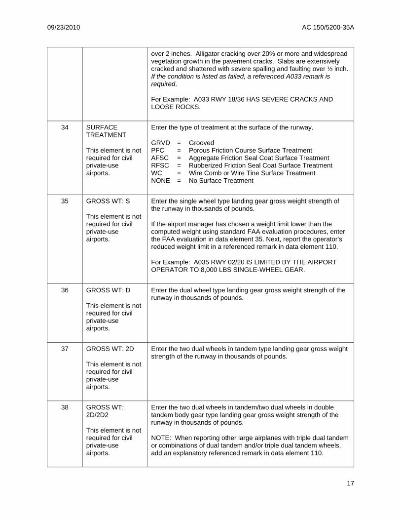
over 2 inches. Alligator cracking over 20% or more and widespread vegetation growth in the pavement cracks. Slabs are extensively cracked and shattered with severe spalling and faulting over ½ inch. If the condition is listed as failed, a referenced A033 remark is required.
For Example: A033 RWY 18/36 HAS SEVERE CRACKS AND LOOSE ROCKS.
34 SURFACE TREATMENT
This element is not required for civil private-use airports.
Enter the type of treatment at the surface of the runway.
GRVD = Grooved PFC = Porous Friction Course Surface Treatment AFSC = Aggregate Friction Seal Coat Surface Treatment RFSC = Rubberized Friction Seal Coat Surface Treatment WC = Wire Comb or Wire Tine Surface Treatment NONE = No Surface Treatment
35 GROSS WT: S
This element is not required for civil private-use airports.
Enter the single wheel type landing gear gross weight strength of the runway in thousands of pounds.
If the airport manager has chosen a weight limit lower than the computed weight using standard FAA evaluation procedures, enter the FAA evaluation in data element 35. Next, report the operator’s reduced weight limit in a referenced remark in data element 110.
For Example: A035 RWY 02/20 IS LIMITED BY THE AIRPORT OPERATOR TO 8,000 LBS SINGLE-WHEEL GEAR.
36 GROSS WT: D
This element is not required for civil private-use airports.
Enter the dual wheel type landing gear gross weight strength of the runway in thousands of pounds.
37 GROSS WT: 2D
This element is not required for civil private-use airports.
Enter the two dual wheels in tandem type landing gear gross weight strength of the runway in thousands of pounds.
38 GROSS WT: 2D/2D2
This element is not required for civil private-use airports.
Enter the two dual wheels in tandem/two dual wheels in double tandem body gear type landing gear gross weight strength of the runway in thousands of pounds.
NOTE: When reporting other large airplanes with triple dual tandem or combinations of dual tandem and/or triple dual tandem wheels, add an explanatory referenced remark in data element 110.
17

AC 150/5200-35A 09/23/2010
For Example: A038 RWY 02/20 THE TRIPLE DUAL TANDEM LANDING GEAR GROSS WEIGHT STRENGTH IS 700,000 POUNDS.
39 PCN
This element is not required for civil private-use airports.
The ACN/PCN System is the ICAO standard method of reporting pavement strength for pavements with bearing strengths greater than 12,500 pounds.
The Pavement Classification Number (PCN) is established by an engineering assessment of the runway (NOT to be confused with PCI). The PCN is for use in conjunction with an Aircraft Classification Number (ACN).
PCN is comprised of 5 entry fields:
PAVEMENT CLASS: Numerical value up to 3-digits PAVEMENT TYPE: R-Rigid or F-Flexible SUBGRADE STRENGTH: A-High, B-Medium, C-Low, or D-Ultra-
Low TIRE PRESSURE LIMIT: W-High (No Pressure Limit), X-Medium
(Limit to 218 PSI), Y-Low (Limit to 145 PSI), or Z-Very Low (Limit to 73 PSI)
RATING METHOD: T-Technical Evaluation or U-By Experience
For Example: 80/R/B/W/T (represents Pavement Class=80, Pavement Type=R-Rigid, Subgrade Strength=B-Medium, Tire Pressure Limit=W-High (No Limit), and Rating Method=T-Technical Evaluation)
LIGHTING/APPROACH AIDS
40 EDGE INTENSITY Enter the type of runway edge lighting system.
HIGH = High Intensity Runway Lights MED = Medium Intensity Runway Lights LOW = Low Intensity Runway Lights PERIMETER = Perimeter Lights (for helipads) FLOOD = Flood Lights (for helipads) NSTD = Non-Standard
If the runway edge lights do not meet FAA advisory circular standards and are non-standard due to improper spacing or color or placement, enter NSTD in data element 40 and then add an explanatory referenced remark in data element 110.
For Example: A040 RWY 03/21 NSTD LIRL DUE TO THLD LIGHTS ALL GREEN.
If the runway edge lights do not meet FAA advisory circular standards and are non-standard because only part of the runway is lighted, enter NSTD in data element 40 and then add an explanatory referenced remark in data element 110.
18
09/23/2010 AC 150/5200-35A
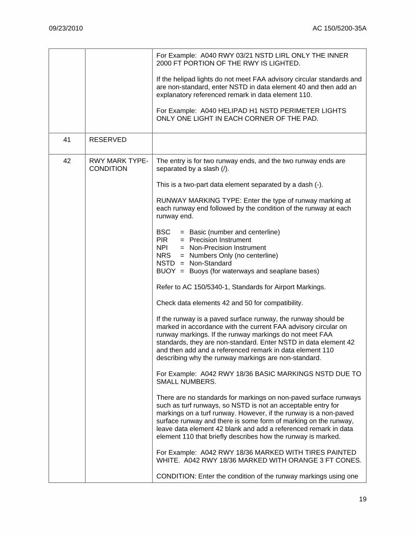
For Example: A040 RWY 03/21 NSTD LIRL ONLY THE INNER 2000 FT PORTION OF THE RWY IS LIGHTED.
If the helipad lights do not meet FAA advisory circular standards and are non-standard, enter NSTD in data element 40 and then add an explanatory referenced remark in data element 110.
For Example: A040 HELIPAD H1 NSTD PERIMETER LIGHTS ONLY ONE LIGHT IN EACH CORNER OF THE PAD.
41 RESERVED
42 RWY MARK TYPE-CONDITION
The entry is for two runway ends, and the two runway ends are separated by a slash (/).
This is a two-part data element separated by a dash (-).
RUNWAY MARKING TYPE: Enter the type of runway marking at each runway end followed by the condition of the runway at each runway end.
BSC = Basic (number and centerline) PIR = Precision Instrument NPI = Non-Precision Instrument NRS = Numbers Only (no centerline) NSTD = Non-Standard BUOY = Buoys (for waterways and seaplane bases)
Refer to AC 150/5340-1, Standards for Airport Markings.
Check data elements 42 and 50 for compatibility.
If the runway is a paved surface runway, the runway should be marked in accordance with the current FAA advisory circular on runway markings. If the runway markings do not meet FAA standards, they are non-standard. Enter NSTD in data element 42 and then add and a referenced remark in data element 110 describing why the runway markings are non-standard.
For Example: A042 RWY 18/36 BASIC MARKINGS NSTD DUE TO SMALL NUMBERS.
There are no standards for markings on non-paved surface runways such as turf runways, so NSTD is not an acceptable entry for markings on a turf runway. However, if the runway is a non-paved surface runway and there is some form of marking on the runway, leave data element 42 blank and add a referenced remark in data element 110 that briefly describes how the runway is marked.
For Example: A042 RWY 18/36 MARKED WITH TIRES PAINTED WHITE. A042 RWY 18/36 MARKED WITH ORANGE 3 FT CONES.
CONDITION: Enter the condition of the runway markings using one
19

AC 150/5200-35A 09/23/2010
of the entries below:
G = Good F = Fair P = Poor
If the runway marking condition is poor, an explanatory referenced remark is required in data element 110.
For Example: A042 RWY 18/36 MARKINGS FADED.
43 VGSI
This element is not required for civil private-use airports.
The entry is for two runway ends, and the two runway ends are separated by a slash (/).
This is the type of visual glideslope indicator (VGSI) equipment that is available at a runway end to a pilot on final approach.
Enter the type of equipment and, if applicable, the numbers of boxes for the runway end approach at which it is located. The standard VGSI entries are listed below and are also listed in the directory legend of any Airport/Facility Directory.
NOTE: Be aware that there is a difference between the entry in element 43 and in an A081 referenced remark. Data element 43 contains the abbreviated codes V2L or TRIL, but in the referenced remark, it must be written as a VASI or TRCV.
VGSI ENTRIES
S2L = 2-box Simplified Abbreviated Visual Approach Slope Indicator (SAVASI) on the Left side of the runway
S2R = 2-box Simplified Abbreviated Visual Approach Slope Indicator (SAVASI) on the Right side of the runway
V2L = 2-box Visual Approach Slope Indicator (VASI) on the Left side of the runway
V2R = 2-box Visual Approach Slope Indicator (VASI) on the Right side of the runway
V4L = 4-box Visual Approach Slope Indicator (VASI) on the Left Side of the runway
V4R = 4-box Visual Approach Slope Indicator (VASI) on the Right side of the runway
V6L = 6-box Visual Approach Slope Indicator (VASI) on the Left side of the runway
V6R = 6-box Visual Approach Slope Indicator (VASI) on the Right side of the runway
V12 = 12-box Visual Approach Slope Indicator (VASI) on both sides of the runway
V16 = 16-box Visual Approach Slope Indicator (VASI) on both sides of the runway
P2L = 2-box Precision Approach Path Indicator (PAPI) on the Left side of the runway
P2R = 2-box Precision Approach Path Indicator (PAPI) on the Right side of the runway
P4L = 4-box Precision Approach Path Indicator (PAPI) on the Left Side of the Runway.
20

09/23/2010 AC 150/5200-35A
P4R = 4-box Precision Approach Path Indicator (PAPI) on the Right side of the runway
TRIL = Tri-Color Visual Approach Slope Indicator (TRCV) on the Left side of the runway, normally a single light unit projecting three colors
TRIR = Tri-Color Visual Approach Slope Indicator (TRCV) on the Right side of the runway, normally a single light unit projecting three colors
PSIL = Pulsating/Steady Burning Visual Approach Slope Indicator (PVASI) on the Left side of the runway, normally a single light unit projecting two colors
PSIR = Pulsating/Steady Burning Visual Approach Slope Indicator (PVASI) on the Right side of the runway, normally a single light unit projecting two colors
PNIL = A System of Panels (APAP) used for alignment of an approach path, which may or may not be lighted, on the Left side of the runway
PNIR = A System of Panels (APAP) used for alignment of an approach path, which may or may not be lighted, on the Right Side of the runway
PVT = A Privately Owned, for Private Use Only, approach slope indicator light system installed on a public-use airport
NSTD = Any visual approach slope indicator system not approved by the FAA. Enter NSTD when a non-standard system exists. Enter a referenced remark in data element 110 describing the NSTD VGSI
44 THR CROSSING HGT
This element is not required for civil private-use airports.
The entry is for two runway ends, and the two runway ends are separated by a slash (/).
Enter the threshold crossing height of the visual glideslope indicator equipment at each runway end to the nearest whole foot.
Obtain the information from the airport manager, the Airport Layout Plan (ALP), or the appropriate FAA office if installed with Federal funds.
45 VISUAL GLIDE ANGLE
This element is not required for civil private-use airports.
The entry is for two runway ends, and the two runway ends are separated by a slash (/).
Enter the glide angle of the visual glideslope indicator equipment installed at each runway end to the hundredths of a degree.
For Example: 3.00º or 3.25º
Obtain this information from the airport manager, the ALP, or the appropriate FAA office if installed with Federal funds.
46 CNTRLN-TDZ
This element is not required for civil
The entry is for two runway ends, and the two runway ends are separated by a slash (/).
This is a two-part data element separated by a dash (-) for the
21

AC 150/5200-35A 09/23/2010
private-use airports.
centerline lights and the touchdown zone lights at each runway end.
Enter Y if the runway has centerline lights or N for none.
Enter Y if the runway has touchdown zone lights or N for none.
For Example: Y-N/Y-Y
47 RVR-RVV
This element is not required for civil private-use airports.
The entry is for two runway ends, and the two runway ends are separated by a slash (/).
This is a two-part data element separated by a dash (-) for the runway visual range and the runway visibility value installed at each runway end.
Enter one or more of the following letter codes to indicate the runway visual range equipment installed at the runway end:
T = Touchdown M = Mid-Field R = Roll Out N = No RVR Available
Then enter a hyphen (-)
Then enter a Y or N to indicate if runway visibility value equipment is installed.
For Example: TMR-N/TMR-N; N-Y/N-Y
48 REIL
This element is not required for civil private-use airports.
The entry is for two runway ends, and the two runway ends are separated by a slash (/).
Enter Y for yes if the runway end has runway end identifier lights installed.
Enter N for no if the runway end does not have runway end identifier lights installed.
For Example: Y/N
49 APCH LGTS
This element is not required for civil private-use airports.
The entry is for two runway ends, and the two runway ends are separated by a slash (/).
Enter the particular type of approach lighting system that is installed at each runway end.
ALSF = 3000-Foot High Intensity Approach System With Centerline Sequence Flashers
ALSF1 = Standard 2,400-Foot High Intensity Approach System With Sequenced Flashers - Category I Configuration
ALSF2 = Standard 2,400-Foot High Intensity Approach System
22

09/23/2010 AC 150/5200-35A
With Sequenced Flashers - Category II or III Configuration
MALS = 1,400-Foot Medium Intensity Approach Light System MALSF = 1,400-Foot Medium Intensity Approach Light System
With Sequenced Flasher Lights MALSR = 2,400-Foot Medium Intensity Approach Light System
With Runway Alignment Indicator Lights SSALS = Simplified Short Approach Lighting System SSALF = Simplified Short Approach Lighting System With
Runway Sequenced Flasher Lights SSALR = Simplified Short Approach Lighting System With
Runway Alignment Indicator Lights ODALS = Omni-Directional Approach Lighting System. Do not
show REIL in addition to ODALS because the REIL are part of this system.
LDIN = Lead-In Light System NSTD = All Others are Non-Standard NONE = No Approach Lighting System is Available
Also see the directory legend in the Airport/Facility Directory.
OBSTRUCTION DATA The entry is for two runway ends, and the two runway ends are separated by a slash (/). Enter the runway category defined by Part 77 for the most precise EXISTING approach to each runway end. See http://www.ngs.noaa.gov/AERO/oisspec.html.
ENTER FOR PRIMARY SURFACE
WIDTH
APPROACH SURFACE
SLOPE
A(V) Utility runway with a visual approach
250 feet 20:1
B(V) Other than utility runway with a visual approach.
500 feet 20:1
A(NP) Utility runway with a non-precision approach
500 feet 20:1
C Other than utility runway with a non-precision approach having visibility minimums greater than ¾ mile
500 feet 34:1
50 PART 77 CATEGORY
This element is not required for heliports.
D Other than utility runway with a non-precision approach having visibility minimums less than or equal to ¾ mile
1,000 feet 34:1
23

AC 150/5200-35A 09/23/2010
PIR Precision Instrument Runway
1,000 feet 50:1
PART 77 CATEGORY NOTES UTILITY RUNWAY = a runway that is constructed for and intended to be used by propeller driven aircraft of 12,500 pounds maximum gross weight and less.
OTHER THAN UTILITY RUNWAY = a runway that is intended to be used by propeller driven aircraft with a maximum gross weight greater than 12,500 pounds and/or jet aircraft of any gross weight.
NOTE: After the “utility” or “other than utility” category is determined for that runway, look at the instrument approach procedures for the type of approach and visibility minimums. This will determine the correct Part 77 Category for that particular runway.
VISUAL RUNWAY = a runway using visual approach procedures, with no straight-in instrument approach procedures and no instrument designation.
NON-PRECISION INSTRUMENT RUNWAY = a runway having an existing instrument approach procedure utilizing air navigation facilities with only horizontal guidance, or area type navigation equipment, for which a straight-in non-precision instrument approach procedure has been approved, or planned, and for which no precision approach facilities are planned or indicated on an FAA planning document or military service military airport planning document.
PRECISION INSTRUMENT RUNWAY = a runway with an existing instrument approach procedure utilizing an instrument landing system (ILS) or a Precision Approach Radar (PAR).
APPROACH SURFACE = a surface longitudinally centered on the extended runway centerline and extending outward and upward from each end of the primary surface. An approach surface is applied to each end of each runway based upon the type of approach available for that runway end.
51 DSPLCD THLD The entry is for two runway ends, and the two runway ends are separated by a slash (/).
Enter the length of the displaced threshold at a runway end in whole feet.
DISPLACED THRESHOLD MARKINGS FOR RUNWAYS WITH A PAVED SURFACE: When a threshold is displaced, the markings at a displaced portion of the runway should be marked in accordance with the current FAA advisory circular on runway markings. If not, enter an explanatory referenced remark in data element 110.
For Example: A051 RWY 03 DSPLCD THLD MARKINGS NSTD
24

09/23/2010 AC 150/5200-35A
YELLOW.
DISPLACED THRESHOLD MARKINGS FOR RUNWAYS WITH A NON-PAVED SURFACE: Describe any form of markers used at the displaced threshold of a turf or gravel runway in an explanatory referenced remark in data element 110.
For Example: A051 RWY 03 DSPLCD THLD MARKED WITH ORANGE CONES.
52 CTLG OBSTN The entry is for two runway ends, and the two runway ends are separated by a slash (/).
Enter the obstruction within the boundaries of the approach surface that controls the obstruction clearance slope to a runway end (not the displaced threshold). The approach surface is defined in Part 77.
For paved runways, the approach surface starts 200 feet from the runway end, so the controlling obstruction must be at least 200 feet from the runway threshold. Nothing located in the primary surface (0-199 feet) can be listed as the controlling obstruction.
For non-paved surface (unpaved) runways, the approach surface starts at the actual runway threshold (not 200 feet from the runway threshold).
If there is an entry in data element 52, then entries are required in data elements 53 through 55 for private-use airports and 53 through 57 for public-use airports.
The following standard entries can be used:
ACFT = Aircraft ANT = Antenna, Antenna Mast on building, Radio/Television BERM = Berm, Dike, Levee, Riverbank, etc. BLDG = House, Factory, Church, Hangar, etc. BOAT = Boat or Ship that normally traverse the lake, river,
canal, channel, etc. BRDG = Bridge, Overpass, etc. BRUSH = Brush, Shrubs, Hedge, etc. FENCE = Fence GND = Ground or Rising Terrain HILL = Hill, Sand Dunes, Gravel or Rock Pile, Knoll, Cliff,
Canyon, Wall, Mountain, Butte, etc. PLINE = Power Line, Telephone Lines, etc. POLE = Power Pole, Telephone Pole, Light Pole, Flag Pole,
etc. ROAD = Private Road, Public Road, or Interstate Highway RR = Railroad SIGN = Sign, Billboard, etc. STACK = Smoke Stack, Chimney, etc. TANK = Storage Tank TOWER = Tower, Beacon, Derrick, Drilling Rig, Microwave Tower,
25

AC 150/5200-35A 09/23/2010
Radio or TV Transmitter, Windmill, Water Tower, etc. TREE = Tree TREES = Forest, Orchard, Grove, etc. NONE = If no object penetrates the applicable approach surface
as defined in Part 77
All obstructions should be covered by one of the above classifications. However, if an unusual obstruction is encountered, describe the obstruction in a reference remark in data element 110.
Navigational aids and lighting apparatus associated with the operation of an airport are fixed by function and will NOT be reported as an obstruction.
53 OBSTN MARKED/LGTD
The entry is for two runway ends, and the two runway ends are separated by a slash (/).
Indicate whether or not the controlling obstruction in data element 52 is marked and/or lighted by entering one or more of the following:
M = Marked L = Lighted ML = Both Marked and Lighted NONE = If the controlling obstruction is neither marked nor lighted
54 HGT ABOVE RWY END
The entry is for two runway ends, and the two runway ends are separated by a slash (/).
Enter the height of the controlling obstruction above the runway end. Enter the “effective height” of an object if it is a road or railroad. The effective height is the sum of the actual object height above the runway end plus the penalty height imposed by Part 77.
Private Road = 10 feet or the height of the highest mobile object that would normally traverse the road, whichever is greater
Non-Interstate Road = 15 feet Interstate Highway = 17 feet Railroad = 23 feet Waterway = The height of the highest mobile object that
would normally traverse the waterway
55 DIST FROM RWY END
The entry is for two runway ends, and the two runway ends are separated by a slash (/).
Enter the distance in feet along the runway centerline extended from the runway threshold (not the displaced threshold) to the controlling obstruction. Measure the distance horizontally along the extended runway centerline (not a slant distance) to the point abeam the obstruction.
26

09/23/2010 AC 150/5200-35A
56 CNTRLN OFFSET
This element is not required for civil private-use airports.
The entry is for two runway ends, and the two runway ends are separated by a slash (/).
This data element is calculated based on what a pilot sees as the pilot is flying an approach to a runway end. This is a two-part data element.
Enter the distance in feet that the controlling obstruction is located away from the extended runway centerline. Measure the distance horizontally on a line perpendicular to the extended runway centerline. Next enter whether the obstruction is right (R) or left (L) of the centerline as viewed by a pilot on final approach.
If the obstruction is a single obstruction and it is located directly on the centerline, enter the number zero followed by the letter B (e.g. 0B).
If the obstruction spans both sides of the extended centerline, such as a row of trees, a road, or a power line, enter the distance right and left of the centerline followed by the letters L/R (e.g. 100L/R).
57 OBST CLNC SLOPE
This element is not required for civil private-use airports.
The entry is for two runway ends, and the two runway ends are separated by a slash (/).
Enter the obstruction clearance slope of the controlling obstruction identified in data element 52 using a ratio to indicate the clearance available to aircraft approaching that runway end. Slope ratios range from 1:1 to 50:1. Entries are also required in data elements 52, 54, 55 and 56.
However, if there are no objects penetrating the Part 77 Category approach slope, then the runway approach is clear and there are no obstructions. Enter either 20:1 or 34:1 or 50:1, depending on the Part 77 Category approach to the runway end and no entries are required in data elements 52 through 56.
For paved surface runways, the obstruction clearance slope begins at the end of the primary surface, which ends 200 feet beyond the end of the runway. Measure the obstruction clearance slope from the end of the primary surface whether or not that runway threshold has been displaced.
For non-paved surface (unpaved) runways, the obstruction clearance slope also begins at the end of the primary surface, so it is important to note that the primary surface ends at the runway end and not 200 feet beyond the end of the runway. Measure the obstruction clearance slope from the end of the primary surface whether or not that runway threshold has been displaced.
For paved/unpaved combination runways, each end of the primary surface coincides with the corresponding end of the runway.
PAVED SURFACE RUNWAYS:
27

AC 150/5200-35A 09/23/2010
Approach Ratio Calculation
The distance from the runway end (data element 55) minus 200 feet, divided by the height above the runway end (data element 54).
NON-PAVED SURFACE (UNPAVED) RUNWAYS: Approach Ratio Calculation
The distance from runway end (data element 55) divided by the height above the runway end (data element 54). [Hence there is no need to subtract 200 feet.]
Remember to always round down when the division of the distance by the height does not result in a whole number. Therefore, a slope of 19.9 is rounded down for safety to 19.
APPROACH SLOPE FOR DISPLACED THRESHOLDS: If an obstruction penetrates the approach slope to the displaced threshold and the obstruction is not the same one identified as the controlling obstruction to the runway end, it should be described in a referenced remark in data element 110. All heights and distances are with respect to the displaced threshold.
For Example: A057 RWY 09 APCH SLOPE 25:1 DUE TO 24 FT TREE 600 FT FROM THE DSPLCD THLD.
58 CLOSE-IN OBSTN
This element is not required for civil private-use airports.
The entry is for two runway ends, and the two runway ends are separated by a slash (/).
This data element is for hard surface runways only. There can never be a close-in obstruction at the end of an unpaved runway.
Enter Y if there is an obstruction in the approach within the first 200 feet of the runway end. In addition, an explanatory referenced remark is required in data element 110, identifying the obstruction, its height above the runway end, its distance from the runway end, and the centerline offset left or right to a pilot on final approach.
For Example: A058 RWY 18 HAS 4 FT HILL 150 FT FROM THE RWY END AND 100 FT R.
59 RESERVED
DECLARED DISTANCES Only FAA airport inspectors or FAA Region or Airport District Office personnel can provide the declared distances data elements.
60 TAKE OFF RUN AVBL (TORA)
This element is not required for civil
Enter the takeoff run available. It is the runway length declared available and suitable for the ground run of an airplane taking off.
28
09/23/2010 AC 150/5200-35A
private-use airports.
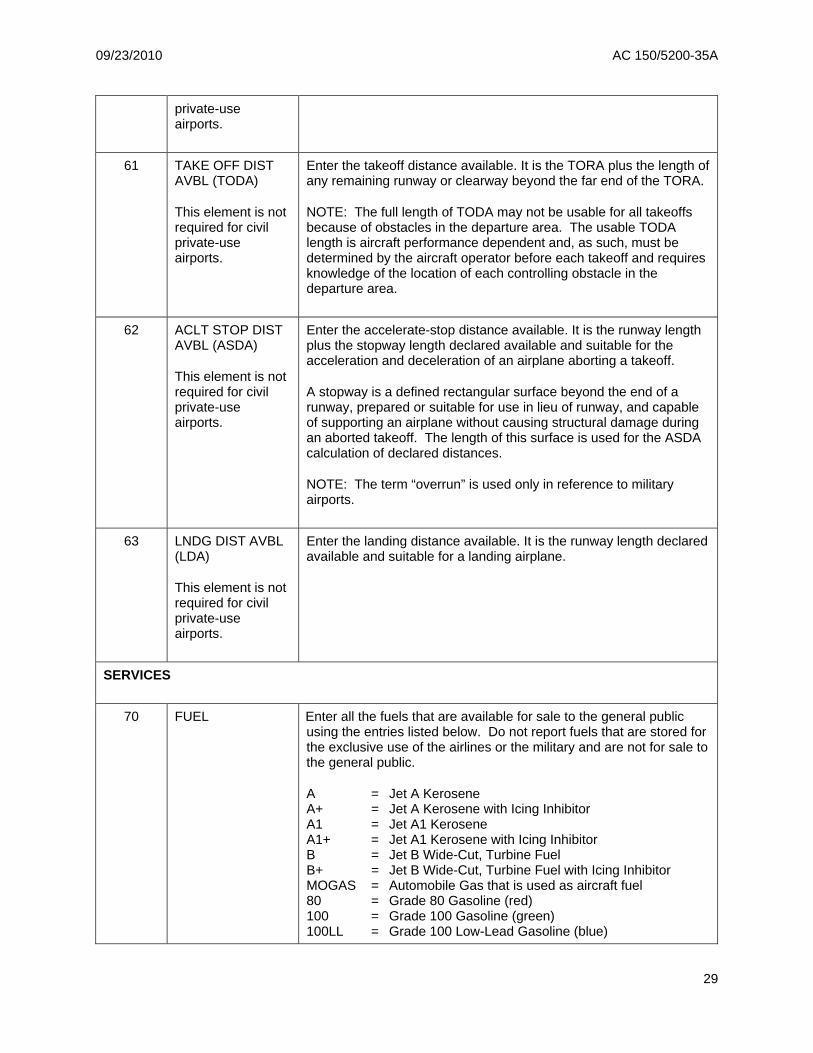
61 TAKE OFF DIST AVBL (TODA)
This element is not required for civil private-use airports.
Enter the takeoff distance available. It is the TORA plus the length of any remaining runway or clearway beyond the far end of the TORA.
NOTE: The full length of TODA may not be usable for all takeoffs because of obstacles in the departure area. The usable TODA length is aircraft performance dependent and, as such, must be determined by the aircraft operator before each takeoff and requires knowledge of the location of each controlling obstacle in the departure area.
62 ACLT STOP DIST AVBL (ASDA)
This element is not required for civil private-use airports.
Enter the accelerate-stop distance available. It is the runway length plus the stopway length declared available and suitable for the acceleration and deceleration of an airplane aborting a takeoff.
A stopway is a defined rectangular surface beyond the end of a runway, prepared or suitable for use in lieu of runway, and capable of supporting an airplane without causing structural damage during an aborted takeoff. The length of this surface is used for the ASDA calculation of declared distances.
NOTE: The term “overrun” is used only in reference to military airports.
63 LNDG DIST AVBL (LDA)
This element is not required for civil private-use airports.
Enter the landing distance available. It is the runway length declared available and suitable for a landing airplane.
SERVICES
70 FUEL Enter all the fuels that are available for sale to the general public using the entries listed below. Do not report fuels that are stored for the exclusive use of the airlines or the military and are not for sale to the general public.
A = Jet A Kerosene A+ = Jet A Kerosene with Icing Inhibitor A1 = Jet A1 Kerosene A1+ = Jet A1 Kerosene with Icing Inhibitor B = Jet B Wide-Cut, Turbine Fuel B+ = Jet B Wide-Cut, Turbine Fuel with Icing Inhibitor MOGAS = Automobile Gas that is used as aircraft fuel 80 = Grade 80 Gasoline (red) 100 = Grade 100 Gasoline (green) 100LL = Grade 100 Low-Lead Gasoline (blue)
29

AC 150/5200-35A 09/23/2010
115 = Grade 115 Gasoline (purple)
71 AIRFRAME RPRS
This element is not required for civil private-use airports.
Enter the type of airframe repair that is available at the airport. There are two entries: MAJOR or MINOR.
Minor airframe repairs are the repairs that can be performed by an Airframe and Powerplant mechanic (A&P).
Major airframe repairs require the maintenance technician performing or inspecting the work to have the additional qualification as an Airworthiness Inspector (IA).
72 PWR PLANT RPRS
This element is not required for civil private-use airports.
Enter the type of power plant repair that is available at the airport. There are two entries: MAJOR or MINOR.
MINOR powerplant repairs are the repairs that can be performed by an Airframe and Powerplant mechanic (A&P).
MAJOR powerplant repairs require the maintenance technician performing or inspecting the work to have the additional qualification as an Airworthiness Inspector (IA).
73 BOTTLE OXYGEN
This element is not required for civil private-use airports.
Enter the type of bottle oxygen available for sale to the general public. Do not report replacement bottles that are stored by the airlines or the military.
Enter HIGH to indicate that high-pressure oxygen replacement bottles are available at the airport for sale to the general public.
Enter LOW to indicate that low-pressure oxygen replacement bottles are available at the airport for sale to the general public.
Enter HIGH/LOW when both HIGH and LOW pressure oxygen replacement bottles are available at the airport for sale to the general public.
HIGH = 1,800–2,200 Pounds Per Square Inch (psi) LOW = 400–450 Pounds Per Square Inch (psi) HIGH/LOW = High and Low bottle oxygen are both available
74 BULK OXYGEN
This element is not required for civil private-use airports.
Enter the type of bulk storage oxygen that is available for sale to the general public. Do not report bulk bottles that are stored by the airlines or the military.
Enter HIGH to indicate that bulk storage high-pressure oxygen is available at the airport for sale to the general public.
Enter LOW to indicate that bulk storage low-pressure oxygen is available at the airport for sale to the general public.
Enter HIGH/LOW when both HIGH and LOW pressure bulk storage
30

09/23/2010 AC 150/5200-35A
oxygen are available at the airport for sale to the general public.
HIGH = Greater than 1,500 Pounds Per Square Inch (psi) LOW = Less than 1,500 Pounds Per Square Inch (psi) HIGH/LOW = High and Low bulk oxygen are both available
75 TSNT STORAGE
This element is not required for civil private-use airports.
Enter the types of transient aircraft storage available at the airport. Tie downs must have a referenced remark if the pilot needs to supply his own ropes.
HGR = Hangar TIE = Tie Downs BUOY = Buoy (for Seaplane Bases Only)
76 OTHER SERVICES
This element is not required for civil private use airports
Enter other types of services available at the airport.
AFRT = Air Freight GLD = Glider AGRI = Crop Dusting INSTR = Flight Instruction AMB = Air Ambulance PAJA = Parachute Jumping AVNCS = Avionics RNTL = Aircraft Rental BCHGR = Beaching Gear SALES = Aircraft Dealer CARGO = Cargo SURV = Aerial Surveying CHTR = Charter TOW = Glider Towing
NOTE: The FAA cannot advertise services and accordingly will not print services such as rental car info or hotel info, so please do not include that kind of information.
77 - 79 RESERVED
FACILITIES
80 ARPT BCN Enter the two-letter or three-letter abbreviation for the type of airport beacon (also known as the rotating beacon) at the airport. The colors indicate the type of landing area.
C-G = Clear-Green (Civil airport) C-Y = Clear-Yellow (Seaplane Base) C-G-Y = Clear-Green-Yellow (Heliport) S-C-G = Split-Clear-Green (Military airport)
81 ARPT LGT SCHEDULE
This data element refers to the schedule of the airport beacon. In addition, it also refers to the schedule of any other lighting aids that are also on the same schedule as the airport beacon.
Enter the lighting schedule of the airport beacon.
DUSK-DAWN = Dusk to Dawn SS-SR = Sunset to Sunrise RDO-CTL = Radio Controlled
31

AC 150/5200-35A 09/23/2010
RDO-REQ = Radio Request
PHONE-REQ = Phone Request DUSK-2300 = Dusk to Specific Hour
RDO-CTL requires an explanatory referenced remark in data element 110 that includes the Unicom frequency or the CTAF frequency.
For Example: A081 ACTVT LIRL RY 18/36 AND VASI RWY 18 – 122.7.
PHONE-REQ requires an explanatory referenced remark in data element 110.
For Example: A081 FOR LIRL RWY 18/36 CALL XXX-XXX-XXXX.
82 UNICOM Enter the frequency issued by the FCC to operate an aeronautical advisory station at the airport.
At any airport, the Unicom frequencies are: 122.7, 122.725, 122.8, 122.950, 122.975, 123.0, 123.050 and 123.075.
NOTE: Frequency 122.9 is not a Unicom frequency; it is a multicom frequency, and an FCC license is not required.
NOTE: The FCC issues only one Unicom frequency per airport.
83 WIND INDICATOR Enter Y for yes or N for no to indicate the existence of a wind indicator at the airport.
If the airport has a wind indicator and it is lighted, place a dash (-) after the Y and then place an L for lighted.
For Example: Y-L
84 SEGMENTED CIRCLE
Enter Y for yes or N for no to indicate the existence of a segmented circle at the airport.
85 CONTROL TWR No entry is required. The FAA completes this data element.
Airport Traffic Control Tower
86 FSS No entry is required. The FAA completes this data element.
Flight Service Station
87 FSS ON ARPT No entry is required. The FAA completes this data element.
32

09/23/2010 AC 150/5200-35A
FSS on airport
88 FSS PHONE NR No entry is required. The FAA completes this data element.
FSS phone number
89 TOLL FREE NR No entry is required. The FAA completes this data element.
FSS toll free number.
BASED AIRCRAFT The number of operational aircraft normally based at the airport for each category below.
90 SINGLE ENGINE Enter the number of operational single engine propeller driven aircraft either reciprocal engine or turboprop normally based at the airport.
91 MULTI-ENGINE Enter the number of operational multi-engine propeller-driven aircraft either reciprocal engine or turboprop normally based at the airport.
92 JET Enter the number of operational jet aircraft normally based at the airport (do not include turboprop aircraft).
TOTAL The total of element numbers 90 and 91 and 92 are automatically calculated.
93 HELICOPTERS Enter the number of operational helicopters normally based at the airport.
94 GLIDERS Enter the number of operational gliders normally based at the airport.
95 MILITARY Enter the number of operational military aircraft normally based at the airport.
96 ULTRA-LIGHT Enter the number of operational ultralight aircraft normally based at the airport.
97-99 RESERVED
OPERATIONS 12-month count of operations. An operation is either a takeoff or a landing. Obtain the best estimate from the airport manager, the pilot registration book, or the ATCT.
33

AC 150/5200-35A 09/23/2010
100 AIR CARRIER
This element is not required for civil private-use airports.
Enter the number of scheduled and unscheduled air carrier operations for aircraft with 60 or more passenger seats.
101 COMMUTER
This element is not required for civil private-use airports.
Leave this data element blank.
When commuter operations exist at an airport, the number of operations is no longer entered in this data element. Instead, it is added to and included with the number of air taxi operations in data element 102. A commuter operation includes all scheduled and unscheduled air carrier operations for aircraft with less than 60 passenger seats (see data element 102, air taxi).
102 AIR TAXI
This element is not required for civil private-use airports.
Enter the number of scheduled or unscheduled air carrier and air taxi operations for aircraft with less than 60 passenger seats.
103 GA LOCAL
This element is not required for civil private-use airports.
Enter the number of general aviation local operations at the airport. A local operation is defined as an operation within the airport traffic pattern or the aircraft is known to be from within 20 miles of the airport.
104 GA ITNRNT
This element is not required for civil private-use airports.
Enter the number of general aviation itinerant operations at the airport. An itinerant operation is defined as an operation that is other than a local operation.
105 MILITARY
This element is not required for civil private-use airports.
Enter the number of military operations at the airport.
No Number
OPERATIONS FOR 12 MOS ENDING
Enter the operations ending date in a month/day/year format for the 12-months period in which the operations were counted. The operations ending date may not necessarily be the same date as the date of the airport inspection.
34

09/23/2010 AC 150/5200-35A
106-109 RESERVED
110 REMARKS Enter all general remarks and referenced remarks in this section.
Ensure that all remarks are worded as clearly as possible to avoid pilot confusion.
111 INSPECTOR (Form 5010-3)
or
OWNER-MANAGER SIGNATURE (Form 5010-5)
Form 5010-3, public-use airports: Enter within the parenthesis ( ) that follows INSPECTOR, the one-letter abbreviation for the type of airport inspector that inspected the airport, and then place your signature and organization here.
F = FAA Inspected S = State Inspected C = Contractor Inspected N = Not Inspected
Form 5010-5, private-use airports: Proponents of new private-use airports, place your signature next to OWNER/MANAGER SIGNATURE.
112 DATE LAST INSPECTED
This element is not required for civil private-use airports.
Enter the date that the airport inspector completed the physical inspection of a newly constructed or newly reported civil public-use airport using Form 5010-3.
113 LAST INFO REQ (Form 5010-3)
or DATE (Form 5010-5)
Form 5010-3, public-use airports: Leave this date blank.
Form 5010-5, private-use airports: Enter the date that the proponent completed the Form 5010-5.
35

AC 150/5200-35A 09/23/2010
36
This page intentionally left blank.

09/23/2010 AC 150/5200-35A
Appendix A. FAA Form 5010-3
FAA FORM 5010-3 is used to provide the initial physical inspection report on newly constructed or newly reported civil public-use airports. A fillable version of Form 5010-3 is available at http://www.faa.gov/forms/.
37

AC 150/5200-35A 09/23/2010
38

09/23/2010 AC 150/5200-35A
Appendix B. FAA Form 5010-5
FAA FORM 5010-5 is used to provide the initial report on newly constructed or newly reported civil private-use airports. A fillable version of Form 5010-5 is available at http://www.faa.gov/forms/.
39

AC 150/5200-35A 09/23/2010
40

09/23/2010 AC 150/5200-35A
Appendix C. Related References
The following are FAA publications and other sources from which material has been extracted for the preparation of this AC. These references also contain additional information that may be useful in special situations, but their immediate availability is not considered necessary to airport operators in order to accomplish the basic operational purpose of this AC. FAA regulations and policies are available at http://www.faa.gov/regulations_policies/.
1. AC 150/5300-13, Airport Design http://www.faa.gov/airports/resources/advisory_circulars/index.cfm/go/document.current/documentNumber/150_5300-13
2. AC 150/5340-1, Standards for Airport Markings http://www.faa.gov/airports/resources/advisory_circulars/index.cfm/go/document.current/documentNumber/150_5340-1
3. AC 150/5340-18, Standards for Airport Sign Systems
http://www.faa.gov/airports/resources/advisory_circulars/index.cfm/go/document.current/documentNumber/150_5340-18
4. AC 150/5340-30, Design and Installation Details for Airport Visual Aids http://www.faa.gov/airports/resources/advisory_circulars/index.cfm/go/document.current/documentNumber/150_5340-30
5. Airport/Facility Directories and Airport Diagrams and Terminal Procedures http://aeronav.faa.gov/index.asp?xml=aeronav/applications/d_afd
6. Code of Federal Regulations Title 14, Part 77, Objects Affecting Navigable Airspace
http://www.access.gpo.gov/nara/cfr/waisidx_10/14cfr77_10.html 7. Code of Federal Regulations Title 14, Part 139, Certification of Airports
http://www.faa.gov/airports/airport_safety/part139_cert/ 8. Code of Aviation Regulations Title 14, Part 157, Notice of Construction, Alteration,
Activation, and Deactivation of Airports http://www.access.gpo.gov/nara/cfr/waisidx_10/14cfr157_10.html
9. FAA Order 5010.4, Airport Safety Data Program
http://www.faa.gov/regulations_policies/orders_notices/index.cfm/go/document.current/documentNumber/5010.4
10. FAA Order 7910.4, Airport Diagrams http://www.faa.gov/regulations_policies/orders_notices/index.cfm/go/document.current/documentNumber/7910.4
11. National Geodetic Survey
http://www.ngs.noaa.gov/
41

AC 150/5200-35A 09/23/2010
42
This page intentionally left blank.