abstract - nasa this paper summarizes the application of a nonlinear dynamic inversion (dt) flight...
TRANSCRIPT

ABSTRACT
Source of Acquisition NASA Johnson Space Center
This paper summarizes the application of a nonlinear dynamic inversion (DI) flight control system (FCS) to an autonomous flight test vehicle in NASA's X-38 Project, a predecessor to the International Space Station (ISS) Crew Return Vehicle (CRV). Honeywell ' s Multi-Application Control-H (MACH) is a parameterized FCS design architecture including both model-based DI rate-compensation and classical P+I command-tracking. MACH was adopted by X-38 in order to shorten the design cycle time for different vehicle shapes and flight envelopes and evolving aerodynamic databases. Specific design issues and analysis results are presented for the application of MACH to the 3'd free flight (FF3) ofX-38 Vehicle 132 (V 132). This 8 -52 drop test, occurring on March 30, 2000, represents the first flight test of MACH and one of the fust few known applications of DI in the primary FCS of an autonomous flight test vehicle.
https://ntrs.nasa.gov/search.jsp?R=20100033140 2018-06-16T22:18:24+00:00Z

'------~ - -
AAS 01-0XX
X-38 Application of Dynamic Inversion Flight Control
Roger Wacker of Honeywell, Inc. Steve Munday & Scott Merkle of NASA, Johnson Space Center
24th ANNUAL AAS GIDDANCE AND CONTROL CONFERENCE
January 31 - February 4, 2001 Breckenridge, Colorado
Sponsored by Rocky Mountain Section
AAS Publications Office, P.O. Box 28130 - San D iego, California 92198
~ __ .,.r-----......

ABSTRACT
This paper summarizes the app lication of a nonlinear dynamic inversion (DT) flight control system (FCS) to an autonomous flight test vehicle in NASA' s X-38 Project, a predecessor to the International Space Station (ISS) Crew Return Vehicle (CRY). Honeywell's Multi-Application Control-H (MACH) is a parameterized FCS design architecture including both model-based DI rate-compensation and classical P+I command-tracking. MACH was adopted by X-38 in order to shorten the design cycle time for different vehicle shapes and flight envelopes and evolving aerodynamic databases . Specific design issues and analysis results are presented for the application of MACH to the 3'd free flight (FF3) ofX-38 Vehicle 132 (Y132). This B-52 drop test, occurring on March 30, 2000, represents the first flight test of MACH and one of the fust few known applications ofDI in the primary FCS of an autonomous flight test vehicle.
INTRODUCTION
X-38 Mission Overview and Requirements
The NASA Johnson Space Center USC) X-38 Project is a technology demonstrator and prototype for the CRY, a " lifeboat" for ISS. The CRY will be capable of returning an injured or incapacitated astronaut to earth in a medical emergency, or all seven ISS crew members during an evacuation. The CRY could be modified for other uses, such as a general crew transport vehicle launched atop an Ariane 5 booster. It will become the fust new human spacecraft to travel to and from orbit in the past two decades, developed at a fraction of the cost of past manned space vehicles. The reduced development cost and accelerated schedule made the X-38 Project attractive given current NASA budgetary constraints and ISS CRY requirements.
The X-38 Project includes mu ltiple lifting body aircraft based largely upon airframes tested by the U.S. Air Force in the 1960s. X-38 flight testing began with subsonic vehicles air-launched from the starboard wing of a B-52 bomber at NASA's Dryden Flight Research Center (DFRC), and will culminate in a space vehicle which will be deployed from a Shuttle cargo bay for a full deorbit, entry and landing test. Vehicle 131 (V 131) was uncontrolled , used to test the aerodynamics and parachute and landing systems. Y 132 was the fust X-38 test vehicle with an autonomous FCS. The fust two free flights (FFI and FF2) ofYI32 used a classical derivation of the Shuttle entry FCS. This report focuses upon Y132 FF3, which employed MACH, a Honeywell implementation of DI.
Technical Issues Raised
X-38 drop tests present many challenges for FCS design. X-38 lifting bodies have inherently coupled, nonlinear dynamics and reduced controllability and stability relative to traditional aircraft. The B-52 bomber used as a drop test carrier aircraft imparts strong, transient aerodynamic moments upon the test vehicle during the fust couple of seconds following release. The fact that FF3 was the fastest and highest of the three Y132 flight tests only magnified this B-S2 transient as a design issue. MACH's computational requirements had to fit in the FCS budget on the Y132 flight computer. The nonlinear MACH controller had to be linearized in order to apply linear stability analyses and verify stability margin requirements were being met across the range of large aerodynamic uncertainties. An estimate of sideslip angle was necessary to meet MACH's full-state feedback requirement.
1

'~
MACH OVERVIEW
MACH is a blended implementation of classical and modem controllers. Classical proportional + integral (P+I) outer loops provide attitude angle command tracking, whi le DI inner loops provide rate compensation.
Applications
MACH is a decade old, but had not reached the flight test stage before X-38. V132 FF3 represented the first flight test of MACH, and, the authors believe, one of the first few flight tests of a primary autonomous FCS using OJ as a centra l design technique.
ProgramNehicle Years Current Maturity F-18 High Angle-of-attack Research Vehicle (HARV) 1991-1995 HW-in-the- Ioop sim. Joint Defense Attack Munition (JDAM) 1992 Engineering sim. DC-X, high-AOA atmospheric maneuvering 1993 Engineering sim. F-117 USAF Multivariable Control Design Guidelines 1993-1996 Engineering sim.
YF-22, USAF Multivariable Control Design Guidelines 1993-1996 Engineering siro. MCT/F-16, USAF Mu ltivariable Control Design Guidelines 1993-1996 Engineering sim.
Lockheed-Margin Joint Strike Fighter (JSF), Marine STOVL 1995-1999 Piloted sim. X-38 V132 FF3 1996-1999 Flight test X-38 V131R 1999-2001 Flight test X-38 V201 1998-2002 Engineering sim.
Table J: History of MACH Applications
Dynamic Inversion
Dr is a multivariable, nonlinear, model-based controller design technique. The idea is not new, proposed for FCS appl ications as early as 1975 by Meyer and Cicolani (NASA TN 0-7940). However, considerable computational requirements made 01 FCS appl ications impractical until the last decade.
DI Basics
1. Compute a model of the vehicle's nonlinear dynamics in real time during flight. 2 . Dynamically invert this model to cancel expected nonlinear dynamics . 3. Insert desired vehicle response dynamics, which are typically linear and 1 Sl order, e.g., k I (s + k).
Disadvantages of DI and MACH
1. It can be computationally intensive for a flight computer to compute and invert a nonlinear vehicle model in real time. This is largely the reason MACH has not flown before X-38. Several streamlining modifications were made to MACH in order for its computational requirements to fit within the FCS tim ing allotment on the V 132 flight computer.
2. The on-board model of vehicle dynamics requiresfull-statefeedback. So, vehicle states must be measured by a fu ll complement of sensors, and those states that are not measured must be estimated, e.g., sideslip angle.
3. Dr can be complex to implement in software. The general version of MACH has added complexity due to its "multi-application" feature, which in part means it is automatically scalable for different numbers and types of control effectors and states. The computational speed enhancements mentioned above included stripping out some of this general functiona lity and customizing MACH specifically for V132.
2

Advantages of DI and MACH
1. Preliminary FCS designs for various, simi lar veh icles may be realized simply by swapping out the on-board model of vehicle dynamics, keeping the overall architecture largely unchanged. MACH's generality of application was well suited to the X-38 Project, which required FCS designs for multiple, similar vehicles in a tight schedule.
2. The DI portion of MACH reduces or even eliminates the need for point design gain scheduling. Traditional FCS design techniques. involve tailoring a series of point designs to the vehiclespecific aerodynamics at pre-selected flight conditions along a trajectory or within a flight envelope, then linearly schedu ling gains between these points . DI may be described simply as automatic, real-time, nonlinear gain scheduling, based upon the same vehicle aerodynamics database used to tune traditional point designs. So, for the X-38 test vehicles, there is no gain schedu ling in the traditional sense, though MACH 's controlled variable structure and outer loop gains must be tuned for each subsonic vehicle, and for each control mode of the entry vehicle, e.g ., blended jets and aerodynamic effectors, no rudder during high heating, etc.
3. Dr compensates for any nonlinear, coupled dynamics included in the on-board computational model of the vehicle. X-38 li fting bodies have some nonlinear aerodynamics, e.g. , yawing moment as a function of sides lip angle, and have much more highly coupled longitudinal and lateral-directional dynamics than traditional, winged aircraft.
Architecture
MACH's overall structure (Figure 1) includes concepts ranging from conventional to very modem.
Classical Ro b u.st M ultivariab Ie N oruineaI DI gU!fl:;:, f! ::::::: : ::::::::::::::::: ::::::::::::::::::::~:::::::::::::::::::: ::::::: ::::::::::::: :: ::::::!.: [i:::::::::::::::::;;;; ::: : :::::::::::: :: ::::::::Y~ a a a
O!.. :! Ou.ter G..t~ Desired !: !! nH "" ~) () .. ~ DI &:(:' trl t. 11n G u... RTf ·tn
~ ... Loops .. Dynamic s n n ::U · ' .. ~,«". ' ~ ~-!-.~.Xf~J ~~ :: ~ ~ ~~ G..OO~.
". - ~"- ~ ~ ~ ~ CV ~Q!Atrl~ ~r <lf' ~! ~ ~ ~ ~ - ~ ~ ~ ; _ ,.. ~ J ll~ : :::::::::::::: :::::::::::: :~~
.. States 'B":: Rece nt Ide 8.3 s:. s .~: ---""- Sensor CV : OBAC:: 5 :Years ~~Dt. :: --.. Processing L De fini tio n J !:: ::
:': : ::::::: :::::: :::: ::!~::~ :~::~ : ~::~ : ~::~ : ~: :~ :~::~:~: :~:~::~ :~::~ : ~::~ :~ ~:~::~::: : : : :::::I: Conve ntioml I riea.s
> 40 )1tars
l'-'Iature Ide 8.3
25 j1tars
Figure 1: MACH Architecture
There are five main ingredients in MACH:
1. Controlled Variables (CY) are selected for performance (command tracking and disturbance rejection) and robustness. They must offer stable zero dynamics, as inverted zeros become poles in DI. CV defmitions may blend rotational and translational control, and provide coordinated flight in a steady wind. V132 MACH uses three CVs, LCV, MCV and NCV for roll, pitch and yaw axes, respectively.
2. Outer loops convert gu idance commands into CV commands (Figure 2), and include trim integrators to protect for vehicle modeling errors. In Vl32 MACH, LCVcmd depends upon the bank angle command, MCVcmd depends upon the commanded angle of attack (ex), and NCVcmd is zero, indicating a desire for zero sideslip angle (~).
3

3. Desired dynamics are defmed by P+I elements, and may be described by a 1st order transfer function , assuming perfect DI reduces all inner loop dynamics to a simple integrator, lis.
0.5
CV
Figure 3: MA CH Desired Dynamics
I Dyn~mic inversion I Control a/k) calion "OBAC I Sensor processing "CV
4. Control allocation optimally divides control autbority between effectors when shared surfaces are on rate or position limits, based upon preset axis priority weighting, e.g., NCV/LCV = 5 implies NCV control is five times as important as LCV.
5. The On-Board Aircraft Model (OBAC) computes the nonlinear vehicle dynamics on the flight computer. In the interest of real-time computational efficiency, a least-squares (LSQ) method was used to approximate the full V132 aerodynamics database. The result was a compact, fast LSQ aerodynamics model containing only 175 values at a constant mach number of 0.6 and trim elevon deflection of 30°, nonlinear with respect to a but J inear with respect to angular rates (p, q, r) and aerosurface deflections, aileron, elevon and rudder (8., 8e, 8r).
4
VEHICLE DESCRIPTION
X-38 Vehicles
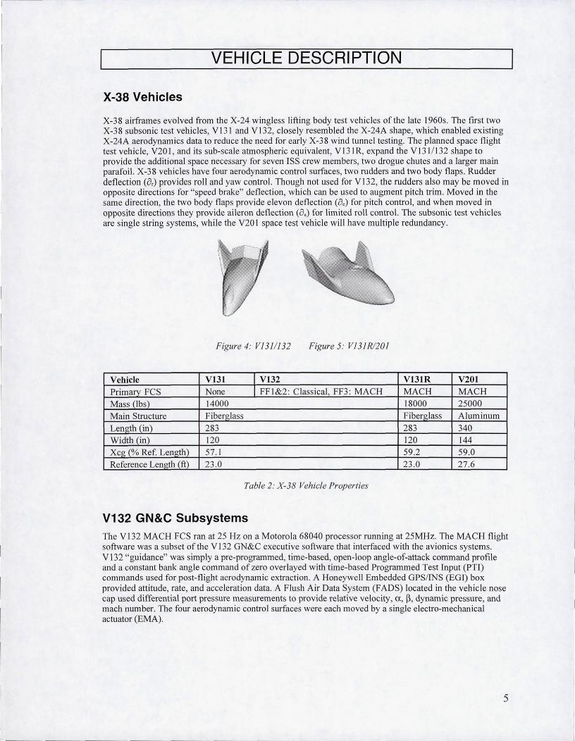
X-38 airframes evolved from the X-24 wingless lifting body test vehicles of the late 1960s. The fIrst two X-38 subsonic test vehicles, Vl31 and Vl32, closely resembled the X-24A shape, which enabled existing X-24A aerodynamics data to reduce the need for early X-38 wind tunnel testing. The planned space flight test vehicle, V201 , and its sub-scale atmospheric equivalent, V131R, expand the V1311132 shape to provide the additional space necessary for seven ISS crew members, two drogue chutes and a larger main parafoil. X-38 veillcles have four aerodynamic control surfaces, two rudders and two body flaps . Rudder deflection (a,) provides roll and yaw control. Though not used for V l32, the rudders also may be moved in opposite directions for "speed brake" deflection, which can be used to augment pitch trim. Moved in the same direction, the two body flaps provide elevon deflection (8e) for pitch control, and when moved in opposite directions they provide aileron deflection (aa) for limited roll control. The subsonic test vehicles are single string systems, while the V201 space test vehicle will have multiple redundancy.
Figure 4: V1311132 Figure 5: VJ31R1201
Vehicle VI31 I VI32 V13IR V20I Primary FCS None · I FF1&2 : Classical, FF3 : MACH MACH MACH Mass (lbs) 14000 18000 25000 Main Structure Fiberxlass Fibero-Iass Aluminum Length (in) 283 283 340 Width (in) 120 120 144 Xcg (% Ref. Length) 57.1 59 .2 59.0 Reference Len!rth (ft) 23 .0 23.0 27 .6
Table 2: X-38 Vehicle Prop erties
V132 GN&C Subsystems The V132 MACH FCS ran at 25 Hz on a Motorola 68040 processor running at 25MHz. The MACH flight software was a subset of the V132 GN&C executive software that interfaced with the avionics systems. V132 "guidance" was simply a pre-programmed, time-based, open-loop angle-of-attack command profile and a constant bank angle command of zero overlayed with time-based Programmed Test Input (PTI) commands used for post-flight aerodynamic extraction . A Honeywell Embedded GPS/INS (EGI) box provided attitude, rate, and acceleration data. A Flush Air Data System (FADS) located in the vehicle nose cap used differential port pressure measurements to provide relative velocity, a , ~ , dynamic pressure, and mach number. The four aerodynamic control surfaces were each moved by a single electro-mechanical actuator (EMA).
5

V132 Vehicle Safety Although V132 systems were "si.ngle string," i.e., no redundancy, many GN&C systems could "safe" the vehicle if a problem developed. V 132 software could initiate early flight termination and drogue deployment if attitude rates or dynamic pressure exceeded predeterm ined I imits. A FADS failure was handled by switching to a backup Navigation Air Data (NA VDAD) algorithm to provide EGI-derived estimates of vehicle relative velocity, ex, ~, dynamic pressure, and mach number. Communication faults and computational errors were monitored and, if persistent, could result in early flight termination . In the event of a total failure of the flight computer, drogue chute or parafoil, a backup chute could be deployed from the ground. Finally, the vehicle had a completely independent flight termination system triggered by a range safety officer if the vehicle strayed outside of its range boundary.
V132 Subsonic Aerodynamics and Uncertainties Lifting bodies provide significant challenges to FCS design. Short moment arms result in limited control authority and sluggish vehicle response, especially in roll. In fact, V 132 rudders were three times more effective in roll than the ailerons, which exemplifies the coupled nature of V 132 control. The blunt aft end induces asymmetric base flow which imparts yaw and roll moments upon the vehic le, as observed during V132 flight tests. Fortu.nately, these asymmetries were within the uncertainties of the Vl32 aerodynamic database used for FCS design. Base flow effects also degraded ai leron effectiveness.
Vector diagrams showing the contributions of effectors and attitude angles upon moment coefficients were used to assess stabi lity and controllability. Figure 6 contains rudder (left), aileron and ~ (right) vectors plotted on C1 vs. Cn axes . Uncertainty boxes drawn around each vector were used to determine worst case uncertainty combinations for FCS testing. Wide separation of vectors is desirable for controllability. An ideal ai.rcraft might have a nearly horizontal rudder vector and a longer, nearly vertical aileron vector, i.e. , pure roll and yaw axis controllers. Uncertainties or flight conditions which align the effector vectors resu lt in loss of effector independence- redundant effectors- and degraded controllability. Directional stability is reduced as the ~ vector moves left. ~ vector separation is required for bank angle controllability.
02
0.1
-0.1
-0.5
-0.6
-0.7
-0.8 -0.3
Beta, Aileron, and Rudder Vectors at Mach 0.5. Alpha:: 12. Vehicle 132 Nominal Aero with Uncertainty Boxes.
of< ~ ~ --. ~
it- ---"" " "' '" "' .....
-025 -0.2 ~. 15 -0.1 -0.05 0.05 " 0.15 02
V'a'NIng Moment coemclent
0.3
Figure 6: VJ32 Lateral-Directional Vector Diagram, M = 0.5, ex = 12°
Figure 6 shows the V132 vector diagram at M = 0.5 and ex = 12°. The relatively small aileron vector indicates the low effectiveness of the aileron compared to the rudder. The nominal aileron and rudder vectors are reasonably separated, but there are clearly points on the uncertainty boxes which align the two vectors, so the FCS had to be robust to this alignment case. The aileron and rudder vectors became more closely aligned near M = 1. However, the highest, fastest VI32 drop test, FF3, began at M = 0.6.
6

Lateral control departure parameters (LCDP) [1] for each effector are measures of bank control and numeric indicators of effector/~ vector alignment. The following equations define aileron and rudder LCDP in terms of stability derivatives, and provide inequality criteria for proverse bank angle control.
Aileron : LCDP< = C C1 - Cl C > 0 <Xl li p &, p 11&,
Rudder: LCDPor = ClIp Cllir - Clp C"1ir < 0 LCDP = 0 indicates effector/~ vector alignment and neutral bank control, i.e., any control deflection is offset by~, resulting in zero roll. An adverse LCDP, i.e. , reversal of either of the above inequalities, indjcates reversal of the corresponding effector' s bank control authority. For example, while positive aileron deflection normally results in positive roll , a negative aileron LCDP means that positive aileron combines with ~ to create negative roll- this is called "aileron reversal."
7

V132 MACH DESIGN
This section describes the control system design modifications developed to address the un~que issues associated with the 132 vehicle and flight test. Within the structure of the existing MACH architecture, bandwidth and CV selections were made to satisfy mission, flying qualities and stability margin requirements as stated in the previous section of this paper. Generally, this involved an iterative approach of gain selections tested in linear and nonlinear simulation. In addition, new algorithm changes evolved to handle uncertain aerodynamics, the lack of a sideslip measurement and the large but short disturbance from B52 release. More in-depth discussion of these may be found in references 1-3.
CV Selection
With good separation in elevon, aileron and rudder effectiveness for the anticipated flight near ex. = 12°, three CVs- LCV, MCV, and NCV- were chosen to independently control the three rotational axes- roll, pitch and yaw, respectively. The CVs definitions evolved from previous experience with classical flight contro l systems and other MACH applications (Table 1), using EGI body attitude, inertial rates, translational accelerations, and FADS measurements of ex., velocity and dynamic pressure:
LCV= Ps
MCV = q +_1_( 2.5 )nz + g cosycosf.1 - Ps
tanf3 - 0.003'1 - (~+ ~)COSy 400 s+2.5 Vcosf3 400 V
NCV = r, - 2~8 f3equiv - ~ cos y sin f.1
These were chosen to stabilize zero dynamics, complement ex. and <j> command tracking, and maintain coordinated flight in a steady wind . In NCV, a complementary filter approach (Figure 7) blended lowfrequency lateral acceleration (ny) with high-frequency estimated P (P est) to form an equivalent P (P equi v)
which would maintain zero sideslip in steady-state fli ght. The filter had a bandwidth of 0.5 rad/sec, near the controller bandwidth, and was inverted as part of the OBAC.
Post
POqUiV
Figure 7: NCV Filtered Sideslip Angle
Loop Design
Inner loop P+I compensation bandwidths were set to 1.0 rad/sec for LCV and NCV and 1.7 rad/sec for MCV by setting the KB design parameter to 2 and 3.4, respectively (see Figure 3). Anti-windup logic was employed to prevent integrator build-up during periods of surface saturation.
The outer loops tum ex. and <j> commands into MCV and LCV commands, respectively (Figure 2) . Outer loop gains, b$ = 0.4 and ba = 1.0, were based upon performance requirements and inner loop bandwidths. Note that angle-of-attack rate is computed in the OBAC and not sensed.
8

Beta Estimation
In general, MACH requires full-state feedback, and therefore requires a sideslip angle sensor for OBAC computations. Because FADS-computed sideslip angle was not available for feedback use on Vl32, four ~ estimation options were investigated: (1) specia l cases of KaLman filters, (2) inertial sideslip, (3) sideslip derived from lateral acceleration, and (4) zero sideslip. Option 1 was eliminated early because it was oversimplified and never tuned properly. Option 2 was unacceptable in steady winds where it is destabilizing at low frequenc ies. Option 3 led to poor stabi]jty margins. Option 4 ultimately was chosen.
Further rationale for option 4 came from a stability margin analysis for a typical flight condition and dynamic pressure. The analysis considered a low-passed measurement of sideslip angle as the control law sensor. The low pass filter break frequency was varied between 0 and 100 rad/sec. The best phase and gain margins were achieved for low break frequencies (Figure 8). In fact, approximating sideslip as zero gave the best robust stability. Also, the minimum closed-loop damping ratio is only slightly degraded with this approximation. Thus, the simplest option was selected, and the estimate of sideslip was set to zero.
50 .......... -'" ".''''''
40
30 ~-----------------
20
10
100*zmin I
Phase margin (deg)/ gain margin (db) ~
. -- - - - ----_ . --"-- --.-- .-._ .. . . -- .. .
O L---~--~~~~~~----~--~~--~~~----~--~~~~~
10.1
Figure 8: Nominal and Robust Stability Analysis of Low-Pass Filtered Sideslip
8-52 Transient
When Vl31 and VI32 separated from the starboard wing of the B-52, they experienced a strong downward pitch and positive roll and yaw moments due to the sway brace flow interference and down-wash and outwash effects from the B-52 wing and fuse lage . These dissipated quickly as the distance from the B-52 increased; however, for V132, the resulting high angular rate transient had to be active ly controlled . Though V132 control effectors could not overcome these forces , they were used at saturation limits to mitigate the disturbance as much as possible.
Due to the higb Iy nonlinear nature of this B-52 transient problem, 6-DOF simulation was used heavily to converge upon a viable solution. Nearly 80% of the control design effort was incurred solving this problem, primarily through trial and error. The solution that evolved consisted of two changes to the control algorithm and two associated with its initiation . These 4 changes are now presented.
9

Control Allocation The control allocation logic in MACH is based upon specified effector limits and preferences. Typically, when shared surfaces such as the body flaps are used for both elevon and aileron deflections, preference would be given to the elevon to satisfy the MCV (or angle-of-attack) command. Any remaining authority would then be availab le to the aileron to help satisfy the LCV (or bank angle) command. This scheme proved to be problematic when controlling the B-S2 disturbance: All available flap motion was allocated to the elevon, preventing adequate roll authority. As a solution for V132, SO% of the flap rate and 4° of flap position was reserved for use by the aileron when necessary. When not required by aileron, the reserve was made avai lable back to the elevon.
Figure 9 illustrates this "aileron reserve." The diamond bounds achievable elevon (vertical) and aileron (horizontal) deflections given that elevon is lim ited by the flap range of 0 to 40° and ai leron, while physically able to reach 20° in magnitude, is limited to ISO in software due to avai lable aerodynamic data. Aileron and elevon commands inside these limits will be achieved. For commands outside these limits, the pitch axis has priority except at the top and bottom corners of the diamond. Pitch priority is indicated by horizontal lines mapping commanded points outside the diamond to achievable points on or within the diamond. The 4° of aileron reserve is indicated in the top and bottom corners by the vertical lines mapping points outside the diamond to achievable points on the diamond . Thus, Figure 9 shows how desired elevon and aileron commands lying outside position limits are mapped to achievable commands.
45
40
35
30
25
20
15
10
5
0
-5 -20 -10 0 10 20
Figure 9: Achievable Elevon-Aileron Diamond
When V132 control surfaces hit rate or position limits and desired LCV and NCV rates could not be satisfied , MACH DI and a control allocation algorithm known as SMN (ref 7) used priority weighting to emphasize NCV errors S times more than LCV errors in establishing surface commands that approximately satisfied CV commands, i.e., "zero sideslip" took priority over "wings level" during the B-S2 transient.
Delayed Integrator Activation The desired dynamics used classical P+I compensation for frequency shaping and bandwidth selection. The NCV integrator charged up during the B-S2 transient despite the anti-windup logic and in some instances caused an undesirable negative ro ll overshoot, i.e., an "over-reaction" to the initia l positive roll transient. This was remedied by removing integral action in the NCV channel for the fLrst 3 seconds of flight. When the NCV integrator was activated at 3 seconds, the transition was smooth with no transient.
Control Law Activation Time The time at which the FCS was activated after release was a design parameter used to manage the B-S2 transient. Though the vehicle airframe was stable, it was determined that early activation of the control law was best. DFRC ana lysis confirmed there was no recontact issue, so MACH was activated at the earliest possible time of 0.32 seconds after release.
10
Initial Elevon Position The transient negative pitch rate caused the e1evon to initially move upward, pulling the nose back up. The downward pitching moment quickly disappeared, and the elevon, riding the rate limit, could react quickly enough to avoid an overshoot in angle-of-attack, often above the 20° "comfort zone" limit where rudder stall was feared. Setting the initia l position at a lower (relative to previous drop tests) deflection of 25° reduced this ex overshoot. Moving the elevon near the middle of its range also increased availab le aileron deflection . Special MACH initia lization software was developed to load the MCV integral state and produce an equal elevon command, thus avoiding a startup command error transient.
Robustness to Aerodynamic Uncertainties
MACH architecture enables frequency loop-shaping in the desired dynamics block to provide robust stability in the presence of high-frequency plant uncertainties (ref. 4). However, bandwidth selection alone provided insufficient robustness, i.e. stability marg ins, over the large range ofV132 aerodynamic uncertainties . A new tack to improve robustness involved the selection of the aerodynamic model used in the OBAC. Instead of a nominal aerodynamic model, a particular aerodynamic uncertainty set was selected to describe the dynamics in the OBAC. The resu It was increased robust stability with a small expense to nominal performance. The selection procedure is described below for the linear multivariable case and demonstrated with a ftrst order, 8[80 example.
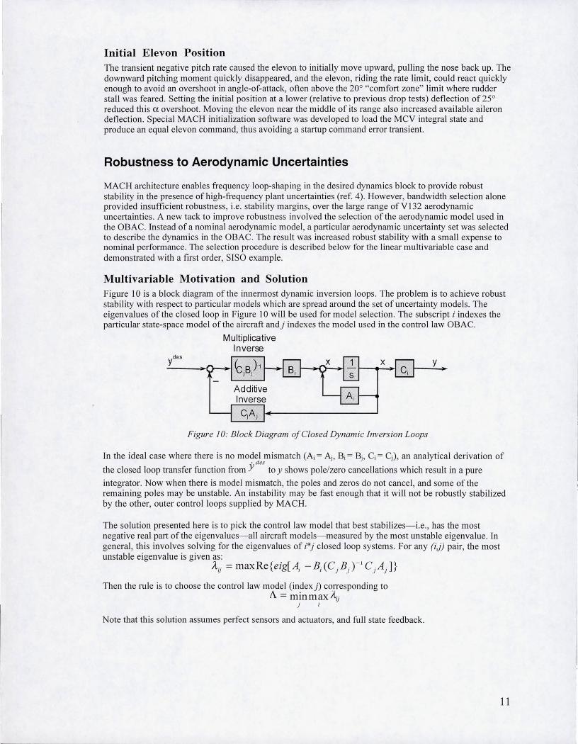
Multivariable Motivation and Solution Figure 10 is a block diagram of the innermost dynamic inversion loops. The problem is to achieve robust stability with respect to particular models which are spread around the set of uncertainty mode ls. The eigenvalues ofthe closed loop in Figure 10 will be used for model selection. The subscript i indexes the particular state-space model of the aircraft and) indexes the model used in the control law OBAC.
Mult ipl ica tive Inve rse
Ad di tive
Figure 10: Block Diagram of Closed Dynamic inversion Loops
y
In the ideal case where there is no model mismatch (Ai = Aj , Bi = Bj , C; = Cj ) , an analytical derivation of . des
the closed loop transfer function from Y to y shows pole/zero cancellations which resu lt in a pure
integrator. Now when there is model mismatch , the po les and zeros do not cancel, and some of the remaining poles may be unstable. An instability may be fast enough that it will not be robustly stabilized by the other, outer control loops supplied by MACH.
The solution presented here is to pick the control law mode l that best stabilizes-i .e. , has the most negative real part of the eigenvalues-all aircraft models- measured by the most unstable eigenvalue. In general, this involves solving for the eigenvalues of i*) closed loop systems. For any (i,)) pair, the most unstable eigenvalue is given as:
Aij = maxRe{eig[Aj -Bj(C j Bj f' CiAj ]}
Then the rule is to choose the control law model (index)) corresponding to A = minmaxAij
j
Note that this solution assumes perfect sensors and actuators, and full state feedback.
11
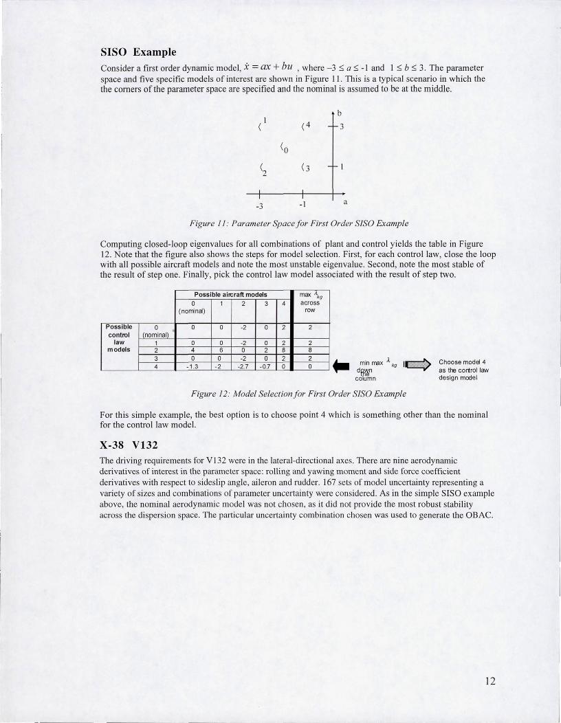
SISO Example Consider a first order dynamic model , x = ax + bu , where -3 :s; a :s; -I and I:S; b :s; 3. The parameter space and five specific models of interest are shown in Figure II . This is a typical scenario in which the the comers of the parameter space are specified and the nominal is assumed to be at the middle.
-3 -I
b
3
a
Figure J f: Parameter Space for First Order S1S0 Example
Computing closed-loop eigenvalues for all combinations of plant and contro l yields the table in Figure 12. Note that the figure also shows the steps for model selection. First, for each control law, close the loop with all possible aircraft models and note the most unstable eigenvalue. Second, note the most stable of the result of step one. Finally, pick the control law model associated with the result of step two.
Possible 0 control (nominal)
law 1 models 2
3 4
Possible airc raft models max '\g 0 1 2 3 4 across
(norrina) row
0 0 -2 0 2 2
0 0 -2 0 2 2 4 6 0 2 8 8 0 0 -2 0 2 2
-1 .3 -2 -2.7 -0 .7 0 0 .. d~~nmax A kg Ie::) column
Figure 12: Model Selectionfor First Order S1S0 Example
Choose model 4 as the control law design model
For this simple example, the best option is to choose point 4 which is something other than the nominal for the control law model.
X-38 V132 The driving requirements for V132 were in the lateral-directional axes . There are nine aerodynamic derivatives of interest in the parameter space: rolling and yawing moment and side force coefficient derivatives with respect to sideslip angle, aileron and rudder. 167 sets of model uncertainty representing a variety of sizes and combinations of parameter uncertainty were considered. As in the simple SISO example above, the nominal aerodynamic model was not chosen, as it did not provide the most robust stability across the dispersion space. The particular uncertainty combination chosen was used to generate the OBAC.
12

CERTIFICATION PROCESS
V 132 MACH FCS certification was the final pre-flight verification that the software met stability and performance requirements. Linear analysis verified gain and phase stabi lity margins, and nonlinear, 6-DOF simulation verified performance and stable oscillations.
Nonlinear Certification
A high-fidelity, 6-DOF simulation of X-38 veh icle dynamics with closed loop GN&C systems was used to look for V132 FCS instabilities and performance vio lations in a variety of dispersed stress cases. The X-38 simulation was derived from the Shuttle version of the Spacecraft Engineering Simu lator (SES), a mature engineering tool long used for system development and post flight trajectory reconstruction. The SES includes high-fidelity models of the environment (aerodynamics, gravity, winds, and atmosphere), flight hardware (actuators, sensors, control surfaces) and flight software (GN&C executive, FCS, etc.) . In addition to a ll-software simulations, the SES was hooked up to V 132 for rea l- time, closed- loop testing of hardware and software. For non linear certification, the SES ran in batch mode, varying deterministic "worst-case" combinations of aerodynamic, sensor, and initial condition parameters.
The V132 MACH non linear certification included a series of 18 test cases and 2000 simulated drops the SES. These SES runs verified that V132 would fly well in the given flight envelope, and examined system behavior beyond the expected flight envelope (Table 3).
Parameter Variation A lpha (ex) 8° 12° (nominal), 16°
Aerodynamics 34 worst case uncertainty sets B-52 interference effects 3-(J B-52 aerodynamic interference
Gusts, turbulence 20 fps gusts moderate turbu lence Mass properties Variations of Xc< Yeo Zeg. Ixx Ivv. Izz Winds 99% Edwards Port Tail Side, Shear System failures I surface failure, FADS failure. Initial drol> state Dispersions on initial position velocity, and heading. PTI 2 sets of aileron , rudder doublets .
Table 3: Parameter Variations/or Nonlinear Certification
For the planned fl ight trajectory at ex = 12°, the system met performance requirements and was robustly stable. However, for many lower ex = 8° trajectory cases, the system exhibited unstab le behavior, often losing ro ll control while maintaining pitch control. These "stability ro lls" were due largely to reversal in V132 aileron control authority at ex < 10°. Steps were taken to avoid such a low ex in the event ofa FADS failure, and software was added to start the drogue chute deployment sequence early if necessary.
Linear Certification
Though DI does not guarantee robust stability and performance, the MACH algorithm can be linearized to produce traditional stability margins and linear time responses at steady-state operating points [6]. These were relied upon heavily to evaluate des ign changes and measure closed-loop robustness. In fact, certification for fl ight mandated the closed- loop system meet SISO stabi lity margin requirements for selected "worst-case" aerodynamic uncertainty sets. In addition to stability margins, a more thorough multi-inputJmulti-output (MIMO) approach using structured singular va lue ()..L) techniques was utilized to determine stability and performance robustness over all possible combinations of aerodynamic perturbations. This section summarizes the results of these analyses .
13

Stability analyses were performed at dispersed flight conditions generated with 33 selected aerodynamic uncertainty sets [~Clb, ~Cldr, ~Clda, ~Cnb, ~Cndr, ~Cnda, ~CYb, ~CYdr, ~CYda, ~Cmo] representing 5-0" statistics along the nominal mission profile. Trajectory "snap shots" were taken at 10, 25 and 40 seconds after B-52 launch where steady-state conditions from the 6-DOF simulation were used to generate linear models. Controller models were built up from linearized OBAC models, created from actual flight code at the sensed flight conditions . Linear plant models included aerodynamic dispersions, sensor and actuator dynamics as well as avionics transport lags. Data characterizing the V 132 hardware was obtained through vendor specifications and vehicle end-to-end tests [ref Jay's web site, even though no one can see it?]. Table 4 summarizes the V132 linear model characteristics. Single loops were broken in 3 actuator (aileron, elevon, rudder) and 8 sensor (p, q, r, V, ex, <1> , e, ny) paths to compute open-loop gain and phase margins .
V132 Hardware Element Linear Model Definition
Accelerometer 1 st order: <Dn = 44 rad/sec Rate Gyro 1st order: <Dn = 66 rad/sec
Actuator Two 2nd -order: <Dn = 50 rad/sec, S = 0.7
<Dn = 26 rad/sec ( = 0.7
Transport Lag 40 ms
Table 4: V13 2 Hardware M odels
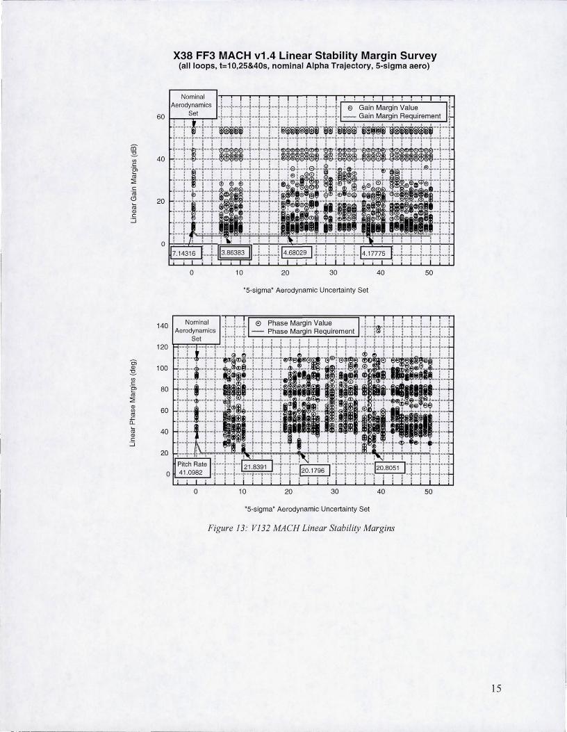
Results of the SISO linear analyses for the nominal 12 degree angle-of-attack profile are summarized in Figure 13 [ref Jay ' s presentation]. Even with 5-0" dispersions, the MACH controller was shown to meet 3-0" stability margin requirements except in one dispersed case in yaw-rate feedback.
A MlMO method for applying all 9 aerodynamic uncertainties simultaneously using J.l-analysis was developed to determine worst-case performance and gain and phase margins of the closed-loop system [9]. With this technique, fixed-size uncertainties were used to calculate the worst-case H x> gain of the performance transfer matrix. This same worst-case analysis method was used to calculate a conservative measure of the minimum combined gain and phase margins of each input/output. In doing this, the worstcase perturbation set for each channel was automatically determined. The results of these analyses using similar 5-0" dispersions are shown in Tables 5 and 6.
[Tables 5 & 6: show Balas results from AIAA paper, Tables 1 and 2]
14
X38 FF3 MACH v1.4 Linear Stability Margin Survey (all loops, t=10,25&40s, nominal Alpha Trajectory, 5-sigma aero)
140
o
Nominal Aerodynamics
Set
10 20 30
"5-sigma" Aerodynamic Uncertainty Set
120 R:::':F:r=R~·.··.-·-i-··.-·+--ii---i- ··.··i-·i·_·I---i··i-
Oi Q) 100 ~ (/) c
.~ 80 H-··+-"" -i·-i - 1II!ICI~lll ··t-· Cll ~
~ 60 t-:- .• +-.-~--~ Cll .r: 0...
~ 40 H-·+-··~··i···i·· c
::::;
o IL..--"';""'..J
o 10 20 30
"5-sigma" Aerodynamic Uncertainty Set
40
40
Figure J 3: V132 MACH Linear Stability Margins
50
50
15

FLIGHT TEST RESULTS
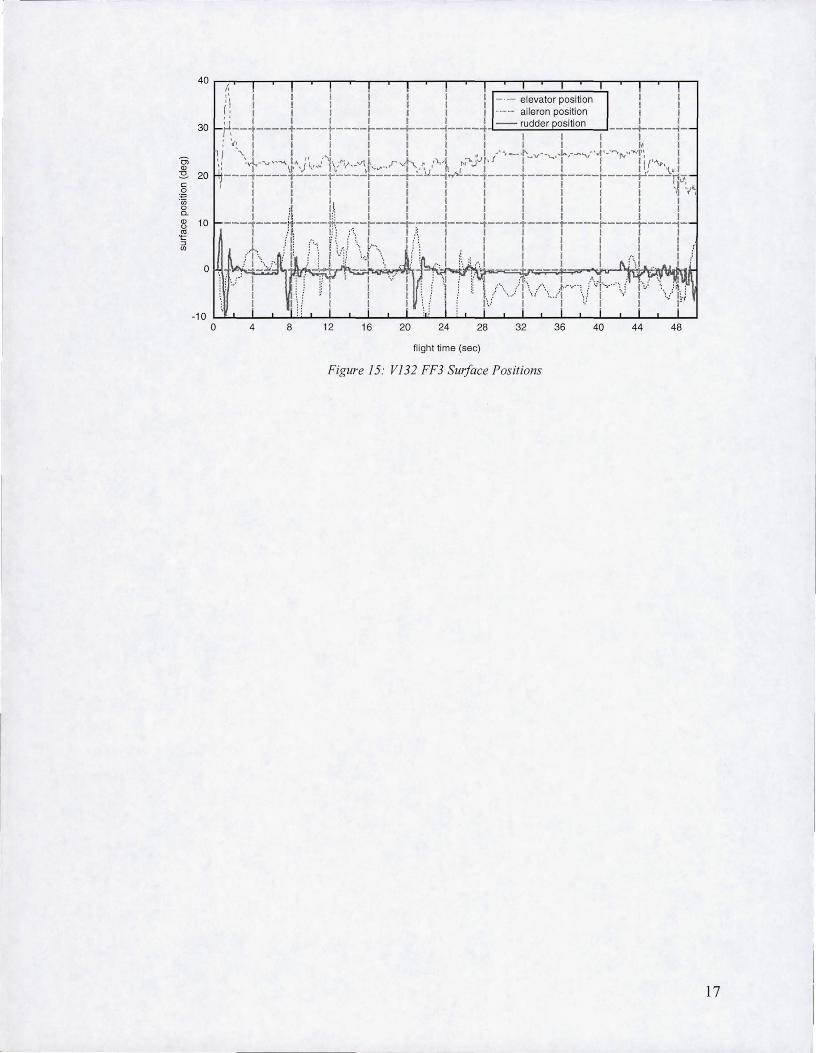
V132 FF3, the fLrst flight test of MACH, successfully occurred on March 30, 2000, at DFRC. V132 was dropped from the B-52 bomber at an altitude of 38,828 ft, a dynamic pressure of 125 psf and M = 0.6. The FCS was engaged at 0.32 seconds after B-52 release and terminated at drogue chute reposition approximately 50 seconds later. The 50 seconds of MACH controlled flight included 44 seconds of free flight and 6 seconds under the drogue chute. During the free flight, the pre-programmed, open-loop guidance commanded angle-of-attack through a profile of 12°, 15° and 11 ° while bank angle was commanded to zero. Three PTI test objectives were carried out, applying a double sweep of the rudders and ailerons at different angles-of-attack, then performing a bank PTI to study roll performance. The PTI data was used to better characterize the aerodynamics of the surfaces and vehicle. Atmospheric conditions were light-to-moderate turbulence with a 45 knot cross wind (starboard side) relative to the velocity at drop altitude. According to balloon data, the vehicle encountered a head/tail wind shear of about 40 knots midway through the flight during the ang le-of-attack maneuver. Flight reconstruction showed that the vehicle flew within its 3-0 dispersion envelope and MACH proved to be a Dr FCS capable of autonomously controlling an atmospheric lifting body.
20 ~,-~--~'-~~~~-r~--~~~--~~~--r-'-~--~'-~--~~~~
I I I I Third PT~Bank I .·· - t ~ I -- ', I 1 f
!=---:------.,....,...... f ' " , ,;" r, - ... '1 1 I 1 I I I ' , I I I I I
o
1 . .... "±_"_'~'~'" ' . _~--_~ .,J., I
~-- 1-~~-~! --- 11--~-!--:..r~·~·::1: ~' I I I I I
;J-+~Ar--.::r .. J '"=.r-Lr.t";;-I .... ~l ... I ",,' "l 1 • I I I I I I I I
I 1 1 I I 1 • 1 1 I I 1 1 . . I I
" I I. I 1 I - Roll (deg) I :: I I I I I I ... _. Alpha (deg) I I .10 ---~----~---- ____ L ___ ~ ___ ~ ____ ~_ __L ___ ~ ___ ~_
I I I I I I _ •. - Beta (deg) I I I I I I J I I ' I I I I 1 I First ~TI'DOUbI4 I Se'ond PTI .~oUblet I I
10
I I 1 1 I I I I I I J I I I I I
4 8 12 16 20 24 28 32 36 40 44 48
flight time (sec)
Figure 14: V132 FF3 Vehicle Attitude
16
40 f,
30
Ol CD
:E!. 20 c 0
+0 -in 0 0. CD 10 CJ ro t OJ U)
0
f:\ I I I I I I I -- elevator position I 'I 1 I 1 I I 1 -------- aileron position I
:' 1 I I I I I I I I r:--1----t----r----i----:----l----1 -- r,Udder P~sitio n ----:----1-:,~ 1 1 I I I , 1 1 1 I It I I '- 1 I 1 1 I 1 ,I .'''~-,,,, v--'-..-t..,-~"'-'vI'·~·rv,·-..1'~ 1
~, :J.--~"~, 1'1)"1 (1j'\-"if __ 'I'\~ rv.\ > ,'1.,,1 "' .... r-'t· f I" I I Ill''\,>. 1 , 1 II" ,'-' I" \I'''''~ I ," ,' fi ( • 1 I I I I. ,~, 1 ---~----T----r----r---~-~-4~~--~----T----r----r---~---n-
I 1 1 1 I I 1 1 I I 1 1 ,l""~,< 1 I 1 I I 1 I 1 1 I 1 " " 1 1 1 I I I 1 1 1 I 1 1 1 :1 1\ I I 1 1 I I 1 I 1 1 il Ii; I I 1 I I I 1 1 I
---~----tf'----'f!':.----r---;-:_--'1----~----T----r----r---~---"1-1 i ~ " ; :\ I I .:, 1 I 1 I 1 1 1
/f·,\-.r-/ it .r: i '<I \,l-\··,: _ I! ;.: '-', i !" '; t,! i ! i (\! 1.-
i \/' 1-- -:~ I -:1:1 t .:'-'. ,.'1'\ /\ J,.-.,--: {·';l--·-· -··,:, '1" '" I ~ 1 I ' i '-. .' 1 , 0' '. 0" 1 '.: I '" I 1 I I f:/ .. I" · .. ·1 1,:' 1 I
-10 o 4 8 12 16 20 24 28 32 36 40 44 48
flight time (sec)
Figure 15: V 132 FF3 Surface Positions
17

CONCLUSIONS
V132 presented many chalJenges for FCS design . Besides the inherently coupled dynamics and reduced controllability and stability of a subsonic lifting body, a primary design driver was tbe aerodynamic transient encountered when dropping away from the 8-52. Proper design oftbe MACH FCS helped make the maximum roll and sideslip angles due to B-52 interference in FF3 the lowest of all V132 free flights, despite FF3 being the fastest and highest ofthe three V132 flight tests . The MACH FeS design effort was able to meet robust stability requirements with a rapidly changing aerodynamic database- partly due to the "automatic gain scheduling" provided by the OBAC- that included relatively large uncertainties.
MACH successfully flew as an autonomous FCS in V 132 FF3 , the first flight test of thjs Honeywell imp lementation of the DI design technique. While MACH may have greater computational requirements than traditional , linear FCS design methods, the least-squares simplification of the aerodynamic database for the OBAC and the general streamlining of MACH source code enabled it to fit well within the computational budget of the V132 flight computer. Though DI is often considered primarily a highperformance control law design method, proper selection of outer loop gains and aerodynamic uncertainty set for the inner loop OBAC enabled MACH to meet all robust stability requirements . Despite being a nonlinear controller, MACH was linearized in order to take advantage of S1S0 and MIMO linear stability analyses . This MACH design was certified for V 132 FF3 with the same linear and nonlinear analyses previously used for the classical , Shuttle-derived FCS in FF 1 and FF2, i.e., the certification process was independent of the control law algorithm. The application of MACH to VI32 advanced DI FCS technology, thus helping to fulfill the "technology demonstration" goal of the X-38 Project.
18

ACKNOWLEDGEMENTS
Steven Labbe, Deputy Chief of Appl ied Aeroscience and CFD Branch, NASA-JSC Joe Gamble, JSC Jay Estes, NASA-JSC
NOTATION
0'. alpha or angle of attack
~ beta or angle of sides lip
Cn~ yawing moment coefficient due to beta
CI~ ro ll ing moment coefficient due to beta Cloa rolling moment coefficient due to aileron Clor ro lling moment coefficient due to rudder Cnoa yawing moment coefficient due to aileron CnOr ~winA moment coefficient due to rudder
REFERENCES
1. Moul, Martin T. and John W. Paulson. "Dynamic Lateral Behavior Of High-Performance Aircraft", NACA Report #RM L58E16. Unclassified.
2. Honeywell and Lockheed Martin, "Multivariable Control Design Guidelines", Fi nal Report, WLTR-96-3099, Wright Patterson AFB, OH, 1995.
3. Honeywell , "Application of MACH to X-38 Drop Test Vehicle 132", Phase I Final Report, NASA JSC Contract No. NAS9-19614, June 1997.
4. Enns, D., Bugajski D. , and Wacker, R.,"MACH Control Law Design and Analyses Review for X-38 Vl32, 30K B52 Drop Test", Presentation to NASA JSC Contract No. NAS9-19614, April 1999.
5. Enns, D. , Bugajski, D., Hendrick, R., and Stein, G. , "Dynamic Inversion: An Evolving Methodology for Flight Control Design", AGARD-CP-560, Turin, Italy, May 1994.
6. Honeywell , "Application of MACH to X-38 Drop Test Vehicle 132", Phase IT: Speed Enhancements, Linear Models & Linear Ana lysis, NASA JSC Contract No. NAS9-19614, May 1998 .
7. Bugajski, D. , and Enns, D. , "Nonlinear Control with Application to High Angle-of-Attack Flight", Journal of Guidance and Control, Vol. 15, No.3 June 1992.
8. Enns, D., "Control Allocation Approaches," AIAA Paper No. 98-4108, AIAA Guidance, Navigation, and Control Conference, Boston, MA 1998.
9. Shin, 1. Y., Balas, G., and Packard, A., "Worst Case Analysis of the Flight Control System X-38 Crew Return Vehicle", AIAA-99-4052, 1999
10. Ruppert, J. , "X-38 V-132 GN&C System Design Workbook", GN&C Requirements Document, November 1998
11. Ess, R., "Flight Test Objectives for VI32", X-38 FDT NO! #257, June 1999
19