ab&i foundry about us...cast iron effectively suppresses annoying “swooshing” sounds that...
TRANSCRIPT

AB&I Foundry • 7825 San Leandro Street • Oakland, CA 94621 • 800/GOT–IRON AB&I Foundry • 7825 San Leandro Street • Oakland, CA 94621 • 800/GOT–IRON 21
The Full-Line of Cast Iron Pipe and Fittings America Can TrustAB&I has been a leading West Coast producer of cast iron drain, waste and vent systems for decades. Now the high quality pipe and fittings that have distinguished AB&I as an industry leader are available nationwide.• Cast Iron No-Hub Pipe and Fittings • SV Gaskets• Cast Iron SV Pipe and Fittings • Accessories
All AB&I products are 100% made in America. All of our products have been carefully engineered to meet the most demanding industry standards, and are accepted for use by all plumbing codes in every jurisdiction in the United States. AB&I products are represented nationwide by an extensive network of Customer Service professionals, Regional Sales Managers, and Manufacturer’s Representatives, thoroughly dedicated to providing the highest level of customer service.
NSF-Certified to Ensure Full Standards ComplianceAll AB&I cast iron pipe and fittings have been certified by NSF International to meet applicable CISPI and ASTM standards. As more and more products with questionable compliance records enter the domestic market, it is critical that engineers, contractors, and inspectors have the ability to distinguish between products that meet the standards and those that may not. NSF Certification provides this assurance, giving all parties the peace of mind that comes from knowing they are installing unquestionably-compliant cast iron.
A Founding Member of the Cast Iron Soil Pipe Institute (CISPI)
AB&I has been a member of CISPI since its inception, and takes a great pride in helping sponsor this outstanding industry organization. CISPI has been instrumental in the promulgation of strong industry standards that have protected public health. CISPI conducts three unannounced, rigorous inspections of AB&I’s products and operations annually. By having both CISPI and NSF Marks, AB&I’s products pedigree is second to none.
About UsAB&I Foundry has been manufacturing cast iron soil pipe and fittings in America since 1906. We produce a full–line of standard and specialty cast iron soil pipe and fittings for drain, waste, and vent (DWV) plumbing systems. AB&I also provides custom gray iron foundry services for OEM manufacturers. All of our quality products are proudly made in the USA and meet all applicable ASTM and CISPI standards. Our basic principles embracing integrity and professionalism are what set us apart.
Our ValuesAt AB&I, we believe in...• Giving Team Members the chance to make decisions and learn from them• Open communications and honest Team Member evaluations• Sharing financial and business information with all Team Members• Promoting a safe and enjoyable workplace• The ability of every Team Member to make a positive contribution
AB&I FOUNDRY
ABOUT US
Sections of the 2,026 ft.² mural that surround AB&I Foundry

AB&I Foundry • 7825 San Leandro Street • Oakland, CA 94621 • 800/GOT–IRON AB&I Foundry • 7825 San Leandro Street • Oakland, CA 94621 • 800/GOT–IRON 43
CAST IRON ADVANTAGES
Cast Iron: The preferred choice for every application, above or below ground.
NON-COMBUSTIBLE, FIRE–RESISTANT
Cast iron is non-combustible and fire–resistant making it the safe choice for DWV systems. Cast iron is easy to install, and has superior durability often out lasting the life of a building. Its resistance to burning has the added benefit of requiring simple, low–cost fire stopping between the annular space between the pipe and wall penetration.
QUIETER OPERATIONS
Cast iron is often referred to as the “quiet pipe” because of its inherent density it provides superior noise suppression. Cast iron effectively suppresses annoying “swooshing” sounds that result from effluents cascading down from upper floors, resulting in a higher quality installation and a more satisfied customer. This sound attenuation feature can be a major benefit in quality residential and commercial construction, where building owners and tenants understand the advantage of iron by the very first flush.
STRONGER THAN OTHER MATERIALS
Cast iron is stronger, crush resistant, and longer–lasting than any other DWV piping material. Cast iron pipe installed over 300 years ago in many of Europe’s landmark buildings is still serviceable today, attesting to iron’s toughness and longevity.
RESISTANT TO CORROSION
Cast iron has been proven to be resistant to corrosion, even in the harshest soil environments with the most challenging effluents.
LOW THERMAL EXPANSION RATES
Cast iron expands and contracts in response to changing temperatures at a very low rate, reducing or eliminating the need for costly and time–consuming expansion joints.
SUGGESTED SPECIFICATION
BELOW GRADEAll drain, waste, vent, sewer and storm lines shall conform to the requirements of CISPI Standard 301*, ASTM A 888* or ASTM A74*. Pipe and fittings shall be marked with the collective trademark of the Cast Iron Soil Pipe Institute or receive prior approval of the engineer.
Building or house sewers shall be of cast iron soil pipe and fittings from the building drain to the point of connecting with the city sewer or disposal plant. All pipe and fittings shall conform to the requirements of CISPI Standard 301*, ASTM A888* or ASTM A74*. Pipe and fittings shall be marked with the collective trademark of Cast Iron Soil Pipe Institute or receive prior approval of the engineer.
ABOVE GRADEAll drain, waste, vent, sewer and storm lines shall conform to the requirements of CISPI Standard 301*, ASTM A888* or ASTM A74*. Pipe and fittings shall be marked with the collective trademark of the Cast Iron Soil Pipe Institute or receive prior approval of the engineer.
JOINTS• No–Hub Couplings shall conform to the CISPI Standard 310* and ASTM A1277• Heavy–Duty Couplings shall conform to the requirements of ASTM C1540• Compression Gaskets for Hub & Spigot shall conform to the requirements of ASTM Standard 564*
and ASTM C1563*• Joints for pipe and fittings shall conform to the manufacturer’s installation instructions and local
code requirements
* most current edition

AB&I Foundry • 7825 San Leandro Street • Oakland, CA 94621 • 800/GOT–IRON AB&I Foundry • 7825 San Leandro Street • Oakland, CA 94621 • 800/GOT–IRON 65
NO-HUB SOIL PIPE AND FITTINGSADAPTERS Hub Adapter 11 Tapped Adapter 11 Extended Tapped Adapter 11BENDS ¼ Bend 7 ¼ Bend w/ low heel inlet 7 ¼ Bend Tapped 7 ¼ Bend Extended 7 ¼ Bend w/extended low heel inlet 7 Double ¼ Bend 7 ¼ Bend Short Sweep 7 Extended Short Sweep 7 ¼ Bend Long Sweep 8 1/5 Bend 8 1/6 Bend 8 ⅛ Bend 8 ⅛ Bend Extended 8 1/16 Bend 8CLEANOUTS IBCO or Ferrule 15 Iron Body Tapped Cleanout 15 Two–Way Cleanout (Kelly) 15 Twin Cleanout (E. Bay Code) 15 Texas Twin Cleanout 15CLOSET BENDS Closet Bends 18 Closet Bends Reducing 18CLOSET FITTINGS Vented Closet Tee 17 Vented Closet Cross 17CLOSET FLANGES 2–252 Closet Flange 19CLOSET RINGS No–Hub Closet Rings 19 Best Set™ Closet Rings 19CROSSES Sanitary Cross 10 Sanitary Tap Cross 12FIGURE FITTINGS Figure 1 16 Figure 5 16 Figure 6 16 Figure 6 Double 16 Figure 8 16 Figure 8 Double 16 Figure 8 Double Extended 16PIPE Silverspun™ No–Hub Pipe 6FITTINGS Blind Plug Cleanout Fitting 15 Prison Fitting 13INCREASERS/REDUCERS Increasers–Reducers 11 Reducer (Short) 11
SPECIAL FITTINGS Rufwall 20STARTER FITTINGS 21–22 Trim Packages 23–24TEES Sanitary Tee 9 Sanitary Tap Tee 9 Test Tee 11 Double Verticle Tapped Tee 18 Horizontal Twin San Tapped Tee 18TRAPS “P” Traps 14 Side Inlet “P” Trap 14 Running Trap w/ single vent 14 “P” Trap w/ double vent 14 Deep Seal “P” Trap 14 “P” Trap Reducing 14VENT BYPASS 2” Bypass Vent Fitting 13WYE Wye 12 Comb Wye & ⅛ Bend 12 Dbl Comb Wye & ⅛ Bend 12 Double Wye 12 Upright Wye 12 Vented Tub Wye NH 13 Tapped Wye 18
HUB & SPIGOT PIPE & FITTINGSADAPTERS Double Hub Fitting 35BAR GRATE WITH LEGS 37BENDS ¼ Bend 29 ¼ Bend w/ low heel inlet 29 ¼ Bend Reducing 29 Double ¼ Bend 29 1/6 Bend 30 ⅛ Bend 30 1/16 Bend 30 Long ¼ Bend 29 Long ⅛ Bend 30 Long Sweep ¼ Bend 30 Single Hub Return Bend 30 Short Sweep ¼ Bend 29CLEANOUTS Twin Cleanout (Memphis) 35 Two–Way Double Cleanout 35CLOSET BENDS Closet Bends 37 Closet Bends Reducing 37 Closet Bends Regular Hub 37 Closet Bend Tapped 37CLOSET FLANGES 2–252 Closet Flange 37CLOSET FITTINGS Vented Closet Tee 39 Vented Closet Cross 39
CROSSES Sanitary Cross 32 Tapped Sanitary Cross 32 Straight Tapped Cross 32FERRULES 2–11 Standard Ferrule 37GASKETS EZ–TITE SV 44 Lubri/Fast® Lubricant 44 TY–SEAL 44 TY–SEAL Lubricant 44 TY–Tools 44INCREASERS/REDUCERS Reducer 35 Increaser 35 Long Plain Increaser 35 Long Tapped Increaser 35PIPE Hub & Spigot Pipe 28PLUGS Pipe Plug 35SISSION INSERTABLE JOINT 38STARTER FITTINGS 40–41 Trim Packages 42–43TAPPED SPIGOT 38TEES Sanitary Tee 31, 38 Tapped Sanitary Tee 31 Straight Tapped Tee 31 2–70 Test Tee (Type “A” less plug) 36 2–70 Test Tee (Type “A” with plug) 36 Long San Tapped Tee 38 Tapped Long Sweep Tee 38TRAPS “P” Trap 36, 39 Running Trap 36 Running Trap w/ Single Vent 36 Running Trap w/ 2 Hub Vents 36 “P” Trap w/ ½” Heel Tap 36 Deep Seal “P” Trap 36 VENT CAP WITH SCREW 38WYE Wye 33 Combination & ⅛ Bend 34 Double Comb & ⅛ Bend Wye 34 Double Wye 33 Wye with Side Inlet 34 Tapped Wye 38 Tapped Double Wye 38 Tapped Bath Vent Wye 38WARRANTY INFORMATION 48
TABLE OF CONTENTS
SILVERSPUN™ 10’ NO–HUB PIPEThe Finest No–Hub Pipe Available!
Part No. Size Unit Wt. Pcs/Pkg Total Ft. Pkg. Wt.
00156 1½” x 10’ 30 54 540 162000158 2 x 10’ 36 64 640 230400160 3 x 10’ 54 48 480 259200162 4 x 10’ 74 30 300 222000164 5 x 10’ 90 24 240 216000168 6 x 10’ 115 21 210 241500170 8 x 10’ 165 15 100 247500172 10 x 10’ 265 8 80 212000182 12 x 10’ 325 6 60 195000185 15 x 10’ 435 3 30 1305
DIMENSIONS AND TOLERANCESNO–HUB PIPE BARRELS
B Inside J Outside — T Thickness — Size Diameter Diameter Norm. Min. 1½” 1.50±.09 1.90±.06 .16 .13 2” 1.96±.09 2.35±.09 .16 .13 3” 2.96±.09 3.35±.09 .16 .13 4” 3.94±.09 4.38+.09–.05 .19 .15 5” 4.94±.09 5.30+.09–.05 .19 .15 6” 5.94±.09 6.30+.09–.05 .19 .15 8” 7.94±.13 8.38+13–.09 .23 .17 10” 10.00±.13 10.56±.09 .28 .22 12” 11.94±.13 12.50±.13 .28 .22 15” 15.11±.13 15.83±.13 .36 .30
QUALITY SILVERSPUN™
NO-HUB PIPE
AB&I Foundry • 7825 San Leandro Street • Oakland, CA 94621 • 800/GOT–IRON AB&I Foundry • 7825 San Leandro Street • Oakland, CA 94621 • 800/GOT–IRON 87
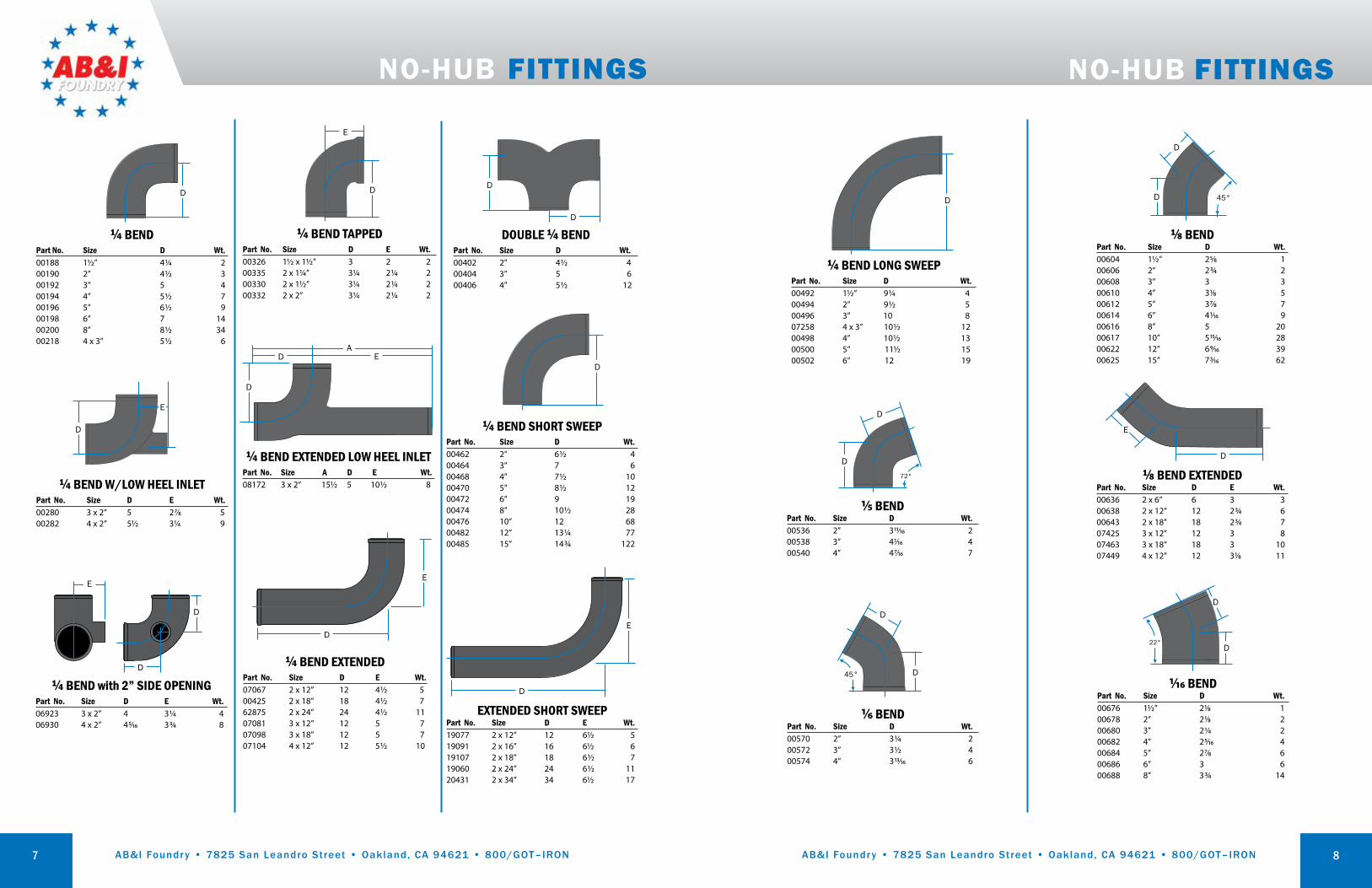
NO-HUB FITTINGS
¼ BEND TAPPED Part No. Size D E Wt.00326 1½ x 1½” 3 2 200335 2 x 1¼” 3¼ 2¼ 200330 2 x 1½” 3¼ 2¼ 200332 2 x 2” 3¼ 2¼ 2
D
E
¼ BEND with 2” SIDE OPENING Part No. Size D E Wt.06923 3 x 2” 4 3¼ 406930 4 x 2” 45/16 3¾ 8
E
D
D ¼ BEND EXTENDED Part No. Size D E Wt.07067 2 x 12” 12 4½ 500425 2 x 18” 18 4½ 762875 2 x 24” 24 4½ 1107081 3 x 12” 12 5 707098 3 x 18” 12 5 707104 4 x 12” 12 5½ 10
D
E
¼ BEND Part No. Size D Wt.00188 1½” 4¼ 200190 2” 4½ 300192 3” 5 400194 4” 5½ 700196 5” 6½ 900198 6” 7 1400200 8” 8½ 3400218 4 x 3” 5½ 6
D
¼ BEND W/LOW HEEL INLET Part No. Size D E Wt.00280 3 x 2” 5 27/8 500282 4 x 2” 5½ 3¼ 9
D
E
¼ BEND SHORT SWEEP Part No. Size D Wt.00462 2” 6½ 400464 3” 7 600468 4” 7½ 1000470 5” 8½ 1200472 6” 9 1900474 8” 10½ 2800476 10” 12 6800482 12” 13¼ 7700485 15” 14¾ 122
D
¼ BEND LONG SWEEP Part No. Size D Wt.00492 1½” 9¼ 400494 2” 9½ 500496 3” 10 807258 4 x 3” 10½ 1200498 4” 10½ 1300500 5” 11½ 1500502 6” 12 19
D
DOUBLE ¼ BEND Part No. Size D Wt.00402 2” 4½ 400404 3” 5 600406 4” 5½ 12
D
D
D
E
⅛ BEND EXTENDEDPart No. Size D E Wt.00636 2 x 6” 6 3 300638 2 x 12” 12 2¾ 600643 2 x 18” 18 2¾ 707425 3 x 12” 12 3 8 07463 3 x 18” 18 3 1007449 4 x 12” 12 31/8 11
EXTENDED SHORT SWEEPPart No. Size D E Wt.19077 2 x 12” 12 6½ 519091 2 x 16” 16 6½ 619107 2 x 18” 18 6½ 719060 2 x 24” 24 6½ 11 20431 2 x 34” 34 6½ 17
D
E
1/16 BENDPart No. Size D Wt.00676 1½” 21/8 100678 2” 21/8 200680 3” 2¼ 200682 4” 25/16 400684 5” 27/8 600686 6” 3 600688 8” 3¾ 14
D
D
22°
D
⅛ BENDPart No. Size D Wt.00604 1½” 25/8 100606 2” 2¾ 200608 3” 3 300610 4” 31/8 500612 5” 37/8 700614 6” 41/16 900616 8” 5 2000617 10” 515/16 2800622 12” 69/16 3900625 15” 73/16 62
D 45°
1/6 BENDPart No. Size D Wt.00570 2” 3¼ 200572 3” 3½ 400574 4” 313/16 6
D
D
45°
1/5 BENDPart No. Size D Wt.00536 2” 311/16 200538 3” 41/16 400540 4” 47/16 7
D
D
72°
NO-HUB FITTINGS
¼ BEND EXTENDED LOW HEEL INLET Part No. Size A D E Wt.08172 3 x 2” 15½ 5 10½ 8
D
D EA

AB&I Foundry • 7825 San Leandro Street • Oakland, CA 94621 • 800/GOT–IRON AB&I Foundry • 7825 San Leandro Street • Oakland, CA 94621 • 800/GOT–IRON9
SANITARY TEE (with 2” 90° side opening above center)
(New Orleans code)
Part No. Size C D E F G Wt.07838 3” LH 4½ 6 5 8½ 5 607852 3” RH 4½ 6 5 8½ 5 607876 3” R&L 4½ 6 5 8½ 5 707845 4” LH 5 6½ 5½ 91/8 5½ 1007869 4” RH 5 6½ 5½ 91/8 5½ 1007883 4” R&L 5 6½ 5½ 91/8 5½ 10
F
F
G
C
E
D
Right Inlet
SANITARY TAP TEEPart No. Size D E F Wt.01210 1½ x 1½” 3¼ 29/16 511/16 201212 2 x 1¼” 3¼ 213/16 511/16 301214 2 x 1½” 3¼ 213/16 511/16 301216 2 x 2” 3¾ 31/6 63/8 301220 3 x 1½” 3¼ 35/16 511/16 401222 3 x 2” 3¾ 39/16 63/8 401223 3 x 3” 47/8 43/16 8 701226 4 x 1½” 3¼ 313/16 511/16 501228 4 x 2” 3¾ 41/16 63/8 583277 4 x 3” 4½ 43/8 8 701232 5 x 1½” 3¾ 45/16 611/16 6 01234 5 x 2” 4¼ 49/16 715/16 7 01238 6 x 1½” 3¾ 413/16 6¾ 9 01240 6 x 2” 4¼ 51/16 77/16 8
D
F
E
NO-HUB FITTINGS
F
E
SANITARY TEEPart No. Size D E F Wt.00806 1½” 4¼ 4¼ 6½ 300808 2 x 1½” 4¼ 4½ 65/8 400810 2” 4½ 4½ 67/8 400812 3 x 1½” 4¼ 5 6½ 500814 3 x 2” 4½ 5 67/8 400816 3” 5 5 8 500818 4 x 2” 4½ 5½ 67/8 700820 4 x 3” 5 5½ 8 700822 4” 5½ 5½ 91/8 1100824 5 x 2” 5 6 8½ 900826 5 x 3” 5½ 6 95/16 1000828 5 x 4” 6 6 1013/32 1200830 5” 6½ 6½ 117/16 1300832 6 x 2” 5 6½ 83/8 1000838 6 x 3” 5½ 6½ 93/16 1100834 6 x 4” 6 6½ 101/16 1200840 6 x 5” 6½ 7 11½ 1700836 6” 7 7 12½ 1900844 8 x 3” 6 7½ 103/8 2000843 8 x 4” 6½ 7½ 11½ 2100848 8 x 5” 7 8 12½ 2300842 8 x 6” 7½ 8 13½ 2500850 8” 8½ 8½ 15½ 32
D
SANITARY TEE (with 2” 45° side opening above center)
(New Orleans code)Part No. Size D E F G Wt.00975 3” LH 6 5 8½ 5 600985 3” RH 6 5 8½ 5 687831 3” RH & LH 6 5 8½ 5 807920 4” LH 6½ 5½ 91/8 5½ 907944 4” RH 6½ 5½ 91/8 5½ 9
F
G
E
D
Left Inlet
10
F
Front View
Side View
E
C
G
D
SANITARY CROSS (with one 2" 90° sanitary
openings above center)(New Orleans code)
Part No. Size C D E F G Wt.09238 4” 5 6½ 5½ 91/8 5½ 11
SANITARY CROSS (with two 2” 90° sanitary opening
right & left above center)(New Orleans code)
Part No. Size C D E F G Wt.09221 3” 4½ 6 5 8½ 5 9 09245 4” 5 6½ 5½ 91/8 5½ 12
F
Front View
Side View
E
C
G
D
SANITARY CROSSPart No. Size D E F Wt.01850 1½” 4¼ 4¼ 6½ 301852 2” 4½ 4½ 67/8 401854 3 x 2” 4½ 5 67/8 601856 3” 5 5 8 701858 4 x 2” 4½ 5½ 67/8 701860 4 x 3” 5 5½ 8 801862 4” 5½ 5½ 91/16 1001864 6 x 4” 6 6½ 101/16 1401866 6” 7 12½ 7 2109160 8 x 4” 6½ 7½ 11½ 2689866 8” 8½ 8½ 15½ 29
D F
E
SANITARY TAP CROSSPart No. Size D E F Wt.09283 1½ x 1½” 3¼ 29/16 511/16 302014 2 x 1¼” 3¼ 213/16 511/16 302016 2 x 1½” 3¼ 213/16 511/16 402018 2 x 2” 3¾ 31/16 63/8 409337 3 x 1½” 3¼ 35/16 511/16 502024 3 x 2” 3¾ 39/16 63/8 502028 4 x 1½” 3¼ 313/16 511/16 602030 4 x 2” 3¾ 41/16 63/8 8
DF
E
F
E
GD
SANITARY CROSS (with 2” 45° sanitary opening same side)
(New Orleans code)Part No. Size D E F G Wt.09252 3” 6 5 8½ 5 809269 4” 6 5½ 91/8 5½ 11
NO-HUB FITTINGS

AB&I Foundry • 7825 San Leandro Street • Oakland, CA 94621 • 800/GOT–IRON AB&I Foundry • 7825 San Leandro Street • Oakland, CA 94621 • 800/GOT–IRON11
WYEPart No. Size D F G Wt.01312 1½” 4 6 2 201314 2” 45/8 65/8 2 301316 3 x 2” 55/16 65/8 1½ 401318 3” 5¾ 8 2¼ 601320 4 x 2” 6 65/8 1 601322 4 x 3” 6½ 8 111/16 701324 4” 71/16 9½ 27/16 801326 5 x 2” 7½ 81/16 15/16 701328 5 x 3” 8 911/16 111/16 901330 5 x 4” 8½ 113/16 27/16 1201332 5” 9½ 125/8 31/8 1501334 6 x 2” 8¼ 85/16 ½ 1001336 6 x 3” 8¾ 9¾ 1¼ 1301338 6 x 4” 9¼ 113/16 115/16 1601340 6 x 5” 10¼ 12½ 29/16 1701342 6” 10¾ 141/16 35/16 2101344 8 x 2” 93/8 8½ 9/16 1601346 8 x 3” 913/16 95/16 1/8 1801348 8 x 4” 103/8 117/16 15/16 2301350 8 x 5” 113/8 1213/16 15/8 2301352 8 x 6” 1113/16 143/16 215/16 2701354 8” 133/8 171/8 3¾ 4001362 10 x 4” 1111/16 125/8 ¾ 3701364 10 x 6” 131/8 157/16 23/16 4801365 10 x 8” 1411/16 183/8 35/8 5001366 10” 16½ 21½ 51/16 7601372 12” 19¾ 25½ 5¾ 10701375 15” 23¼ 30 6¾ 204
D
F
G
DOUBLE WYEPart No. Size D F G Wt.01538 2” 45/8 65/8 2 401540 3 x 2” 51/16 65/8 1½ 401542 3” 5¾ 8 2¼ 601544 4 x 2” 6 65/8 1 701546 4 x 3” 6½ 8 111/16 701548 4” 71/16 9½ 27/16 1201550 5 x 4” 8½ 113/16 27/16 1501552 6 x 4” 9¼ 113/16 115/16 1801554 6” 10¾ 141/6 35/16 23a74445 8 x 4” 103/8 117/8 25/16 2301557 8 x 6” 1113/16 143/16 25/16 3201556 8” 133/8 171/8 3¾ 50
G
F
D
UPRIGHT WYEPart No. Size F H E Wt.01646 2” 5½ 8½ 2 501648 3 x 2” 5½ 8½ 1½ 601650 3” 5½ 97/8 23/16 701652 4 x 2” 5½ 8½ 1 701654 4 x 3” 5½ 97/8 111/16 1001656 4” 6 11¼ 27/16 1408729 5 x 2” 6¾ 9½ 2 808750 5” 71/8 143/16 2¾ 21
F
E
COMBINATION WYE & ⅛ BENDPart No. Size D E F G Wt.01694 1½” 4¾ 53/8 6 2 301696 2 x 1½” 5 57/8 6 2 301698 2” 53/8 65/8 65/8 2 483062 3 x 1½” 5½ 6¾ 65/8 1½ 401700 3 x 2” 5½ 6¾ 65/8 1½ 601702 3” 75/16 8 8 2¼ 701704 4 x 2” 5½ 7¼ 65/8 1 701706 4 x 3” 7¼ 8½ 8 111/16 1001708 4” 9¼ 10 9½ 27/16 1401710 5 x 2” 515/16 7¾ 81/16 15/16 901712 5 x 3” 7¾ 9 911/16 111/16 1201714 5 x 4” 9¾ 10½ 113/16 27/16 1701716 5” 11¾ 12½ 125/8 31/8 2301718 6 x 2” 6 8¼ 85/16 ½ 1101720 6 x 3” 73/16 9½ 9¾ 1¼ 1401722 6 x 4” 9¾ 11 113/16 115/16 1701724 6 x 5” 1111/16 13 12½ 29/16 2101726 6” 135/8 143/8 141/16 35/16 2801728 8 x 4” 97/16 115/16 113/16 7/8 2601732 8 x 6” 12 133/8 1315/16 2¼ 3101734 8” 14¾ 159/16 1615/16 3¾ 46.5
FD
E
G
DOUBLE COMBINATION WYE AND ⅛ BEND
Part No. Size D E F G Wt.01802 2” 53/8 61/8 65/8 2 601804 3 x 2” 5½ 6¾ 65/8 1½ 601806 3” 75/16 8 8 2¼ 1201808 4 x 2” 5½ 7¼ 65/8 1 901810 4 x 3” 7¼ 8½ 8 111/16 1201812 4” 9¼ 10 9½ 27/16 20
FD
E
G
NO-HUB FITTINGSNO-HUB FITTINGS
11 12
TEST TEE (LESS BRASS PLUG)
IPS Part No. Size E F D Tap Wt.02046 2” 2 63/8 33/16 2 302048 3” 211/16 7¾ 37/8 3 602050 4 “ 3 87/8 47/16 4 1102052 5 “ 4½ 11½ 5¾ 5 1602054 6” 5 12½ 6¼ 6 2302056 8“ 6 15¼ 75/8 8 3802058 10” 6½ 20 10 10 59
E
DF
TEST TEE WITH TYPE A BRASS PLUG INSTALLED
IPS Part No. Size Tap E F D Wt.11736 2” 2 2 63/8 33/16 311743 3” 3 211/16 7¾ 37/8 611750 4” 4 3 87/8 47/16 1011767 5” 5 4½ 11½ 5¾ 1611774 6” 6 5 12½ 6¼ 2111781 8” 8 6 15¼ 75/8 34
HUB ADAPTERPart No. Size F X Wt.02222 2” 2 4½ 302224 3” 2 4¾ 302226 4” 2¼ 5¼ 5
F
REDUCER (SHORT)Part No. Size F Wt.02138 2 x 1½” 35/8 102140 3 x 2” 35/8 102142 4 x 2” 35/8 202144 4 x 3” 35/8 283314 5 x 2” 4 302148 5 x 3” 4 402150 5 x 4” 4 402152 6 x 2” 4 402154 6 x 3” 4 502156 6 x 4” 4 402158 6 x 5” 4½ 502160 8 x 2” 4½ 802162 8 x 3” 4½ 802164 8 x 4” 4½ 702166 8 x 5” 5 902168 8 x 6” 5 802172 10 x 4” 5½ 1602174 10 x 6” 6 1502175 10 x 8” 6 1502184 12 x 4” 6½ 2002186 12 x 6” 6½ 2002188 12 x 8” 7 2102190 12 x 10” 7½ 2502204 15 x 4” 7 3202206 15 x 6” 7 3502208 15 x 8” 7 3402210 15 x 10” 7½ 3802212 15 x 12” 7¾ 36
X
TAPPED ADAPTERPart No. Size F IPS Wt.02238 1½ x 1½ ” 25/8 1½ 102242 2 x 1½” 23/16 1½ 102244 2 x 2” 25/8 2 209948 3 x 2” 23/16 2 1
F
EXTENDED TAPPED ADAPTERPart No. Size F Wt.02280 2 x 1½ x 18” 18 602282 2 x 1½ x 18” 18 6
½"
¼"
F
INCREASER - REDUCER Part No. Size F Wt.09658 3 x 4” 8 5
F
X
H

AB&I Foundry • 7825 San Leandro Street • Oakland, CA 94621 • 800/GOT–IRON AB&I Foundry • 7825 San Leandro Street • Oakland, CA 94621 • 800/GOT–IRON13
VENTED TUB WYE 9–494 RHPart No. Size G H F Wt.18148 2” 9½ 3¾ 16 8
F
GH
VENTED TUB WYE 9–494 LHPart No. Size G H F Wt.18131 2” 9½ 3¾ 16 8
F
G
H
F
G
H
VENTED TUB WYE 9–474Part No. Size G H F Wt.01412 2 x 15” 9½ 5¼ 15 9
NO-HUB FITTINGS
PRISON FITTING(with top vent and 2” opt. tap “A”)
Part No. Size Description09112 4” Standard starter for prisons and correctional construction. Double 90° with single 2” top vent (9-502-A). Fully baffled. With tap.09114 4” Standard starter for prisons and correctional construction. Double 90° with single 2” top vent (9-502). Fully baffled. No Tap.09116 4” Standard starter for prisons and correctional construction. Double 90° with three 2” top vent (9-505). Fully baffled. No Tap. Part No. C G F Wt.09112 5¼ 7¾ 11¾ 22With Tap09114 5¼ 7¾ 11¾ 22No Tap09116 5¼ 7¾ 11¾ 22Plain
G
C
F
2” VENT BYPASS(right or left hand inlet)
Part No. Description A Wt.09500 9-473 - PLAIN – 1009502 9-473-B - RH – 1109522 9-473-A - LH – 1109524 9-473-A/B - DBL – 11
5¼
183/86½
9½
Right Shown
14
"P" TRAP WITH 1½” TAPPED SIDE INLET
Part No. Size Wt.02602 2 x 1½” LH 602604 2 x 1½” RH 6
53/16
“P” TRAPPart No. Size D J Wt.02506 1½” 6¾ 3½ 302508 2” 7½ 4 402510 3” 9 5½ 902512 4” 10½ 6½ 1702514 6” 14 7½ 30
LONG “P” TRAPPart No. Size D J Wt.02527 2 x 12” 12 4 802530 2 x 18” 18 4 9
J
D
RUNNING TRAP(with 4” single vent)
Part No. Size D E F G Wt.02570 4 x 4” 6½ 4½ 15 10½ 20
D
FE G
NO-HUB FITTINGS
“P” TRAP (with tapped inlet)
Part No. Size D J Wt.02586 2 x 1½” 7½ 4 402588 2” 7½ 4 5
J
D
“P” TRAP (REDUCING)Part No. Size D J Wt.08548 3 x 2” 9 5½ 10
J
D
J
D
DEEP SEAL “P” TRAPPart No. Size D J Wt.02600 2” 7½ 7 602610 3” 9 7 1302567 4” 10½ 8 17
“P” TRAP (with 2” no-hub side inlet)
Part No. Size C D J Wt.
19268 2” LH 13/16 7½ 31/16 519275 2” RH 13/16 7½ 31/16 5
Right Hand Illustration
Side View
Top ViewJ
C
D
“P” TRAP (with ½” Tap Primer)
Part No. Size D J M Tap Wt.08530 2” 7½ 4 2 ½ 508532 3” 9 5½ 2 ½ 1008534 4” 10½ 6½ 2 ½ 18
D
J
M
RUNNING TRAP WITH DOUBLE VENTPart No. Size C D E F G Wt.02576 4” 6 6½ 4½ 15 10½ 21
CE EG
DD
F
VENTED TUB WYE 9–484 RHPart No. Size E F G Wt.
2” 12 5¼ 15¾01414 8
F
G
E

AB&I Foundry • 7825 San Leandro Street • Oakland, CA 94621 • 800/GOT–IRON AB&I Foundry • 7825 San Leandro Street • Oakland, CA 94621 • 800/GOT–IRON15
TWO-WAY CLEANOUT FITTING (Kelly)
Part No. Size E D F Wt.08442 3 x 3 x 4” 7½ 9 15 1508446 4 x 4 x 4” 93/16 9½ 183/8 26
D
E
F
TWIN CLEANOUT(East Bay code)
Part No. Size F E Wt.02990 4 x 4 x 4” 7½ 7½ 15
E
F F
TEXAS TWIN CLEANOUTPart No. Size D E F G Wt.03004 4 x 4 x 4” 8¼ 2¾ 12 6½ 19
G EE
D
F
NO-HUB FITTINGS
IRONBODY CLEANOUT (FERRULE)(tapped)
Part No. Size Tap A B C Wt.08562 2” 1½ 23/16 23/8 ¾ 108564 3” 2½ 23/16 33/8 ¾ 208566 4” 3½ 23/16 47/16 ¾ 208568 5” 4 4½ 55/16 1 708570 6” 5 4½ 65/16 1 808572 8” 6 45/8 83/8 1 11
A
C
B
IBCO (Ferrule)(with Type A brass plug installed)
Part No. Size A Tapping Wt.12108 2” 1¾ 1½ 112115 3” 1¾ 2½ 112122 4” 1¾ 3½ 212139 5” 1¾ 4 612146 6” 1¾ 5 712153 8” 2¼ 6 10
16
FIGURE 1 Part No. Size D E F Wt.08002 2 x 2 x 1½ x 1½” 47/8 33/16 7 5
DF
E
FIGURE 5Part No. Size D E F Wt.08052 2” 6½ 5 8 608054 3x2x3” 87/8 69/16 9¼ 1108056 3” 87/8 69/16 101/8 1108058 4x2x4” 10¼ 7¾ 11½ 1708062 4” 10¼ 7¾ 12 17
DF
E
FIGURE 8 RIGHT/LEFTPart No. Size D E F H Wt.08136 3 x 2” - right 79/16 51/16 11 37/16 1308138 3 x 2” - left 79/16 51/16 11 37/16 1308140 4 x 2” - right 9 6½ 13 4 2108142 4 x 2” - left 9 6½ 13 4 21
Left Shown
D
H
E
F
FIGURE 6 RIGHT/LEFT Part No. Size D E F Wt.08100 3 x 2” - right 79/16 51/16 11 1108102 3 x 2” - left 79/16 51/16 11 1108104 4 x 2” - left 9 6½ 13 1808106 4 x 2” - right 9 6½ 13 18
D
E
F
Left Shown
45°
FIGURE 6 DOUBLE W/ FULL BAFFLEPart No. Size D E F Wt.08127 3 x 2” 79/16 51/16 11 1308112 4 x 2” 9 6½ 13 23
D
E
45°F
NO-HUB FITTINGS
FIGURE 8 DOUBLE W/ FULL BAFFLEPart No. Size D E F C H Wt.08159 3x2” 79/16 51/16 11 41/8 37/16 13
H
E
D
F
C
BLIND PLUGPart No. Size F Wt.02480 1½” 1¾ 102482 2” 1¾ 102484 3” 1¾ 102486 4” 1¾ 202488 5” 1¾ 202490 6” 1¾ 302492 8” 2¼ 602494 10” 3 1302496 12” 3½ 1802498 15” 3½ 33
F
FIGURE 8 DOUBLE EXTENDED FULL BAFFLE
Part No. Size H D E F C Wt.08163 4 x 2” 8 9 6½ 13 4½ 23
F
E
H
D
AB&I Foundry • 7825 San Leandro Street • Oakland, CA 94621 • 800/GOT–IRON AB&I Foundry • 7825 San Leandro Street • Oakland, CA 94621 • 800/GOT–IRON
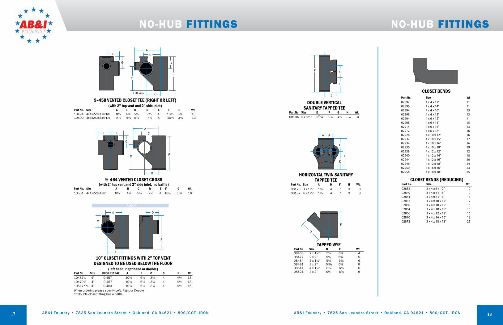
CLOSET BENDSPart No. Size Wt02892 4 x 4 x 12” 1102896 4 x 4 x 14” 1102894 4 x 4 x 16” 1502898 4 x 4 x 18” 1302904 4 x 6 x 12” 1102908 4 x 6 x 15” 1502914 4 x 6 x 16” 1302912 4 x 6 x 18” 1602924 4 x 10 x 12” 1602932 4 x 10 x 15” 1702934 4 x 10 x 16” 1602936 4 x 10 x 18” 1902938 4 x 12 x 12” 1202940 4 x 12 x 14” 1802944 4 x 12 x 16” 2002946 4 x 12 x 18” 2402950 4 x 16 x 16” 2302954 4 x 18 x 18” 25
CLOSET BENDS (REDUCING)Part No. Size Wt.02832 3 x 4 x 6 x 12” 1002840 3 x 4 x 6 x 15” 1002844 3 x 4 x 6 x 18” 1302852 3 x 4 x 10 x 12” 1202860 3 x 4 x 10 x 15” 1602864 3 x 4 x 10 x 18” 1602866 3 x 4 x 12 x 12” 1602870 3 x 4 x 16 x 16” 1802872 3 x 4 x 18 x 18” 25
17
NO-HUB FITTINGS
9–458 VENTED CLOSET TEE (RIGHT OR LEFT)(with 2” top vent and 2” side inlet)
Part No. Size A B C D E F G Wt.10494 4x4x2x2x4x4”RH 8⅛ 4¼ 5¼ 7½ 4 10½ 3¾ 1310500 4x4x2x2x4x4”LH 8⅛ 4¼ 5¼ 7½ 4 10½ 3¾ 13
CA
B
G G
D
E
F
Left View
9–464 VENTED CLOSET CROSS(with 2” top vent and 2” side inlet, no baffle)
Part No. Size A B C D E F G Wt.10531 4x4x2x2x4x4” 8⅛ 4¼ 5¼ 7½ 4 10½ 3¾ 16
CA
B
G
D
EE
F
10” CLOSET FITTINGS WITH 2” TOP VENT DESIGNED TO BE USED BELOW THE FLOOR
(left hand, right hand or double)Part No. Size UPC# 611942 A B C D F Wt.10487 L 4” 9-457 10¾ 6½ 3¾ 4 4½ 13 10470 R 4” 9-457 10¾ 6½ 3¾ 4 4½ 13 10517**D 4” 9-463 10¾ 6½ 3¾ 4 4½ 15When ordering please specify Left, Right or Double **Double closet fitting has a baffle.
C
B
F
A
D
18
NO-HUB FITTINGS
DOUBLE VERTICAL SANITARY TAPPED TEE
Part No. Size E F G H Wt.08194 2 x 1½” 213/16 9¾ 4½ 3¼ 4
F G
H
E
HORIZONTAL TWIN SANITARYTAPPED TEE
Part No. Size A D F H Wt.08170 3 x 1½” 1⅜ 4 7 3 8 08187 4 x 1½” 1⅜ 4 7 3 8
F
H
D
A A
TAPPED WYEPart No. Size D F Wt.08460 2 x 1½” 51/16 6⅝ 4 08477 2 x 2” 51/16 6⅝ 5 08484 3 x 1½” 5¾ 6⅝ 6 08491 3 x 2” 513/16 6⅝ 6 08514 4 x 1½” 67/16 6⅝ 6 08521 4 x 2” 6½ 6⅝ 8
F
D

AB&I Foundry • 7825 San Leandro Street • Oakland, CA 94621 • 800/GOT–IRON AB&I Foundry • 7825 San Leandro Street • Oakland, CA 94621 • 800/GOT–IRON19
CLOSET RING (No-hub)
Part No. Size A B F Wt.02966 4 x 3 x 3½” 4 3 3½ 402970 4 x 4” 4 4 4 5
*Used with no-hub coupling
7¼A Min.
F Min.
B
BEST SET™ CLOSET RINGPart No. Size Box Qty Wt.08020 4 x 2” (with test cap) 12 308021 4 x 2” 12 308022 4 x 4” 8 408023 4 x 4” (with test cap) 8 408024 4 x 3” (with test cap) 12 3
2–252 CLOSET FLANGE(caulk joint application)
Part No. Size x Height A B D Wt.022848 4x1” 6¼ 7¼ 1 2022855 4x1½” 6¼ 7¼ 1½ 28003 4x2” 6¼ 7¼ 2 28013* 4x2” 63/8 7¼ 2 2.8022879 4x2½” 6¼ 7¼ 2½ 3022886 4x3” 6¼ 7¼ 3 48005 4x4” 6¼ 7¼ 4 5022930* 4x4” 61/8 7¼ 4 5022909 4x5” 6¼ 7¼ 5 68017 4x6” 6¼ 7¼ 6 68015 4x2”, 1” Offset 6 7 2 2.58018 4x4”, 2” Offset 6¼ 7¼ 4 4.5022947 4x3”, 3” Reducing 6¼ 7¼ 3 38007 4x2” 6¼ 7¼ 2 38011 4x4 x 4” 6¼ 7¼ 4 48019 4x3 x 2½” 6¼ 7¼ 2½ 3
*Portland Code, two ¼” taps on top
B
D
A
B
D
A
B
D
A
B
A
D
NO-HUB FITTINGS
20
Long QuarterBend
Stack By-PassFitting
Long DoubleSweep San Tee
ExtendedSan Tap Tee
ExtendedShort Sweep
Right HandSingle Starter
Fitting
Tub VentWye
Side InletP-Trap
RUFWALLNO-HUB SPECIAL FITTINGS
RufWall Savings with Back Outlet Fixtures (Compared with Conventional Piping)• Fewer floor penetrations• Eliminates cost of dropped ceilings to conceal pipe• No scaffolding needed• One-man installation• Waist-high venting• Water closet easier to intall...faster
NOTE:Rufwall fittings are sold and shipped as normal cataloged soil products.
This publication contains the information needed to place orders with your customer service representative.
The by-pass fitting permits in-line piping to reduce width of the chase, and individual venting of the lavatories.Tub wye fittings accept waste from two tubs and provide a common vent. They save space, materials and the labor to install duplicate systems.
AB&I Foundry • 7825 San Leandro Street • Oakland, CA 94621 • 800/GOT–IRON AB&I Foundry • 7825 San Leandro Street • Oakland, CA 94621 • 800/GOT–IRON
NO-HUB FITTINGS
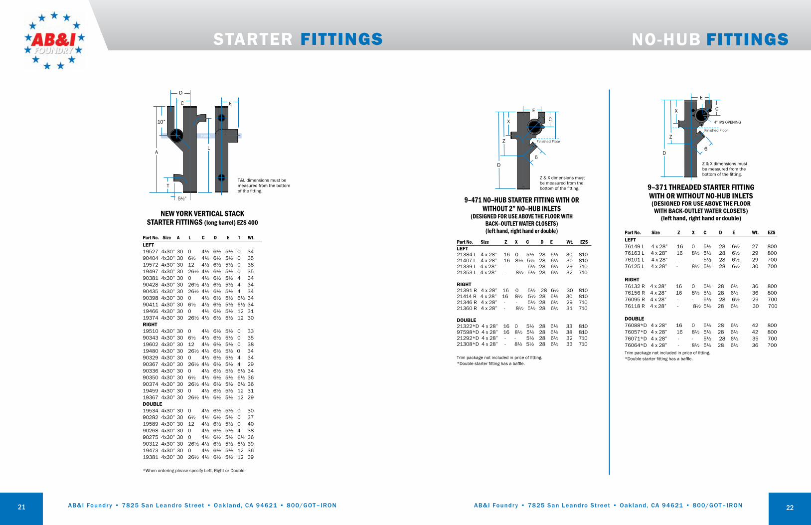
Part No. Size Z X C D E Wt. EZSLEFT21384 L 4 x 28” 16 0 5½ 28 6½ 30 81021407 L 4 x 28” 16 8½ 5½ 28 6½ 30 81021339 L 4 x 28” - - 5½ 28 6½ 29 71021353 L 4 x 28” - 8½ 5½ 28 6½ 32 710
RIGHT21391 R 4 x 28” 16 0 5½ 28 6½ 30 81021414 R 4 x 28” 16 8½ 5½ 28 6½ 30 81021346 R 4 x 28” - - 5½ 28 6½ 29 71021360 R 4 x 28” - 8½ 5½ 28 6½ 31 710
DOUBLE 21322*D 4 x 28” 16 0 5½ 28 6½ 33 81097598*D 4 x 28” 16 8½ 5½ 28 6½ 38 81021292*D 4 x 28” - - 5½ 28 6½ 32 71021308*D 4 x 28” - 8½ 5½ 28 6½ 33 710
Trim package not included in price of fitting. *Double starter fitting has a baffle.
X C
Z & X dimensions must be measured from the bottom of the fitting.
E
Z
D
Finished Floor
6
9–371 THREADED STARTER FITTING WITH OR WITHOUT NO-HUB INLETS (DESIGNED FOR USE ABOVE THE FLOOR
WITH BACK-OUTLET WATER CLOSETS)(left hand, right hand or double)
Part No. Size Z X C D E Wt. EZS LEFT76149 L 4 x 28” 16 0 5½ 28 6½ 27 800 76163 L 4 x 28” 16 8½ 5½ 28 6½ 29 80076101 L 4 x 28” - - 5½ 28 6½ 29 700 76125 L 4 x 28” - 8½ 5½ 28 6½ 30 700
RIGHT76132 R 4 x 28” 16 0 5½ 28 6½ 36 800 76156 R 4 x 28” 16 8½ 5½ 28 6½ 36 80076095 R 4 x 28” - - 5½ 28 6½ 29 700 76118 R 4 x 28” - 8½ 5½ 28 6½ 30 700
DOUBLE76088*D 4 x 28" 16 0 5½ 28 6½ 42 800 76057*D 4 x 28” 16 8½ 5½ 28 6½ 42 80076071*D 4 x 28” - - 5½ 28 6½ 35 700 76064*D 4 x 28” - 8½ 5½ 28 6½ 36 700Trim package not included in price of fitting. *Double starter fitting has a baffle.
X
Z
C
Z & X dimensions must be measured from the bottom of the fitting.
E
D
4” IPS OPENING
Finished Floor
6
9–471 NO–HUB STARTER FITTING WITH OR WITHOUT 2” NO–HUB INLETS
(DESIGNED FOR USE ABOVE THE FLOOR WITH BACK–OUTLET WATER CLOSETS)(left hand, right hand or double)
22
STARTER FITTINGS
NEW YORK VERTICAL STACKSTARTER FITTINGS (long barrel) EZS 400
Part No. Size A L C D E T Wt.LEFT19527 4x30” 30 0 4½ 6½ 5½ 0 3490404 4x30” 30 6½ 4½ 6½ 5½ 0 3519572 4x30” 30 12 4½ 6½ 5½ 0 3819497 4x30” 30 26½ 4½ 6½ 5½ 0 3590381 4x30” 30 0 4½ 6½ 5½ 4 3490428 4x30” 30 26½ 4½ 6½ 5½ 4 3490435 4x30” 30 26½ 4½ 6½ 5½ 4 3490398 4x30” 30 0 4½ 6½ 5½ 6½ 3490411 4x30” 30 6½ 4½ 6½ 5½ 6½ 3419466 4x30” 30 0 4½ 6½ 5½ 12 3119374 4x30” 30 26½ 4½ 6½ 5½ 12 30RIGHT19510 4x30” 30 0 4½ 6½ 5½ 0 3390343 4x30” 30 6½ 4½ 6½ 5½ 0 3519602 4x30” 30 12 4½ 6½ 5½ 0 38 19480 4x30” 30 26½ 4½ 6½ 5½ 0 3490329 4x30” 30 0 4½ 6½ 5½ 4 3490367 4x30” 30 26½ 4½ 6½ 5½ 4 2990336 4x30” 30 0 4½ 6½ 5½ 6½ 3490350 4x30” 30 6½ 4½ 6½ 5½ 6½ 36 90374 4x30” 30 26½ 4½ 6½ 5½ 6½ 3619459 4x30” 30 0 4½ 6½ 5½ 12 3119367 4x30” 30 26½ 4½ 6½ 5½ 12 29DOUBLE19534 4x30” 30 0 4½ 6½ 5½ 0 3090282 4x30” 30 6½ 4½ 6½ 5½ 0 3719589 4x30” 30 12 4½ 6½ 5½ 0 4090268 4x30” 30 0 4½ 6½ 5½ 4 3890275 4x30” 30 0 4½ 6½ 5½ 6½ 3690312 4x30” 30 26½ 4½ 6½ 5½ 6½ 3919473 4x30” 30 0 4½ 6½ 5½ 12 3619381 4x30” 30 26½ 4½ 6½ 5½ 12 39
*When ordering please specify Left, Right or Double.
D
C E
L
10”
5½”
A
TT&L dimensions must be measured from the bottom of the fitting.
21

AB&I Foundry • 7825 San Leandro Street • Oakland, CA 94621 • 800/GOT–IRON AB&I Foundry • 7825 San Leandro Street • Oakland, CA 94621 • 800/GOT–IRON
TRIM PACKAGE FOR
STARTER FITTINGS
support leg
DB
A
C
3”17”12
4½
7¼B.C.½ - 13 UNC - 2B(4) places
⅝ - 11 UNC - 2B(5) places
6¾B.C.4½
7½67/32
3⅜3¾
20
⅜
½⅜
3
⅝
1
⅞
⅜
⅜
¾
19⅞4¼
2⅛
30˚
30˚
4½
3⅛
⅝
⅝
⅝
1¼
9/16 ¾
2⅜
⅝⅞
1½
1
11/32
1¼
1 17/16
511/16
5/16
67/16
115/16
23/162⅛
5⅝
5⅝
17¾
15/32TYP
3° TYP
23/32
12⅜
3⅛
4½6
1115/16
45/16
R 213/16R 311/16
R ⅞
19/16
1
(6) p
lace
s
front viewside view
front view side view
EZS 22 EXTENDED LEG(left or right)
EZS 22 SUPPORT LEG
23
TRIM PACKAGE FOR
STARTER FITTINGS
1 — 4” PVC Sch. 80 NIPPLE with TEST CAP1 — BOWL GASKET4 — ⅝” X 12” RODS4 — ⅝” CHROME CAP NUTS8 — ⅝” JAM NUTS4 — ⅝” FLAT WASHERS4 — ⅝” FIBER WASHERS3 — ⅜” X 1½” BOLTS FOR FACEPLATE3 — ⅜” FLAT WASHERS4 — ⅝” STAR WASHERS
1 — 4” PVC Sch. 80 NIPPLE with TEST CAP1 — BOWL GASKET2 — 5/16” X 12” RODS2 — 5/16” HEX NUTS2 — 5/16” FLAT WASHERS2 — 5/16” CAP NUTS
1. IDENTIFY THE MAJOR COMPONENTS OF THE EZS 24 TRIM PACKAGE AND EZS 22 SUPPORT FRAME.
2. SECURE EZS 22 SUPPORT FRAME TO INSTALLED STARTER FITTING USING ⅜” X 1½” BOLTS AND ⅜” FLAT WASHERS.
3. SECURE RIGHT AND LEFT LEGS TO THE EZS 22 FACEPLATE USING ½” X 1¼” BOLTS AND ½” FLAT WASHERS IN POSITION SHOWN TO THE RIGHT.
4. ADJUST ASSEMBLY TO THE DESIRED HEIGHT. LEVEL AND ALIGN THE ASSEMBLY.
5. SECURE THE FEET OF THE EZS 22 SUPPORT FRAME TO THE FLOOR USING THE ½” X 1¼” BOLTS SUPPLIED.
6. SECURE SUPPORT LEG. FOR DOUBLE STARTER FITTINGS, THE SUPPORT LEG IS NOT REQUIRED.
7. SECURE ⅝” X 12” EZS 24 THREAD RODS TO FACEPLATE ACCORDING TO EZS 22 FACEPLATE.
8. INSTALL EZS 24 THREADED NIPPLE TO THE EZS 700 OR EZS 800 FITTING.
EZS 24TRIM PACKAGE, WALL-HUNG BACK-OUTLET ASSEMBLY
(to be used with PART NO. EZS 22 support frame assembly)
EZS 23TRIM PACKAGE, FLOOR-MOUNTED BACK-OUTLET ASSEMBLY
(note: not to be used with PART NO. EZS 22 support frame assembly)
EZS 22 AND EZS 24 INSTALLATION INSTRUCTIONS
24

AB&I Foundry • 7825 San Leandro Street • Oakland, CA 94621 • 800/GOT–IRON AB&I Foundry • 7825 San Leandro Street • Oakland, CA 94621 • 800/GOT–IRON
BracingTo prevent movement, horizontal pipe and fittings 5 inches and larger should be suitably braced by the use of blocks, rodding or other suitable methods at every branch or change of direction.
TestFor best results, testing of one floor (ten feet) at a time is recommended. If more than one floor at a time is tested, the system should be properly restrained; all bends, changes of direction and ends of runs should be restrained.
Coupling MaterialNo-hub sealing sleeves (gaskets) are made of Neoprene conforming to ASTM C564. Chemical characteristics of Neoprene assure that the gasket will not decay or deteriorate from contact with effluents in the pipe, or chemicals in the soil or air around the pipe.
Material SpecificationsBands: Type 301 AISI Stainless Steel - Minimum tensile strength 165,000 psi.Screw Housing: Type 301 Stainless Steel, 5/16” hex head slant shoulder.Shield: Type 301 AISI Stainless Steel — Bright annealed; Rockwell B–100 (Vickers 240) minimum. Sealing Sleeve (Gasket): The sealing sleeve shall be tested in accordance with ASTM D3677 and bemanufactured from a properly vulcanized virgin compound where the primary elastomer ispolychloroprene (neoprene).
PIPE & FITTINGS INSTALLATION PROCEDURES
No-Hub Coupling Installation Instructions
1. Loosen screws, separate shield and sleeve. Slip shield over one spigot.
2. Insert spigots into sleeve. Be sure that both spigots butt on center retainer inside sleeve.
3. Position shield over sleeve, tighten screws alternately to proper torque.
25
PIPE & FITTINGS INSTALLATION PROCEDURES
Before Joining1. Couplings should be installed with a calibrated torque wrench set at 60 inch pounds
(1½” – 10”) or 80 inch pounds (12” & 15”).2. When using field-cut pipe, the ends should be cut square.
Joining Procedure1. Install the Neoprene sealing sleeve on one end of the pipe or fitting to be joined.2. Place the stainless steel shield over the other end to be joined.3. Insert both ends into the sealing sleeve until they butt against the molded center stop,
inside the sealing sleeve.4. Center the shield over the sealing sleeve and tighten as directed below.
No-Hub Coupling Installation Instructions Cont.
MIN MAX
1½”, 2”, 3”, 4” sizesA. Tighten bands alternately
to 60 inch pounds torque
12” & 15” sizesA. Tighten bands 3 and 4 alternately to
80 pounds torqueB. Tighten bands 2 and 5 alternately to
80 inch pounds of torqueC. Tighten bands 1 and 6 alternately to
80 inch pounds of torque
5”, 6”, 8”, 10” sizesA. Tighten bands 2" – 3" alternately to
60 inch pounds torqueB. Then bands #1 and #4 alternately
to 60 inch pounds torque
Min–Max sizesA. First torque the minimum side 3–2–1
and 3–2–1 againB. Then torque the maximum side 4–5–6
and 4–5–6 againC. Finally, torque 3–2 and 4–5 to 80
inch pounds
ALL HORIZONTAL PIPE AND FITTINGS, 5 INCHES AND LARGER, SHOULD BE BRACED TO PREVENT MOVEMENT AT EVERY BRANCH OR CHANGE OF DIRECTION
1 2 3 4
26
A
1 2 3 4 5 6 1 2 3 4 5 6
AB&I Foundry • 7825 San Leandro Street • Oakland, CA 94621 • 800/GOT–IRON AB&I Foundry • 7825 San Leandro Street • Oakland, CA 94621 • 800/GOT–IRON
PIPE & FITTINGS INSTALLATION PROCEDURES
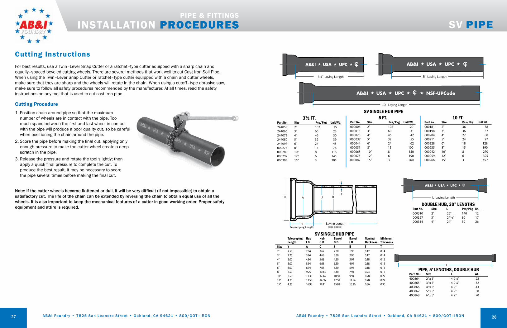
For best results, use a Twin–Lever Snap Cutter or a ratchet–type cutter equipped with a sharp chain and equally–spaced beveled cutting wheels. There are several methods that work well to cut Cast Iron Soil Pipe. When using the Twin–Lever Snap Cutter or ratchet–type cutter equipped with a chain and cutter wheels, make sure that they are sharp and the wheels will rotate in the chain. When using a cutoff–type abrasive saw, make sure to follow all safety procedures recommended by the manufacturer. At all times, read the safety instructions on any tool that is used to cut cast iron pipe.
Cutting Procedure1. Position chain around pipe so that the maximum
number of wheels are in contact with the pipe. Too much space between the first and last wheel in contact with the pipe will produce a poor quality cut, so be careful when positioning the chain around the pipe.
2. Score the pipe before making the final cut, applying only enough pressure to make the cutter wheel create a deep scratch in the pipe.
3. Release the pressure and rotate the tool slightly; then apply a quick final pressure to complete the cut. To produce the best result, it may be necessary to score the pipe several times before making the final cut.
Note: If the cutter wheels become flattened or dull, it will be very difficult (if not impossible) to obtain a satisfactory cut. The life of the chain can be extended by reversing the chain to obtain equal use of all the wheels. It is also important to keep the mechanical features of a cutter in good working order. Proper safety equipment and attire is required.
Cutting Instructions
27
AB&I ★ USA ★ UPC ★
AB&I ★ USA ★ UPC ★ NSF-UPCode★
AB&I ★ USA ★ UPC ★
AB&I ★ USA ★ UPC ★
L Laying Length
DOUBLE HUB, 30” LENGTHSPart No. Size L Pcs/Pkg Wt.000310 2” 25” 140 12000327 3” 24½” 80 17000334 4” 24” 50 26
AB&I ★ USA ★ UPC ★
AB&I ★ USA ★ UPC ★ NSF-UPCode★
AB&I ★ USA ★ UPC ★
AB&I ★ USA ★ UPC ★
(see above)Telescoping Length
SV SINGLE HUB PIPE Telescoping Hub Hub Barrel Barrel Nominal Minimum Length I.D. O.D. O.D. I.D. Thickness Thickness Size Y A C J B T T 2” 2.50 2.94 3.62 2.30 1.96 0.17 0.14 3” 2.75 3.94 4.68 3.30 2.96 0.17 0.14 4” 3.00 4.94 5.68 4.30 3.94 0.18 0.15 5” 3.00 5.94 6.68 5.30 4.94 0.18 0.15 6” 3.00 6.94 7.68 6.30 5.94 0.18 0.15 8” 3.50 9.25 10.13 8.40 7.94 0.23 0.17 10” 3.50 11.38 12.44 10.50 9.94 0.28 0.22 12” 4.25 13.50 14.56 12.50 11.94 0.28 0.22 15” 4.25 16.95 18.11 15.88 15.16 0.36 0.30
Laying LengthY
C A J BT
PIPE, 5’ LENGTHS, DOUBLE HUBPart No. Size L Wt.400864 2” x 5’ 4’ 9½” 22 400865 3” x 5’ 4’ 9¼” 32 400866 4” x 5’ 4’ 9” 43 400867 5” x 5’ 4’ 9” 58 400868 6” x 5’ 4’ 9” 70
L
AB&I ★ USA ★ UPC ★
AB&I ★ USA ★ UPC ★ NSF-UPCode★
AB&I ★ USA ★ UPC ★
AB&I ★ USA ★ UPC ★
AB&I ★ USA ★ UPC ★
AB&I ★ USA ★ UPC ★ NSF-UPCode★
AB&I ★ USA ★ UPC ★
AB&I ★ USA ★ UPC ★
AB&I ★ USA ★ UPC ★
AB&I ★ USA ★ UPC ★ NSF-UPCode★
AB&I ★ USA ★ UPC ★
AB&I ★ USA ★ UPC ★
5’ Laying Length
10’ Laying Length
SV SINGLE HUB PIPE3½ FT.
Part No. Size Pcs/Pkg Unit Wt.244059 2” 102 15 244066 3” 60 23 244073 4” 46 30 244080 5” 32 39 244097 6” 24 45 000273 8” 15 78 000280 10” 8 116 000297 12” 6 145 000303 15” 3 205
5 FT.Part No. Size Pcs/Pkg Unit Wt.000006 2” 102 20000013 3” 60 31000020 4” 46 42000037 5” 32 55000044 6” 24 62000051 8” 15 100 000068 10” 8 150000075 12” 6 190000082 15” 3 260
10 FT.Part No. Size Pcs/Pkg Unit Wt. 000181 2” 36 38000198 3” 36 57000204 4” 27 80000211 5” 24 97000228 6” 18 128000235 8” 15 190000242 10” 8 270000259 12” 6 325000266 15” 3 497
3½’ Laying Length
SV PIPE
28
AB&I Foundry • 7825 San Leandro Street • Oakland, CA 94621 • 800/GOT–IRON AB&I Foundry • 7825 San Leandro Street • Oakland, CA 94621 • 800/GOT–IRON
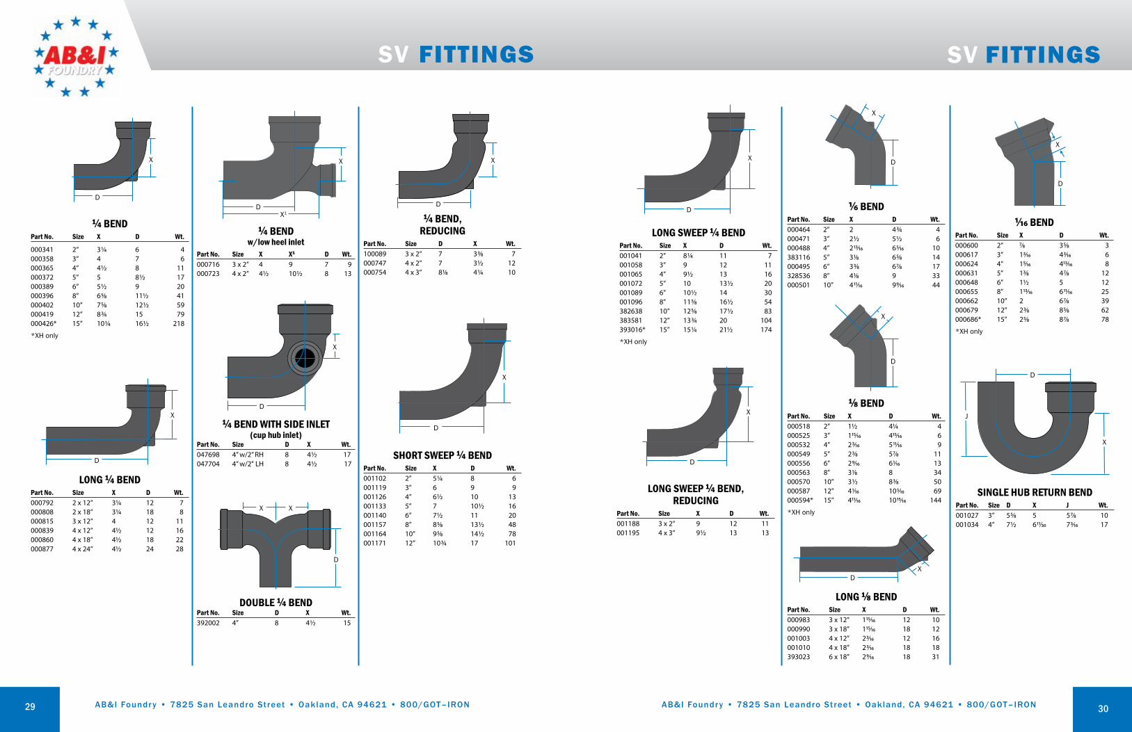
1/6 BENDPart No. Size X D Wt.000464 2” 2 4¾ 4000471 3” 2½ 5½ 6000488 4” 213/16 65/16 10383116 5” 31/8 65/8 14000495 6” 33/8 67/8 17328536 8” 41/8 9 33000501 10” 411/16 99/16 44
D
X
⅛ BENDPart No. Size X D Wt.000518 2” 1½ 4¼ 4000525 3” 115/16 415/16 6000532 4” 23/16 511/16 9000549 5” 23/8 57/8 11000556 6” 29/16 61/16 13000563 8” 31/8 8 34000570 10” 3½ 83/8 50000587 12” 41/16 105/16 69000594* 15” 411/16 1015/16 144
*XH only
D
X
X
X1D
¼ BEND w/low heel inlet
Part No. Size X X1 D Wt.000716 3 x 2” 4 9 7 9000723 4 x 2” 4½ 10½ 8 13
X1D
1/16 BENDPart No. Size X D Wt.000600 2” 7/8 35/8 3000617 3” 13/16 43/16 6000624 4” 15/16 413/16 8000631 5” 13/8 47/8 12000648 6” 1½ 5 12000655 8” 113/16 611/16 25000662 10” 2 67/8 39000679 12” 23/8 85/8 62000686* 15” 25/8 87/8 78
*XH only
X
D
X
¼ BEND WITH SIDE INLET(cup hub inlet)
Part No. Size D X Wt.047698 4” w/2” RH 8 4½ 17047704 4” w/2" LH 8 4½ 17
D
DOUBLE ¼ BENDPart No. Size D X Wt.392002 4” 8 4½ 15
D
XX
¼ BENDPart No. Size X D Wt.
000341 2” 3¼ 6 4000358 3” 4 7 6000365 4” 4½ 8 11000372 5” 5 8½ 17000389 6” 5½ 9 20000396 8” 65/8 11½ 41000402 10” 75/8 12½ 59000419 12” 8¾ 15 79000426* 15” 10¼ 16½ 218
*XH only
D
X
SV FITTINGS
29
LONG ¼ BENDPart No. Size X D Wt.000792 2 x 12” 3¼ 12 7000808 2 x 18” 3¼ 18 8000815 3 x 12” 4 12 11000839 4 x 12” 4½ 12 16000860 4 x 18” 4½ 18 22000877 4 x 24” 4½ 24 28
D
X
LONG ⅛ BENDPart No. Size X D Wt.000983 3 x 12” 115/16 12 10000990 3 x 18” 115/16 18 12001003 4 x 12” 23/16 12 16001010 4 x 18” 23/16 18 18393023 6 x 18” 29/ 16 18 31
DX
LONG SWEEP ¼ BEND Part No. Size X D Wt.001041 2” 8¼ 11 7001058 3” 9 12 11001065 4” 9½ 13 16001072 5” 10 13½ 20001089 6” 10½ 14 30001096 8” 115/8 16½ 54382638 10” 125/8 17½ 83383581 12” 13¾ 20 104 393016* 15” 15¼ 21½ 174
*XH only
X
D
LONG SWEEP ¼ BEND, REDUCING
Part No. Size X D Wt.001188 3 x 2” 9 12 11001195 4 x 3” 9½ 13 13
D
X
D
J
X
SINGLE HUB RETURN BENDPart No. Size D X J Wt.001027 3” 55/8 5 57/8 10 001034 4” 7½ 611/30 73/16 17
SV FITTINGS
D
X
SHORT SWEEP ¼ BENDPart No. Size X D Wt.001102 2” 5¼ 8 6001119 3” 6 9 9001126 4” 6½ 10 13001133 5” 7 10½ 16001140 6” 7½ 11 20001157 8” 85/8 13½ 48001164 10” 95/8 14½ 78001171 12” 10¾ 17 101
¼ BEND, REDUCING
Part No. Size D X Wt.100089 3 x 2” 7 33/8 7 000747 4 x 2” 7 3½ 12 000754 4 x 3” 81/8 4¼ 10
D
X
30
AB&I Foundry • 7825 San Leandro Street • Oakland, CA 94621 • 800/GOT–IRON AB&I Foundry • 7825 San Leandro Street • Oakland, CA 94621 • 800/GOT–IRON
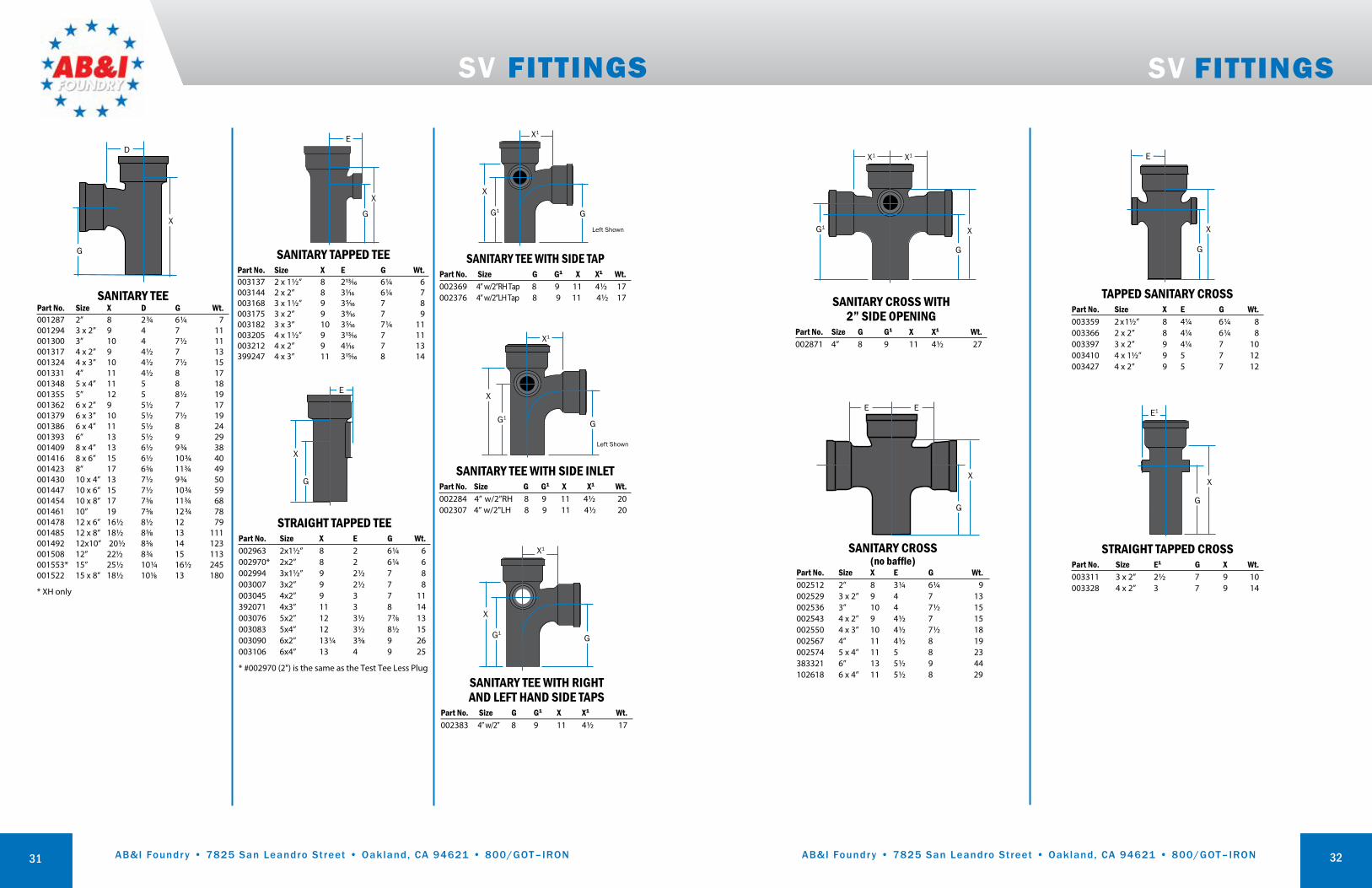
STRAIGHT TAPPED TEEPart No. Size X E G Wt.002963 2x1½” 8 2 6¼ 6002970* 2x2” 8 2 6¼ 6002994 3x1½” 9 2½ 7 8003007 3x2” 9 2½ 7 8003045 4x2” 9 3 7 11392071 4x3” 11 3 8 14003076 5x2” 12 3½ 77/8 13003083 5x4” 12 3½ 8½ 15003090 6x2” 13¼ 35/8 9 26003106 6x4” 13 4 9 25
* #002970 (2") is the same as the Test Tee Less Plug
G
X
E
SV FITTINGS
SANITARY TEEPart No. Size X D G Wt.001287 2” 8 2¾ 6¼ 7001294 3 x 2” 9 4 7 11001300 3” 10 4 7½ 11001317 4 x 2” 9 4½ 7 13001324 4 x 3” 10 4½ 7½ 15001331 4” 11 4½ 8 17001348 5 x 4” 11 5 8 18001355 5” 12 5 8½ 19001362 6 x 2” 9 5½ 7 17001379 6 x 3” 10 5½ 7½ 19001386 6 x 4” 11 5½ 8 24001393 6” 13 5½ 9 29001409 8 x 4” 13 6½ 9¾ 38001416 8 x 6” 15 6½ 10¾ 40001423 8” 17 65/8 11¾ 49001430 10 x 4” 13 7½ 9¾ 50001447 10 x 6” 15 7½ 10¾ 59001454 10 x 8” 17 75/8 11¾ 68001461 10” 19 75/8 12¾ 78001478 12 x 6” 16½ 8½ 12 79001485 12 x 8” 18½ 85/8 13 111001492 12x10” 20½ 85/8 14 123001508 12” 22½ 8¾ 15 113001553* 15” 25½ 10¼ 16½ 245001522 15 x 8” 18½ 101/8 13 180
* XH only
G
D
X
SANITARY TEE WITH RIGHT AND LEFT HAND SIDE TAPS
Part No. Size G G1 X X1 Wt.002383 4” w/2” 8 9 11 4½ 17
G1G
X1
X
SANITARY TEE WITH SIDE TAPPart No. Size G G1 X X1 Wt.002369 4” w/2”RH Tap 8 9 11 4½ 17002376 4” w/2”LH Tap 8 9 11 4½ 17
G1 G
X1
X
Left Shown
SANITARY TEE WITH SIDE INLETPart No. Size G G1 X X1 Wt.002284 4” w/2”RH 8 9 11 4½ 20002307 4” w/2"LH 8 9 11 4½ 20
G1G
X1
X
Left Shown
31
SV FITTINGS
STRAIGHT TAPPED CROSSPart No. Size E1 G X Wt.003311 3 x 2” 2½ 7 9 10003328 4 x 2” 3 7 9 14
G
X
E1
TAPPED SANITARY CROSSPart No. Size X E G Wt.003359 2 x 1½” 8 4¼ 6¼ 8003366 2 x 2” 8 4¼ 6¼ 8003397 3 x 2” 9 4¼ 7 10003410 4 x 1½” 9 5 7 12003427 4 x 2” 9 5 7 12
G
X
E
SANITARY TAPPED TEEPart No. Size X E G Wt.003137 2 x 1½” 8 213/16 6¼ 6003144 2 x 2” 8 31/16 6¼ 7003168 3 x 1½” 9 35/16 7 8003175 3 x 2” 9 39/16 7 9003182 3 x 3” 10 35/16 7¼ 11003205 4 x 1½” 9 313/16 7 11003212 4 x 2” 9 41/16 7 13399247 4 x 3” 11 315/16 8 14
G
E
X
SANITARY CROSS(no baffle)
Part No. Size X E G Wt.002512 2” 8 3¼ 6¼ 9002529 3 x 2” 9 4 7 13002536 3” 10 4 7½ 15002543 4 x 2” 9 4½ 7 15002550 4 x 3” 10 4½ 7½ 18002567 4” 11 4½ 8 19002574 5 x 4” 11 5 8 23383321 6” 13 5½ 9 44102618 6 x 4” 11 5½ 8 29
G
X
E E
G1
X1
G
X
X1
SANITARY CROSS WITH 2” SIDE OPENING
Part No. Size G G1 X X1 Wt.002871 4” 8 9 11 4½ 27
32

AB&I Foundry • 7825 San Leandro Street • Oakland, CA 94621 • 800/GOT–IRON AB&I Foundry • 7825 San Leandro Street • Oakland, CA 94621 • 800/GOT–IRON
COMBINATION WYE & ⅛ BENDPart No. Size G H X X1 Wt.001966 2” 4 73/8 8 47/8 8001973 3 x 2” 43/16 83/16 9 5¾ 12001980 3” 5 101/16 10½ 7 14001997 4 x 2” 311/16 83/16 9 6¼ 12002000 4 x 3” 4½ 101/16 10½ 7½ 18002017 4” 5¼ 121/16 12 9 22002024 5 x 2” 33/8 83/8 9 6¾ 15383123 5 x 3” 4 101/16 10½ 8 22002031 5 x 4” 4¼ 75/16 12 9½ 24002048 5” 5½ 119/16 13½ 11 30002055 6 x 2” 211/16 83/16 9 7¼ 17002062 6 x 3” 31/8 911/16 10¼ 8½ 19002079 6 x 4” 4¼ 121/16 12 10 23388258 6 x 5” 51/16 143/16 13½ 11½ 40002086 6” 5¾ 161/16 15 127/8 45383611 8 x 2” 31/8 95/8 10½ 8¼ 34002093 8 x 4” 4¾ 131/16 13½ 11 44384748 8 x 5” 5½ 155/8 15 12½ 50002109 8 x 6” 65/16 175/8 16½ 137/8 60002116 8” 711/16 219/16 19½ 17 85
H
G
X
X1
DOUBLE WYEPart No. Size X X1 G Wt.002598 2” 8 4 4 9002604 3 x 2” 9 5 43/16 13002611 3” 10½ 5½ 5 16002628 4 x 2” 9 5¾ 35/8 15002635 4 x 3” 10½ 6¼ 47/16 19002642 4” 12 9¼ 5¼ 23392026 5” 13½ 8 5½ 27 387855 6 x 3” 10½ 7 35/8 23002659 6 x 4” 12 8¼ 43/16 32002666 6” 15 9¼ 5¾ 45002673 8 x 4” 13½ 9½ 4¾ 50002680 8 x 6” 16½ 10½ 65/16 64002697 8” 19½ 1113/16 711/16 90383086 10 x 6” 19½ 12½ 6½ 81002703 10 x 8” 19½ 137/16 6½ 114002710 10” 22½ 14½ 8 120002727 12 x 8” 21 14¾ 71/16 136002734 12” 27 167/8 101/8 175002741* 15” 31½ 20¾ 10¾ 354
* XH only
G
XX1
COMBINATION WYE & ⅛ BEND WITH SIDE INLET
Part No. Size G H X X1 Wt.002413 4” w/2” RH 10 121/16 12 9 28002420 4” w/2” LH 10 121/16 12 9 29
G
XH
X
SV FITTINGS
WYEPart No. Size X X1 G Wt.001560 2” 8 4 4 8001577 3 x 2” 9 5 43/16 9001584 3” 10½ 5½ 5 14001591 4 x 2” 9 5¾ 35/8 13001607 4 x 3” 10½ 6¼ 47/16 18001614 4” 12 6¾ 5¼ 18001621 5 x 2” 9 6½ 31/8 14001638 5 x 3” 10½ 7 37/8 17001645 5 x 4” 12 7½ 411/16 19001652 5” 13½ 8 5½ 23001669 6 x 2” 9 7¼ 29/16 17001676 6 x 3” 10½ 7¾ 33/8 17001683 6 x 4” 12 8¼ 43/16 21001690 6 x 5” 13¼ 8¾ 415/16 31001706 6” 15 9¼ 5¾ 36383482 8x2” 10½ 8½ 31/8 31387848 8 x 3” 12 9 315/16 33001713 8 x 4” 13½ 9½ 4¾ 45001720 8 x 5” 15 10 5½ 46001737 8 x 6” 16½ 10½ 65/16 53001744 8” 19½ 1113/16 711/16 65001751 10 x 3” 12 10¾ 2¾ 56001768 10 x 4” 13½ 111/8 39/16 64001775 10 x 5” 15 115/8 45/16 65001782 10 x 6” 16½ 12½ 51/8 76001799 10 x 8” 19½ 137/16 6½ 85001805 10” 22½ 14½ 8 107001812 12 x 4” 15 127/16 41/8 76001829 12 x 5” 16½ 1215/16 47/8 75001836 12 x 6” 18 137/16 511/16 84001843 12 x 8” 21 14¾ 71/16 110001850 12 x 10” 24 1513/16 89/16 159001867 12” 27 167/8 101/8 189001874 15 x 4” 15¼ 15 2½ 138001881 15 x 6” 18 15¾ 4 171001898 15 x 8” 21 171/16 53/8 207001904 15 x 10” 24 181/8 67/8 213001911 15 x 12” 27 193/16 87/16 242001928* 15” 31½ 20¾ 10¾ 333
*XH only
G
X1
X
33
DOUBLE COMBINATION WYE & ⅛ BENDPart No. Size X H X1 F G Wt.002758 2” 8 33/8 47/8 73/8 4 12002765 3x2” 9 4 5¾ 83/16 43/16 14002772 3” 10½ 51/16 7 101/16 5 20002789 4x2” 9 4½ 6¼ 83/16 311/16 16002796 4x3” 10½ 59/16 7½ 101/16 4½ 23002802 4” 12 613/16 9 121/16 5¼ 34101925 5x4” 12 75/16 9½ 119/16 4¼ 31002819 6x4” 12 713/16 10 121/16 4¼ 52002826 6” 15 105/16 127/8 161/16 5¾ 80
G
HX
F
X1X1
SV FITTINGS
WYE WITH RIGHT HAND SIDE INLET(cup hub inlet)
Part No. Size G G1 X X1 Wt.002390 4” w/2” 5¼ 10 12 6¾ 18
G
G1
XX1
2”Inlet
45°
DOUBLE WYE WITH 2” SIDE OPENING(cup hub inlet)
Part No. Size G H X X1 Wt.002932 4” 5¼ 10 12 6¾ 32
XH
G
X1
45°
WYE WITH LEFT HAND SIDE INLET(cup hub inlet)
Part No. Size G G1 X X1 Wt.002406 4” w/2” 5¼ 10 12 6¾ 18
G
G1
X X1
2”Inlet
45°
34

AB&I Foundry • 7825 San Leandro Street • Oakland, CA 94621 • 800/GOT–IRON AB&I Foundry • 7825 San Leandro Street • Oakland, CA 94621 • 800/GOT–IRON
TWO-WAY DOUBLE CLEANOUT Part No. Size X E G J Wt.003519 4” 135/8 7½ 6½ 67/16 29003533 6 x 4” 135/8 8½ 6½ 67/16 35
G
X
J
E
TWO-WAY CLEANOUT (Memphis code)
Part No. Size X E G Wt.003465 4” 221/8 93/8 12¾ 35
X
E
G
INCREASERPart No. Size X Wt.045939 2 x 4” 9 10003809 3 x 4” 9 9 003816 4 x 5” 9 12 003823 4 x 6” 9 16 003830 4 x 8” 12 25277248 5 x 6” 9½ 13003847 6 x 8” 12 24384724 8 x 10” 12 44003854 10 x 12” 12 60003861 12 x 15” 12 95
X
LONG PLAIN INCREASERPart No. Size X Wt.003885 3 x 4" 24 14003892 4 x 5" 30 24
X
LONG TAPPED INCREASERPart No. Size X Wt.003939 2 x 4" 24 15
X
SV FITTINGS
REDUCERPart No. Size X Wt.003588 3 x 2” 4¾ 5003595 4 x 2” 5 6003601 4 x 3” 5 7383598 5 x 2” 5 6383604 5 x 3” 5 7003618 5 x 4” 5 8003625 6 x 2” 5 9003632 6 x 3” 5 7003649 6 x 4” 5 11003656 6 x 5” 5 9003663 8 x 4” 6 13003670 8 x 5” 6 14003687 8 x 6” 6 17003694 10 x 4” 6 20383369 10 x 5” 6 21003700 10 x 6” 6 24003717 10 x 8” 6 27003724 12 x 4” 6½ 32003731 12 x 6” 6½ 34003748 12 x 8” 6½ 37003755 12 x 10” 6½ 38003762 15 x 6” 6½ 52003779 15 x 8” 6½ 50003786 15 x 10” 6½ 56003793 15 x 12” 6½ 65
X
X
DOUBLE HUB FITTING Part No. Size X Wt.003960 2” 1 4003977 3” 1 6003984 4” 1 8003991 6” 1 11384755 8” 1½ 23004004 10” 1½ 37384762 12” 1½ 47004011* 15” 1½ 87
*XH only
35
“P” TRAP W/ ½” HEEL TAPPart No. Size X J A Wt.004813 2” 9½ 4 3 8004820 3” 12 5½ 3½ 13004837 4” 14 6½ 3½ 18
A
X
J
SV FITTINGS
“P” TRAPPart No. Size X J Wt.004486 2” 9½ 4 6004493 3” 12 5½ 12004509 4” 14 6½ 18004516 5” 15½ 7½ 23004523 6” 17 8½ 33004530 8” 221/16 11½ 87004547 10” 25 143/8 113
X
J
RUNNING TRAP W/SINGLE HUB VENT
Part No. Size (Vent) X X1 J Wt.004615 3” (3) 15 2½ 5½ 16004622 4” (4) 17½ 3 6½ 28004639 5” (4) 19½ 3½ 7½ 40004646 6” (4) 21½ 4 8½ 46 004660 8” (6) 275/8 5¾ 11 110004677 10" (8) 315/8 6¼ - 201004684 12" (10) 38¾ 7¼ - 295004691 15" (12) 45¾ 8¾ - 560
X
J
X1
RUNNING TRAP W/DOUBLE HUB VENT
Part No. Size (Vent) X X1 C J Wt.004707 3“ (3-3) 15 2½ 5 5½ 23004714 4” (4-4) 17½ 3 6 6½ 37004738 5” (4-4) 19½ 3½ 7 7½ 47004721 5x4” (4-4) 19½ 3½ 7 7½ 43004745 6“ (4-4) 21½ 4 8 8½ 54004752 6” (6-6) 21½ 4 8 8½ 62053880 8” (4-4) 21½ 4 8 8½ 99004769 8” (6-6) 275/8 5¼ 10 11 100004776 10” (8-8) 315/8 6¼ 12 13 187004783 12” (10-10) 38¾ 7¼ 15 15 288004790 15” (12-12) 45¾ 8¾ 18½ 18½ 460
X
C
J
X1
DEEP SEAL “P” TRAPPart No. Size X J Wt.004844 2” 9½ 6 9004851 3” 12 7 18004868 4” 14 8 29382614 6” 17 9½ 41
X
J
RUNNING TRAPPart No. Size X C J Wt.004578 4” 17½ 6 6½ 19004585 6” 21½ 8 8½ 65
X
C
J
36
PIPE PLUG Part No. Size F Wt.004035 2” 3½ 1004042 3” 3¾ 2004059 4” 4 4004066 5” 4 6004073 6” 4 6004080 8” 4½ 11004097 10” 4½ 17004103 12” 5¼ 31004110* 15” 5¼ 51
*XH only
F
2-70 TEST TEE (SV less plug)
Part No. Pipe Size Tap Size B C Wt.024507 2” 2 8 6¼ 6024521 3” 3 101/8 73/8 10024545 4” 3½ 111/8 8 14024569* 4” 3½ 9 6¼ 10024583 4” 4 111/8 8 14024576* 4” 4 9 6¼ 10024606 5” 5 11 7 22024613 6” 6 13 8¾ 26024637 8” 8 163/8 11 47024668 10” 10 175/8 11 73
2-70 TEST TEE W/ TYPE A PLUGPart No. Pipe Size Tap Size B C Wt.024675 2” 2 8 6 6024699 3” 3 101/8 73/8 11024750 4” 3½ 111/8 8 18024712* 4” 3½ 9 6¼ 11024736* 4” 4 9 6¼ -024774 4” 4 111/8 7 15024798 5” 5 11 7 11024811 6” 6 13 8¾ 28024835 8” 8 163/8 11 51383079** 12” 8 18½ 13 -
* Short Laying Length ** Southern Raised Head
B
C

AB&I Foundry • 7825 San Leandro Street • Oakland, CA 94621 • 800/GOT–IRON AB&I Foundry • 7825 San Leandro Street • Oakland, CA 94621 • 800/GOT–IRON
2–11 STANDARD FERRULE (less plug)
Part No. Pipe Size Tap Size A Wt.023210 2” 1½ 3¼ 1023234 3” 2½ 3¾ 2023258 4” 3 3¼ 3023272 4” 3½ 4¼ 3023296 5” 4 4¼ 4023319 6” 5 4¼ 5023333 8” 6 4½ 11023357 10” 6 4½ 18023388 12” 6 5¼ 24023364* 15” 6 5¼ 45
*XH only
2–11 STANDARD FERRULE W/TYPE A PLUG
Part No. Pipe Size Tap Size A Wt.023395 2” 1½ 3½ 1023425 3” 2½ 3¾ 3023456 4” 3 3¼ 4023487 4” 3½ 4¼ 4023517 5” 4 4¼ 5023548 6” 5 4¼ 6023586 8” 6 4½ 13023609 10” 6 4½ 20023630 12” 6 5¼ 26023616* 15” 6 5¼ 47
*XH only
A
CLOSET BENDSPart No. Size Wt02896 4 x 4 x 14” 1102894 4 x 4 x 16” 1502898 4 x 4 x 18” 1302904 4 x 6 x 12” 1202908 4 x 6 x 15” 1502914 4 x 6 x 16” 1302912 4 x 6 x 18” 1602924 4 x 10 x 12” 1602932 4 x 10 x 15” 1702934 4 x 10 x 16” 1602936 4 x 10 x 18” 1902938 4 x 12 x 12” 1402940 4 x 12 x 14” 1802944 4 x 12 x 16” 1602946 4 x 12 x 18” 2102950 4 x 16 x 16” 2202954 4 x 18 x 18” 25
CLOSET BENDS (REDUCING)Part No. Size Wt.02832 4 x 3 x 6 x 12” 1002840 4 x 3 x 6 x 15” 1002844 4 x 3 x 6 x 18” 1302852 4 x 3 x 10 x 12” 1202860 4 x 3 x 10 x 15” 1602864 4 x 3 x 10 x 18” 1602866 4 x 3 x 12 x 12” 1602870 4 x 3 x 16 x 16” 1802872 4 x 3 x 18 x 18” 25
CLOSET BENDS REGULAR HUBPart No. Size Length Wt.026136 4” 12 14026146 4” 14 16026156 4” 16 16026167 4” 18 19
A
TAPPED CLOSET BEND WITH SOUTHERN CODE BRASS PLUG
Part No. Size A B Wt.005803 3½ x 4” 24 63/8 18
B
3½” Tap
SV FITTINGS
B
D
A
B
D
A
B
D
A
BA
D
2–252 CLOSET FLANGE(caulk joint application)
Part No. Size x Height A B D Wt.022848 4x1” 6¼ 7¼ 1 2022855 4x1½” 6¼ 7¼ 1½ 28003 4x2” 6¼ 7¼ 2 28013* 4x2” 63/8 7¼ 2 2.8022879 4x2½” 6¼ 7¼ 2½ 3022886 4x3” 6¼ 7¼ 3 48005 4x4” 6¼ 7¼ 4 5022930* 4x4” 61/8 7¼ 4 5022909 4x5” 6¼ 7¼ 5 68017 4x6” 6¼ 7¼ 6 68015 4x2”, 1” Offset 6 7 2 2.58018 4x4”, 2” Offset 6¼ 7¼ 4 4.5022947 4x3”, 3” Reducing 6¼ 7¼ 3 38007 4x2” 6¼ 7¼ 2 38011 4x4 x 4” 6¼ 7¼ 4 48019 4x3 x 2½” 6¼ 7¼ 2½ 3
*Portland Code, two ¼” taps on topNOTE: Adhesive lubricants are required for TY-SEAL and EZ-TITE gaskets in sizes 5 inch and larger diameters.
37
SV FITTINGS
TAPPED BATH VENT WYEPart No. Size A B C D Wt.005766 2” 41/16 51/64 3¼ 2½ 9
2” Tap
2” Tap
2” HubE
A
B
F
45°
TAPPED LONG SWEEP TEEPart No. Size A B C D Wt.005773 2 x 2” 5½ 3⅛ 4 5⅝ 7
A
BD
C
2” Tap
2” Tap
2” Hub
SANITARY TEE WITH CLEANOUT ON MAIN
Part No. Size IPS Tap G X X1 Wt.112822 4” 3½ 8 12⅛ 4½ 17
X
X
X
TAPPED WYEPart No. Size G X X1 Wt.003236 3 x 2” 4 9 6⅝ 11003243 4 x 1½” 5¼ 9 7⅞ 11003250 4 x 2” 5¼ 9 6⅞ 13
G
XX1
TAPPED DOUBLE WYEPart No. Size G X X1 Wt.003441 4 x 2” 5¼ 9 7⅞ 16
G
XX1
LONG SANITARY TAPPED TEEPart No. Size G X X1 Wt.380016 2 x 2 x 18” 16 18 31/6 9
E1
X
G
38
SISSION INSERTABLE JOINTPart No. Size A B C Wt.428336 2” 14 6 6 7124415 3” 16 8 6¾ 12124422 4” 14½ 7 6 13384731 5” 157/8 9 57/8 17383178 6” 163/16 8½ 6 21102717 8” 18 10 6¾ 37
B C
A
VENT CAP WITH SET SCREWPart No. Size Wt.014591 4” 3
TAPPED SPIGOTPart No. Size X Wt.111719 4 x 2” 4¼ 5
X

AB&I Foundry • 7825 San Leandro Street • Oakland, CA 94621 • 800/GOT–IRON AB&I Foundry • 7825 San Leandro Street • Oakland, CA 94621 • 800/GOT–IRON
SV FITTINGS
“P” TRAP WITH CLEANOUT RIGHT SIDE
Part No. Size X J B D Wt.384779 4” 14 6½ 20 11 20NOTE: 3½” IPS tap.
BX
D J
“P” TRAP WITH CLEANOUT LEFT SIDE
Part No. Size X J B D Wt.384786 4” 14 6½ 11 5½ 20NOTE: 3½” IPS tap.
B
J
X
D
VENT BYPASS WITH 2 TAPPED SIDESPart No. Size A B C D E F Wt.005780 2 x 2” 18 10 6½ 3¾ 3 5¼ 12
E
CB
A
F
D
SV–458 VENTED CLOSET TEE WITH 2” TOP VENT AND 2” EXTENDED SIDE INLET, RIGHT HAND OR LEFT HANDPart No. Size A B C D E Wt.005575 4x4x2x2x4”RH 11 4½ 53/16 49/16 43/16 37005582 4x4x2x2x4”LH 11 4½ 53/16 49/16 43/16 38
E
B
A
C D
3¾”
IllustrationShows
Right Hand
45°
SV–459D VENTED CLOSET CROSS W/ 2” TOP VENT AND 2” EXTENDED SIDE INLET
Part No. Size A B C Wt.005599 4x4x2x2x4” 11 6¼ 4¾ 47
C
A
B
Not a baffled fitting
39
DOUBLE SINK STACK–770CPart No. Size A B C D E Wt.005827 3x2” 15½ 4½ 6⅝ 4½ 5¾ 18005834 4x2” 15½ 5¾ 7⅛ 4½ — 22
BC
D
E3” Hub
(SV)
2” Tap
2” Tap
2” Hub(SV)
4¾”
D
SV FITTINGS
SV 973R RIGHT HAND STARTER FITTING WITH 4” TAPAND 2” TAPPED “A” SIDE INLET
Part No. Size Inlet A B C D E F X Wt.107163 4” 6½ 6½ 6½ 4 41/16 4 4 25 35107170 4” 9½ 9½ 6½ 4 41/16 4 4 25 35
SV 973L LEFT HAND STARTER FITTING WITH 4” TAPAND 2” TAPPED “A” SIDE INLET
Part No. Size Inlet A B C D E F X Wt.107194 4” 6½ 6½ 6½ 4 4 4 4 25 39107217 4” 9½ 9½ 6½ 4 4 4 4 25 39
A
X
2” Tap
4” SV
4” NPT
2” SV
2” Tap
Support Bar
A
3⅜”
5/16 -18 UNC¾ FULL THD(2) HOLES 180° APART
⅜ -16 UNC-28FULL THD(3) HOLES 120° APART REF
BC
D E F
A
X
2” Tap 2”
Tap
2” SV
4” NPT
4” SVSupport Bar
A
5/16-18 UNC¾ FULL THD(2) HOLES 180° APART
⅜-16 UNC-28FULL THD(3) HOLES 120° APART REF
BC
D E F2⅞” 3⅜”
SV 975 DOUBLE STARTER FITTING WITH 4” TAPAND 2” TAPPED “A” SIDE INLET
Part No. Size A B C D E F X Wt.107255 4” 9½ 6½ 4 4 4 41/16 25 43
A
X
4”NPT 2”
Tap
2” SV
Baffle
4” SVSupport Bar
B
BCC
D E F⅜-16 UNC-28FULL THD(3) HOLES 120°APART REF
5/16-18 UNC¾ FULL THD
(2) HOLES 180° APART
40
6½” Tap

AB&I Foundry • 7825 San Leandro Street • Oakland, CA 94621 • 800/GOT–IRON AB&I Foundry • 7825 San Leandro Street • Oakland, CA 94621 • 800/GOT–IRON
SV FITTINGS
SV 974R RIGHT HAND STARTER FITTING WITH 4” HUB Part No. Size A B C D E X Wt.107231 4” with A inlets 6½ 0 6½ 41/16 4 25 39011094 4” with A & B inlets 6½ 18 6½ 41/16 4 25 46
A
X
2” Tap
4” SV
4” NPT
2” SV
2” Tap
Support Bar
A
5/16-18 UNC¾ FULL THD(2) HOLES 180° APART
⅜-16 UNC-28FULL THD(3) HOLES
120° APART REF
BC
D E F
A
X
2” Tap 2” Tap
2” SV
2” Tap
Support Bar
A
D C
45°
Ø 3¾
Finished Floor
41/6
SV 974L LEFT HAND STARTER FITTING WITH 4” HUB Part No. Size A B C D E F X Wt.107248 4” with A inlets 6½ 6½ 6½ 4 4 41/16 25 39011093 4” with A & B inlets 6½ 18 6½ 4 - - 25 44
SV 976 DOUBLE STARTER FITTING WITH 4” HUB AND 2” TAPPED “A” SIDE INLET
Part No. Size A B C D E X Wt.107262 4” with A inlets 6½ 6½ 6½ 4 4 25 51011095 4” with A & B inlets 6½ 18 6½ 4 4 25 59
A
B
X2” Tap2” Tap
2” Tap
A
CD
Finished Floor
41/6
A
X
2” Tap 2”
Tap
2” SV
4” SVHub
4” SVSupport Bar
A
5/16-18 UNC¾ FULL THD
(2) HOLES 180° APART
⅜-16 UNC-28FULL THD(3) HOLES 120° APART REF
C
D
A
X
2” Tap4”
NPT 2” Tap
2” SV
Baffle
4” SVSupport Bar
A
⅜-16 UNC-28FULL THD(3) HOLES 120° APART REF
BCC
D E F
A
B
X2” Tap
2” Tap2” Tap
A
CD
Finished Floor
BaffleE
45°
B
5/16-18 UNC¾ FULL THD
(2) HOLES 180° APART
41
TRIM PACKAGE FOR
STARTER FITTINGS
support leg
DB
A
C
3”17”12
4½
7¼B.C.½ - 13 UNC - 2B(4) places
⅝ - 11 UNC - 2B(5) places
6¾B.C.4½
7½67/32
3⅜3¾
20
⅜
½⅜
3
⅝
1
⅞
⅜
⅜
¾
19⅞4¼
2⅛
30˚
30˚
4½
3⅛
⅝
⅝
⅝
1¼
9/16 ¾
2⅜
⅝⅞
1½
1
11/32
1¼
1 17/16
511/16
5/16
67/16
115/16
23/162⅛
5⅝
5⅝
17¾
15/32TYP
3° TYP
23/32
12⅜
3⅛
4½6
1115/16
45/16
R 213/16R 311/16
R ⅞
19/16
1
(6) p
lace
s
front viewside view
front view side view
EZS 22 EXTENDED LEG(left or right)
EZS 22 SUPPORT LEG
42
4 41/16

AB&I Foundry • 7825 San Leandro Street • Oakland, CA 94621 • 800/GOT–IRON AB&I Foundry • 7825 San Leandro Street • Oakland, CA 94621 • 800/GOT–IRON
TRIM PACKAGE FOR
STARTER FITTINGS
1 — 4” PVC Sch. 80 NIPPLE with TEST CAP1 — BOWL GASKET4 — ⅝” X 12” RODS4 — ⅝” CHROME CAP NUTS8 — ⅝” JAM NUTS4 — ⅝” FLAT WASHERS4 — ⅝” FIBER WASHERS3 — ⅜” X 1½” BOLTS FOR FACEPLATE3 — ⅜” FLAT WASHERS4 — ⅝” STAR WASHERS
1 — 4” PVC Sch. 80 NIPPLE with TEST CAP1 — BOWL GASKET2 — 5/16” X 12” RODS2 — 5/16” HEX NUTS2 — 5/16” FLAT WASHERS2 — 5/16” CAP NUTS
1. IDENTIFY THE MAJOR COMPONENTS OF THE EZS 24 TRIM PACKAGE AND EZS 22 SUPPORT FRAME.
2. SECURE EZS 22 SUPPORT FRAME TO INSTALLED STARTER FITTING USING ⅜” X 1½” BOLTS AND ⅜” FLAT WASHERS.
3. SECURE RIGHT AND LEFT LEGS TO THE EZS 22 FACEPLATE USING ½” X 1¼” BOLTS AND ½” FLAT WASHERS IN POSITION SHOWN TO THE RIGHT.
4. ADJUST ASSEMBLY TO THE DESIRED HEIGHT. LEVEL AND ALIGN THE ASSEMBLY.
5. SECURE THE FEET OF THE EZS 22 SUPPORT FRAME TO THE FLOOR USING THE ½” X 1¼” BOLTS SUPPLIED.
6. SECURE SUPPORT LEG. FOR DOUBLE STARTER FITTINGS, THE SUPPORT LEG IS NOT REQUIRED.
7. SECURE ⅝” X 12” EZS 24 THREAD RODS TO FACEPLATE ACCORDING TO EZS 22 FACEPLATE.
8. INSTALL EZS 24 THREADED NIPPLE TO THE EZS 700 OR EZS 800 FITTING.
EZS 24TRIM PACKAGE, WALL-HUNG BACK-OUTLET ASSEMBLY
(to be used with PART NO. EZS 22 support frame assembly)
EZS 23TRIM PACKAGE, FLOOR-MOUNTED BACK-OUTLET ASSEMBLY
(note: not to be used with PART NO. EZS 22 support frame assembly)
EZS 22 AND EZS 24 INSTALLATION INSTRUCTIONS
43
TY–SEAL LUBRICANTPart No. Size Wt.005117 Quart 2.5
• An excellent water-soluble joint compound. TY-SEAL LUBRICANT has demonstrated its efficiency in millions of joints.
• Quick and easy to use under all conditions… Even under water!
• Available in quarts, gallons and 25 pound pails.
LUBRI/FAST® LUBRICANTPart No. Size Wt.005110 Quart 2.5
LUBRI/FAST
• The unique LUBRI/FAST ® formula makes joining TY-SEAL gaskets easier and faster because it’s so slick! Applied as a liquid, LUBRI/FAST® actually reduces joining forces required; then it literally “fastens” the joint.
• LUBRI/FAST ® is applied with an ordinary paint brush. It may be used for joining all pipe and fittings, and is required for joining all larger diameters 5” through 15”.
EZ–TITE Wt. Ea. Carton Pallet Part No. Size Lbs. Quantity Wt. Quantity Wt.004950 2” 0.3 60 18 2880 900004967 3” 0.4 40 16 1600 675004974 4” 0.6 40 24 1280 805004981 5” 1.2 30 35 600 735004998 6” 1.4 30 40 600 835
TY–TOOLS Joins Pipe Approx. Part No. Description Size Wt.005223 4” w/ 4 x 2 & 4 x 3 adapter 2”, 3”, 4” 21005438 6" w/ 6 x 4 adapter 4”, 6” 29005580 8" w/ 8 x 6 adapter 6”, 8” 40
TY–SEAL Wt. Ea. Carton Pallet Part No. Size Lbs. Quantity Wt. Quantity Wt.004875 2” 0.3 60 18 2880 900004882 3” 0.4 40 16 1600 675004899 4” 0.6 40 24 1280 805004905 5” 1.2 30 35 600 735004912 6” 1.4 30 40 600 835004929 8” 1.6 20 30 320 151004936 10” 2.0 10 18 270 520004943 12” 2.5 10 22 270 630014959 15” 3.8 10 38 120 490
SV PRODUCTS
44
AB&I Foundry • 7825 San Leandro Street • Oakland, CA 94621 • 800/GOT–IRON AB&I Foundry • 7825 San Leandro Street • Oakland, CA 94621 • 800/GOT–IRON
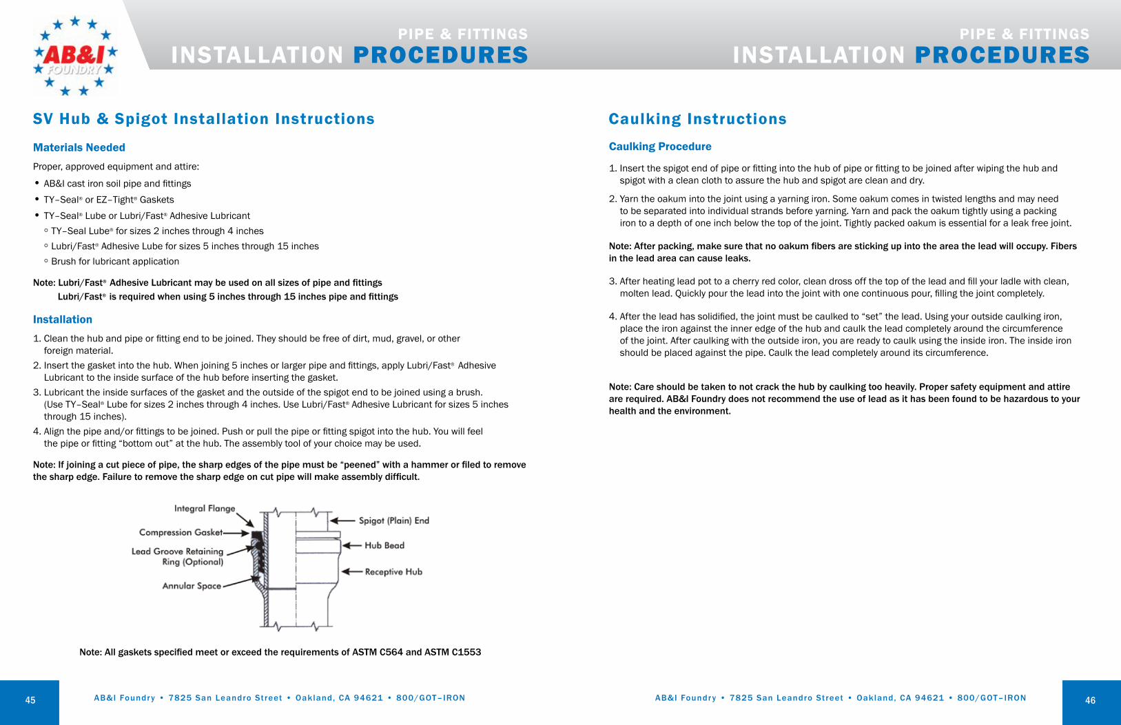
Materials NeededProper, approved equipment and attire:
• AB&I cast iron soil pipe and fittings• TY–Seal® or EZ–Tight® Gaskets• TY–Seal® Lube or Lubri/Fast® Adhesive Lubricant
◦ TY–Seal Lube® for sizes 2 inches through 4 inches◦ Lubri/Fast® Adhesive Lube for sizes 5 inches through 15 inches◦ Brush for lubricant application
Note: Lubri/Fast® Adhesive Lubricant may be used on all sizes of pipe and fittingsLubri/Fast® is required when using 5 inches through 15 inches pipe and fittings
Installation1. Clean the hub and pipe or fitting end to be joined. They should be free of dirt, mud, gravel, or other
foreign material.2. Insert the gasket into the hub. When joining 5 inches or larger pipe and fittings, apply Lubri/Fast® Adhesive
Lubricant to the inside surface of the hub before inserting the gasket.3. Lubricant the inside surfaces of the gasket and the outside of the spigot end to be joined using a brush.
(Use TY–Seal® Lube for sizes 2 inches through 4 inches. Use Lubri/Fast® Adhesive Lubricant for sizes 5 inches through 15 inches).
4. Align the pipe and/or fittings to be joined. Push or pull the pipe or fitting spigot into the hub. You will feel the pipe or fitting “bottom out” at the hub. The assembly tool of your choice may be used.
Note: If joining a cut piece of pipe, the sharp edges of the pipe must be “peened” with a hammer or filed to remove the sharp edge. Failure to remove the sharp edge on cut pipe will make assembly difficult.
PIPE & FITTINGS INSTALLATION PROCEDURES
SV Hub & Spigot Installation Instructions
Note: All gaskets specified meet or exceed the requirements of ASTM C564 and ASTM C1553
45
PIPE & FITTINGS INSTALLATION PROCEDURES
Caulking Procedure
1. Insert the spigot end of pipe or fitting into the hub of pipe or fitting to be joined after wiping the hub and spigot with a clean cloth to assure the hub and spigot are clean and dry.
2. Yarn the oakum into the joint using a yarning iron. Some oakum comes in twisted lengths and may need to be separated into individual strands before yarning. Yarn and pack the oakum tightly using a packing iron to a depth of one inch below the top of the joint. Tightly packed oakum is essential for a leak free joint.
Note: After packing, make sure that no oakum fibers are sticking up into the area the lead will occupy. Fibers in the lead area can cause leaks.
3. After heating lead pot to a cherry red color, clean dross off the top of the lead and fill your ladle with clean, molten lead. Quickly pour the lead into the joint with one continuous pour, filling the joint completely.
4. After the lead has solidified, the joint must be caulked to “set” the lead. Using your outside caulking iron, place the iron against the inner edge of the hub and caulk the lead completely around the circumference of the joint. After caulking with the outside iron, you are ready to caulk using the inside iron. The inside iron should be placed against the pipe. Caulk the lead completely around its circumference.
Note: Care should be taken to not crack the hub by caulking too heavily. Proper safety equipment and attire are required. AB&I Foundry does not recommend the use of lead as it has been found to be hazardous to your health and the environment.
Caulking Instructions
46

AB&I Foundry • 7825 San Leandro Street • Oakland, CA 94621 • 800/GOT–IRON AB&I Foundry • 7825 San Leandro Street • Oakland, CA 94621 • 800/GOT–IRON47 48
THE FOUNDRY OF THE FUTURE SINCE 1906
From humble beginnings over a century ago, AB&I has grown into a leading producer of cast iron pipe, fittings, and custom castings.
Founded in 1906 by Joseph Boscacci in his backyard, the foundry had its start producing decorative street lamps and brass statues to replace those destroyed in San Francisco’s Great Earthquake and Fire. As the foundry grew, it began producing sash weights and other cast iron and brass products.
With World War II approaching, it moved to its current location and modernized into a high–production foundry. Managed by the founder’s sons, the Boscacci Brothers began producing 9–ton submarine nets which spanned major ports on the West Coast, including San Francisco Bay.
The post-war boom was led by unprecedented growth in construction, so foundry President Arnold Boscacci decided to begin making soil pipe and fittings on a large scale. To foster standards and higher quality, AB&I helped launch the Cast Iron Soil Pipe Institute (CISPI) and pioneered the production of no-hub pipe and fittings.
Today, AB&I is a thoroughly modern, technology–driven foundry committed to environmentally responsible manufacturing and team member safety. The same focus on the Golden Rule, personal relationships and customer service that built AB&I over the past century remains at the center of the company’s culture, ensuring that AB&I will continue to be recognized as The Foundry of the Future.
Integrity ― That’s the AB&I Way.
Joseph Boscacci Arnold Boscacci Allan Boscacci
Kurt Winter Michael Lowe48
NOTES
AB&I products are guaranteed to be free from defects in material and workmanship, and to conform to applicable standards and requirements. AB&I’s liability is limited to the replacement of defective material acknowledged by AB&I to be defective to be defective, and presented for claim within reasonable time limits. Material found defective will only be replaced; no labor charges or damages will be allowed.
IMPORTANT NOTICE:AB&I Foundry will not be held responsible for any delays caused by work stoppage, trucking delays, raw material availability, acts of God or other unnatural causes beyond AB&I Foundry’s immediate control.
WARRANTY
WARNING! Testing with compressed air or gas in Cast Iron pipe and fittings may result in explosive failure and could cause severe injury or death. AB&I Foundry recommends hydrostatic testing as described in the CISPI Handbook. Never test Cast Iron pipe or fittings with compressed air or gas!

AB&I Foundry • 7825 San Leandro Street • Oakland, CA 94621 • 800/GOT–IRON AB&I Foundry • 7825 San Leandro Street • Oakland, CA 94621 • 800/GOT–IRON48
NOTES NOTES
49 50