abbsolarinverters pvs-175mediumvoltagestation … medium...pvs-175mediumvoltagestation...
TRANSCRIPT
mdashABB SOLAR INVERTERS
PVS-175 medium voltage stationHardware manual
PVS-175 medium voltage stationHardware manual
Table of contents
1 Safety instructions
5 Electrical installation
7 Start-up and operation
copy 2019 ABB Spain All Rights Reserved 3AES-PVS-175-MVS-00-MA01-A Rev AEN
EFFECTIVE 2019-05-14
Table of contents
1 Safety instructions
9Contents of this chapter 9Use of warnings 10Allowed usage 10Safe installation start-up and maintenance 10General safety instructions 11MVS working area safety 11Personal protective equipment (PPE) 11Safety instructions for MV switchgear and MV transformer area 12Safety instructions for the auxiliary services board 13Safe operation
2 Hardware description
15Contents of this chapter 15Product overview 15External dimensions 16Layout drawing 16Working areas and main components 17Main components 18AC cabinet components 18Inverter inputs 19Auxiliary service board 20MV switchgear 20MV switchgear circuit 21MV transformer 22String inverter 22Main circuit diagram 23Type designation label 24Type designation key 24MVS optional codes
3 Storing lifting and transporting
27Contents of this chapter 28Storing 28Conditions for using desiccant bags 29Lifting 29Tools used for lifting 30Lifting instructions 30Transporting 31Incoming inspection at arrival
4 Mechanical installation
33Contents of this chapter 33Safety 33Tools
Table of contents 5
33Foundation guidelines 34Placing the MVS on the foundation 35Fastening the MVS 35Constructing earthing electrode and earthing 36Filling the pit and finalizing the surroundings 37Adding weather protection hoods 37Tools 38Procedure
5 Electrical installation
41Contents of this chapter 42Routing the cables 42Earthing 43Protective earthing (grounding) inside the MVS 43Measuring the insulation resistance of the cabling 44Connecting the inverter inputs 46Connecting the communication and auxiliary cabling (Optional) 46Connecting the power grid cabling to the MV switchgear
6 Finalizing the installation
49Contents of this chapter 49Finalizing the installation 50Landscaping the station 50Checking the installation of MVS
7 Start-up and operation
51Contents of this chapter 51Tools needed 51Prerequisite 52Start-up procedure
8 Maintenance
55Contents of this chapter 55Tools list 56Tightening torque 57Maintenance intervals 57Maintenance activities 58Maintenance intervals 58Cleaning procedure 60Replacing component 62Maintenance of painted surfaces 62Repainting the scratched areas 62Tools and materials 62Painting the damaged surface (no visible rust) 62Painting the damaged surface (visible rust) 63Maintenance of Zinc coated surfaces 63Maintenance of grounding bars and points 63Tools 63Procedure 63Maintaining external hinges and locks 63Tools
6 Table of contents
63Procedure 64Replacing the door limit switch
9 Technical data
65Contents of this chapter 66Technical data and types PVS-175 MVS
10 Drawings
69Contents of this chapter 69List of technical drawings
Further information
Table of contents 7
8
Safety instructions
Contents of this chapterThis chapter presents the use of warnings in the manual and gives instructions for safeinstallation start-up use and maintenance of the PVS-175 medium voltage station (MVS)
Use of warningsWarnings caution you about conditions which can result in serious injury or death andordamage to the equipment and advise on how to avoid the danger The following warningsymbols are used in this manual
WARNINGElectricity warning warns of hazards from electricity which can cause physicalinjury andor damage to the equipment
WARNINGGeneral warning warns about conditions other than those caused by electricitywhich can result in physical injury andor damage to the equipment
WARNINGGeneral warning warns about weather conditions prohibited maintenanceoperations during a typhoon thunderstorm snow rain and electrical stormMaintenance in such conditions can result in physical injury andor damage to theequipment
WARNINGGeneral warning warns about maintenance work on the roof which should alwaysbe done from the outer perimeter considering the local safety regulations
1Safety instructions 9
Allowed usagebull The PVS-175 medium voltage station (MVS) is designed to transform AC current from
a group of inverters and finally feed to a medium voltage grid Use the MVS only at itspermissible inputoutput ratings and ambient conditions Make sure this compliance issatisfied before commissioning
bull The operation and maintenance of the MVSmust be carried out by certified techniciansthat fulfill all local skill set and safety requirements Any unqualified personnel mustmaintain a safe distance from the MVS All activities must be in accordance with thecriteria described in the ABB technical documents and local regulations
bull Make changes to the MVS only with the direct authorization of ABB Any alterationsdone outside ABB approval will invalid the warranty for the product ABB is not liablefor any damages caused by these changes
bull The MVS is a non-walk-in type station designed to be operated from the outside Makesure the side doors are closed at all times during operation and that no personnel isinside or in the near vicinity of the MVS
Safe installation start-up and maintenanceThis section contains the safety instructions which you must follow when installingcommissioning and maintaining the MVS If ignored physical injury or death may follow ordamage may occur to the equipmentbull Only authorized electricians are allowed to install start-up and maintain the MVS
Working methods tools components etc must follow the IEC regulationsbull Obey all local safety regulations concerning electrical stationsbull The MVS should be energized and de-energized only by an authorized person who has
the task-specific instructions for the operation of an MV substation and permission fromthe on-site foreperson in charge of electrical work
bull If other people must be in the vicinity while the door is open warn them and if requiredprovide supervision and guidance
General safety instructions
WARNINGBefore you perform any work in the MVS obey the following safety precautions
1 Clearly identify the work location2 Read the safety instructions of the work area and the component you are working on
See the subsections below and the component-specific manuals3 Disconnect and secure against reconnection4 Disconnect all possible power supplies (external auxiliary and inverters) and open all
base fuse switches Lock the disconnectors in the open position and attach a warningnotice to them After disconnecting power to the inverters always wait until the storedenergy of the inverters is discharged See also inverters manual
5 Use protection against any live parts6 Take special precautions when you work close to exposed conductors7 Measure to ensure that there is no voltage connected8 Carry out earthing (grounding) and short circuiting9 Issue a permit to work
10 Safety instructions
3
MVS working area safetyThe MVS has three working areasbull AC Cabinet Areabull MV Transformer Areabull MV Switchgear Areabull Free Area
Each work area has separate safety instructions
Personal protective equipment (PPE)
bull Perform any operation on the equipment with suitable work clothes and instrumentsbull When choosing a personnel protective equipment consider environmental conditions
such as humidity noise etc and local regulationsbull Make sure the work clothes and accessories are not prone to generate electrostatic
charges fires or any other condition that compromises personnel safetybull The minimum required safety equipment is as follows
bull Safety shoesbull Safety glovesbull Safety glassesbull Head protectionbull Hearing protectionbull Work clothes
Safety instructions for MV switchgear and MV transformer area
WARNINGPerform the below instructions before you start working inside the MV switchgearandor MV transformer area Ignoring the instructions can cause physical injury ordeath or damage to the equipment
1 Identify the MV switchgear and read its safety instructions2 Check the operation of the capacitive voltage indicators in all MV switchgear bays (all
phase LEDs are switched on when a voltage is connected)3 Disconnect the MV switchgear from all possible power supplies (external auxiliary and
inverters as well as any parallel connection stations) and secure by locking and tagginga Stop the string inverters outside the MVS Open the DC disconnecting switches in
each inverter unit and add warning notices If applicable open the AC disconnectingswitches in each inverter unit lock and add warning notices
b Open all fuse base switches of the inverter inputs lock and add warning noticesc Open all auxiliary breakers switches and fuses in the auxiliary service board lock
and add warning noticesd Turn the vacuum circuit breaker of the MV switchgear to open position Lock and
add warning noticee Turn the disconnecting switch of the MV transformer side of the MV switchgear to
open position Lock and add a warning noticef Disconnect the MV switchgear from the MV network (all possible external power
supplies grid and parallel stations) See the Users manual of the MV switchgearLock and add warning notices
Safety instructions 11
4 Check that all shroudsscreens are in place5 Check that you are not near to any live parts while working All live circuits must be
protected with shroudsscreens6 Make sure that the MV switchgear is dead
bull Check the status of voltage indicators in all MV switchgear bays Note that all phaseLEDs which were switched on AC cabinet at step 3 are now switched off)
7 Earth the MV switchgear and AC cabinetbull Turn the earthing switches of the MV switchgear to ldquoearthedrdquo position lock (remove
the MV switchgear Ronnis key of the V module) and add warning notices If thestation is connected to parallel stations make sure that you also turn the appropriateearthing switches of the parallel stations to ldquoearthedrdquo position
bull Temporarily ground the MV switchgear terminals at all possible external powersupplies (grid and parallel stations) See the Users manual of the MV switchgearLock and add warning notices
bull Ground the inverter AC sides with appropriate temporary grounding set
8 Check that the MV transformer is dead (high voltage terminals low voltage terminalsany auxiliary power and instrumentation) Use an appropriate high voltage tester onlyfor the high voltage side and a voltage detector with suitable testing heads for the lowvoltage side
9 Issue a work permit
Safety instructions for the auxiliary services board
1 Open the main circuit breaker or main switch of the auxiliary service transformer andsecure by locking and tagging
2 Open the secondary circuit breaker of the auxiliary service transformer and secure bylocking and tagging
3 Open all switches breakers and connectors of the auxiliary service board and secureby locking and tagging
4 Make sure you are not near to any live parts while working Disconnect the live circuitsor protect them with shroudsscreens
5 Check the status of the voltage indicators in the auxiliary service board6 Check that the auxiliary service board is dead7 Issue a work permit
12 Safety instructions
3
Safe operationThis section contains the safety instructions which you must follow when operating the MVSIf ignored physical injury or death or damage may occur
WARNINGObey these instructions to prevent injury death or damage to the equipment
WARNINGKeep all doors locked while the MVS is operating Allow access to only authorizedpersonnel
1 Keep all doors of the MVS closed during operation Give the keys only to authorizedpersonnel
2 Before you start a group of inverters check the connections of each inverter input andthe recommendations in the specific inverter manual
3 Do not open the AC base fuse switches when the MVS is operating4 Before you adjust the group of inverters and set them into service make sure that all
of them are suitable for operation5 Do not use the inverters in a manner not specified in the manual
Notebull Spend as little time as possible near the inverters or the MVSbull Use a personal computer with a communication cable of sufficient length when you
monitor or adjust inverter parameters during operation
Safety instructions 13
14
Hardware description
Contents of this chapterThis chapter provides an overview of the PVS-175 medium voltage station (MVS) It alsoincludes layout type designation label and type designation information
Product overviewThe PVS-175 medium voltage station connects a group of inverters to a medium voltagepower grid This solution is constructed around a skid house that containsbull MV transformermdashtransforms low voltage from inverters to medium voltage for the
power gridbull Auxiliary service transformermdashsupplies power to the AC cabinet and auxiliary
components of the MVSbull MV switchgearmdashconnects to the power grid It is also the main protecting switching
breaking and disconnecting equipment of the medium-voltage side of the solar powerplant
bull AC cabinetmdashcontains all parallel connections to the inverter inputs and the auxiliaryservice boards (required for the autonomous function of the MVS) Note that the ACcabinet also includes an additional space for customer use (eg communication boardetc)
bull Free areamdashfor optional customer communication board and UPS
External dimensionsThe MVS is constructed over a skid suitable for transportation inside a 20 HC containerwithbull External dimension (length width height) = 6060 x 2450 x 2900 mmbull Total weight = 15 ton
2Hardware description 15
Layout drawingThis section describes the working areas and main components of the MVS For moreinformation see drawing 3AES-PVS-175_MVS-30-DW01
Working areas and main components
40 याितरक थापना
थापना साइट की जाच करनाडराइव को किबनट म रखा जाना चािहए और दीवार पर थािपत िकया जाना चािहए R0R2 म आकार की डराइव की िन नानसार दो थापना प धितया होती हbull लबवत प स अकल
bull
B
C
D
A
1
2
Free areaA
MV switchgear area For more information see section MV switchgear (page 20)B
MV transformer area For more information see section MV transformer (page 21)C
AC cabinet area For more information see section AC cabinet components (page 18)D
16 Hardware description
Main components
40 याितरक थापना
थापना साइट की जाच करनाडराइव को किबनट म रखा जाना चािहए और दीवार पर थािपत िकया जाना चािहए R0R2 म आकार की डराइव की िन नानसार दो थापना प धितया होती हbull लबवत प स अकल
bull
B
C
D
A
1
2
याितरक थापना 41
नीच दी गई आव यकताओ क अनसार थापना साइट की जाच कर
bull डराइव हािनय को हटान क िलए थापना साइट पयार त प स हवादार ह या ठडी ह प ठ
4
7
4
5
3
5
7
6
8
9
Free area1A
MV switch gear2B
MV transformer3
C
Exhaust air hood4
Fans5
Auxiliary service transformer6
Inlet air grid7
Hardware description 17
AC cabinet components42 याितरक थापना
132 पर खड थमरल हािनया किलग डटा और शोर दख
bull डराइव की सचालन ि थितया प ठ 142 पर खड पिरवश ि थितया म िदए गए िविनदश
को परा करती हbull दीवार अिधक स अिधक लबवत ह गर- वलनशील सामगरी स बनी ह और इतनी मज़बत
ह िक डराइव का भार उठा सकती ह प ठ 129 पर खड सिकर ट बरकर दख bull थापना क नीच फशरसामगरी गर- वलनशील ह
10 11
12
SNNNNNNNNNNNNN
DescriptionMedium Voltage Station
Type DesignationPVS-100120 - MVS - XXXX- Y ndash ZZ +options
MADE IN SPAINMANUFACTURED IN 20XX
A
J
IG HFED
C
B
AC cabinet panel back side
याितरक थापना 41
नीच दी गई आव यकताओ क अनसार थापना साइट की जाच कर
bull डराइव हािनय को हटान क िलए थापना साइट पयार त प स हवादार ह या ठडी ह प ठ
4
7
4
5
3
5
7
6
8
9
AC cabinet panel front side
Auxiliary service board For more information see section Auxiliary service board (page 19)8
DInverter inputs For more information see section Inverter inputs (page 18)9
Bus bar output compartment10
Main input circuit surge arrester and auxiliary transformer primary feeder protection location11
Removable back side access panels12
Inverter inputs
PVS-175-MVCS-Inverter inputsPVS-175-MVCS-Inverter inputs
444024185010
481026222012
518028259014
555030296016
592032333018
629034370020
666036407022
18 Hardware description
Auxiliary service boardThe figure below describes the components of a standard auxiliary service board Additionalcomponents and customization is included in the project specific documentation
See also UPS connection drawing 3AES-PVS-175_MVS-14-SP01
NoteTechnical drawings are delivered with the unit only if you requested
Surge arrester protection for the auxiliary service board1
Upstream on-load fuse switch for auxiliary service transformer protection2
Downstream circuit breaker for auxiliary service transformer protection3
Torch light and charger4
Auxiliary service board circuit breakers and differential protections5
Grounding busbar6
Terminals block7
Schuko sockets8
Hardware description 19
MV switchgearThe MVS is always equipped with outdoor MV switchgear Type CV is used as the standardand consists of two modulesbull C uses a double cable bushing configuration to connect to
1 The grid-side module with grid cable terminals and a disconnecting and earthingswitch See figure below
2 The connection of other parallel-connected substations
bull V is the Vacuum circuit breaker module equipped with the Self power relay (REJ 603)as a standard
MV switchgear circuit
The diagrams below show the standard CVMV switchgear and optional CCVMV switchgearBoth the switchgears can be upgraded to V-module motorized and REF615 protection relayby adding combisensors for metering purpose
20 Hardware description
For more information see MV switchgear manuals (1YVA000024 and 1YVA000026)
MV transformerSee MV transformer manual For dry-type MV transformer see Operation and maintenancemanual (1LES10000-YB)
Hardware description 21
String inverterFor information on the inverters seebull String inverter- Product Manual Appendix (9AKK10103A3456)
Main circuit diagramThe general single-line diagram depends on the configuration and options of the unit aswell as the configuration of the inverter group The table below describes the baselineconfigurations
See also single line diagram 3AES-PVS-175_MVS-01-DW01
CV MV switchgear (possible to upgrade to CCV)1
MV transformer2
AC cabinet3
Inverter inputs See also section Inverter inputs (page 18)4
Auxiliary service transformer5
Auxiliary service board
AC cabinet heating6
MV Transformers external fan 17
MV transformers external fan 28
External power socket9
Lighting10
Optional communication cabinet power supply11
MVS control equipment12
AC cabinet power supply13
Spare14
22 Hardware description
Type designation labelThe figure below shows an example of the type designation label The label contains thebasic data of the unit It is located on the access door to the MV transformer
याितरक थापना 43
को परा करती ह
bull दीवार अिधक स अिधक लबवत ह गर- वलनशील सामगरी स बनी ह और इतनी मज़बत ह िक डराइव का भार उठा सकती ह प ठ 129 पर खड सिकर ट बरकर दख
bull थापना क नीच फशरसामगरी गर- वलनशील हbull किलग वाय परवाह सिवरस और रखरखाव को सकषम करन क िलए डराइव क ऊपर और नीच
पयार त जगह ह प ठ 40 (या प ठ 129) पर पर यक अलग-अलग माउिटग सरखण क िलए आव यक खाली थान की तािलकाए दख
आव यक साधनडराइव को याितरक प स थािपत करन क िलए आपको िन निलिखत साधन की आव यकता हbull उपयकत िब स क साथ िडरलbull पचकस औरया उिचत िब स क एक सट क साथ िरच (जसा िक उपयोग िकए गए
थापना हाडरवयर क िलए उपयकत ह)bull टप का माप यिद आप परदान िकए गए माउिटग ट पलट का उपयोग नही कर रह ह
डराइव को थानातिरत करना म R5hellipR8 थापना थल पर पिरवहन पकज को पलट टरक स ल जाए
SNNNNNNNNNNNNN
DescriptionMedium Voltage Station
Type DesignationPVS-175 - MVS - XXXX- Y +options
MADE IN SPAINMANUFACTURED IN 20XX
A
JI
G HFED
C
B
Serial number Each unit has a unique serial numberA
Description of the unit Medium Voltage Compact SkidB
Type designation key For more information see Type designation key (page 24)C
Manufacturing country nameI
Manufacturing yearJ
Hardware description 23
Type designation keyThe type designation describes the composition of the unit The type designation is visibleon the type designation label which is attached to the unit The complete type designationis divided into sub codesbull The first 1hellip18 digits form the basic code which describes the basic construction of the
unit The fields in the basic code are separated by hyphensbull The option codes follow the basic code Each option code starts with an identifying letter
(common for the whole product series) followed by descriptive digits The option codesare separated by plus signs
The following table describes the fields of the basic code and the option code Refer to theitems of figure in Type designation label
DescriptionItem
MVS = Station typeE
Power ratingF XXXXkVA
See chapter Technical data (page 65)
LV voltageG
-Y = 800 V
Option (plus) codes for additional upgradesH
MVS optional codes
DescriptionNameCode
MV dry transformer
Standard losses dry transformer is replaced with eco losses drytransformer
Dry transformer ECOlosses
+TRECO
Standard losses dry transformer 22kV is replaced with drytransformer 33kV
Dry transformer36kV
+TR36kV
Standard losses dry transformer 60 Hz is replaced with drytransformer 50 Hz
Dry transformer50Hz
+TR50Hz
Auxiliary service board
Standard 10 KVA auxiliary service transformer is upgraded to a 20 KVA400230 V auxiliary service transformer
Auxiliary transformerpower rating
+ATR20
Standard 10 KVA auxiliary service transformer is upgraded to a 30 KVA400230 V auxiliary service transformer
Auxiliary transformerpower rating
+ATR30
An additional auxiliary monophase auxiliary service transformer of 3kVAis installed to provide customer with specified voltagelevel and frequency
Additional mono-phase auxiliarytransformer powerrating
+ATR3
Standard surge protection device Type II is replaced with dtandarddurge protection device Type I + II Only applicable forPVS-175 stations
AC standard surgeprotection deviceType I + II 800 V
+SPD412
Standard surge protection device Type II is replaced with standardsurge protection device type I + II Only applicablefor PVS-100120 stations
AC standard surgeprotection deviceType I + II 400 V
+SPD412
24 Hardware description
DescriptionNameCode
Addition of a main circuit breakerMain circuit breaker+MCB
Station
Enclosure andMV transformer standard C4 corrosion protection degreeis upgraded toC5M corrosion protection degree Also select the upgrade ofC5 protection for the dry transformer (+ TRC5)This optional is recommendedfor sites near sea (gt10 km)
C5-M corrosion pro-tection degree forenclosure
+C5M
Concentration of all the signals of the station in one pointSignal concentration+SIGC
Communication board for projects of 1 stationBasic communica-tion board 1
+COM1
Communication board for projects of gt1 station for communicationbetween stations
Basic communica-tion board 2
+COM2
UPS with capacity of 3kVA (6min) 2kVA (8min) 1kVA (20min) 05kVA(48min) 03kVA (95min) Installation included
UPS power value3kVA
+UPS3
UPSwith capacity of 6kVA (10min) 4kVA (17min) 3kVA (23min) 2kVA(42min) 1kVA (84min) Installation included
UPS power value6kVA
+UPS6
UPS with capacity of 10kVA (6min) 8kVA (8min) Installation includedUPS power value10kVA
+UPS10
IEC standard cable colors are replaced with cables with customizedcolors
Non IEC cable colors+COLOR
Tests
JP transformer heat run test (one per transformer)Japan MV trans-former heat run test
+JP HR test
JP Transformer short circuit calculation (one per transformer)Japan MVtransformer short cir-cuitcalculation
+JP SC calc
Hardware description 25
26
Storing lifting and transporting
Contents of this chapterThis chapter provides instructions for storing lifting and transporting the PVS-175 mediumvoltage station (MVS)
WARNINGInspect carefully the container before performing any activity Verify that the MVShas no protuberance lack of rings or any general poor condition
WARNINGIgnoring the following instructions can cause physical injury or death or damageto the equipmentbull Use only authorized lifting equipment and personnelbull Prevent anybody getting under the loadbull Do not stand on the roof while fastening the lifting slings or while liftingbull Do not throw slings or hooks onto the roof
WARNINGUse original silica gel bags only during transport Install new silica gel bags forstorage
3Storing lifting and transporting 27
StoringWARNINGTo prevent damage to the MVS keep the delivery packaging and protection canvason until you install it
bull Always store the MVS in upright positionbull Avoid opening the doors unnecessarily and remove the transportation plates during
storage and at the time of installationbull If removing the MVS from protective packaging and if condensation is possible in the
storage area follow the below conditionsbull Supply power to the internal heaters to maintain the inside temperature of the unit
more than the outside temperaturebull If power supply is not available add humidity desiccant bags inside the stationbull If the MVS is stored for more than two weeks without using electric heaters use
desiccant bags See also Conditions for using desiccant bags (page 28)
bull Make sure the ground underneath the MVS is solid flat dry and vegetation-free Theground must support the station evenly from below and there should not be any twistingor stress Do not place theMVS directly onto the bare ground because this could damagethe paint and cause corrosion
bull Place the MVS on wooden support beams Locate the beams under the four cornersand the middle points
Conditions for using desiccant bagsbull Hang the desiccant bags approximately 1 m from the floorbull Use 500 grams of desiccant per week For example for four weeks of storage use 2
kg of desiccant bagsbull Replace the bags with fresh bags every four weeksbull Do not open the doors unnecessarily during the storage periodbull Examples of suitable container desiccants Xdry desiccants ldquoH modelrdquo or Clariant
ldquoContainer DriregII- Polerdquo
Note The MVS is delivered with desiccant bags from factory as standard
The below figure shows the locations of desiccant bags marked in red
28 Storing lifting and transporting
LiftingWARNINGInspect the container before any activity Make sure that the container has noprotuberance enough rings and is in good condition Ignorance of this messagecan cause physical injury death or damage to the equipment
Before lifting the MVS follow these instructionsbull Protect the corners of the MVS against shockbull The minimum rated loading capacity of each sling is ten tonsbull The minimum length of each sling is five metersbull Adjust the length of lifting slings so that the MVS does not tilt during liftingbull Do not allow the lifting slings to scratch the walls or roof Damaged paint can lead to
corrosionbull Use a guide wire attached to a lower corner of the MVS to prevent rotationbull Do not throw slings or hooks onto the roofbull Do not stand on the roof during fastening the lifting slings or liftingbull Before loading make sure that nobody is present under the load
Tools used for liftingbull 20 tons bridge crane or 70 tons truck cranebull four slingsbull Forklisft
Storing lifting and transporting 29
Lifting instructions1 To lift the station from the top install the sling vertically and attach it to the upper corner
castings See the locations marked in below figure
Top lift spreader configuration
2 To lift the station from bottom attach the slings from the bottom corner castings to aspreader barThe angle between the slings and the bottom horizontal edge of the station should be30 degrees and the spreader bar must be a minimum of 500 mm away from the top ofthe container See below figure
TransportingWARNINGKeep the transportation height as low as possible Make sure the total height ofthe transportation is not more than the maximum allowed height
WARNINGTransport the MVS on an open heavy-duty chassis Do not use an enclosed trailerbecause the stations surface could easily be damaged
WARNINGDo not throw the hooks over the roof This can damage the paint and causecorrosion or operation problems
Obey the following instructionsbull Protect the MVS with wooden corners plastic film etc The MVS is delivered unpacked
from the factory as standardbull Protect the interior of the MVS from rainwater by using temporary protection plates
(anti-typhoon) on air intakes and outlets
30 Storing lifting and transporting
bull The MVS is built to fit inside an ISO 20 HC (1AAA according to ISO 3874) type shippingcontainer It can be transported on a dedicated sea container trailer using the standardcontainer attachment system
bull If you are not using a dedicated sear container trailer lay the MVS directly on thetransportation chassis to prevent sliding and to keep the total height to the minimumpossible level Use friction enhancement mats (rubber) below the MVS The maximumthickness of the mat should not be greater than three cm
bull For maritimesea transportation the maximum values considered arebull Stacking load - 96000 kgbull Racking load - 75 kNbull Tare weight - 3100 kgbull Gross weight - 19000 kg
bull Fasten the MVS firmly onto the chasis using heavy duty straps
Incoming inspection at arrivalbull Visually check for any potential transportation damage(s) If any damages found mark
and record them and immediately inform your local ABB representative or your ABBsales contact
bull Repair any damaged paint See section Maintenance of painted surfaces (page 62)bull Check that the MVS corresponds to the delivery list and order Record the deviations
(if any) and immediately inform your local ABB representative or ABB sales contact
Storing lifting and transporting 31
32
Mechanical installation
Contents of this chapterThis chapter describes the mechanical installation of the PVS-175 medium voltage station(MVS) and gives instructions on how to select the location and guidelines to build thefoundation for the MVS Always obey the local regulations
SafetySee Safety instructions (page 9)
Before you move the MVS see instructions in chapter Storing lifting andtransporting (page 27)
ToolsUse the following tools to move the MVS to fasten the MVS foundation and to tighten theconnectionsbull Crane forklift or pallet truck (with sufficient load capacity)bull Pozidriv and Torx (25 to 6 mm) screwdrivers with short and long heads or bitsbull Torque wrenchbull Set of wrenches and sockets
Foundation guidelinesFor information on the MVS dimensions and footprint see drawing3AES-PVS-175-MVS-30-DW02
Always follow the local rules and laws when designing and constructing the foundation Payattention to the proper planning and constructing of the foundation For example an improperfoundation can cause settling of the MVS or difficulty opening the door
4Mechanical installation 33
Follow the below guidelinesbull To prevent any risk of corrosion install the MVS higher than its surroundings so that
surface water will not collect around its perimeterbull Tilt the surface of the surrounding ground at least 50 mm per meter (two inches per 40
in) This ensures that surface water flows away from the MVSbull Consider local conditions such as soil type frost protection rain amounts etc There
needs to be at least 300 + 200 mm gravel under the foundationbull Consider the required cable bending radius and installation roombull The built-on site user platform around the MVS must be at least one meter (40 in) wide
If it is narrower service work can be difficultbull The entire perimeter of the MVS must rest on the foundationbull Check the load carrying capacity of the ground and potential local special requirements
(for example earthquake or typhoon anchoring) of the construction area Use materialssuitable for the local conditions and requirements
Placing the MVS on the foundationWARNINGBefore lifting the MVS onto the foundation make sure the foundation is alignedwell hardened and stable
1 Measure the level of the foundation and the tilting of the surface of the surroundingground around the foundation Obey the Foundation guidelines (page 33)
2 Make sure the foundation below the MVS is leveled Inclination up to 01 degrees ispermitted
3 Lift the MVS onto the foundation Obey the instructions in section Lifting (page 29)Make sure that the foundation does not move Also make sure that the station is stableand in direct contact with the foundation
4 When the MVS is placed on the foundation measure the height and inclination of theMVS Check the slope of the surface of the surrounding ground around the MVS
34 Mechanical installation
Fastening the MVSWARNINGDo not fasten the MVS by electric welding because the welding circuit can damageelectronic circuits and integrity of the station ABB does not assume any liabilityfor damages caused by electric welding
To fasten the MVS to the foundation bolt the cabinet through the holes on the base of theinverter or use the supplied attachment brackets (see figure below) Use bolts and washersin each connection point
Placement of bracketAttachment bracket
Fastening points
Follow the local regulations and applicable standard to calculate the mechanical connectionsand structural properties Always consider the site conditions and terrain characteristics
For more information see drawing 3AES-PVS-175-MVS-30-DW02
Constructing earthing electrode and earthingConstruct an earthing electrode for the MVS according to the local regulations For moreinformation see drawing 3AES-PVS-175-MVS-02-DW02
Mechanical installation 35
Filling the pit and finalizing the surroundings1 If required for local frost conditions add insulation around the column foundation2 To minimize the growth of grass use geotextile below the foundation and below the
service platform around the MVS Put the geotextile 20 cm (8 in) below and about 100cm (40 in) around the foundation
3 The MVS is a not walking station it is designed to be operated from the outside Providea permanent or portable platform for comfortable operation of the MVS switching devicesas the foundation can be higher than the surrounding ground For platform design andconstruction follow the local rules and standards
4 Do not plant trees near the MVS If bushes are planted make sure that the plantingcompost base is at least one meter (40 in) away from the station housing and that thefully-grown bushes do not prevent maintenance access to the MVS Make sure thatanything planted near the inverter does not discharge dust or seeds that can affect thecooling air flow
36 Mechanical installation
Adding weather protection hoods Toolsbull Lifting cranebull Working platform or ladderbull Automatic screw driverbull Wrenchbull Din933 M6x35 ndash A2 (Inox) screwsbull Din9021 M6 ndash A2 (Inox) + EPDM DIN7712 rubber amp metallic washerbull Sealing product - WURTH Klebt + Dichtet (ref 0890100181)
Mechanical installation 37
Procedure1 Unpack the protection hood2 Remove the fans transportation plate
3 Apply the sealing product on hood border
38 Mechanical installation
4 Use the lifting crane and place the hood on its frame
5 Install the washers and screw For information on torque see Tighteningtorque (page 56)
Mechanical installation 39
6 Apply a layer of sealant around the hood border
40 Mechanical installation
Electrical installation
Contents of this chapterThis chapter contains general instructions for earthing and cabling the PVS-175 mediumvoltage station (MVS) Obey all instructions contained in the applicable documentation (suchas other hardware manuals) and the local regulations
WARNINGOnly an authorized electrician is allowed to install the cabling to the MVS Obeythe Safety instructions (page 9) and the local safety regulations If ignoredphysical injury or death may follow or damage to the equipment may occur
WARNINGDo not do any electrical installation work during a thunderstorm
WARNINGMake sure that all external cable entries are fully sealed to prevent entry of foreignelements such as animals and insects
5Electrical installation 41
11
Routing the cablesWhen you route the cablesbull Install the AC power cables and the control cables on separate routesbull Use metallic screen cables for control cablesbull Do not put extra cables through the MVS without permission
For more information see drawing 3AES-PVS-175-MVS-01-DW02
याितरक थापना 43
को परा करती ह
SNNNNNNNNNNNNN
DescriptionMedium Voltage Station
Type DesignationPVS-175 - MVS - XXXX- Y +options
MADE IN SPAINMANUFACTURED IN 20XX
A
JI
G HFED
C
B
1 1
432
5
Ground1
Inverters cable entry2
Control cable entry (second option)3
Control cable entry4
MV cable entry5
EarthingAlways construct an earthing electrode for the MVS Always follow the local regulations
Follow the minimum requirements for the earthing electrodebull Minimum cross-sectional area = 95 mm2 The plates are prepared for 95 mm2 cablesbull Installation depth = 500800 mm from the surface of the soilbull Installation route around the MVS = one meter from the outer wallbull Connect the MVS earthing busbar and the station enclosure to the earthing electrode
Use joint lubricant to protect the connection point against corrosion
For more information see drawing 3AES-PVS-175-MVS-02-DW02
42 Electrical installation
Protective earthing (grounding) inside the MVSThe protective earth (PE) terminals or frames of all the main components in the MVS areconnected to two main PE busbars located inside the station
At the installation sitebull measure the continuity of all internal PE connections by measuring the conductivity
between each protective earth terminal and the main PE busbarbull earth the shields armors and protective conductors of all incoming cables to the
appropriate earthing terminals of the station
For more information see drawing 3AES-PVS-175-MVS-02-DW02
Measuring the insulation resistance of the cablingMake sure that the insulation resistance of the external power cables are measured accordingto manufacturer recommendations and local regulations
Electrical installation 43
11
Connecting the inverter inputsConnect all inverter power cables in the AC cabinet See details of station type andcorresponding inverter type in below table
Inverter typeStation type
PVS-175PVS-175-MVS
To connect the inverter inputs follow the instructions below1 Make sure that all cables have the maximum cable size = 185 mm22 Considering the AC cable sizes and that the cables must be aligned with the fuse bases
mark the LV AC lead through holes in the cable cover
3 Remove the cable entry covers
44 Electrical installation
4 Drill holes of appropriate sizes in the AC cabinet cover and install cable glands to ensurethat IP protection is established
Multicore cabling (3-phase)Individual cabling (single phase)
5 Route the cables inside the AC cabinet6 Connect the cables to the correct fuse base terminals in the AC cabinet Tighten the
connections
NoteYou can connect the fuse base without terminating the LV AC cables
Electrical installation 45
11
Connecting the communication and auxiliary cabling(Optional)See the following drawingsbull Auxiliary cabinet drawingmdash3AES-PVS-175-MVS-14-DW03bull Communication cabinet drawingmdash3AES-PVS-175-MVS-15-SL01bull UPS connection drawingmdash3AES-PVS-175-MVS-16-SP01
To connect the cabling for auxiliary cabinet communication and UPS1 Remove the cable entry covers2 Considering the auxiliary cable sizes and their alignment drill holes of appropriate sizes
in the cable covers3 Install cable glands to ensure that IP protection is established4 Lead the cables into the station5 Connect the cables to the correct terminal blocks (communication board and auxiliary
service board) Tighten the connections6 Fill the cable trenches and seal the cable entries See chapter Finalizing the
installation (page 49)
Connecting the power grid cabling to the MV switchgearSee the MV switchgear manual and the wiring diagrams that is delivered with the MVS1 Remove the cable entry covers2 Lead the cables into the MVS and seal the cable entries3 Terminate the cables according to the cable manufacturer instructions Connect the
cables to the MV switchgear The standard cable termination (see figure below) installedin MV switchgear is of interface type C with bolted type 400 series
Interface C with M16 x 2 metric threads400 series In = 630 AThis termination is standard on all modules and for side connections
46 Electrical installation
4 Fill the cable trenches and seal the cable entries For more information see chapterFinalizing the installation (page 49)
5 Connect the cables to correct terminals
MaximumMV cable sizes depend on the connector dimensions See MV switchgear manualto determine themaximum cable size and configuration (see 1YVA000024 and 1YVA000026)
Electrical installation 47
11
48
Finalizing the installation
Contents of this chapterThis chapter describes how to finalize and check the installation of the PVS-175 mediumvoltage station (MVS) Obey all local regulations
WARNINGOnly an authorized electrician is permitted to install the cabling to the MVS Obeythe Safety instructions (page 9) and the local safety regulations If ignoredphysical injury or death may occur or cause damage to the equipment
WARNINGDo not do electrical installation work during a thunderstorm
WARNINGMake sure that all external cable entries are fully sealed to prevent entry of foreignelements such as animals and insects
Finalizing the installationbull Clean the MVS of all dirtbull Repair any damages to the paint surface See section Maintenance of painted
surfaces (page 62)bull If not yet done seal the cable entries cover the cable entries with sand and sprinkle a
handful of cement over the sand The cement hardens in a few days and it forms abarrier against small animals and plant growth
6Finalizing the installation 49
Landscaping the stationYou can plant suitable bushes around the MVS to landscape it
Do not plant trees near the station If bushes are planted make sure that the plantingcompost base is at least two meters away from the MVS and that the fully- grown busheswill not prevent maintenance access Make sure that the plantation does not discharge dustor seeds that could hinder the cooling air flow
Checking the installation of MVSItem
Check all mechanical operating functions by operating them twice
Examine that all cable connections are correctly tightened
Note Tighten the cable connections of the Switchgear to the MV transformers bushings Theseare delivered loose to prevent damages when transporting the unit
Make sure that the MVS clearance space is maintainedFor more information on the required clearance space see footprint layout3AES-PVS-175-MVS-30-DW02
Examine the paint surface and repair if any damages found See instructions in sectionMaintenanceof painted surfaces (page 62)
Make sure that all cable glands at each cable inlet is installed correctly and all the unused cableopenings have protection caps
Examine the earthing (grounding) of the MVS and its components and make sure that it obeys theearthing (grounding) schematic Pull the earthing wires at the terminals to ensure that theconnections are tight
Remove any foreign objects such as loose fastenings and tools from the MVS This can cause short-circuit faults or other damages
Make sure that the MVS is clean Contaminated surfaces can increase the risk of corrosion Formore information see chapter Maintenance (page 55)
Examine the clearance distances cable terminations and connections and make sure that all con-nections are according to the main circuit diagram
Make sure that the required warning labels are attached to the MVS
Make sure that the insulation resistance of the external power cables are measured
Do the installation checks detailed in the device-specific manuals
Do the inspection procedures required by the respective authorities
50 Finalizing the installation
Start-up and operation
Contents of this chapterThis chapter describes the start-up procedure of the PVS-175medium voltage station (MVS)and the general operation criteria
WARNINGOnly an authorized electrician is permitted to install the cabling to the MVS Obeythe Safety instructions (page 9) and the local safety regulations If ignoredphysical injury or death or damage to the equipment may occur
WARNINGDo not do electrical installation work during a thunderstorm
Tools neededbull Voltage detectorbull Insulation resistance meter For more information see sectionMeasuring the insulation
resistance of the cabling (page 43)bull Personal protective equipment
PrerequisiteWARNINGUse original silica gel bags only during transport Install new silica gel bags forstorage
1 Remove the transportation covers
7Start-up and operation 51
12
2 Remove silica gelsSee below figure The locations of silica gels are marked red in color
3 Install the external hood for the fan See Adding weather protection hoods (page 37)4 Remove the transportation slings To access MV transformer area refer the interlocking
drawing that is available with the unit
Start-up procedureThis section describes the procedure to startup the PVS-175 medium voltage station (MVS)
WARNINGOnly an authorized electrician is permitted to install and perform the start-upprocedure Obey the Safety instructions (page 9) and the local safety regulationsIf ignored physical injury or death or damage to the equipment may occur
WARNINGRead the manuals and start-up procedures of all other components (invertersUPS etc) Note that the guidelines specified in this section does not replace theinstructions given by the product manuals of each component
Additional informationTask
Check that there is no voltagePre-check the MV switchgear
Visually examine the gas level of the MV switchgear
See MV switchgear manual1YVA000024 and 1YVA000026
Finalize the installation and start-up procedure of the MVswitchgear
Follow the pre-check instructions inthe MV transformer manual that isdelivered along with the MVS
Finalize the installation and start-up of MV transformer
See inverters manualFinalize the installation and start-up of the inverters
Connecting the MVS to power grid
Make sure all switches fuses and breakers of the AC cabinetare open
Make sure that all fuse ratings are appropriate for the cablesection and plant security scheme
Make sure that the main switch of the Auxiliary servicetransformer is opened
52 Start-up and operation
Additional informationTask
Contact your local grid and MVauthority
Make sure that all the local regulations applicable laws andstandard are met
Applicable for C module MVswitchgear
Turn the earthing switch on the grid side of the MV switchgearto the ldquonot earthedrdquo position
Contact your local grid and MVauthority Only authorized personnelare permitted tomake the connections
Ask the power grid owner to connect the station to the powergrid Wait until the station is connected to the power gridbefore proceeding
Applicable for C module MVswitchgear
Turn the disconnecting switch on the grid side of the MVswitchgear to Closed position
Applicable for V module MVswitchgear
Turn the earthing switch on the MV Transformer side of theMV switchgear to the ldquonot earthedrdquo position
Applicable for V module MVSwitchgear
Turn the disconnecting switch on the MV transformer sideof the MV switchgear to the closed position
Applicable for V module MVswitchgear
Close the main breaker of the MV transformer
Make sure that the voltage level on the low voltage side ofthe MV transformer is correct Adjust the MV transformer tapsettings if needed
See MV tansformer documentationRun the MV transformer with no load for several hours
See MV transformer documentationCheck the MV transformer for any malfunctions Observethe temperature listen to audible changes etc
Connecting the AC cabinet
De-energize the MV transformer
Also de-energize (open) all otherswitches disconnectors and breakersof the Auxiliary service board
Close the main switch of the Auxiliary service transformer
Energize the MV transformer
Close the Auxiliary service transformer primary breaker
Must be 230400 V plusmn10Check that the Auxiliary service transformer secondarywinding voltage level is 230400 V
Close the Auxiliary service transformer secondary breaker
Maintain Closed condition for theauxiliary service lines with load Onlyopen switchesbreakers with loads
Close the auxiliary breakers one at a time After closing eachbreaker check the voltage values
Inverters must be de-energizedClose the fuse base switches of the inverter inputs one at atime Check each fuse base for voltage values directly in theinverter input before opening the next fuse base
See inverter manual
See inverter manualFollow the inverter commissioning procedure
If any other optional equipment is integrated into the MVS such as UPS communicationequipment and others then check the equipmentrsquos applicable documentation before executingthe start-up procedure
Start-up and operation 53
12
54
Maintenance
Contents of this chapterThis chapter contains the preventive maintenance instructions for the PVS-175 mediumvoltage station(MVS) The instructions are intended for certified personnel to performmaintenance tasks
WARNINGOnly an authorized electrician is permitted to do maintenance work on the MVSObey the Safety instructions (page 9) and follow the local safety regulations Ifignored physical injury or death or damage to the equipment may occur
WARNINGDo not do electrical work during a thunderstorm
Tools listbull Torx driversbull Philips screwdrivers (PoziDriv)bull Torque wrenchbull Set of wrenches and socketsbull Cable and wire strippersbull Crimping tool and cable lugsbull Voltage detectorbull Personal protective equipment
8Maintenance 55
Tightening torqueUse the torque values given in the table unless otherwise specified
Electrical connections
TorqueBolt and nuts
Brass (Nm)Steel A2-70A4-7088 (Nm)
-09M3
-23M4
-45M5
5080M6
1220M8
2540M10
4070M12
60110M14
90170M16
120240M18
Mechanical connection 1)
TorqueBolt and nuts
A2-70A4-70Quality 88
085121M3
080278M4
16055M5
28095M6
6823M8
1446M10
2479M12
37127M14
56198M16
81283M18
114402M20
1) Not applicable to threaded inserts
56 Maintenance
Threaded inserts
Torque in Nm(steel stainless steel)
Bolt and nuts
79M5
12M6
20M8
34M10
Maintenance intervalsThe maintenance and component replacement intervals are based on the specifiedoperational and environmental conditions
ABB establishes the following as a minimum maintenance schedule The MVS finalmaintenance schedule must be adapted and defined by the maintenance responsible ofthe plant according to the site conditions operations and others
DescriptionAction
Visually inspect and perform maintenance if it is necessaryI
On-siteoff-site performance work (commissioning tests measurements etc)P
Replace the componentR
For more information on maintenance contact your local ABB service representative
Maintenance activitiesPerform the following inspections at least once in every six months
TaskAction
Check the operating environment surroundings and conditionsI
Check the availability of spare partsI
Check for any dust corrosion etc inside and outside the MVSI
Check and clean the inlet and outlet grills amp filtersI
Check the sealing of all cable entries to ensure that the IP protection level is maintainedI
Clean the filters of the air inlet and outletI
Examine the tightness and cleanliness of the main circuit terminals and earth connectionsI
Inspect the general conditions of the MVS (door sealing cooling fan operation etc)I
Inspect the operation of locks hinges and gasketsI
Check that all labels are readable and in proper conditionsI
Examine the condition of the foundationI
Check the maintenance activities of each component in its respective user manual (MVTransformer MV Switchgear AASS Transformer etc)
I
Maintenance 57
TaskAction
Inspect the temperature and operating conditions of the AC Cabinet using thermography I
Examine the grounding system conductivity This must be done in accordance to local regu-lation and standards
I
Maintenance intervals
Years from start-up or intervalComponent
2010
RRCooling fans
R (every six months)Air filters
Obey manufacturer instructionsUPS
Cleaning procedurePerform the following inspections at least once in every six months
WARNINGObey the Safety instructions (page 9) and the local safety regulations If ignoredphysical injury or death or damage to the equipment may occur
WARNINGRead the manuals of other components (inverters UPS etc) The guidelinespecified in this section does not replace the instructions given by the productmanuals of each component
Additional informationTask
Pre-check that there are safe conditions beforestarting any cleaning procedure
Cleaning the MVS
Use pressurized air to clean the externalenclosure floors and gutters
Use pressurized air to clean all air inlets andoutlets including grills
Cleaning the AC Cabinet
If necessary use a duster or pressurized air toclean locations you cannot reach with the vacuumcleaner
Use a vacuum cleaner to clean the floor doorsand interior beams
Remove dust from the air inlets and outlets
Use pressurized air to clean locations withexcessive dust including busbar connections
Cleaning the inverters
Follow the instructions in the inverters manual
Cleaning the MV transformer area
Make sure that the MV and auxiliary transformershave cooled down
58 Maintenance
Additional informationTask
Use a vacuum cleaner to clean the floor doorsand interior beams
See MV transformer manualUse a pressurized air to clean the general dust inthe MV transformer surface and locations withexcessive dust
Use pressurized air to clean locations with excess-ive dust including busbar connections
Clean the surface of the MV transformer with aduster or compressed air
Clean the insulators of the MV transformer
Cleaning the air filters
Clean the air filters by blowing compressed airfrom the inside to the outside through the filteruntil the dust comes off
Loosen and remove the screws on the filter frame
Remove the plastic clips and then remove thegrid
Clean the grill interior with a vacuum cleaner
Install the filter support frames and tighten thescrews
Cleaning the fans
Prevent the circuit breaker from turning on acci-dentally
Turn OFFOPEN the circuit breaker for fan
Measure to make sure that it is not energizedDisconnect the supply and signal cabling
Use compressed air to clean the fans
Cleaning the free area
If necessary use a duster or pressurized air toclean locations you cannot reach with the vacuumcleaner
Use a vacuum cleaner to clean the floor doorsand interior
Cleaning the MV switchgear area
If necessary use a duster or pressurized air toclean locations you cannot reach with the vacuumcleaner
Use a vacuum cleaner to clean the floor doorsand interior metal beams
Maintenance 59
Replacing component1 Loosen and remove the external screws of the ventilation grille
60 Maintenance
2 Pull the top edge and open the ventilation grille
3 Pull the air filter frame from the ventilation grille
4 Remove the plastic clips and the air filter support from the air filter frame5 Check and clean the ventilation grille with a vacuum cleaner6 Clean the air filters with compressed air
WARNINGMake sure that the dust does not enter into the MVS This can cause damageto the equipment
Note If required you can replace the air filter and plastic clips7 Install the air filter into the ventilation grille8 Close the ventilation grille9 Tighten the screws
Maintenance 61
Maintenance of painted surfacesWARNINGObey the Safety instructions (page 9) and the local safety regulations If ignoredphysical injury or death or damage to the equipment may occur
WARNINGObey the Safety instructions (page 9) requirements and specifications of theprimer and paint manufacture
Repainting the scratched areas
Tools and materials
Use the following tools and materials If the listed tools are not available in your local marketyou can use products with similar characteristics approved by a qualified technician andget approval from ABB
MakeSpecificationTool
Silver P80 Triton1 udFlap Disc
Bosch1 udGrinding machine
Ehs10 udFlexible abrasive sponges
-250 mlDegreasing sprays
Finissage Impa1 udBody shop putties
-200 grRags or blower
-10 udDisposable gloves
Uvex Astrospec1 udSafety glasses
-2 udMasks
-2 udBrushes
Maper500 grEpoxy primer
Maper500 grAliphatic polyurethane
Painting the damaged surface (no visible rust)
If there is damage(s) to the paint surface but no damages to the metal surface (ie novisible rust) then follow these instructions1 Clean the damaged area first with a suitable detergent and clean water2 Let the surface dry completely and keep it clean3 Apply the first layer of paint to the damaged area Let it dry thoroughly for at least 12
hours4 Apply the second layer of paint to the damaged area
Painting the damaged surface (visible rust)
If the damage extends to the metal surface or there is visible rust1 Remove the rust with sandpaperpolishing disk
62 Maintenance
2 Clean the damaged area and its surroundings using a cloth or blower3 If necessary apply putty to even out the surface4 Coat the damaged area with an epoxy primer Let it dry thoroughly (for at least 24 hours)5 Apply first layer of paint to the damaged area Let it dry thoroughly (for at least 12 hours)6 Apply second layer of paint to the damaged area7 Apply final layer (eg Aliphatic Polyurethane coating)
Maintenance of Zinc coated surfacesPay attention to doors and lower parts of the walls These areas have potentially corrosiveelements such as dust and humidity
If there is damage to the zinc-coating1 Carefully remove any rust with sandpaper2 Clean the damaged area and its surroundings3 Coat the damaged area with the zinc coating Use Wuumlrth Zinc 300 for a thicker coat
On large areas you can use Wuumlrth Zinc Spray Perfect to ease the work and to get aneven surface
Maintenance of grounding bars and points Toolsbull Steel woolbull Ensto SR1 joint compound or equivalentbull 42839 Wuumlrth protective wax or equivalent
Procedure1 Examine the condition of the grounding bar and grounding cables in the MV switchgear
area If there is any visible corrosion remove the cables and remove the corrosion withsteel wool Apply joint compound between the grounding bar and the joint surfaces ofthe cable terminal
2 Change the spring lock washers Tighten the cables to the nominal torque values3 If corrosion is more apply protective wax spray on the grounding bar and the cable
terminals
Maintaining external hinges and locks Toolsbull Cleaning materialsbull Hinge lubricant Wuumlrth HHS20000 0893 106 or equivalentbull Lock lubricant Wuumlrth maintenance spray 0893 051 or equivalent
Procedure1 Tomaintain the external hinges and locks use the recommended lubricants and lubricate
the locks and hinges
WARNING Do not use lubricants with silicone
Maintenance 63
2 After lubricating clean the excess lubricant
Replacing the door limit switchWARNINGMake sure that the circuit breaker is open and cannot be closed accidently whenperforming the task
1 Open the main circuit breaker of the auxiliary panel2 Check and make sure that no voltage is connected to the limit switch door and the light
lane3 Loosen the limit switch screws4 Replace the limit switch and verify the connections and operation For more information
refer to the sensor manual5 Close the circuit breaker and make sure that the door limit switch operates as expected
64 Maintenance
Technical data
Contents of this chapterThis chapter contains the technical data of the PVS-175 medium voltage station (MVS)
9Technical data 65
Technical data and types PVS-175 MVSType code (PVS-175-TL-
Data66606290592055505180481044404070370033302960259022201850
3634323028262422201816141210Number of in-verters inparallel
66606290592055505180481044404070370033302960259022201850Maximum ratingin kVA
LV distribution panel
3634323028262422201816141210Number of fuseprotectedfeeders
200 AFuse rating offeeders
YesBreakable onload
Type 2 (type 1 + 2 optional)Over voltageprotection -replaceablesurge arrester
MV transformer
Vacuum cast coil dry type (AF)Transformertype
66606290592055505180481044404070370033302960259022201850AC power at30degC in kVA
63005950560052504900455042003850350031502800245021001750AC power at40degC in kVA
800 VLow voltagelevel
le 36 kVMedium voltagelevel range
50 Hz or 60 HzRatedfrequency
plusmn 2 x 25Tap changer
AI AIWindingmateri-al (primary secondary)
YesEco efficiencyoptional
MV switchgear
ABB SafePlus (SF6-insulated)Switchgear type
630 ARated current
Single (CV) or double feeder (CCV)Configuration
Circuit breaker (16 kA or 20 kA 20 kA or 25 kA)Protection (upto 24 kV up to36 kV)
ABB REJ603 (others on request)Protection relaytype
YesMotorizedoptional
66 Technical data
Type code (PVS-175-TL-Data
66606290592055505180481044404070370033302960259022201850
Auxiliary supply
10 kVA (higher on request)Auxiliarytransformerpower
800 400-230 VAuxiliarytransformervoltage
YesLow voltagedistribution pan-elfor auxiliaryfunctions
Mechanical characteristics
5700 x 2150 x 2500 mmLength WidthHeight(L times W times H)
15141413131212111110101099Weight approxton
Environmental
-25 C hellip +60degC (with derating above 40degC)Operatingtemperaturerange
le 2000 mOperatingaltitude range
le 95Relativehumidity(non-condens-ing)
IP 54Environmentalprotection rat-ing
C4 (C5M optimal)Paintingcorrosionprotection
Product compliance
IEC 60364 IEC 61936-1 IEC 60502-1Conformity
Technical data 67
68
Drawings
Contents of this chapterThis chapter contains the technical drawings of PVS-175 medium voltage station (MVS)
List of technical drawingsThe list includes two types of drawingsbull Product SeriesmdashStandard product series drawings that can be consulted prior to the
purchase of the unitbull Project SpecificmdashDrawings specific to a project that are delivered with the unit only on
request
TypeDescriptionDrawing code
Product SeriesSingle Line Diagram3AES-PVS-175-MVS-01-DW01
Product SeriesGrounding Layout3AES-PVS-175-MVS-02-DW02
Product SeriesDimensional Layout3AES-PVS-175-MVS-30-DW01
Product SeriesFootprint3AES-PVS-175-MVS-30-DW02
Project SpecificAuxiliary Cabinet3AES-PVS-175-MVS-14-DW03
Project Specific (if applicable)Communication Cabinet3AES-PVS-175-MVS-15-SL01
Project Specific (if applicable)UPS Connection3AES-PVS-175-MVS-16-SP01
10Drawings 69
mdashFurther information
Product and service inquiriesAddress any inquiries about the product to your local ABB representative quoting the type designation and serial number of the unit in question A listing of ABB sales support and service contacts can be found by navigating to newabbcompower-converters-inverterssolar
Product trainingFor information on ABB product training navigate to newabbcomservicetraining
Providing feedback on ABB Drives manualsYour comments on our manuals are welcome Navigate to newabbcompower-converters-invertersdocument-library
Document library on the InternetYou can find manuals and other product documents in PDF format on the Internet at newabbcompower-converters-invertersdocument-library
wwwabbcomsolarinverters
3AES-PVS-175-MVS-00-MA01-AA
copy 2019 ABB Spain All Rights ReservedSpecifications subject to change without notice 3AES-PVS
-175-M
VS-00-M
A01-ARev
A(EN)E
FFECTIVE2019-05-14
- Table of contents
- Safety instructions
-
- Contents of this chapter
- Use of warnings
- Allowed usage
- Safe installation start-up and maintenance
-
- General safety instructions
- MVS working area safety
-
- Personal protective equipment (PPE)
- Safety instructions for MV switchgear and MV transformer area
- Safety instructions for the auxiliary services board
-
- Safe operation
-
- Hardware description
-
- Contents of this chapter
- Product overview
- External dimensions
- Layout drawing
- Working areas and main components
-
- Main components
- AC cabinet components
- Inverter inputs
- Auxiliary service board
- MV switchgear
-
- MV switchgear circuit
-
- MV transformer
- String inverter
-
- Main circuit diagram
- Type designation label
- Type designation key
-
- MVS optional codes
-
- Storing lifting and transporting
-
- Contents of this chapter
- Storing
-
- Conditions for using desiccant bags
-
- Lifting
-
- Tools used for lifting
- Lifting instructions
-
- Transporting
-
- Incoming inspection at arrival
-
- Mechanical installation
-
- Contents of this chapter
- Safety
- Tools
- Foundation guidelines
- Placing the MVS on the foundation
- Fastening the MVS
- Constructing earthing electrode and earthing
- Filling the pit and finalizing the surroundings
- Adding weather protection hoods
-
- Tools
- Procedure
-
- Electrical installation
-
- Contents of this chapter
- Routing the cables
- Earthing
- Protective earthing (grounding) inside the MVS
- Measuring the insulation resistance of the cabling
- Connecting the inverter inputs
- Connecting the communication and auxiliary cabling (Optional)
- Connecting the power grid cabling to the MV switchgear
-
- Finalizing the installation
-
- Contents of this chapter
- Finalizing the installation
- Landscaping the station
- Checking the installation of MVS
-
- Start-up and operation
-
- Contents of this chapter
- Tools needed
- Prerequisite
- Start-up procedure
-
- Maintenance
-
- Contents of this chapter
- Tools list
- Tightening torque
- Maintenance intervals
-
- Maintenance activities
- Maintenance intervals
-
- Cleaning procedure
- Replacing component
- Maintenance of painted surfaces
-
- Repainting the scratched areas
-
- Tools and materials
- Painting the damaged surface (no visible rust)
- Painting the damaged surface (visible rust)
-
- Maintenance of Zinc coated surfaces
-
- Maintenance of grounding bars and points
-
- Tools
- Procedure
-
- Maintaining external hinges and locks
-
- Tools
- Procedure
-
- Replacing the door limit switch
-
- Technical data
-
- Contents of this chapter
- Technical data and types PVS-175 MVS
-
- Drawings
-
- Contents of this chapter
- List of technical drawings
-
- Further information
-

8
Safety instructions
Contents of this chapterThis chapter presents the use of warnings in the manual and gives instructions for safeinstallation start-up use and maintenance of the PVS-175 medium voltage station (MVS)
Use of warningsWarnings caution you about conditions which can result in serious injury or death andordamage to the equipment and advise on how to avoid the danger The following warningsymbols are used in this manual
WARNINGElectricity warning warns of hazards from electricity which can cause physicalinjury andor damage to the equipment
WARNINGGeneral warning warns about conditions other than those caused by electricitywhich can result in physical injury andor damage to the equipment
WARNINGGeneral warning warns about weather conditions prohibited maintenanceoperations during a typhoon thunderstorm snow rain and electrical stormMaintenance in such conditions can result in physical injury andor damage to theequipment
WARNINGGeneral warning warns about maintenance work on the roof which should alwaysbe done from the outer perimeter considering the local safety regulations
1Safety instructions 9
Allowed usagebull The PVS-175 medium voltage station (MVS) is designed to transform AC current from
a group of inverters and finally feed to a medium voltage grid Use the MVS only at itspermissible inputoutput ratings and ambient conditions Make sure this compliance issatisfied before commissioning
bull The operation and maintenance of the MVSmust be carried out by certified techniciansthat fulfill all local skill set and safety requirements Any unqualified personnel mustmaintain a safe distance from the MVS All activities must be in accordance with thecriteria described in the ABB technical documents and local regulations
bull Make changes to the MVS only with the direct authorization of ABB Any alterationsdone outside ABB approval will invalid the warranty for the product ABB is not liablefor any damages caused by these changes
bull The MVS is a non-walk-in type station designed to be operated from the outside Makesure the side doors are closed at all times during operation and that no personnel isinside or in the near vicinity of the MVS
Safe installation start-up and maintenanceThis section contains the safety instructions which you must follow when installingcommissioning and maintaining the MVS If ignored physical injury or death may follow ordamage may occur to the equipmentbull Only authorized electricians are allowed to install start-up and maintain the MVS
Working methods tools components etc must follow the IEC regulationsbull Obey all local safety regulations concerning electrical stationsbull The MVS should be energized and de-energized only by an authorized person who has
the task-specific instructions for the operation of an MV substation and permission fromthe on-site foreperson in charge of electrical work
bull If other people must be in the vicinity while the door is open warn them and if requiredprovide supervision and guidance
General safety instructions
WARNINGBefore you perform any work in the MVS obey the following safety precautions
1 Clearly identify the work location2 Read the safety instructions of the work area and the component you are working on
See the subsections below and the component-specific manuals3 Disconnect and secure against reconnection4 Disconnect all possible power supplies (external auxiliary and inverters) and open all
base fuse switches Lock the disconnectors in the open position and attach a warningnotice to them After disconnecting power to the inverters always wait until the storedenergy of the inverters is discharged See also inverters manual
5 Use protection against any live parts6 Take special precautions when you work close to exposed conductors7 Measure to ensure that there is no voltage connected8 Carry out earthing (grounding) and short circuiting9 Issue a permit to work
10 Safety instructions
3
MVS working area safetyThe MVS has three working areasbull AC Cabinet Areabull MV Transformer Areabull MV Switchgear Areabull Free Area
Each work area has separate safety instructions
Personal protective equipment (PPE)
bull Perform any operation on the equipment with suitable work clothes and instrumentsbull When choosing a personnel protective equipment consider environmental conditions
such as humidity noise etc and local regulationsbull Make sure the work clothes and accessories are not prone to generate electrostatic
charges fires or any other condition that compromises personnel safetybull The minimum required safety equipment is as follows
bull Safety shoesbull Safety glovesbull Safety glassesbull Head protectionbull Hearing protectionbull Work clothes
Safety instructions for MV switchgear and MV transformer area
WARNINGPerform the below instructions before you start working inside the MV switchgearandor MV transformer area Ignoring the instructions can cause physical injury ordeath or damage to the equipment
1 Identify the MV switchgear and read its safety instructions2 Check the operation of the capacitive voltage indicators in all MV switchgear bays (all
phase LEDs are switched on when a voltage is connected)3 Disconnect the MV switchgear from all possible power supplies (external auxiliary and
inverters as well as any parallel connection stations) and secure by locking and tagginga Stop the string inverters outside the MVS Open the DC disconnecting switches in
each inverter unit and add warning notices If applicable open the AC disconnectingswitches in each inverter unit lock and add warning notices
b Open all fuse base switches of the inverter inputs lock and add warning noticesc Open all auxiliary breakers switches and fuses in the auxiliary service board lock
and add warning noticesd Turn the vacuum circuit breaker of the MV switchgear to open position Lock and
add warning noticee Turn the disconnecting switch of the MV transformer side of the MV switchgear to
open position Lock and add a warning noticef Disconnect the MV switchgear from the MV network (all possible external power
supplies grid and parallel stations) See the Users manual of the MV switchgearLock and add warning notices
Safety instructions 11
4 Check that all shroudsscreens are in place5 Check that you are not near to any live parts while working All live circuits must be
protected with shroudsscreens6 Make sure that the MV switchgear is dead
bull Check the status of voltage indicators in all MV switchgear bays Note that all phaseLEDs which were switched on AC cabinet at step 3 are now switched off)
7 Earth the MV switchgear and AC cabinetbull Turn the earthing switches of the MV switchgear to ldquoearthedrdquo position lock (remove
the MV switchgear Ronnis key of the V module) and add warning notices If thestation is connected to parallel stations make sure that you also turn the appropriateearthing switches of the parallel stations to ldquoearthedrdquo position
bull Temporarily ground the MV switchgear terminals at all possible external powersupplies (grid and parallel stations) See the Users manual of the MV switchgearLock and add warning notices
bull Ground the inverter AC sides with appropriate temporary grounding set
8 Check that the MV transformer is dead (high voltage terminals low voltage terminalsany auxiliary power and instrumentation) Use an appropriate high voltage tester onlyfor the high voltage side and a voltage detector with suitable testing heads for the lowvoltage side
9 Issue a work permit
Safety instructions for the auxiliary services board
1 Open the main circuit breaker or main switch of the auxiliary service transformer andsecure by locking and tagging
2 Open the secondary circuit breaker of the auxiliary service transformer and secure bylocking and tagging
3 Open all switches breakers and connectors of the auxiliary service board and secureby locking and tagging
4 Make sure you are not near to any live parts while working Disconnect the live circuitsor protect them with shroudsscreens
5 Check the status of the voltage indicators in the auxiliary service board6 Check that the auxiliary service board is dead7 Issue a work permit
12 Safety instructions
3
Safe operationThis section contains the safety instructions which you must follow when operating the MVSIf ignored physical injury or death or damage may occur
WARNINGObey these instructions to prevent injury death or damage to the equipment
WARNINGKeep all doors locked while the MVS is operating Allow access to only authorizedpersonnel
1 Keep all doors of the MVS closed during operation Give the keys only to authorizedpersonnel
2 Before you start a group of inverters check the connections of each inverter input andthe recommendations in the specific inverter manual
3 Do not open the AC base fuse switches when the MVS is operating4 Before you adjust the group of inverters and set them into service make sure that all
of them are suitable for operation5 Do not use the inverters in a manner not specified in the manual
Notebull Spend as little time as possible near the inverters or the MVSbull Use a personal computer with a communication cable of sufficient length when you
monitor or adjust inverter parameters during operation
Safety instructions 13
14
Hardware description
Contents of this chapterThis chapter provides an overview of the PVS-175 medium voltage station (MVS) It alsoincludes layout type designation label and type designation information
Product overviewThe PVS-175 medium voltage station connects a group of inverters to a medium voltagepower grid This solution is constructed around a skid house that containsbull MV transformermdashtransforms low voltage from inverters to medium voltage for the
power gridbull Auxiliary service transformermdashsupplies power to the AC cabinet and auxiliary
components of the MVSbull MV switchgearmdashconnects to the power grid It is also the main protecting switching
breaking and disconnecting equipment of the medium-voltage side of the solar powerplant
bull AC cabinetmdashcontains all parallel connections to the inverter inputs and the auxiliaryservice boards (required for the autonomous function of the MVS) Note that the ACcabinet also includes an additional space for customer use (eg communication boardetc)
bull Free areamdashfor optional customer communication board and UPS
External dimensionsThe MVS is constructed over a skid suitable for transportation inside a 20 HC containerwithbull External dimension (length width height) = 6060 x 2450 x 2900 mmbull Total weight = 15 ton
2Hardware description 15
Layout drawingThis section describes the working areas and main components of the MVS For moreinformation see drawing 3AES-PVS-175_MVS-30-DW01
Working areas and main components
40 याितरक थापना
थापना साइट की जाच करनाडराइव को किबनट म रखा जाना चािहए और दीवार पर थािपत िकया जाना चािहए R0R2 म आकार की डराइव की िन नानसार दो थापना प धितया होती हbull लबवत प स अकल
bull
B
C
D
A
1
2
Free areaA
MV switchgear area For more information see section MV switchgear (page 20)B
MV transformer area For more information see section MV transformer (page 21)C
AC cabinet area For more information see section AC cabinet components (page 18)D
16 Hardware description
Main components
40 याितरक थापना
थापना साइट की जाच करनाडराइव को किबनट म रखा जाना चािहए और दीवार पर थािपत िकया जाना चािहए R0R2 म आकार की डराइव की िन नानसार दो थापना प धितया होती हbull लबवत प स अकल
bull
B
C
D
A
1
2
याितरक थापना 41
नीच दी गई आव यकताओ क अनसार थापना साइट की जाच कर
bull डराइव हािनय को हटान क िलए थापना साइट पयार त प स हवादार ह या ठडी ह प ठ
4
7
4
5
3
5
7
6
8
9
Free area1A
MV switch gear2B
MV transformer3
C
Exhaust air hood4
Fans5
Auxiliary service transformer6
Inlet air grid7
Hardware description 17
AC cabinet components42 याितरक थापना
132 पर खड थमरल हािनया किलग डटा और शोर दख
bull डराइव की सचालन ि थितया प ठ 142 पर खड पिरवश ि थितया म िदए गए िविनदश
को परा करती हbull दीवार अिधक स अिधक लबवत ह गर- वलनशील सामगरी स बनी ह और इतनी मज़बत
ह िक डराइव का भार उठा सकती ह प ठ 129 पर खड सिकर ट बरकर दख bull थापना क नीच फशरसामगरी गर- वलनशील ह
10 11
12
SNNNNNNNNNNNNN
DescriptionMedium Voltage Station
Type DesignationPVS-100120 - MVS - XXXX- Y ndash ZZ +options
MADE IN SPAINMANUFACTURED IN 20XX
A
J
IG HFED
C
B
AC cabinet panel back side
याितरक थापना 41
नीच दी गई आव यकताओ क अनसार थापना साइट की जाच कर
bull डराइव हािनय को हटान क िलए थापना साइट पयार त प स हवादार ह या ठडी ह प ठ
4
7
4
5
3
5
7
6
8
9
AC cabinet panel front side
Auxiliary service board For more information see section Auxiliary service board (page 19)8
DInverter inputs For more information see section Inverter inputs (page 18)9
Bus bar output compartment10
Main input circuit surge arrester and auxiliary transformer primary feeder protection location11
Removable back side access panels12
Inverter inputs
PVS-175-MVCS-Inverter inputsPVS-175-MVCS-Inverter inputs
444024185010
481026222012
518028259014
555030296016
592032333018
629034370020
666036407022
18 Hardware description
Auxiliary service boardThe figure below describes the components of a standard auxiliary service board Additionalcomponents and customization is included in the project specific documentation
See also UPS connection drawing 3AES-PVS-175_MVS-14-SP01
NoteTechnical drawings are delivered with the unit only if you requested
Surge arrester protection for the auxiliary service board1
Upstream on-load fuse switch for auxiliary service transformer protection2
Downstream circuit breaker for auxiliary service transformer protection3
Torch light and charger4
Auxiliary service board circuit breakers and differential protections5
Grounding busbar6
Terminals block7
Schuko sockets8
Hardware description 19
MV switchgearThe MVS is always equipped with outdoor MV switchgear Type CV is used as the standardand consists of two modulesbull C uses a double cable bushing configuration to connect to
1 The grid-side module with grid cable terminals and a disconnecting and earthingswitch See figure below
2 The connection of other parallel-connected substations
bull V is the Vacuum circuit breaker module equipped with the Self power relay (REJ 603)as a standard
MV switchgear circuit
The diagrams below show the standard CVMV switchgear and optional CCVMV switchgearBoth the switchgears can be upgraded to V-module motorized and REF615 protection relayby adding combisensors for metering purpose
20 Hardware description
For more information see MV switchgear manuals (1YVA000024 and 1YVA000026)
MV transformerSee MV transformer manual For dry-type MV transformer see Operation and maintenancemanual (1LES10000-YB)
Hardware description 21
String inverterFor information on the inverters seebull String inverter- Product Manual Appendix (9AKK10103A3456)
Main circuit diagramThe general single-line diagram depends on the configuration and options of the unit aswell as the configuration of the inverter group The table below describes the baselineconfigurations
See also single line diagram 3AES-PVS-175_MVS-01-DW01
CV MV switchgear (possible to upgrade to CCV)1
MV transformer2
AC cabinet3
Inverter inputs See also section Inverter inputs (page 18)4
Auxiliary service transformer5
Auxiliary service board
AC cabinet heating6
MV Transformers external fan 17
MV transformers external fan 28
External power socket9
Lighting10
Optional communication cabinet power supply11
MVS control equipment12
AC cabinet power supply13
Spare14
22 Hardware description
Type designation labelThe figure below shows an example of the type designation label The label contains thebasic data of the unit It is located on the access door to the MV transformer
याितरक थापना 43
को परा करती ह
bull दीवार अिधक स अिधक लबवत ह गर- वलनशील सामगरी स बनी ह और इतनी मज़बत ह िक डराइव का भार उठा सकती ह प ठ 129 पर खड सिकर ट बरकर दख
bull थापना क नीच फशरसामगरी गर- वलनशील हbull किलग वाय परवाह सिवरस और रखरखाव को सकषम करन क िलए डराइव क ऊपर और नीच
पयार त जगह ह प ठ 40 (या प ठ 129) पर पर यक अलग-अलग माउिटग सरखण क िलए आव यक खाली थान की तािलकाए दख
आव यक साधनडराइव को याितरक प स थािपत करन क िलए आपको िन निलिखत साधन की आव यकता हbull उपयकत िब स क साथ िडरलbull पचकस औरया उिचत िब स क एक सट क साथ िरच (जसा िक उपयोग िकए गए
थापना हाडरवयर क िलए उपयकत ह)bull टप का माप यिद आप परदान िकए गए माउिटग ट पलट का उपयोग नही कर रह ह
डराइव को थानातिरत करना म R5hellipR8 थापना थल पर पिरवहन पकज को पलट टरक स ल जाए
SNNNNNNNNNNNNN
DescriptionMedium Voltage Station
Type DesignationPVS-175 - MVS - XXXX- Y +options
MADE IN SPAINMANUFACTURED IN 20XX
A
JI
G HFED
C
B
Serial number Each unit has a unique serial numberA
Description of the unit Medium Voltage Compact SkidB
Type designation key For more information see Type designation key (page 24)C
Manufacturing country nameI
Manufacturing yearJ
Hardware description 23
Type designation keyThe type designation describes the composition of the unit The type designation is visibleon the type designation label which is attached to the unit The complete type designationis divided into sub codesbull The first 1hellip18 digits form the basic code which describes the basic construction of the
unit The fields in the basic code are separated by hyphensbull The option codes follow the basic code Each option code starts with an identifying letter
(common for the whole product series) followed by descriptive digits The option codesare separated by plus signs
The following table describes the fields of the basic code and the option code Refer to theitems of figure in Type designation label
DescriptionItem
MVS = Station typeE
Power ratingF XXXXkVA
See chapter Technical data (page 65)
LV voltageG
-Y = 800 V
Option (plus) codes for additional upgradesH
MVS optional codes
DescriptionNameCode
MV dry transformer
Standard losses dry transformer is replaced with eco losses drytransformer
Dry transformer ECOlosses
+TRECO
Standard losses dry transformer 22kV is replaced with drytransformer 33kV
Dry transformer36kV
+TR36kV
Standard losses dry transformer 60 Hz is replaced with drytransformer 50 Hz
Dry transformer50Hz
+TR50Hz
Auxiliary service board
Standard 10 KVA auxiliary service transformer is upgraded to a 20 KVA400230 V auxiliary service transformer
Auxiliary transformerpower rating
+ATR20
Standard 10 KVA auxiliary service transformer is upgraded to a 30 KVA400230 V auxiliary service transformer
Auxiliary transformerpower rating
+ATR30
An additional auxiliary monophase auxiliary service transformer of 3kVAis installed to provide customer with specified voltagelevel and frequency
Additional mono-phase auxiliarytransformer powerrating
+ATR3
Standard surge protection device Type II is replaced with dtandarddurge protection device Type I + II Only applicable forPVS-175 stations
AC standard surgeprotection deviceType I + II 800 V
+SPD412
Standard surge protection device Type II is replaced with standardsurge protection device type I + II Only applicablefor PVS-100120 stations
AC standard surgeprotection deviceType I + II 400 V
+SPD412
24 Hardware description
DescriptionNameCode
Addition of a main circuit breakerMain circuit breaker+MCB
Station
Enclosure andMV transformer standard C4 corrosion protection degreeis upgraded toC5M corrosion protection degree Also select the upgrade ofC5 protection for the dry transformer (+ TRC5)This optional is recommendedfor sites near sea (gt10 km)
C5-M corrosion pro-tection degree forenclosure
+C5M
Concentration of all the signals of the station in one pointSignal concentration+SIGC
Communication board for projects of 1 stationBasic communica-tion board 1
+COM1
Communication board for projects of gt1 station for communicationbetween stations
Basic communica-tion board 2
+COM2
UPS with capacity of 3kVA (6min) 2kVA (8min) 1kVA (20min) 05kVA(48min) 03kVA (95min) Installation included
UPS power value3kVA
+UPS3
UPSwith capacity of 6kVA (10min) 4kVA (17min) 3kVA (23min) 2kVA(42min) 1kVA (84min) Installation included
UPS power value6kVA
+UPS6
UPS with capacity of 10kVA (6min) 8kVA (8min) Installation includedUPS power value10kVA
+UPS10
IEC standard cable colors are replaced with cables with customizedcolors
Non IEC cable colors+COLOR
Tests
JP transformer heat run test (one per transformer)Japan MV trans-former heat run test
+JP HR test
JP Transformer short circuit calculation (one per transformer)Japan MVtransformer short cir-cuitcalculation
+JP SC calc
Hardware description 25
26
Storing lifting and transporting
Contents of this chapterThis chapter provides instructions for storing lifting and transporting the PVS-175 mediumvoltage station (MVS)
WARNINGInspect carefully the container before performing any activity Verify that the MVShas no protuberance lack of rings or any general poor condition
WARNINGIgnoring the following instructions can cause physical injury or death or damageto the equipmentbull Use only authorized lifting equipment and personnelbull Prevent anybody getting under the loadbull Do not stand on the roof while fastening the lifting slings or while liftingbull Do not throw slings or hooks onto the roof
WARNINGUse original silica gel bags only during transport Install new silica gel bags forstorage
3Storing lifting and transporting 27
StoringWARNINGTo prevent damage to the MVS keep the delivery packaging and protection canvason until you install it
bull Always store the MVS in upright positionbull Avoid opening the doors unnecessarily and remove the transportation plates during
storage and at the time of installationbull If removing the MVS from protective packaging and if condensation is possible in the
storage area follow the below conditionsbull Supply power to the internal heaters to maintain the inside temperature of the unit
more than the outside temperaturebull If power supply is not available add humidity desiccant bags inside the stationbull If the MVS is stored for more than two weeks without using electric heaters use
desiccant bags See also Conditions for using desiccant bags (page 28)
bull Make sure the ground underneath the MVS is solid flat dry and vegetation-free Theground must support the station evenly from below and there should not be any twistingor stress Do not place theMVS directly onto the bare ground because this could damagethe paint and cause corrosion
bull Place the MVS on wooden support beams Locate the beams under the four cornersand the middle points
Conditions for using desiccant bagsbull Hang the desiccant bags approximately 1 m from the floorbull Use 500 grams of desiccant per week For example for four weeks of storage use 2
kg of desiccant bagsbull Replace the bags with fresh bags every four weeksbull Do not open the doors unnecessarily during the storage periodbull Examples of suitable container desiccants Xdry desiccants ldquoH modelrdquo or Clariant
ldquoContainer DriregII- Polerdquo
Note The MVS is delivered with desiccant bags from factory as standard
The below figure shows the locations of desiccant bags marked in red
28 Storing lifting and transporting
LiftingWARNINGInspect the container before any activity Make sure that the container has noprotuberance enough rings and is in good condition Ignorance of this messagecan cause physical injury death or damage to the equipment
Before lifting the MVS follow these instructionsbull Protect the corners of the MVS against shockbull The minimum rated loading capacity of each sling is ten tonsbull The minimum length of each sling is five metersbull Adjust the length of lifting slings so that the MVS does not tilt during liftingbull Do not allow the lifting slings to scratch the walls or roof Damaged paint can lead to
corrosionbull Use a guide wire attached to a lower corner of the MVS to prevent rotationbull Do not throw slings or hooks onto the roofbull Do not stand on the roof during fastening the lifting slings or liftingbull Before loading make sure that nobody is present under the load
Tools used for liftingbull 20 tons bridge crane or 70 tons truck cranebull four slingsbull Forklisft
Storing lifting and transporting 29
Lifting instructions1 To lift the station from the top install the sling vertically and attach it to the upper corner
castings See the locations marked in below figure
Top lift spreader configuration
2 To lift the station from bottom attach the slings from the bottom corner castings to aspreader barThe angle between the slings and the bottom horizontal edge of the station should be30 degrees and the spreader bar must be a minimum of 500 mm away from the top ofthe container See below figure
TransportingWARNINGKeep the transportation height as low as possible Make sure the total height ofthe transportation is not more than the maximum allowed height
WARNINGTransport the MVS on an open heavy-duty chassis Do not use an enclosed trailerbecause the stations surface could easily be damaged
WARNINGDo not throw the hooks over the roof This can damage the paint and causecorrosion or operation problems
Obey the following instructionsbull Protect the MVS with wooden corners plastic film etc The MVS is delivered unpacked
from the factory as standardbull Protect the interior of the MVS from rainwater by using temporary protection plates
(anti-typhoon) on air intakes and outlets
30 Storing lifting and transporting
bull The MVS is built to fit inside an ISO 20 HC (1AAA according to ISO 3874) type shippingcontainer It can be transported on a dedicated sea container trailer using the standardcontainer attachment system
bull If you are not using a dedicated sear container trailer lay the MVS directly on thetransportation chassis to prevent sliding and to keep the total height to the minimumpossible level Use friction enhancement mats (rubber) below the MVS The maximumthickness of the mat should not be greater than three cm
bull For maritimesea transportation the maximum values considered arebull Stacking load - 96000 kgbull Racking load - 75 kNbull Tare weight - 3100 kgbull Gross weight - 19000 kg
bull Fasten the MVS firmly onto the chasis using heavy duty straps
Incoming inspection at arrivalbull Visually check for any potential transportation damage(s) If any damages found mark
and record them and immediately inform your local ABB representative or your ABBsales contact
bull Repair any damaged paint See section Maintenance of painted surfaces (page 62)bull Check that the MVS corresponds to the delivery list and order Record the deviations
(if any) and immediately inform your local ABB representative or ABB sales contact
Storing lifting and transporting 31
32
Mechanical installation
Contents of this chapterThis chapter describes the mechanical installation of the PVS-175 medium voltage station(MVS) and gives instructions on how to select the location and guidelines to build thefoundation for the MVS Always obey the local regulations
SafetySee Safety instructions (page 9)
Before you move the MVS see instructions in chapter Storing lifting andtransporting (page 27)
ToolsUse the following tools to move the MVS to fasten the MVS foundation and to tighten theconnectionsbull Crane forklift or pallet truck (with sufficient load capacity)bull Pozidriv and Torx (25 to 6 mm) screwdrivers with short and long heads or bitsbull Torque wrenchbull Set of wrenches and sockets
Foundation guidelinesFor information on the MVS dimensions and footprint see drawing3AES-PVS-175-MVS-30-DW02
Always follow the local rules and laws when designing and constructing the foundation Payattention to the proper planning and constructing of the foundation For example an improperfoundation can cause settling of the MVS or difficulty opening the door
4Mechanical installation 33
Follow the below guidelinesbull To prevent any risk of corrosion install the MVS higher than its surroundings so that
surface water will not collect around its perimeterbull Tilt the surface of the surrounding ground at least 50 mm per meter (two inches per 40
in) This ensures that surface water flows away from the MVSbull Consider local conditions such as soil type frost protection rain amounts etc There
needs to be at least 300 + 200 mm gravel under the foundationbull Consider the required cable bending radius and installation roombull The built-on site user platform around the MVS must be at least one meter (40 in) wide
If it is narrower service work can be difficultbull The entire perimeter of the MVS must rest on the foundationbull Check the load carrying capacity of the ground and potential local special requirements
(for example earthquake or typhoon anchoring) of the construction area Use materialssuitable for the local conditions and requirements
Placing the MVS on the foundationWARNINGBefore lifting the MVS onto the foundation make sure the foundation is alignedwell hardened and stable
1 Measure the level of the foundation and the tilting of the surface of the surroundingground around the foundation Obey the Foundation guidelines (page 33)
2 Make sure the foundation below the MVS is leveled Inclination up to 01 degrees ispermitted
3 Lift the MVS onto the foundation Obey the instructions in section Lifting (page 29)Make sure that the foundation does not move Also make sure that the station is stableand in direct contact with the foundation
4 When the MVS is placed on the foundation measure the height and inclination of theMVS Check the slope of the surface of the surrounding ground around the MVS
34 Mechanical installation
Fastening the MVSWARNINGDo not fasten the MVS by electric welding because the welding circuit can damageelectronic circuits and integrity of the station ABB does not assume any liabilityfor damages caused by electric welding
To fasten the MVS to the foundation bolt the cabinet through the holes on the base of theinverter or use the supplied attachment brackets (see figure below) Use bolts and washersin each connection point
Placement of bracketAttachment bracket
Fastening points
Follow the local regulations and applicable standard to calculate the mechanical connectionsand structural properties Always consider the site conditions and terrain characteristics
For more information see drawing 3AES-PVS-175-MVS-30-DW02
Constructing earthing electrode and earthingConstruct an earthing electrode for the MVS according to the local regulations For moreinformation see drawing 3AES-PVS-175-MVS-02-DW02
Mechanical installation 35
Filling the pit and finalizing the surroundings1 If required for local frost conditions add insulation around the column foundation2 To minimize the growth of grass use geotextile below the foundation and below the
service platform around the MVS Put the geotextile 20 cm (8 in) below and about 100cm (40 in) around the foundation
3 The MVS is a not walking station it is designed to be operated from the outside Providea permanent or portable platform for comfortable operation of the MVS switching devicesas the foundation can be higher than the surrounding ground For platform design andconstruction follow the local rules and standards
4 Do not plant trees near the MVS If bushes are planted make sure that the plantingcompost base is at least one meter (40 in) away from the station housing and that thefully-grown bushes do not prevent maintenance access to the MVS Make sure thatanything planted near the inverter does not discharge dust or seeds that can affect thecooling air flow
36 Mechanical installation
Adding weather protection hoods Toolsbull Lifting cranebull Working platform or ladderbull Automatic screw driverbull Wrenchbull Din933 M6x35 ndash A2 (Inox) screwsbull Din9021 M6 ndash A2 (Inox) + EPDM DIN7712 rubber amp metallic washerbull Sealing product - WURTH Klebt + Dichtet (ref 0890100181)
Mechanical installation 37
Procedure1 Unpack the protection hood2 Remove the fans transportation plate
3 Apply the sealing product on hood border
38 Mechanical installation
4 Use the lifting crane and place the hood on its frame
5 Install the washers and screw For information on torque see Tighteningtorque (page 56)
Mechanical installation 39
6 Apply a layer of sealant around the hood border
40 Mechanical installation
Electrical installation
Contents of this chapterThis chapter contains general instructions for earthing and cabling the PVS-175 mediumvoltage station (MVS) Obey all instructions contained in the applicable documentation (suchas other hardware manuals) and the local regulations
WARNINGOnly an authorized electrician is allowed to install the cabling to the MVS Obeythe Safety instructions (page 9) and the local safety regulations If ignoredphysical injury or death may follow or damage to the equipment may occur
WARNINGDo not do any electrical installation work during a thunderstorm
WARNINGMake sure that all external cable entries are fully sealed to prevent entry of foreignelements such as animals and insects
5Electrical installation 41
11
Routing the cablesWhen you route the cablesbull Install the AC power cables and the control cables on separate routesbull Use metallic screen cables for control cablesbull Do not put extra cables through the MVS without permission
For more information see drawing 3AES-PVS-175-MVS-01-DW02
याितरक थापना 43
को परा करती ह
SNNNNNNNNNNNNN
DescriptionMedium Voltage Station
Type DesignationPVS-175 - MVS - XXXX- Y +options
MADE IN SPAINMANUFACTURED IN 20XX
A
JI
G HFED
C
B
1 1
432
5
Ground1
Inverters cable entry2
Control cable entry (second option)3
Control cable entry4
MV cable entry5
EarthingAlways construct an earthing electrode for the MVS Always follow the local regulations
Follow the minimum requirements for the earthing electrodebull Minimum cross-sectional area = 95 mm2 The plates are prepared for 95 mm2 cablesbull Installation depth = 500800 mm from the surface of the soilbull Installation route around the MVS = one meter from the outer wallbull Connect the MVS earthing busbar and the station enclosure to the earthing electrode
Use joint lubricant to protect the connection point against corrosion
For more information see drawing 3AES-PVS-175-MVS-02-DW02
42 Electrical installation
Protective earthing (grounding) inside the MVSThe protective earth (PE) terminals or frames of all the main components in the MVS areconnected to two main PE busbars located inside the station
At the installation sitebull measure the continuity of all internal PE connections by measuring the conductivity
between each protective earth terminal and the main PE busbarbull earth the shields armors and protective conductors of all incoming cables to the
appropriate earthing terminals of the station
For more information see drawing 3AES-PVS-175-MVS-02-DW02
Measuring the insulation resistance of the cablingMake sure that the insulation resistance of the external power cables are measured accordingto manufacturer recommendations and local regulations
Electrical installation 43
11
Connecting the inverter inputsConnect all inverter power cables in the AC cabinet See details of station type andcorresponding inverter type in below table
Inverter typeStation type
PVS-175PVS-175-MVS
To connect the inverter inputs follow the instructions below1 Make sure that all cables have the maximum cable size = 185 mm22 Considering the AC cable sizes and that the cables must be aligned with the fuse bases
mark the LV AC lead through holes in the cable cover
3 Remove the cable entry covers
44 Electrical installation
4 Drill holes of appropriate sizes in the AC cabinet cover and install cable glands to ensurethat IP protection is established
Multicore cabling (3-phase)Individual cabling (single phase)
5 Route the cables inside the AC cabinet6 Connect the cables to the correct fuse base terminals in the AC cabinet Tighten the
connections
NoteYou can connect the fuse base without terminating the LV AC cables
Electrical installation 45
11
Connecting the communication and auxiliary cabling(Optional)See the following drawingsbull Auxiliary cabinet drawingmdash3AES-PVS-175-MVS-14-DW03bull Communication cabinet drawingmdash3AES-PVS-175-MVS-15-SL01bull UPS connection drawingmdash3AES-PVS-175-MVS-16-SP01
To connect the cabling for auxiliary cabinet communication and UPS1 Remove the cable entry covers2 Considering the auxiliary cable sizes and their alignment drill holes of appropriate sizes
in the cable covers3 Install cable glands to ensure that IP protection is established4 Lead the cables into the station5 Connect the cables to the correct terminal blocks (communication board and auxiliary
service board) Tighten the connections6 Fill the cable trenches and seal the cable entries See chapter Finalizing the
installation (page 49)
Connecting the power grid cabling to the MV switchgearSee the MV switchgear manual and the wiring diagrams that is delivered with the MVS1 Remove the cable entry covers2 Lead the cables into the MVS and seal the cable entries3 Terminate the cables according to the cable manufacturer instructions Connect the
cables to the MV switchgear The standard cable termination (see figure below) installedin MV switchgear is of interface type C with bolted type 400 series
Interface C with M16 x 2 metric threads400 series In = 630 AThis termination is standard on all modules and for side connections
46 Electrical installation
4 Fill the cable trenches and seal the cable entries For more information see chapterFinalizing the installation (page 49)
5 Connect the cables to correct terminals
MaximumMV cable sizes depend on the connector dimensions See MV switchgear manualto determine themaximum cable size and configuration (see 1YVA000024 and 1YVA000026)
Electrical installation 47
11
48
Finalizing the installation
Contents of this chapterThis chapter describes how to finalize and check the installation of the PVS-175 mediumvoltage station (MVS) Obey all local regulations
WARNINGOnly an authorized electrician is permitted to install the cabling to the MVS Obeythe Safety instructions (page 9) and the local safety regulations If ignoredphysical injury or death may occur or cause damage to the equipment
WARNINGDo not do electrical installation work during a thunderstorm
WARNINGMake sure that all external cable entries are fully sealed to prevent entry of foreignelements such as animals and insects
Finalizing the installationbull Clean the MVS of all dirtbull Repair any damages to the paint surface See section Maintenance of painted
surfaces (page 62)bull If not yet done seal the cable entries cover the cable entries with sand and sprinkle a
handful of cement over the sand The cement hardens in a few days and it forms abarrier against small animals and plant growth
6Finalizing the installation 49
Landscaping the stationYou can plant suitable bushes around the MVS to landscape it
Do not plant trees near the station If bushes are planted make sure that the plantingcompost base is at least two meters away from the MVS and that the fully- grown busheswill not prevent maintenance access Make sure that the plantation does not discharge dustor seeds that could hinder the cooling air flow
Checking the installation of MVSItem
Check all mechanical operating functions by operating them twice
Examine that all cable connections are correctly tightened
Note Tighten the cable connections of the Switchgear to the MV transformers bushings Theseare delivered loose to prevent damages when transporting the unit
Make sure that the MVS clearance space is maintainedFor more information on the required clearance space see footprint layout3AES-PVS-175-MVS-30-DW02
Examine the paint surface and repair if any damages found See instructions in sectionMaintenanceof painted surfaces (page 62)
Make sure that all cable glands at each cable inlet is installed correctly and all the unused cableopenings have protection caps
Examine the earthing (grounding) of the MVS and its components and make sure that it obeys theearthing (grounding) schematic Pull the earthing wires at the terminals to ensure that theconnections are tight
Remove any foreign objects such as loose fastenings and tools from the MVS This can cause short-circuit faults or other damages
Make sure that the MVS is clean Contaminated surfaces can increase the risk of corrosion Formore information see chapter Maintenance (page 55)
Examine the clearance distances cable terminations and connections and make sure that all con-nections are according to the main circuit diagram
Make sure that the required warning labels are attached to the MVS
Make sure that the insulation resistance of the external power cables are measured
Do the installation checks detailed in the device-specific manuals
Do the inspection procedures required by the respective authorities
50 Finalizing the installation
Start-up and operation
Contents of this chapterThis chapter describes the start-up procedure of the PVS-175medium voltage station (MVS)and the general operation criteria
WARNINGOnly an authorized electrician is permitted to install the cabling to the MVS Obeythe Safety instructions (page 9) and the local safety regulations If ignoredphysical injury or death or damage to the equipment may occur
WARNINGDo not do electrical installation work during a thunderstorm
Tools neededbull Voltage detectorbull Insulation resistance meter For more information see sectionMeasuring the insulation
resistance of the cabling (page 43)bull Personal protective equipment
PrerequisiteWARNINGUse original silica gel bags only during transport Install new silica gel bags forstorage
1 Remove the transportation covers
7Start-up and operation 51
12
2 Remove silica gelsSee below figure The locations of silica gels are marked red in color
3 Install the external hood for the fan See Adding weather protection hoods (page 37)4 Remove the transportation slings To access MV transformer area refer the interlocking
drawing that is available with the unit
Start-up procedureThis section describes the procedure to startup the PVS-175 medium voltage station (MVS)
WARNINGOnly an authorized electrician is permitted to install and perform the start-upprocedure Obey the Safety instructions (page 9) and the local safety regulationsIf ignored physical injury or death or damage to the equipment may occur
WARNINGRead the manuals and start-up procedures of all other components (invertersUPS etc) Note that the guidelines specified in this section does not replace theinstructions given by the product manuals of each component
Additional informationTask
Check that there is no voltagePre-check the MV switchgear
Visually examine the gas level of the MV switchgear
See MV switchgear manual1YVA000024 and 1YVA000026
Finalize the installation and start-up procedure of the MVswitchgear
Follow the pre-check instructions inthe MV transformer manual that isdelivered along with the MVS
Finalize the installation and start-up of MV transformer
See inverters manualFinalize the installation and start-up of the inverters
Connecting the MVS to power grid
Make sure all switches fuses and breakers of the AC cabinetare open
Make sure that all fuse ratings are appropriate for the cablesection and plant security scheme
Make sure that the main switch of the Auxiliary servicetransformer is opened
52 Start-up and operation
Additional informationTask
Contact your local grid and MVauthority
Make sure that all the local regulations applicable laws andstandard are met
Applicable for C module MVswitchgear
Turn the earthing switch on the grid side of the MV switchgearto the ldquonot earthedrdquo position
Contact your local grid and MVauthority Only authorized personnelare permitted tomake the connections
Ask the power grid owner to connect the station to the powergrid Wait until the station is connected to the power gridbefore proceeding
Applicable for C module MVswitchgear
Turn the disconnecting switch on the grid side of the MVswitchgear to Closed position
Applicable for V module MVswitchgear
Turn the earthing switch on the MV Transformer side of theMV switchgear to the ldquonot earthedrdquo position
Applicable for V module MVSwitchgear
Turn the disconnecting switch on the MV transformer sideof the MV switchgear to the closed position
Applicable for V module MVswitchgear
Close the main breaker of the MV transformer
Make sure that the voltage level on the low voltage side ofthe MV transformer is correct Adjust the MV transformer tapsettings if needed
See MV tansformer documentationRun the MV transformer with no load for several hours
See MV transformer documentationCheck the MV transformer for any malfunctions Observethe temperature listen to audible changes etc
Connecting the AC cabinet
De-energize the MV transformer
Also de-energize (open) all otherswitches disconnectors and breakersof the Auxiliary service board
Close the main switch of the Auxiliary service transformer
Energize the MV transformer
Close the Auxiliary service transformer primary breaker
Must be 230400 V plusmn10Check that the Auxiliary service transformer secondarywinding voltage level is 230400 V
Close the Auxiliary service transformer secondary breaker
Maintain Closed condition for theauxiliary service lines with load Onlyopen switchesbreakers with loads
Close the auxiliary breakers one at a time After closing eachbreaker check the voltage values
Inverters must be de-energizedClose the fuse base switches of the inverter inputs one at atime Check each fuse base for voltage values directly in theinverter input before opening the next fuse base
See inverter manual
See inverter manualFollow the inverter commissioning procedure
If any other optional equipment is integrated into the MVS such as UPS communicationequipment and others then check the equipmentrsquos applicable documentation before executingthe start-up procedure
Start-up and operation 53
12
54
Maintenance
Contents of this chapterThis chapter contains the preventive maintenance instructions for the PVS-175 mediumvoltage station(MVS) The instructions are intended for certified personnel to performmaintenance tasks
WARNINGOnly an authorized electrician is permitted to do maintenance work on the MVSObey the Safety instructions (page 9) and follow the local safety regulations Ifignored physical injury or death or damage to the equipment may occur
WARNINGDo not do electrical work during a thunderstorm
Tools listbull Torx driversbull Philips screwdrivers (PoziDriv)bull Torque wrenchbull Set of wrenches and socketsbull Cable and wire strippersbull Crimping tool and cable lugsbull Voltage detectorbull Personal protective equipment
8Maintenance 55
Tightening torqueUse the torque values given in the table unless otherwise specified
Electrical connections
TorqueBolt and nuts
Brass (Nm)Steel A2-70A4-7088 (Nm)
-09M3
-23M4
-45M5
5080M6
1220M8
2540M10
4070M12
60110M14
90170M16
120240M18
Mechanical connection 1)
TorqueBolt and nuts
A2-70A4-70Quality 88
085121M3
080278M4
16055M5
28095M6
6823M8
1446M10
2479M12
37127M14
56198M16
81283M18
114402M20
1) Not applicable to threaded inserts
56 Maintenance
Threaded inserts
Torque in Nm(steel stainless steel)
Bolt and nuts
79M5
12M6
20M8
34M10
Maintenance intervalsThe maintenance and component replacement intervals are based on the specifiedoperational and environmental conditions
ABB establishes the following as a minimum maintenance schedule The MVS finalmaintenance schedule must be adapted and defined by the maintenance responsible ofthe plant according to the site conditions operations and others
DescriptionAction
Visually inspect and perform maintenance if it is necessaryI
On-siteoff-site performance work (commissioning tests measurements etc)P
Replace the componentR
For more information on maintenance contact your local ABB service representative
Maintenance activitiesPerform the following inspections at least once in every six months
TaskAction
Check the operating environment surroundings and conditionsI
Check the availability of spare partsI
Check for any dust corrosion etc inside and outside the MVSI
Check and clean the inlet and outlet grills amp filtersI
Check the sealing of all cable entries to ensure that the IP protection level is maintainedI
Clean the filters of the air inlet and outletI
Examine the tightness and cleanliness of the main circuit terminals and earth connectionsI
Inspect the general conditions of the MVS (door sealing cooling fan operation etc)I
Inspect the operation of locks hinges and gasketsI
Check that all labels are readable and in proper conditionsI
Examine the condition of the foundationI
Check the maintenance activities of each component in its respective user manual (MVTransformer MV Switchgear AASS Transformer etc)
I
Maintenance 57
TaskAction
Inspect the temperature and operating conditions of the AC Cabinet using thermography I
Examine the grounding system conductivity This must be done in accordance to local regu-lation and standards
I
Maintenance intervals
Years from start-up or intervalComponent
2010
RRCooling fans
R (every six months)Air filters
Obey manufacturer instructionsUPS
Cleaning procedurePerform the following inspections at least once in every six months
WARNINGObey the Safety instructions (page 9) and the local safety regulations If ignoredphysical injury or death or damage to the equipment may occur
WARNINGRead the manuals of other components (inverters UPS etc) The guidelinespecified in this section does not replace the instructions given by the productmanuals of each component
Additional informationTask
Pre-check that there are safe conditions beforestarting any cleaning procedure
Cleaning the MVS
Use pressurized air to clean the externalenclosure floors and gutters
Use pressurized air to clean all air inlets andoutlets including grills
Cleaning the AC Cabinet
If necessary use a duster or pressurized air toclean locations you cannot reach with the vacuumcleaner
Use a vacuum cleaner to clean the floor doorsand interior beams
Remove dust from the air inlets and outlets
Use pressurized air to clean locations withexcessive dust including busbar connections
Cleaning the inverters
Follow the instructions in the inverters manual
Cleaning the MV transformer area
Make sure that the MV and auxiliary transformershave cooled down
58 Maintenance
Additional informationTask
Use a vacuum cleaner to clean the floor doorsand interior beams
See MV transformer manualUse a pressurized air to clean the general dust inthe MV transformer surface and locations withexcessive dust
Use pressurized air to clean locations with excess-ive dust including busbar connections
Clean the surface of the MV transformer with aduster or compressed air
Clean the insulators of the MV transformer
Cleaning the air filters
Clean the air filters by blowing compressed airfrom the inside to the outside through the filteruntil the dust comes off
Loosen and remove the screws on the filter frame
Remove the plastic clips and then remove thegrid
Clean the grill interior with a vacuum cleaner
Install the filter support frames and tighten thescrews
Cleaning the fans
Prevent the circuit breaker from turning on acci-dentally
Turn OFFOPEN the circuit breaker for fan
Measure to make sure that it is not energizedDisconnect the supply and signal cabling
Use compressed air to clean the fans
Cleaning the free area
If necessary use a duster or pressurized air toclean locations you cannot reach with the vacuumcleaner
Use a vacuum cleaner to clean the floor doorsand interior
Cleaning the MV switchgear area
If necessary use a duster or pressurized air toclean locations you cannot reach with the vacuumcleaner
Use a vacuum cleaner to clean the floor doorsand interior metal beams
Maintenance 59
Replacing component1 Loosen and remove the external screws of the ventilation grille
60 Maintenance
2 Pull the top edge and open the ventilation grille
3 Pull the air filter frame from the ventilation grille
4 Remove the plastic clips and the air filter support from the air filter frame5 Check and clean the ventilation grille with a vacuum cleaner6 Clean the air filters with compressed air
WARNINGMake sure that the dust does not enter into the MVS This can cause damageto the equipment
Note If required you can replace the air filter and plastic clips7 Install the air filter into the ventilation grille8 Close the ventilation grille9 Tighten the screws
Maintenance 61
Maintenance of painted surfacesWARNINGObey the Safety instructions (page 9) and the local safety regulations If ignoredphysical injury or death or damage to the equipment may occur
WARNINGObey the Safety instructions (page 9) requirements and specifications of theprimer and paint manufacture
Repainting the scratched areas
Tools and materials
Use the following tools and materials If the listed tools are not available in your local marketyou can use products with similar characteristics approved by a qualified technician andget approval from ABB
MakeSpecificationTool
Silver P80 Triton1 udFlap Disc
Bosch1 udGrinding machine
Ehs10 udFlexible abrasive sponges
-250 mlDegreasing sprays
Finissage Impa1 udBody shop putties
-200 grRags or blower
-10 udDisposable gloves
Uvex Astrospec1 udSafety glasses
-2 udMasks
-2 udBrushes
Maper500 grEpoxy primer
Maper500 grAliphatic polyurethane
Painting the damaged surface (no visible rust)
If there is damage(s) to the paint surface but no damages to the metal surface (ie novisible rust) then follow these instructions1 Clean the damaged area first with a suitable detergent and clean water2 Let the surface dry completely and keep it clean3 Apply the first layer of paint to the damaged area Let it dry thoroughly for at least 12
hours4 Apply the second layer of paint to the damaged area
Painting the damaged surface (visible rust)
If the damage extends to the metal surface or there is visible rust1 Remove the rust with sandpaperpolishing disk
62 Maintenance
2 Clean the damaged area and its surroundings using a cloth or blower3 If necessary apply putty to even out the surface4 Coat the damaged area with an epoxy primer Let it dry thoroughly (for at least 24 hours)5 Apply first layer of paint to the damaged area Let it dry thoroughly (for at least 12 hours)6 Apply second layer of paint to the damaged area7 Apply final layer (eg Aliphatic Polyurethane coating)
Maintenance of Zinc coated surfacesPay attention to doors and lower parts of the walls These areas have potentially corrosiveelements such as dust and humidity
If there is damage to the zinc-coating1 Carefully remove any rust with sandpaper2 Clean the damaged area and its surroundings3 Coat the damaged area with the zinc coating Use Wuumlrth Zinc 300 for a thicker coat
On large areas you can use Wuumlrth Zinc Spray Perfect to ease the work and to get aneven surface
Maintenance of grounding bars and points Toolsbull Steel woolbull Ensto SR1 joint compound or equivalentbull 42839 Wuumlrth protective wax or equivalent
Procedure1 Examine the condition of the grounding bar and grounding cables in the MV switchgear
area If there is any visible corrosion remove the cables and remove the corrosion withsteel wool Apply joint compound between the grounding bar and the joint surfaces ofthe cable terminal
2 Change the spring lock washers Tighten the cables to the nominal torque values3 If corrosion is more apply protective wax spray on the grounding bar and the cable
terminals
Maintaining external hinges and locks Toolsbull Cleaning materialsbull Hinge lubricant Wuumlrth HHS20000 0893 106 or equivalentbull Lock lubricant Wuumlrth maintenance spray 0893 051 or equivalent
Procedure1 Tomaintain the external hinges and locks use the recommended lubricants and lubricate
the locks and hinges
WARNING Do not use lubricants with silicone
Maintenance 63
2 After lubricating clean the excess lubricant
Replacing the door limit switchWARNINGMake sure that the circuit breaker is open and cannot be closed accidently whenperforming the task
1 Open the main circuit breaker of the auxiliary panel2 Check and make sure that no voltage is connected to the limit switch door and the light
lane3 Loosen the limit switch screws4 Replace the limit switch and verify the connections and operation For more information
refer to the sensor manual5 Close the circuit breaker and make sure that the door limit switch operates as expected
64 Maintenance
Technical data
Contents of this chapterThis chapter contains the technical data of the PVS-175 medium voltage station (MVS)
9Technical data 65
Technical data and types PVS-175 MVSType code (PVS-175-TL-
Data66606290592055505180481044404070370033302960259022201850
3634323028262422201816141210Number of in-verters inparallel
66606290592055505180481044404070370033302960259022201850Maximum ratingin kVA
LV distribution panel
3634323028262422201816141210Number of fuseprotectedfeeders
200 AFuse rating offeeders
YesBreakable onload
Type 2 (type 1 + 2 optional)Over voltageprotection -replaceablesurge arrester
MV transformer
Vacuum cast coil dry type (AF)Transformertype
66606290592055505180481044404070370033302960259022201850AC power at30degC in kVA
63005950560052504900455042003850350031502800245021001750AC power at40degC in kVA
800 VLow voltagelevel
le 36 kVMedium voltagelevel range
50 Hz or 60 HzRatedfrequency
plusmn 2 x 25Tap changer
AI AIWindingmateri-al (primary secondary)
YesEco efficiencyoptional
MV switchgear
ABB SafePlus (SF6-insulated)Switchgear type
630 ARated current
Single (CV) or double feeder (CCV)Configuration
Circuit breaker (16 kA or 20 kA 20 kA or 25 kA)Protection (upto 24 kV up to36 kV)
ABB REJ603 (others on request)Protection relaytype
YesMotorizedoptional
66 Technical data
Type code (PVS-175-TL-Data
66606290592055505180481044404070370033302960259022201850
Auxiliary supply
10 kVA (higher on request)Auxiliarytransformerpower
800 400-230 VAuxiliarytransformervoltage
YesLow voltagedistribution pan-elfor auxiliaryfunctions
Mechanical characteristics
5700 x 2150 x 2500 mmLength WidthHeight(L times W times H)
15141413131212111110101099Weight approxton
Environmental
-25 C hellip +60degC (with derating above 40degC)Operatingtemperaturerange
le 2000 mOperatingaltitude range
le 95Relativehumidity(non-condens-ing)
IP 54Environmentalprotection rat-ing
C4 (C5M optimal)Paintingcorrosionprotection
Product compliance
IEC 60364 IEC 61936-1 IEC 60502-1Conformity
Technical data 67
68
Drawings
Contents of this chapterThis chapter contains the technical drawings of PVS-175 medium voltage station (MVS)
List of technical drawingsThe list includes two types of drawingsbull Product SeriesmdashStandard product series drawings that can be consulted prior to the
purchase of the unitbull Project SpecificmdashDrawings specific to a project that are delivered with the unit only on
request
TypeDescriptionDrawing code
Product SeriesSingle Line Diagram3AES-PVS-175-MVS-01-DW01
Product SeriesGrounding Layout3AES-PVS-175-MVS-02-DW02
Product SeriesDimensional Layout3AES-PVS-175-MVS-30-DW01
Product SeriesFootprint3AES-PVS-175-MVS-30-DW02
Project SpecificAuxiliary Cabinet3AES-PVS-175-MVS-14-DW03
Project Specific (if applicable)Communication Cabinet3AES-PVS-175-MVS-15-SL01
Project Specific (if applicable)UPS Connection3AES-PVS-175-MVS-16-SP01
10Drawings 69
mdashFurther information
Product and service inquiriesAddress any inquiries about the product to your local ABB representative quoting the type designation and serial number of the unit in question A listing of ABB sales support and service contacts can be found by navigating to newabbcompower-converters-inverterssolar
Product trainingFor information on ABB product training navigate to newabbcomservicetraining
Providing feedback on ABB Drives manualsYour comments on our manuals are welcome Navigate to newabbcompower-converters-invertersdocument-library
Document library on the InternetYou can find manuals and other product documents in PDF format on the Internet at newabbcompower-converters-invertersdocument-library
wwwabbcomsolarinverters
3AES-PVS-175-MVS-00-MA01-AA
copy 2019 ABB Spain All Rights ReservedSpecifications subject to change without notice 3AES-PVS
-175-M
VS-00-M
A01-ARev
A(EN)E
FFECTIVE2019-05-14
- Table of contents
- Safety instructions
-
- Contents of this chapter
- Use of warnings
- Allowed usage
- Safe installation start-up and maintenance
-
- General safety instructions
- MVS working area safety
-
- Personal protective equipment (PPE)
- Safety instructions for MV switchgear and MV transformer area
- Safety instructions for the auxiliary services board
-
- Safe operation
-
- Hardware description
-
- Contents of this chapter
- Product overview
- External dimensions
- Layout drawing
- Working areas and main components
-
- Main components
- AC cabinet components
- Inverter inputs
- Auxiliary service board
- MV switchgear
-
- MV switchgear circuit
-
- MV transformer
- String inverter
-
- Main circuit diagram
- Type designation label
- Type designation key
-
- MVS optional codes
-
- Storing lifting and transporting
-
- Contents of this chapter
- Storing
-
- Conditions for using desiccant bags
-
- Lifting
-
- Tools used for lifting
- Lifting instructions
-
- Transporting
-
- Incoming inspection at arrival
-
- Mechanical installation
-
- Contents of this chapter
- Safety
- Tools
- Foundation guidelines
- Placing the MVS on the foundation
- Fastening the MVS
- Constructing earthing electrode and earthing
- Filling the pit and finalizing the surroundings
- Adding weather protection hoods
-
- Tools
- Procedure
-
- Electrical installation
-
- Contents of this chapter
- Routing the cables
- Earthing
- Protective earthing (grounding) inside the MVS
- Measuring the insulation resistance of the cabling
- Connecting the inverter inputs
- Connecting the communication and auxiliary cabling (Optional)
- Connecting the power grid cabling to the MV switchgear
-
- Finalizing the installation
-
- Contents of this chapter
- Finalizing the installation
- Landscaping the station
- Checking the installation of MVS
-
- Start-up and operation
-
- Contents of this chapter
- Tools needed
- Prerequisite
- Start-up procedure
-
- Maintenance
-
- Contents of this chapter
- Tools list
- Tightening torque
- Maintenance intervals
-
- Maintenance activities
- Maintenance intervals
-
- Cleaning procedure
- Replacing component
- Maintenance of painted surfaces
-
- Repainting the scratched areas
-
- Tools and materials
- Painting the damaged surface (no visible rust)
- Painting the damaged surface (visible rust)
-
- Maintenance of Zinc coated surfaces
-
- Maintenance of grounding bars and points
-
- Tools
- Procedure
-
- Maintaining external hinges and locks
-
- Tools
- Procedure
-
- Replacing the door limit switch
-
- Technical data
-
- Contents of this chapter
- Technical data and types PVS-175 MVS
-
- Drawings
-
- Contents of this chapter
- List of technical drawings
-
- Further information
-
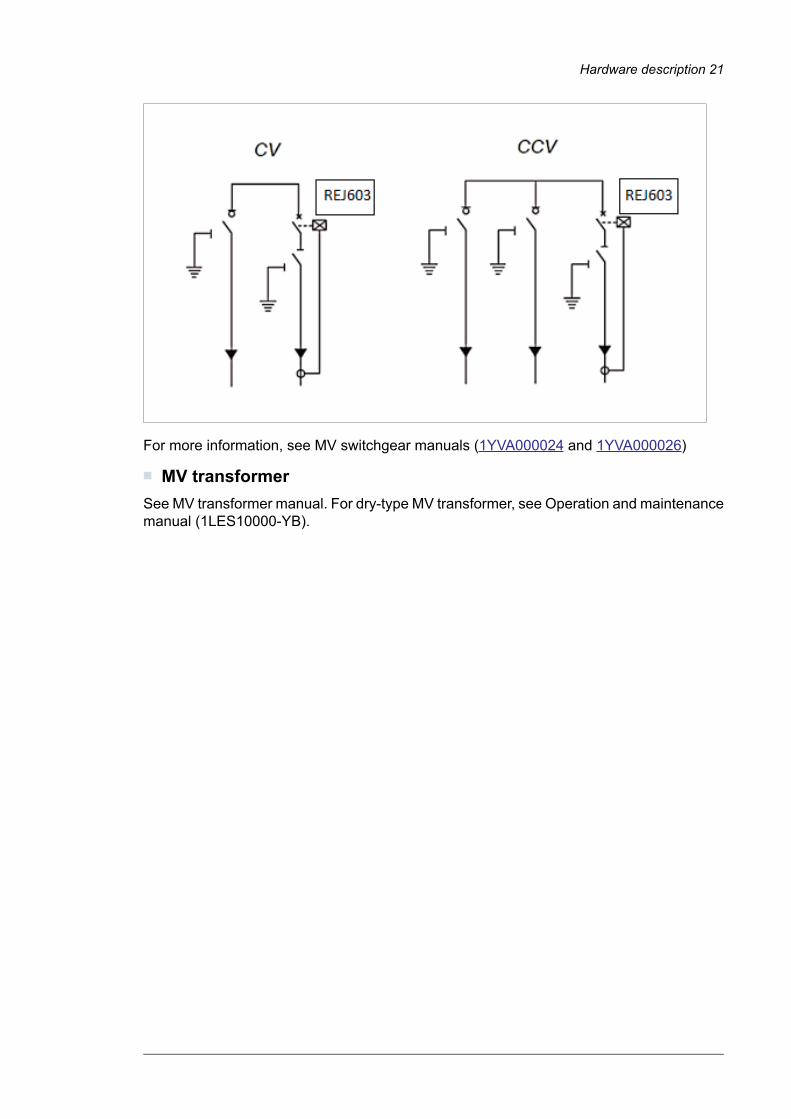
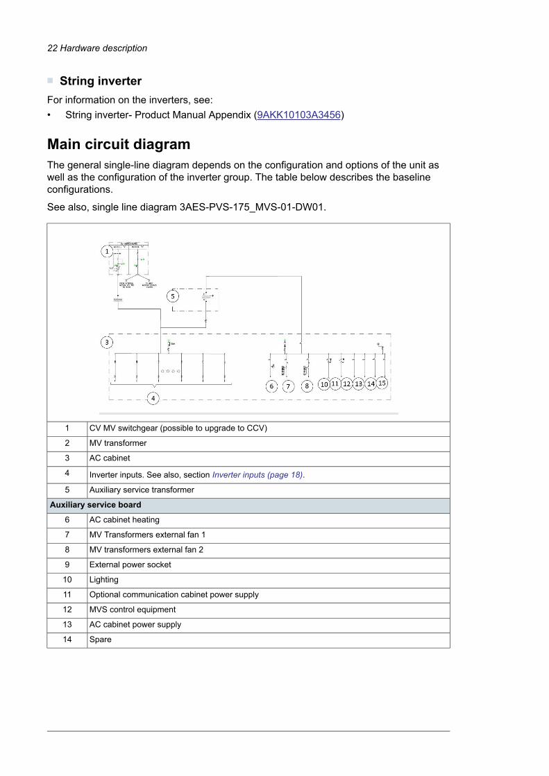
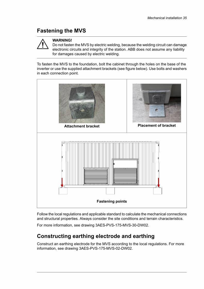

Additional informationTask
Contact your local grid and MVauthority
Make sure that all the local regulations applicable laws andstandard are met
Applicable for C module MVswitchgear
Turn the earthing switch on the grid side of the MV switchgearto the ldquonot earthedrdquo position
Contact your local grid and MVauthority Only authorized personnelare permitted tomake the connections
Ask the power grid owner to connect the station to the powergrid Wait until the station is connected to the power gridbefore proceeding
Applicable for C module MVswitchgear
Turn the disconnecting switch on the grid side of the MVswitchgear to Closed position
Applicable for V module MVswitchgear
Turn the earthing switch on the MV Transformer side of theMV switchgear to the ldquonot earthedrdquo position
Applicable for V module MVSwitchgear
Turn the disconnecting switch on the MV transformer sideof the MV switchgear to the closed position
Applicable for V module MVswitchgear
Close the main breaker of the MV transformer
Make sure that the voltage level on the low voltage side ofthe MV transformer is correct Adjust the MV transformer tapsettings if needed
See MV tansformer documentationRun the MV transformer with no load for several hours
See MV transformer documentationCheck the MV transformer for any malfunctions Observethe temperature listen to audible changes etc
Connecting the AC cabinet
De-energize the MV transformer
Also de-energize (open) all otherswitches disconnectors and breakersof the Auxiliary service board
Close the main switch of the Auxiliary service transformer
Energize the MV transformer
Close the Auxiliary service transformer primary breaker
Must be 230400 V plusmn10Check that the Auxiliary service transformer secondarywinding voltage level is 230400 V
Close the Auxiliary service transformer secondary breaker
Maintain Closed condition for theauxiliary service lines with load Onlyopen switchesbreakers with loads
Close the auxiliary breakers one at a time After closing eachbreaker check the voltage values
Inverters must be de-energizedClose the fuse base switches of the inverter inputs one at atime Check each fuse base for voltage values directly in theinverter input before opening the next fuse base
See inverter manual
See inverter manualFollow the inverter commissioning procedure
If any other optional equipment is integrated into the MVS such as UPS communicationequipment and others then check the equipmentrsquos applicable documentation before executingthe start-up procedure
Start-up and operation 53
12
54
Maintenance
Contents of this chapterThis chapter contains the preventive maintenance instructions for the PVS-175 mediumvoltage station(MVS) The instructions are intended for certified personnel to performmaintenance tasks
WARNINGOnly an authorized electrician is permitted to do maintenance work on the MVSObey the Safety instructions (page 9) and follow the local safety regulations Ifignored physical injury or death or damage to the equipment may occur
WARNINGDo not do electrical work during a thunderstorm
Tools listbull Torx driversbull Philips screwdrivers (PoziDriv)bull Torque wrenchbull Set of wrenches and socketsbull Cable and wire strippersbull Crimping tool and cable lugsbull Voltage detectorbull Personal protective equipment
8Maintenance 55
Tightening torqueUse the torque values given in the table unless otherwise specified
Electrical connections
TorqueBolt and nuts
Brass (Nm)Steel A2-70A4-7088 (Nm)
-09M3
-23M4
-45M5
5080M6
1220M8
2540M10
4070M12
60110M14
90170M16
120240M18
Mechanical connection 1)
TorqueBolt and nuts
A2-70A4-70Quality 88
085121M3
080278M4
16055M5
28095M6
6823M8
1446M10
2479M12
37127M14
56198M16
81283M18
114402M20
1) Not applicable to threaded inserts
56 Maintenance
Threaded inserts
Torque in Nm(steel stainless steel)
Bolt and nuts
79M5
12M6
20M8
34M10
Maintenance intervalsThe maintenance and component replacement intervals are based on the specifiedoperational and environmental conditions
ABB establishes the following as a minimum maintenance schedule The MVS finalmaintenance schedule must be adapted and defined by the maintenance responsible ofthe plant according to the site conditions operations and others
DescriptionAction
Visually inspect and perform maintenance if it is necessaryI
On-siteoff-site performance work (commissioning tests measurements etc)P
Replace the componentR
For more information on maintenance contact your local ABB service representative
Maintenance activitiesPerform the following inspections at least once in every six months
TaskAction
Check the operating environment surroundings and conditionsI
Check the availability of spare partsI
Check for any dust corrosion etc inside and outside the MVSI
Check and clean the inlet and outlet grills amp filtersI
Check the sealing of all cable entries to ensure that the IP protection level is maintainedI
Clean the filters of the air inlet and outletI
Examine the tightness and cleanliness of the main circuit terminals and earth connectionsI
Inspect the general conditions of the MVS (door sealing cooling fan operation etc)I
Inspect the operation of locks hinges and gasketsI
Check that all labels are readable and in proper conditionsI
Examine the condition of the foundationI
Check the maintenance activities of each component in its respective user manual (MVTransformer MV Switchgear AASS Transformer etc)
I
Maintenance 57
TaskAction
Inspect the temperature and operating conditions of the AC Cabinet using thermography I
Examine the grounding system conductivity This must be done in accordance to local regu-lation and standards
I
Maintenance intervals
Years from start-up or intervalComponent
2010
RRCooling fans
R (every six months)Air filters
Obey manufacturer instructionsUPS
Cleaning procedurePerform the following inspections at least once in every six months
WARNINGObey the Safety instructions (page 9) and the local safety regulations If ignoredphysical injury or death or damage to the equipment may occur
WARNINGRead the manuals of other components (inverters UPS etc) The guidelinespecified in this section does not replace the instructions given by the productmanuals of each component
Additional informationTask
Pre-check that there are safe conditions beforestarting any cleaning procedure
Cleaning the MVS
Use pressurized air to clean the externalenclosure floors and gutters
Use pressurized air to clean all air inlets andoutlets including grills
Cleaning the AC Cabinet
If necessary use a duster or pressurized air toclean locations you cannot reach with the vacuumcleaner
Use a vacuum cleaner to clean the floor doorsand interior beams
Remove dust from the air inlets and outlets
Use pressurized air to clean locations withexcessive dust including busbar connections
Cleaning the inverters
Follow the instructions in the inverters manual
Cleaning the MV transformer area
Make sure that the MV and auxiliary transformershave cooled down
58 Maintenance
Additional informationTask
Use a vacuum cleaner to clean the floor doorsand interior beams
See MV transformer manualUse a pressurized air to clean the general dust inthe MV transformer surface and locations withexcessive dust
Use pressurized air to clean locations with excess-ive dust including busbar connections
Clean the surface of the MV transformer with aduster or compressed air
Clean the insulators of the MV transformer
Cleaning the air filters
Clean the air filters by blowing compressed airfrom the inside to the outside through the filteruntil the dust comes off
Loosen and remove the screws on the filter frame
Remove the plastic clips and then remove thegrid
Clean the grill interior with a vacuum cleaner
Install the filter support frames and tighten thescrews
Cleaning the fans
Prevent the circuit breaker from turning on acci-dentally
Turn OFFOPEN the circuit breaker for fan
Measure to make sure that it is not energizedDisconnect the supply and signal cabling
Use compressed air to clean the fans
Cleaning the free area
If necessary use a duster or pressurized air toclean locations you cannot reach with the vacuumcleaner
Use a vacuum cleaner to clean the floor doorsand interior
Cleaning the MV switchgear area
If necessary use a duster or pressurized air toclean locations you cannot reach with the vacuumcleaner
Use a vacuum cleaner to clean the floor doorsand interior metal beams
Maintenance 59
Replacing component1 Loosen and remove the external screws of the ventilation grille
60 Maintenance
2 Pull the top edge and open the ventilation grille
3 Pull the air filter frame from the ventilation grille
4 Remove the plastic clips and the air filter support from the air filter frame5 Check and clean the ventilation grille with a vacuum cleaner6 Clean the air filters with compressed air
WARNINGMake sure that the dust does not enter into the MVS This can cause damageto the equipment
Note If required you can replace the air filter and plastic clips7 Install the air filter into the ventilation grille8 Close the ventilation grille9 Tighten the screws
Maintenance 61
Maintenance of painted surfacesWARNINGObey the Safety instructions (page 9) and the local safety regulations If ignoredphysical injury or death or damage to the equipment may occur
WARNINGObey the Safety instructions (page 9) requirements and specifications of theprimer and paint manufacture
Repainting the scratched areas
Tools and materials
Use the following tools and materials If the listed tools are not available in your local marketyou can use products with similar characteristics approved by a qualified technician andget approval from ABB
MakeSpecificationTool
Silver P80 Triton1 udFlap Disc
Bosch1 udGrinding machine
Ehs10 udFlexible abrasive sponges
-250 mlDegreasing sprays
Finissage Impa1 udBody shop putties
-200 grRags or blower
-10 udDisposable gloves
Uvex Astrospec1 udSafety glasses
-2 udMasks
-2 udBrushes
Maper500 grEpoxy primer
Maper500 grAliphatic polyurethane
Painting the damaged surface (no visible rust)
If there is damage(s) to the paint surface but no damages to the metal surface (ie novisible rust) then follow these instructions1 Clean the damaged area first with a suitable detergent and clean water2 Let the surface dry completely and keep it clean3 Apply the first layer of paint to the damaged area Let it dry thoroughly for at least 12
hours4 Apply the second layer of paint to the damaged area
Painting the damaged surface (visible rust)
If the damage extends to the metal surface or there is visible rust1 Remove the rust with sandpaperpolishing disk
62 Maintenance
2 Clean the damaged area and its surroundings using a cloth or blower3 If necessary apply putty to even out the surface4 Coat the damaged area with an epoxy primer Let it dry thoroughly (for at least 24 hours)5 Apply first layer of paint to the damaged area Let it dry thoroughly (for at least 12 hours)6 Apply second layer of paint to the damaged area7 Apply final layer (eg Aliphatic Polyurethane coating)
Maintenance of Zinc coated surfacesPay attention to doors and lower parts of the walls These areas have potentially corrosiveelements such as dust and humidity
If there is damage to the zinc-coating1 Carefully remove any rust with sandpaper2 Clean the damaged area and its surroundings3 Coat the damaged area with the zinc coating Use Wuumlrth Zinc 300 for a thicker coat
On large areas you can use Wuumlrth Zinc Spray Perfect to ease the work and to get aneven surface
Maintenance of grounding bars and points Toolsbull Steel woolbull Ensto SR1 joint compound or equivalentbull 42839 Wuumlrth protective wax or equivalent
Procedure1 Examine the condition of the grounding bar and grounding cables in the MV switchgear
area If there is any visible corrosion remove the cables and remove the corrosion withsteel wool Apply joint compound between the grounding bar and the joint surfaces ofthe cable terminal
2 Change the spring lock washers Tighten the cables to the nominal torque values3 If corrosion is more apply protective wax spray on the grounding bar and the cable
terminals
Maintaining external hinges and locks Toolsbull Cleaning materialsbull Hinge lubricant Wuumlrth HHS20000 0893 106 or equivalentbull Lock lubricant Wuumlrth maintenance spray 0893 051 or equivalent
Procedure1 Tomaintain the external hinges and locks use the recommended lubricants and lubricate
the locks and hinges
WARNING Do not use lubricants with silicone
Maintenance 63
2 After lubricating clean the excess lubricant
Replacing the door limit switchWARNINGMake sure that the circuit breaker is open and cannot be closed accidently whenperforming the task
1 Open the main circuit breaker of the auxiliary panel2 Check and make sure that no voltage is connected to the limit switch door and the light
lane3 Loosen the limit switch screws4 Replace the limit switch and verify the connections and operation For more information
refer to the sensor manual5 Close the circuit breaker and make sure that the door limit switch operates as expected
64 Maintenance
Technical data
Contents of this chapterThis chapter contains the technical data of the PVS-175 medium voltage station (MVS)
9Technical data 65
Technical data and types PVS-175 MVSType code (PVS-175-TL-
Data66606290592055505180481044404070370033302960259022201850
3634323028262422201816141210Number of in-verters inparallel
66606290592055505180481044404070370033302960259022201850Maximum ratingin kVA
LV distribution panel
3634323028262422201816141210Number of fuseprotectedfeeders
200 AFuse rating offeeders
YesBreakable onload
Type 2 (type 1 + 2 optional)Over voltageprotection -replaceablesurge arrester
MV transformer
Vacuum cast coil dry type (AF)Transformertype
66606290592055505180481044404070370033302960259022201850AC power at30degC in kVA
63005950560052504900455042003850350031502800245021001750AC power at40degC in kVA
800 VLow voltagelevel
le 36 kVMedium voltagelevel range
50 Hz or 60 HzRatedfrequency
plusmn 2 x 25Tap changer
AI AIWindingmateri-al (primary secondary)
YesEco efficiencyoptional
MV switchgear
ABB SafePlus (SF6-insulated)Switchgear type
630 ARated current
Single (CV) or double feeder (CCV)Configuration
Circuit breaker (16 kA or 20 kA 20 kA or 25 kA)Protection (upto 24 kV up to36 kV)
ABB REJ603 (others on request)Protection relaytype
YesMotorizedoptional
66 Technical data
Type code (PVS-175-TL-Data
66606290592055505180481044404070370033302960259022201850
Auxiliary supply
10 kVA (higher on request)Auxiliarytransformerpower
800 400-230 VAuxiliarytransformervoltage
YesLow voltagedistribution pan-elfor auxiliaryfunctions
Mechanical characteristics
5700 x 2150 x 2500 mmLength WidthHeight(L times W times H)
15141413131212111110101099Weight approxton
Environmental
-25 C hellip +60degC (with derating above 40degC)Operatingtemperaturerange
le 2000 mOperatingaltitude range
le 95Relativehumidity(non-condens-ing)
IP 54Environmentalprotection rat-ing
C4 (C5M optimal)Paintingcorrosionprotection
Product compliance
IEC 60364 IEC 61936-1 IEC 60502-1Conformity
Technical data 67
68
Drawings
Contents of this chapterThis chapter contains the technical drawings of PVS-175 medium voltage station (MVS)
List of technical drawingsThe list includes two types of drawingsbull Product SeriesmdashStandard product series drawings that can be consulted prior to the
purchase of the unitbull Project SpecificmdashDrawings specific to a project that are delivered with the unit only on
request
TypeDescriptionDrawing code
Product SeriesSingle Line Diagram3AES-PVS-175-MVS-01-DW01
Product SeriesGrounding Layout3AES-PVS-175-MVS-02-DW02
Product SeriesDimensional Layout3AES-PVS-175-MVS-30-DW01
Product SeriesFootprint3AES-PVS-175-MVS-30-DW02
Project SpecificAuxiliary Cabinet3AES-PVS-175-MVS-14-DW03
Project Specific (if applicable)Communication Cabinet3AES-PVS-175-MVS-15-SL01
Project Specific (if applicable)UPS Connection3AES-PVS-175-MVS-16-SP01
10Drawings 69
mdashFurther information
Product and service inquiriesAddress any inquiries about the product to your local ABB representative quoting the type designation and serial number of the unit in question A listing of ABB sales support and service contacts can be found by navigating to newabbcompower-converters-inverterssolar
Product trainingFor information on ABB product training navigate to newabbcomservicetraining
Providing feedback on ABB Drives manualsYour comments on our manuals are welcome Navigate to newabbcompower-converters-invertersdocument-library
Document library on the InternetYou can find manuals and other product documents in PDF format on the Internet at newabbcompower-converters-invertersdocument-library
wwwabbcomsolarinverters
3AES-PVS-175-MVS-00-MA01-AA
copy 2019 ABB Spain All Rights ReservedSpecifications subject to change without notice 3AES-PVS
-175-M
VS-00-M
A01-ARev
A(EN)E
FFECTIVE2019-05-14
- Table of contents
- Safety instructions
-
- Contents of this chapter
- Use of warnings
- Allowed usage
- Safe installation start-up and maintenance
-
- General safety instructions
- MVS working area safety
-
- Personal protective equipment (PPE)
- Safety instructions for MV switchgear and MV transformer area
- Safety instructions for the auxiliary services board
-
- Safe operation
-
- Hardware description
-
- Contents of this chapter
- Product overview
- External dimensions
- Layout drawing
- Working areas and main components
-
- Main components
- AC cabinet components
- Inverter inputs
- Auxiliary service board
- MV switchgear
-
- MV switchgear circuit
-
- MV transformer
- String inverter
-
- Main circuit diagram
- Type designation label
- Type designation key
-
- MVS optional codes
-
- Storing lifting and transporting
-
- Contents of this chapter
- Storing
-
- Conditions for using desiccant bags
-
- Lifting
-
- Tools used for lifting
- Lifting instructions
-
- Transporting
-
- Incoming inspection at arrival
-
- Mechanical installation
-
- Contents of this chapter
- Safety
- Tools
- Foundation guidelines
- Placing the MVS on the foundation
- Fastening the MVS
- Constructing earthing electrode and earthing
- Filling the pit and finalizing the surroundings
- Adding weather protection hoods
-
- Tools
- Procedure
-
- Electrical installation
-
- Contents of this chapter
- Routing the cables
- Earthing
- Protective earthing (grounding) inside the MVS
- Measuring the insulation resistance of the cabling
- Connecting the inverter inputs
- Connecting the communication and auxiliary cabling (Optional)
- Connecting the power grid cabling to the MV switchgear
-
- Finalizing the installation
-
- Contents of this chapter
- Finalizing the installation
- Landscaping the station
- Checking the installation of MVS
-
- Start-up and operation
-
- Contents of this chapter
- Tools needed
- Prerequisite
- Start-up procedure
-
- Maintenance
-
- Contents of this chapter
- Tools list
- Tightening torque
- Maintenance intervals
-
- Maintenance activities
- Maintenance intervals
-
- Cleaning procedure
- Replacing component
- Maintenance of painted surfaces
-
- Repainting the scratched areas
-
- Tools and materials
- Painting the damaged surface (no visible rust)
- Painting the damaged surface (visible rust)
-
- Maintenance of Zinc coated surfaces
-
- Maintenance of grounding bars and points
-
- Tools
- Procedure
-
- Maintaining external hinges and locks
-
- Tools
- Procedure
-
- Replacing the door limit switch
-
- Technical data
-
- Contents of this chapter
- Technical data and types PVS-175 MVS
-
- Drawings
-
- Contents of this chapter
- List of technical drawings
-
- Further information
-
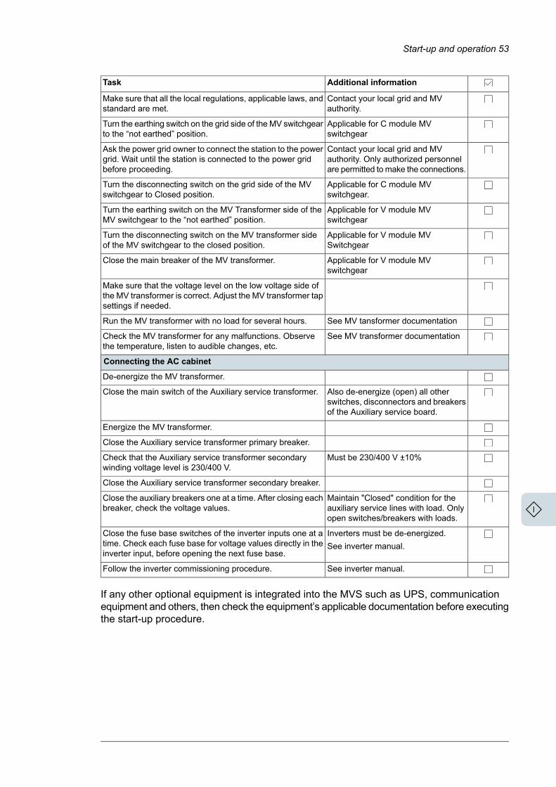
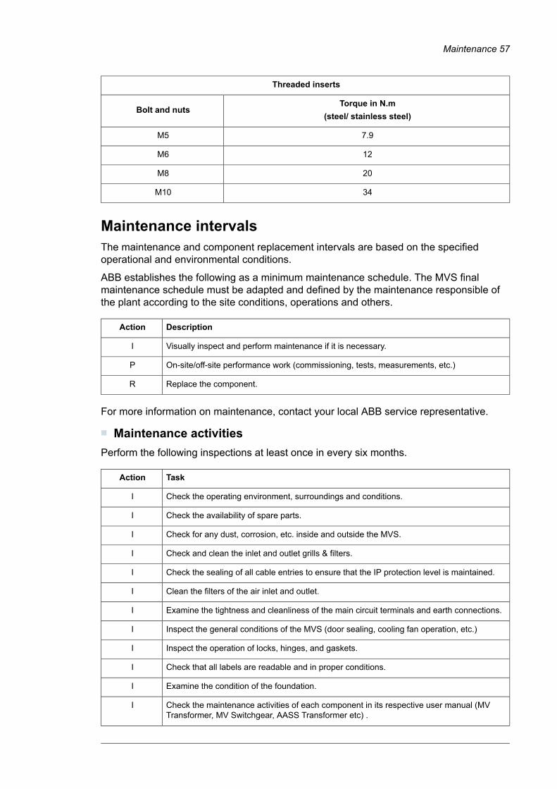
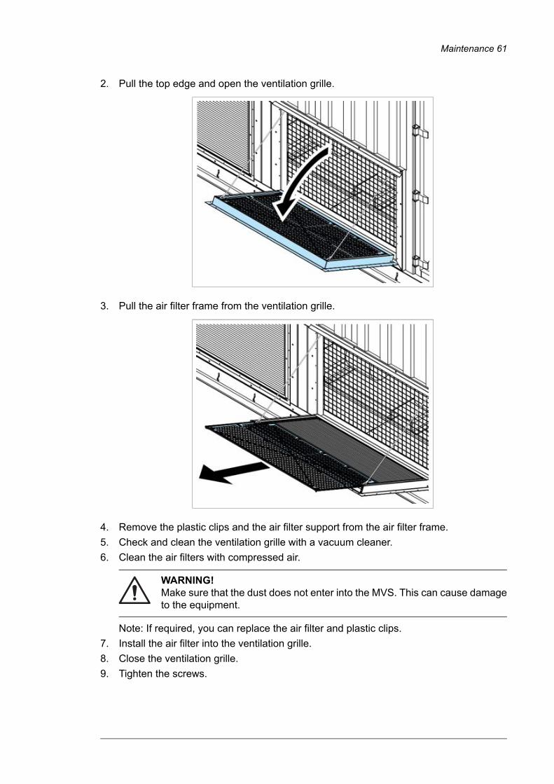
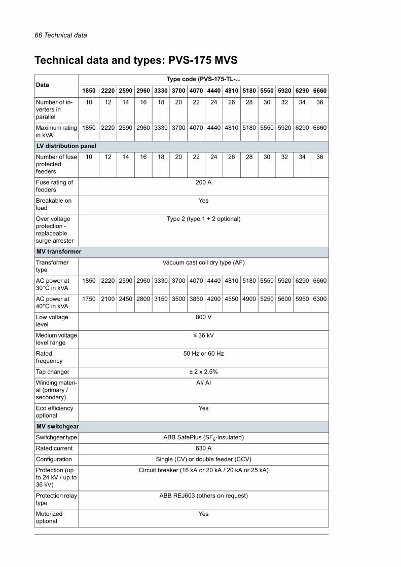