abb’s ls series mechanical level switches abb · abb’s ls series mechanical level switches are...
TRANSCRIPT


ABB’s LS Series Mechanical Level Switches are the most rugged and durable liquid point-level detection products in the industrial marketplace today. ABB innovations such as the one-step switch point adjust and the hermetically sealed/dual compartment switching mechanism have eliminated the need for bulky housing covers that are associated with cracking, moisture ingress, high temperature fatigue, and ultimately switch failure. This configuration guide contains general guidelines and ordering data that will assist you in selecting the best float or displacer operated switch for your specific fluid level application. These switches are available in flanged or sealed chambers or as insertion models. ABB has over 100 configurations available.
LS Series

General
Over 10,000 global installations in applications ranging from condensate to CO2 to crude oil
Easily retrofitted to most competitor models
Designed to handle specific gravities as low as 0.25, temperatures as high as 1000° F (538°
C), and pressures up to 4500 psi (310 bar)
Choose from eight (8) standard designs and six (6) different switching mechanisms
Worldwide delivery
Five year manufacturer warranty
Quality Certifications ABB is the only level gauge manufacturer in North America to hold the following certifications:
ASME (U, S, and UM Stamps), PED, and National Boiler Certification
Sensing Elements
Each float and displacer is precision fabricated to indicate true fluid level.
Choices for float and displacer materials include: 316 Stainless Steel, Hastelloy C-276, and
Titanium (Grades 2 and 5). Ceramic is also available for displacers.
Switching Mechanisms
All stainless steel housing construction with NEMA 4X ratings
Temperature ratings available from -320°F (-190°C) to 1000°F (538°C)
Choices for switching mechanism types include: Reed, Cam Action, and Pneumatic
Available switching mechanisms are hermetically sealed, standard open contacts, or
pneumatic contacts
Agency Listings for most switches include: FM, CSA, and ATEX
Chambers
Choices for chamber material include: Carbon Steel, 316 Stainless Steel, Duplex Stainless
Steel, Hastelloy C-276, Hastelloy B-3, and P11 and P91 Chrome Molly Steel.
Flanged models have standard slip-on ―top access connection‖ flanges. Weld-neck flanges are
optional.
Designed to guidelines of ASME B31.1 and B31.3
All welders and fabrication procedures are qualified and maintained per ASME
Certification to NACE MRO175 and MRO103 is available
Process Connections
A wide variety of process connection types include: Flanges (slip-on, weld-neck), Socket Weld,
and Threaded (NPT)
Available flange ratings and sizes include: ASME, DIN, HG, and most International and cus-
tomer specified flange types
Options
Custom Calibration and Switch Point
High Temperature and Cryogenic Insulation
Steam Tube and Electrical Heat Tracing
Vent, Drain, and Process Isolation Valves
Stilling Wells and Support Tubes for Turbulent Conditions
Features & Options LS Series
OIL AND GAS
Separator levels
PETROCHEMICAL
Catalytic Cracker
Distillation
Fractionation
Hydrotreater/Reformer
Coker
Flare Knockout Tank
POWER
Fuel Storage
Steam Turbine Drip Legs
Hotwell Condenser
Feed Water Heaters
Demineralization Tanks
Ash Precipitator/Scrubber
Steam Drum Level
Lube Oil Systems
CHEMICAL & OTHER
Storage & Batch Tank Level
High Level Alarm Safety Shutdown
Water/Wastewater Treatment Tanks
Pulp Processing Tanks
Lube Oil Tanks
Sump Control
A P P L I C A T I O N S
Applications & Basics LS Series
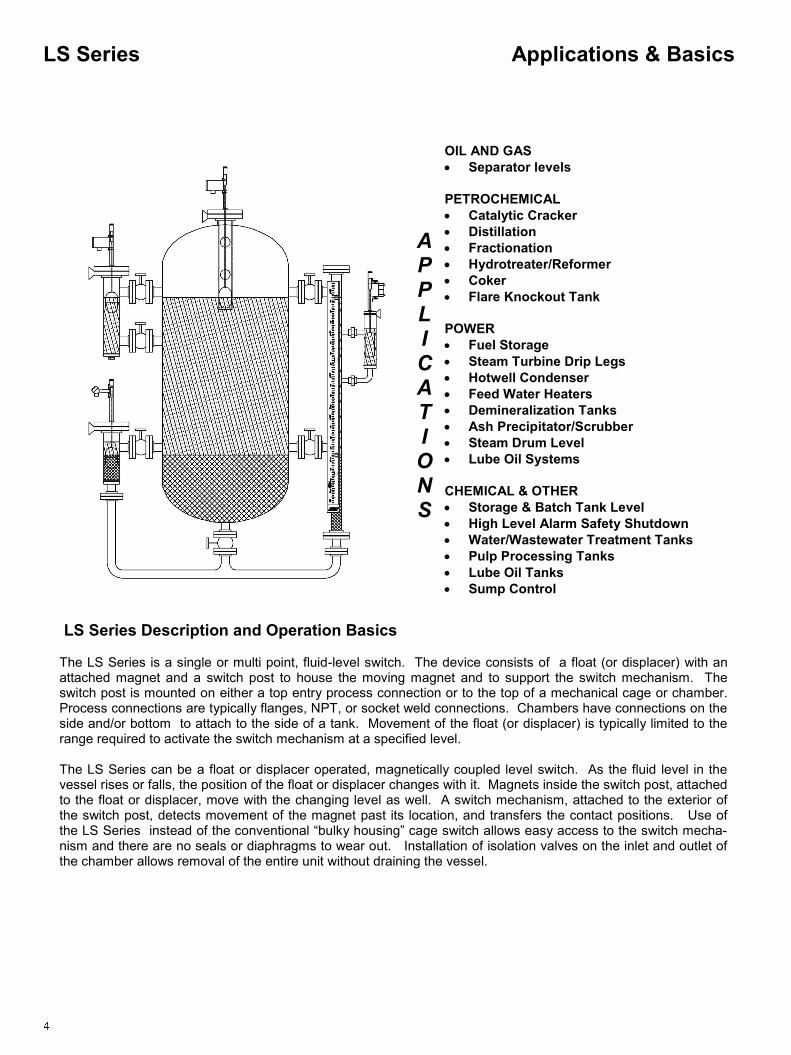
LS Series Description and Operation Basics
The LS Series is a single or multi point, fluid-level switch. The device consists of a float (or displacer) with an attached magnet and a switch post to house the moving magnet and to support the switch mechanism. The switch post is mounted on either a top entry process connection or to the top of a mechanical cage or chamber. Process connections are typically flanges, NPT, or socket weld connections. Chambers have connections on the side and/or bottom to attach to the side of a tank. Movement of the float (or displacer) is typically limited to the range required to activate the switch mechanism at a specified level. The LS Series can be a float or displacer operated, magnetically coupled level switch. As the fluid level in the vessel rises or falls, the position of the float or displacer changes with it. Magnets inside the switch post, attached to the float or displacer, move with the changing level as well. A switch mechanism, attached to the exterior of the switch post, detects movement of the magnet past its location, and transfers the contact positions. Use of the LS Series instead of the conventional ―bulky housing‖ cage switch allows easy access to the switch mecha-nism and there are no seals or diaphragms to wear out. Installation of isolation valves on the inlet and outlet of the chamber allows removal of the entire unit without draining the vessel.

Quality Manufacturing Switch Mechanism Comparison 6 Chamber Comparison 7 Fundamentals Float Switches 8 Displacer Switches 8 How to Order 9 Float Switches 500/510 Series - Top Mount Float 10 600 Series - Flanged Chamber Float 15 700 Series - Sealed Chamber Float 27 Displacer Switches 550/560 Series - Top Mount Displacer 11 800 Series - Flanged Chamber Displacer 21 900 Series - Sealed Chamber Displacer 33 Switching Mechanisms and Housings Switches 39 Accessories High Temperature & Cryogenic Isolation Insulation 41 Vent, Drain & Process Isolation Valves 42 Stilling Wells & Support Tubes 43 Appendix Pipe Pressure Ratings (Table 1) 44 Flange Pressure Ratings (Table 2) 46 Process Connection Configuration (Tables 3 & 4) 47 Conversions (Table 5) 51
Section
Table of Contents Mechanical Level Switches
Page

Switching Mechanism Comparison
The ABB standard switching mechanism is a magnetically actuated double pole double throw (DPDT)switch. ABB offers a variety of magnetically actuated switch mechanisms (reed, cam-action and pneumatic style) with SPDT, DPDT, or pneumatic outputs. When a ABB switch mechanism (single or multiple) is mounted on a LS Series mechanical switch, it can sense a high or low level within a vessel. The unique magnetic coupling action eliminates the need for seals, diaphragm springs, or torque tubes because there is no physical contact with the process. The switch configuration also has no process connections which ensures complete isolation from the process. The 360° adjustable switch mechanism does not require the removal of the conventional bulky cover and can be easily positioned at the desired switch point. The compact, maintenance free design, requires no periodic cleaning or operational checks and contains hermetically sealed contacts that ensure high reliability and extended product life.
Quality Manufacturing Switch Mechanism Comparison
ABB Standard with MS41 Switching Mechanism
Competitor Standard
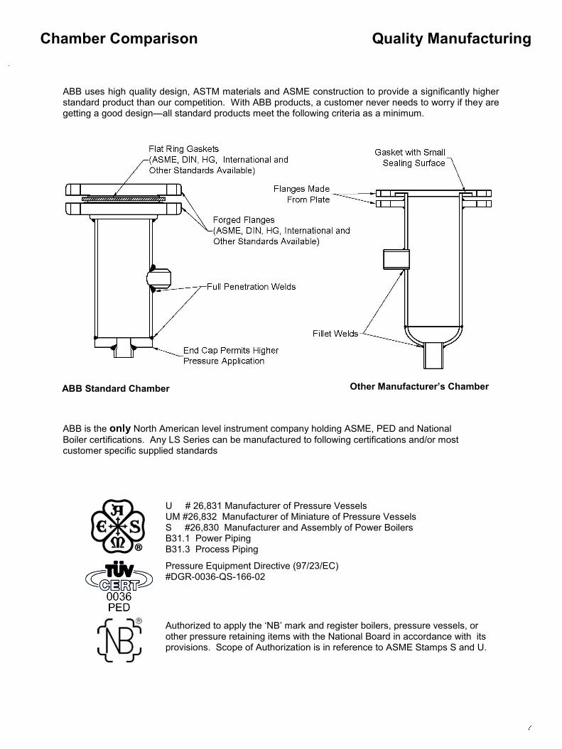
Quality Manufacturing Chamber Comparison
ABB uses high quality design, ASTM materials and ASME construction to provide a significantly higher standard product than our competition. With ABB products, a customer never needs to worry if they are getting a good design—all standard products meet the following criteria as a minimum.
ABB is the only North American level instrument company holding ASME, PED and National
Boiler certifications. Any LS Series can be manufactured to following certifications and/or most customer specific supplied standards
ABB Standard Chamber Other Manufacturer’s Chamber
U # 26,831 Manufacturer of Pressure Vessels UM #26,832 Manufacturer of Miniature of Pressure Vessels S #26,830 Manufacturer and Assembly of Power Boilers B31.1 Power Piping B31.3 Process Piping
Pressure Equipment Directive (97/23/EC) #DGR-0036-QS-166-02
Authorized to apply the ‗NB‘ mark and register boilers, pressure vessels, or other pressure retaining items with the National Board in accordance with its provisions. Scope of Authorization is in reference to ASME Stamps S and U.

Float Operated Level Switches Model Series 500, 510, 600, 700
The float rides on the process fluid and tracks with the liquid level movement. As the fluid level in the vessel (or external cage) rises or falls, the position of the float changes. Magnets attached to a float guide rod (located inside the sensing tube) also move with the changing level. A switch mechanism (electrical or pneumatic) attached to the exterior of the sensing tube is actuated by a rising level and de-actuated by a falling level. Floats can utilize multiple switching mechanisms. Consult the factory for special float switching arrangements.
Fundamentals Float & Displacer Switches
Displacer Operated Level Switches Model Series 550, 560, 800, 900
Displacer switches offer an alternative means of fluid level measurement different from the traditional float device. While a float follows the liquid level, a displacer remains partially or completely submerged. The buoyancy of the displacer is increased as it becomes covered by more liquid. Therefore, when the displacer weight drops below the spring tension (rising level), the switch mechanism is actuated. Hence, when the displacer weight increases to that greater than the spring tension (falling level), the switch mechanism is de-actuated. Displacer switches can be utilized in some high pressure and low specific gravity applications where float designs are cost prohibitive or impossible to implement.
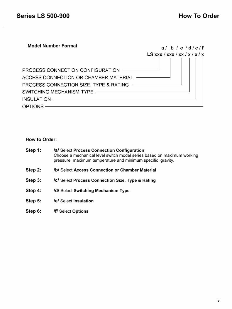
How to Order: Step 1: /a/ Select Process Connection Configuration Choose a mechanical level switch model series based on maximum working pressure, maximum temperature and minimum specific gravity.
Step 2: /b/ Select Access Connection or Chamber Material
Step 3: /c/ Select Process Connection Size, Type & Rating
Step 4: /d/ Select Switching Mechanism Type
Step 5: /e/ Select Insulation
Step 6: /f/ Select Options
How To Order Series LS 500-900
Model Number Format

Top Mount Float Series
Step 1:
/a/ Select PROCESS CONNECTION CONFIGURATION
Consult ABB factory for other materials and process conditions not listed.
Model Number Selection: Step 1 Series LS 500/510
Float Materials: 316 SS (S6) is the standard. The following materials and others are available. Hastelloy C276; Titanium Gr2 and Titanium Gr5. Construction materials are determined by application specifics (i.e. temperature, pressure and specific gravity).
Pressure at Indicated Temperature
Model Series
37.7° C (bar)
450° F (psig)
232° C (bar)
Float Mat'l Code
Minimum S.G.
100° F (psig)
5x1 225 15.5 207 14.3 T2 .4
5x2 500 34.5 460 31.7 S6 .68
5x3 750 51.7 690 47.6 S6 .52
Series LS 5xx - Top Mounted Float
50x - Flanged Process Connection Example Application Data: Pressure 26bar, Temperature 225°C, S.G. .68, 2 4‖ Flanged Process Connection, 32 3/8‖ Pneumatic Switch Point Location
Example: LS502/CST/SR43/F/IP/SP=32 3/8in.
Model (Series) (a)
Access Connection
Material (b)
Access Connection Size,
Type & Rating (c)
Switching Mechanism
Type (d)
Insulation (e)
Options (f)
502 CST SR43 F IP SP=32 3/8”
Model Number Formats
51x NPT 50x Flanged
Note: For both the 50x and 51x, use the table below to select model series.
Top Mount Float Series

Model Number Selection: Step 1 Series LS 550/560
Model Number Formats
Step 1:
/a/ Select PROCESS CONNECTION CONFIGURATION
56x NPT 55x Flanged
Pressure at Indicated Temperature
Model Series
100° F (psig)
37.7° C (bar)
450° F (psig)
232° C (bar)
Displacer Mat'l
Minimum S.G.
5x1 1000 68.9 750 51.7 S6 .6
5x2 275 19.0 182 12.5 S6 .6
Consult ABB factory for other materials and process con-ditions not listed.
Top Mount Displacer Series
Top Mount Displacer Series
Series LS 5xx - Top Mounted Displacer
56x - Threaded Process Connection Example Application Data: Pressure: 17 bar, Temperature: 35°C, S.G.: 0.76,
1.5‖ 1.5‖ NPT Process Connection, Switch Point Location 20 3/4‖
Example: LS562/SS6/P15/E/X/SP=20 3/4in.
Model (Series) (a)
Access Connection
Material (b)
Access Connection Size,
Type & Rating (c)
Switching Mechanism
Type (d)
Insulation (e)
Options (f)
562 SS6 P15 E X SP=20 3/4”
Displacer Materials: 316 SS (S6) is the standard. The following materials and others are available. Hastelloy C276; Titanium Gr2, Titanium Gr5 and Porcelain. Construction materials are determined by application specifics (i.e. temperature, pressure and specific gravity).
Note: For both the 55x and 56x, use the table below to select model series.
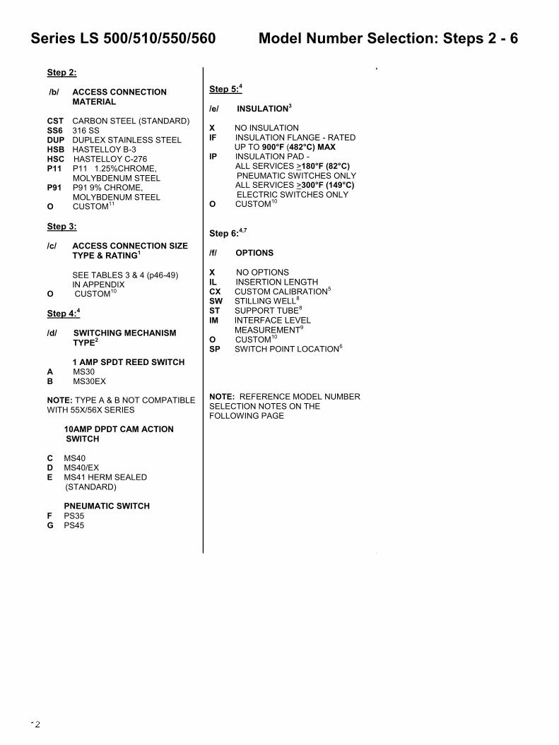
Step 5:4 /e/ INSULATION3 X NO INSULATION IF INSULATION FLANGE - RATED UP TO 900°F (482°C) MAX IP INSULATION PAD - ALL SERVICES >180°F (82°C)
PNEUMATIC SWITCHES ONLY ALL SERVICES >300°F (149°C)
ELECTRIC SWITCHES ONLY O CUSTOM10
Step 6:4,7 /f/ OPTIONS X NO OPTIONS IL INSERTION LENGTH CX CUSTOM CALIBRATION5 SW STILLING WELL8
ST SUPPORT TUBE8
IM INTERFACE LEVEL MEASUREMENT9
O CUSTOM10 SP SWITCH POINT LOCATION6
NOTE: REFERENCE MODEL NUMBER
SELECTION NOTES ON THE FOLLOWING PAGE
Step 2: /b/ ACCESS CONNECTION MATERIAL CST CARBON STEEL (STANDARD) SS6 316 SS DUP DUPLEX STAINLESS STEEL HSB HASTELLOY B-3 HSC HASTELLOY C-276 P11 P11 1.25%CHROME,
MOLYBDENUM STEEL P91 P91 9% CHROME,
MOLYBDENUM STEEL O CUSTOM11
Step 3: /c/ ACCESS CONNECTION SIZE
TYPE & RATING1
SEE TABLES 3 & 4 (p46-49) IN APPENDIX O CUSTOM10
Step 4:4
/d/ SWITCHING MECHANISM TYPE2 1 AMP SPDT REED SWITCH A MS30 B MS30EX
NOTE: TYPE A & B NOT COMPATIBLE
WITH 55X/56X SERIES 10AMP DPDT CAM ACTION SWITCH C MS40 D MS40/EX E MS41 HERM SEALED
(STANDARD) PNEUMATIC SWITCH F PS35 G PS45
Model Number Selection: Steps 2 - 6 Series LS 500/510/550/560
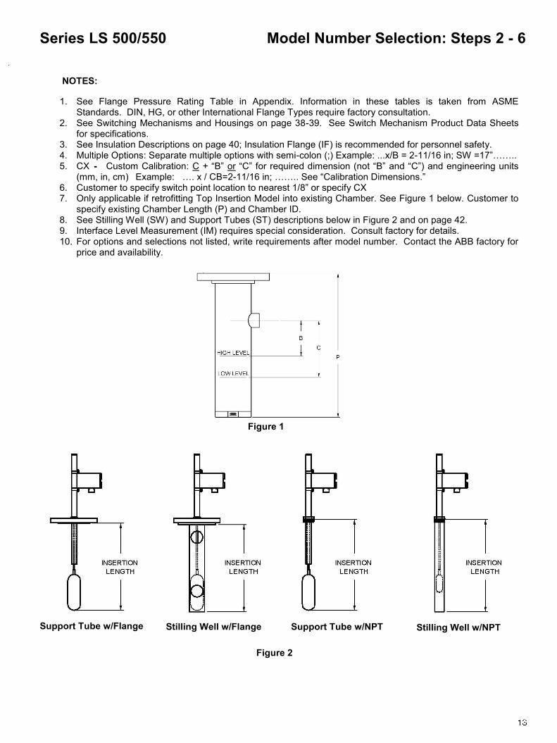
NOTES:
1. See Flange Pressure Rating Table in Appendix. Information in these tables is taken from ASME Standards. DIN, HG, or other International Flange Types require factory consultation.
2. See Switching Mechanisms and Housings on page 38-39. See Switch Mechanism Product Data Sheets for specifications.
3. See Insulation Descriptions on page 40; Insulation Flange (IF) is recommended for personnel safety. 4. Multiple Options: Separate multiple options with semi-colon (;) Example: ...x/B = 2-11/16 in; SW =17‖…….. 5. CX - Custom Calibration: C + ―B‖ or ―C‖ for required dimension (not ―B‖ and ―C‖) and engineering units
(mm, in, cm) Example: …. x / CB=2-11/16 in; …….. See ―Calibration Dimensions.‖ 6. Customer to specify switch point location to nearest 1/8‖ or specify CX 7. Only applicable if retrofitting Top Insertion Model into existing Chamber. See Figure 1 below. Customer to
specify existing Chamber Length (P) and Chamber ID. 8. See Stilling Well (SW) and Support Tubes (ST) descriptions below in Figure 2 and on page 42. 9. Interface Level Measurement (IM) requires special consideration. Consult factory for details. 10. For options and selections not listed, write requirements after model number. Contact the ABB factory for
price and availability.
Model Number Selection: Steps 2 - 6 Series LS 500/550
Stilling Well w/Flange Stilling Well w/NPT
Figure 1
Figure 2
Support Tube w/Flange Support Tube w/NPT

Calibration Dimensions for LS 500/510/550/560 Series
Dimensions in this catalog are for reference only. They may be changed without notice. Contact the factory for certified drawings for a particular model number. Note: It is important to consider the installation configuration when selecting the process connection. Be sure that the float will fit through the process connection, or that the vessel has access to attach the float from inside the vessel after instrument installation.
Dimensions Series LS 500/510/550/560
500/510 Series (Float)
Model Float Size Minimum Insertion Maximum Insertion Minimum
Opening Size in mm in mm
5x1 TBD 4-1/4 108 48 1219 TBD
5x2 TBD 4-1/2 114 48 1219 TBD
5x3 TBD 4-1/4 108 48 1219 TBD
550/560 Series (Displacer)
Model Displacer
Size
Maximum Insertion Length
in mm
5x1 TBD 48 1219
5x2 TBD 48 1219
50x Flanged 51x NPT
55x Flanged 56x Flanged
Note: For longer Insertion Length, consult ABB factory.
Note: For longer Insertion Length, consult ABB factory.

A – Side/Side
Carbon Steel Chamber (A106 GrB)
Stainless Steel Chamber (316SS)
Step 1:
/a/ Select PROCESS CONNECTION CONFIGURATION
62x Side/Side/Drain 63x Side/Bottom 61x Side/Side
Consult ABB factory for other chamber materials and process conditions not listed.
Model Number Selection: Step 1 Series LS 600
Pressure at Indicated Temperature
Model Series
37.7° C (bar)
450° F (psig)
232° C (bar)
750° F (psig)
399° C (bar)
Float Mat'l Code
Minimum S.G.
100° F (psig)
1000°F (psig)
538°C (bar)
6x1 285 19.7 185 12.8 95 6.6 TBD 0.44 23 1.6
6x2 500 34.5 460 31.7 389 26.8 TBD 0.60 354 24.3
6x3 740 51.0 622 42.9 505 34.8 TBD 0.44 418 28.8
6x4 990 68.2 822 56.6 778 53.6 TBD 0.61 676 46.6
6x5 285 19.7 185 12.8 95 6.6 TBD 0.38 23 1.6
6x6 285 19.7 185 12.8 95 6.6 TBD 0.64 23 1.6
6x7 350 24.1 322 22.2 272 18.8 TBD 0.60 247 17.1
6x8 740 51.0 622 42.9 389 26.8 TBD 0.65 281 19.3
6x9 1250 86.2 1150 79.3 TBD TBD TBD 0.77 TBD TBD
Pressure at Indicated Temperature
Model Series
100° F (psig)
37.7° C (bar)
450° F (psig)
232° C (bar)
750° F (psig)
1000°F (psig)
Minimum S.G.
399° C (bar)
538°C (bar)
Float Mat'l Code
6x1 275 19.0 182 12.5 95 6.6 27 0.44 1.8 TBD
6x2 500 34.5 460 31.7 389 26.8 354 0.60 24.6 TBD
6x3 720 49.6 497 34.3 425 29.3 287 0.44 19.4 TBD
6x4 1000 68.9 920 63.4 778 53.6 708 0.61 48.9 TBD
6x5 275 19.0 182 12.5 95 6.6 27 0.38 1.8 TBD
6x6 275 19.0 182 12.5 95 6.6 27 0.64 1.8 TBD
6x7 350 24.1 322 22.2 272 18.8 247 0.60 16.9 TBD
6x8 720 49.6 497 34.3 425 29.3 287 0.65 19.6 TBD
6x9 1250 86.2 992 68.4 TBD TBD TBD 0.77 TBD TBD
Model Number Formats
Flanged Chamber Float Series
Series LS 6xx - Flanged Chamber Float
61x - Side/Side Process Connections Example Application Data: Pressure 52bar, Temperature 230°C, S.G. .68, 0.61, 2‖ Flange Process Connection, Pneumatic Output , 3/4‖ Vent Valve
Example: LS614/CST/N3F0W9/N74-WR26/F/IH2;IF/VV; C=300mm
Model (Series) (a)
Chamber Material
(b)
Process Connection Size,
Type & Rating (c)
Switching Mechanism
Type (d)
Insulation (e)
Options (f)
614 CST N3F0W9/N74-WR26 F IH2;IF VV; C=300mm
Float materials: 316 SS (S6) is the standard. The following materials and others are available. Hastelloy C276; Titanium Gr2 and Titanium Gr5. Construction materials are determined by appli-cation specifics (i.e. tem-perature, pressure and specific gravity).

Step 5:4 /e/ INSULATION3 X NO INSULATION IP INSULATION PAD - ALL SERVICES >180°F (82°C)
PNEUMATIC SWITCHES ONLY ALL SERVICES >300°F (149°C)
ELECTRIC SWITCHES ONLY IH1 HIGH TEMP. INSULATION;
FLOAT CHAMBER ONLY; 1/2‖THICK, 250°F (121°C) MAX IH1D HIGH TEMP. INSULATION;
FLOAT CHAMBER & VENT/ DRAIN FLANGES; 1/2‖THICK, 250°F (121°C) MAX IH2 HIGH TEMP. INSULATION;
FLOAT CHAMBER ONLY; 1‖THICK, 500°F (260°C) MAX IH2D HIGH TEMP. INSULATION;
FLOAT CHAMBER & VENT/ DRAIN FLANGES; 1‖THICK, 500°F (260°C) MAX IH3 HIGH TEMP. INSULATION;
FLOAT CHAMBER ONLY; 2‖THICK, 900°F (482°C) MAX IH3D HIGH TEMP. INSULATION;
FLOAT CHAMBER & VENT/ DRAIN FLANGES; 2‖THICK, 900°F (482°C) MAX
IF INSULATION FLANGE - RATED UP TO 900°F (482°C) MAX IL1 CRYOGENIC INSULATION;
2‖THICK; SINGLE LAYER; -100°F (-73°C) MINIMUM IL2 CRYOGENIC INSULATION;
3‖ THICK; DOUBLE LAYER; -200°F (-129°C) MINIMUM IL3 CRYOGENIC INSULATION;
4‖ THICK; DOUBLE LAYER; -320°F (-196°C) MINIMUM O CUSTOM12
Step 2: /b/ CHAMBER MATERIAL CST CARBON STEEL (STANDARD) SS6 316 SS DUP DUPLEX STAINLESS STEEL HSB HASTELLOY B-3 HSC HASTELLOY C-276 P11 P11 1.25%CHROME,
MOLYBDENUM STEEL P91 P91 9% CHROME,
MOLYBDENUM STEEL O CUSTOM11
Step 3: /c/ PROCESS CONNECTION SIZE
TYPE & RATING1,9, 10
SEE TABLES 3 & 4 (p46-49) IN APPENDIX O CUSTOM12
Step 4:4
/d/ SWITCHING MECHANISM TYPE2 1 AMP SPDT REED SWITCH A MS30 B MS30EX
10AMP DPDT CAM ACTION SWITCH C MS40 D MS40/EX E MS41 HERM SEALED
(STANDARD) PNEUMATIC SWITCH F PS35 G PS45
Model Number Selection: Steps 2 - 6 Series LS 600
Step 6:4 /h/ OPTIONS X NO OPTIONS CX CUSTOM CALIBRATION5 LX CUSTOM CHAMBER LENGTH6 VV VENT VALVE7 DV DRAIN VALVE7
IV ISOLATION VALVE7
IM INTERFACE LEVEL MEASUREMENT8
TT1 STEAM TRACE TUBING ET1xx ELECTRIC TRACING; CLASS 1, DIV 2, GP BCD;221°F (105°C) MAX,
FIXED SET POINT CONTROL11 ET2x ELECTRIC TRACING; CLASS 1, DIV 2, GP BCD;400°F (204°C) MAX,
ADJUSTABLE SETPOINT CONTROL11 ET3x ELECTRIC TRACING; CLASS 1, DIV 2, GP BCD;800°F (427°C) MAX,
ADJUSTABLE SETPOINT CONTROL11 G GUSSETS ON PROCESS
CONNECTION (HIGH VIBRATION APPLICATIONS) O CUSTOM12
NOTE: REFERENCE MODEL NUMBER
SELECTION NOTES ON THE FOLLOWING PAGE

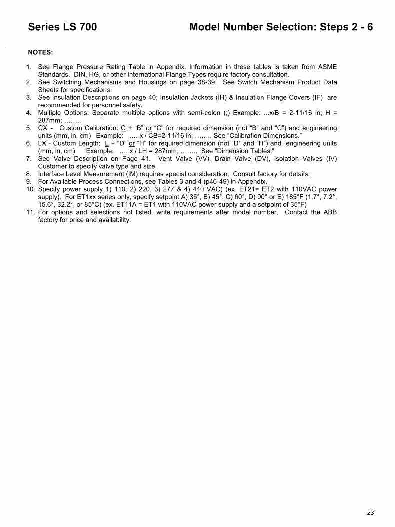
NOTES:
1. See Flange Pressure Rating Table in Appendix. Information in these tables is taken from ASME Standards. DIN, HG, or other International Flange Types require factory consultation.
2. See Switching Mechanisms and Housings on page 38-39. See Switch Mechanism Product Data Sheets for specifications.
3. See Insulation Descriptions on page 40; Insulation Jackets (IH) & Insulation Flange Covers are recommended for personnel safety.
4. Multiple Options: Separate multiple options with semi-colon (;) Example: ...x/B = 2-11/16 in; H = 287mm; ……..
5. CX - Custom Calibration: C + ―B‖ or ―C‖ for required dimension (not ―B‖ and ―C‖) and engineering units (mm, in, cm) Example: …. x / CB=2-11/16 in; …….. See ―Calibration Dimensions.‖
6. LX - Custom Length: L + ―D‖ or ―H‖ for required dimension (not ―D‖ and ―H‖) and engineering units (mm, in, cm) Example: …. x / LH = 287mm; …….. See ―Dimension Tables.‖
7. See Valve Description on Page 41. Vent Valve (VV), Drain Valve (DV), Isolation Valves (IV) Customer to specify valve type and size.
8. Interface Level Measurement (IM) requires special consideration. Consult factory for details. 9. For Available Process Connections, see Tables 3 and 4 (p46-49) in Appendix. 10. Chamber Access Flange Types will be the same as Process Connections. If Process Connections
are not flanges, Raised Face Slip-ons will be the standard (unless otherwise specified). Use option ―O‖ if flange type differs from process connection.
11. Specify power supply 1) 110, 2) 220, 3) 277 OR 4) 440 VAC) (ex. ET21= ET2 with 110VAC power supply). For ET1xx series only, specify setpoint A) 35°, B) 45°, C) 60°, D) 90° or E) 185°F (1.7°, 7.2°, 15.6°, 32.2°, or 85°C) (ex. ET11A = ET1 with 110VAC power supply and a setpoint of 35°F)
12. For options and selections not listed, write requirements after model number. Contact the ABB factory for price and availability.
Model Number Selection: Steps 2 - 6 Series LS 600

Calibration Dimensions for LS 600 series
1. ―B‖ is the distance that the switch trips on rising level at the specified S.G. 2. ―C‖ is the distance that the switch resets on falling level at the specified S.G. 3. The ―B‖ dimension is the default switch calibration setting. 4. The ―C‖ dimension will vary depending on the particular switch unit specified. 5. If a different ―B‖ or the ―C‖ dimension is required, it should be stated as shown under Options. 6. Calibration accuracy is +/- 1/4‖ (6mm)
600 Series 6x1
S.G. ―B‖ ―C‖
.54 2-11/16‖ 3-3/4‖
.60 3-3/16‖ 4-1/8‖
.70 3-3/4‖ 4-9/16‖
.80 4-3/16‖ 4-7/8‖
.90 4-9/16‖ 5-1/8‖
1.0 4-13/16‖ 5-3/8‖
600 Series 6x2
S.G. ―B‖ ―C‖
.64 2-9/16‖ 3-1/2‖
.70 3‖ 3-3/4‖
.80 3-1/2‖ 4-3/16‖
.90 3-15/16‖ 4-1/2‖
1.0 4-1/4‖ 4-3/4‖
1.1 4-1/2‖ 5‖
600 Series 6x3
S.G. ―B‖ ―C‖
.50 2-9/16‖ 3-3/8‖
.60 3-5/8‖ 4-1/16‖
.70 4-1/8‖ 4-7/16‖
.80 4-7/16‖ 4-3/4‖
.90 4-11/16‖ 4-15/16‖
1.1 4-7/8‖ 5-1/8‖
600 Series 6x4
S.G. ―B‖ ―C‖
.61 2-1/2‖ 3-1/4‖
.70 3-7/16‖ 3-13/16‖
.80 3-7/8‖ 4-3/16‖
.90 4-1/4‖ 4-1/2‖
1.0 4-1/2‖ 4-11/16‖
1.1 4-11/16‖ 4-7/8‖
600 Series 6x5
S.G. ―B‖ ―C‖
.38 3-1/4‖ 4-1/16‖
.40 3-13/16‖ 4-3/8‖
.50 5-1/16‖ 5-5/16‖
.60 5-11/16‖ 5-7/8‖
.70 6-1/16‖ 6-1/4‖
.80 6-3/8‖ 6-9/16‖
600 Series 6x6; 6x7
S.G. ―B‖ ―C‖
.65 2-1/16‖ 3-7/16‖
.70 2-3/8‖ 3-5/8‖
.80 2-3/4‖ 3-7/8‖
.90 3-1/8‖ 4-1/16‖
1.0 3-3/8‖ 4-1/4‖
1.1 3-9/16‖ 4-3/8‖
600 Series 6x8; 6x9
S.G. ―B‖ ―C‖
.93 2-5/8‖ 3-1/2‖
1.0 3‖ 3-3/4‖
1.1 3-7/16‖ 4-1/16‖
1.2 3-3/4‖ 4-3/8‖
1.3 4‖ 4-9/16‖
1.4 4-1/4‖ 4-13/16‖
Calibration Dimensions Series LS 600
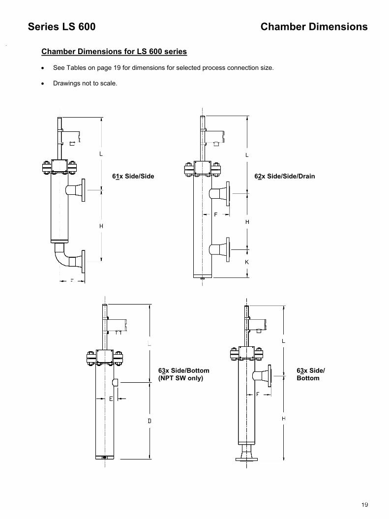
Chamber Dimensions for LS 600 series
See Tables on page 19 for dimensions for selected process connection size.
Drawings not to scale.
Chamber Dimensions Series LS 600
61x Side/Side 62x Side/Side/Drain
63x Side/Bottom
63x Side/Bottom (NPT SW only)

Dimension Tables 1” Process Connection Dimension Table
D* E* F H K L
Inches mm Inches mm inches mm inches mm inches mm inches mm
6x1 10-1/2 267 3-11/16 94 TBD
TBD
14 356 TBD TBD TBD TBD
6x2
6x3 10-3/8 264 4-3/4 121 TBD
TBD
14 356 TBD TBD TBD TBD
6x4
6x5 12 -5/8 321 5-3/4 146 TBD TBD 16 406 TBD TBD TBD TBD
6x6 9 229 3-3/16 81 TBD TBD 14 356 TBD TBD TBD TBD
6x7
6x8 10-1/2 267 3-11/16 94 TBD TBD 14 356 TBD TBD TBD TBD
D* E* F H K L
Inches mm Inches mm inches mm inches mm inches mm inches mm
6x1 10-9/16 268 3-3/4 95 TBD TBD 14 356 TBD TBD TBD TBD
6x2
6x3 10-7/16 265 4-13/16 122 TBD TBD 14 356 TBD TBD TBD TBD
6x4
6x5 12-11/16 322 5-13/16 148 TBD TBD 16 406 TBD TBD TBD TBD
6x6 9 229 3-1/4 83 TBD TBD 14 356 TBD TBD TBD TBD
6x7
6x8 10-9/16 268 3-3/4 95 TBD TBD 14 356 TBD TBD TBD TBD
D* E* F H K L
Inches mm Inches mm inches mm inches mm inches mm inches mm
6x1 10-11/16 271 3-7/8 98 TBD TBD 14 356 TBD TBD TBD TBD
6x2
6x3 10-9/16 268 4-15/16 125 TBD TBD 14 356 TBD TBD TBD TBD
6x4
6x5 12-13/16 325 5-15/16 151 TBD TBD 16 406 TBD TBD TBD TBD
6x6 -- NA-- -- NA-- --NA-- -- NA-- TBD TBD 14 356 TBD TBD TBD TBD
6x7
6x8 10-11/16 271 3-7/8 98 TBD TBD 14 356 TBD TBD TBD TBD
* These dimensions apply to Model 63x Side/Bottom with Threaded or Socket ―Flange Type‖ only (see p18)
Chamber Dimensions Series LS 600
* These dimensions apply to Model 63x Side/Bottom withThreaded or Socket ―Flange Type‖ only (see p18)
2” Process Connection Dimension Table
* These dimensions apply to Model 63x Side/Bottom withThreaded or Socket ―Flange Type‖ only (see p18)
1-1/2” Process Connection Dimension Table

A – Side/Side
Carbon Steel Chamber (A106 GrB)
Stainless Steel Chamber (316SS)
Step 1:
/a/ Select PROCESS CONNECTION CONFIGURATION
Consult ABB factory for other chamber materials and proc-ess conditions not listed.
Model Number Selection: Step 1 Series LS 700
Model Number Format
71x Side/Side 72x Side/Side/Drain 73x Side/Bottom
Sealed Chamber Float Series
Float materials: 316 SS (S6) is the standard. The following materials and others are avail-able. Hastelloy C276; Titanium Gr2 and Tita-nium Gr5. Construction materials are deter-mined by application specifics (i.e. tempera-ture, pressure and spe-cific gravity.
Series LS 7xx - Sealed Chamber Float
Series LS 73x - Side/Bottom Process Connections Example Application Data: Pressure 27bar, Temperature 35°C, S.G. 0.5, 35°C, S.G. 0.5, 1‖ Process Connection
Example:LS738/SS6/C1W3/SC13/B/X/LH=315mm
Model (Series) (a)
Chamber Material
(b)
Process Connection Size,
Type & Rating (c)
Switching Mechanism
Type (d)
Insulation (e)
Options (f)
738 SS6 C1W3/SC13 B X LH=315mm
Pressure at Indicated Temperature
Model Series
37.7° C (bar)
450° F (psig)
232° C (bar)
750° F (psig)
399° C (bar)
Float Mat'l Code
Minimum S.G.
100° F (psig)
1000°F (psig)
538°C (bar)
7x1 225 15.5 207 14.3 175 12.1 TBD .37 159 11.0
7x2 300 20.7 276 19.0 233 16.1 TBD .54 212 14.6
7x3 500 34.5 460 31.7 389 26.8 TBD .64 354 24.4
7x4 1250 86.2 1150 79.3 972 67.0 TBD .93 884 60.9
7x5 750 51.7 690 47.6 584 40.3 TBD .5 531 36.6
7x6 1000 68.9 920 63.4 778 53.6 TBD .63 708 48.8
7x7 1000 68.9 920 63.4 778 53.6 TBD .61 708 48.8
7x8 450 31.0 414 28.5 350 24.1 TBD .38 318 21.9
7x9 350 24.1 322 22.2 272 18.8 TBD .65 247 17.1
Pressure at Indicated Temperature
Model Series
37.7° C (bar)
450° F (psig)
232° C (bar)
750° F (psig)
399° C (bar)
Float Mat'l Code
Minimum S.G.
100° F (psig)
1000°F (psig)
538°C (bar)
7x1 225 15.5 207 14.3 175 12.1 TBD .37 159 11.0
7x2 300 20.7 276 19.0 233 16.1 TBD .54 212 14.6
7x3 500 34.5 460 31.7 389 26.8 TBD .64 354 24.4
7x4 1250 86.2 1052 72.5 972 67.0 TBD .93 847 58.4
7x5 750 51.7 690 47.6 584 40.3 TBD .5 531 36.6
7x6 1000 68.9 838 57.8 778 53.6 TBD .63 677 46.6
7x7 1000 68.9 838 57.8 778 53.6 TBD .61 677 46.6
7x8 450 31.0 414 28.5 350 24.1 TBD .38 318 21.9
7x9 350 24.1 322 22.2 272 18.8 TBD .65 247 17.1

Step 5:4 /e/ INSULATION3 X NO INSULATION IP INSULATION PAD - ALL SERVICES >180°F (82°C)
PNEUMATIC SWITCHES ONLY ALL SERVICES >300°F (149°C)
ELECTRIC SWITCHES ONLY IH1 HIGH TEMP. INSULATION;
FLOAT CHAMBER ONLY; 1/2‖THICK, 250°F (121°C) MAX IH1D HIGH TEMP. INSULATION;
FLOAT CHAMBER & VENT/ DRAIN FLANGES; 1/2‖THICK, 250°F (121°C) MAX IH2 HIGH TEMP. INSULATION;
FLOAT CHAMBER ONLY; 1‖THICK, 500°F (260°C) MAX IH2D HIGH TEMP. INSULATION;
FLOAT CHAMBER & VENT/ DRAIN FLANGES; 1‖THICK, 500°F (260°C) MAX IH3 HIGH TEMP. INSULATION;
FLOAT CHAMBER ONLY; 2‖THICK, 900°F (482°C) MAX IH3D HIGH TEMP. INSULATION;
FLOAT CHAMBER & VENT/ DRAIN FLANGES; 2‖THICK, 900°F (482°C) MAX
IL1 CRYOGENIC INSULATION;
2‖THICK; SINGLE LAYER; -100°F (-73°C) MINIMUM IL2 CRYOGENIC INSULATION;
3‖ THICK; DOUBLE LAYER; -200°F (-129°C) MINIMUM IL3 CRYOGENIC INSULATION;
4‖ THICK; DOUBLE LAYER; -320°F (-196°C) MINIMUM O CUSTOM11
OO
CUSTO
Step 2: /b/ CHAMBER MATERIAL CST CARBON STEEL (STANDARD) SS6 316 SS DUP DUPLEX STAINLESS STEEL HSB HASTELLOY B-3 HSC HASTELLOY C-276 P11 P11 1.25%CHROME,
MOLYBDENUM STEEL P91 P91 9% CHROME,
MOLYBDENUM STEEL O CUSTOM11
Step 3: /c/ PROCESS CONNECTION SIZE TYPE & RATING1,9
SEE TABLES 3 & 4 (p46-49) IN APPENDIX O CUSTOM11
Step 4:4
/d/ SWITCHING MECHANISM TYPE2 1 AMP SPDT REED SWITCH A MS30 B MS30EX 10AMP DPDT CAM ACTION SWITCH C MS40 D MS40/EX E MS41 HERM SEALED
(STANDARD) PNEUMATIC SWITCH F PS35 G PS45
Model Number Selection: Steps 2 - 6 Series LS 700
Step 6:4 /h/ OPTIONS X NO OPTIONS CX CUSTOM CALIBRATION5 LX CUSTOM CHAMBER LENGTH6 VV VENT VALVE7 DV DRAIN VALVE7
IV ISOLATION VALVE7
IM INTERFACE LEVEL MEASUREMENT8
TT1 STEAM TRACE TUBING ET1xx ELECTRIC TRACING; CLASS 1, DIV 2, GP BCD; 221°F(105°C) MAX,
FIXED SET POINT CONTROL10 ET2x ELECTRIC TRACING; CLASS 1, DIV 2, GP BCD;400°F(204°C) MAX ,
ADJUSTABLE SETPOINT CONTROL10 ET3x ELECTRIC TRACING; CLASS 1, DIV 2, GP BCD;800°F (427°C) MAX,
ADJUSTABLE SETPOINT CONTROL10 G GUSSETS ON PROCESS
CONNECTION (HIGH VIBRATION APPLICATIONS) O CUSTOM11
NOTE: REFERENCE MODEL NUMBER
SELECTION NOTES ON THE FOLLOWING PAGE
NOTES:
1. See Flange Pressure Rating Table in Appendix. Information in these tables is taken from ASME Standards. DIN, HG, or other International Flange Types require factory consultation.
2. See Switching Mechanisms and Housings on page 38-39. See Switch Mechanism Product Data Sheets for specifications.
3. See Insulation Descriptions on page 40; Insulation Jackets (IH) & Insulation Flange Covers (IF) are recommended for personnel safety.
4. Multiple Options: Separate multiple options with semi-colon (;) Example: ...x/B = 2-11/16 in; H = 287mm; ……..
5. CX - Custom Calibration: C + ―B‖ or ―C‖ for required dimension (not ―B‖ and ―C‖) and engineering units (mm, in, cm) Example: …. x / CB=2-11/16 in; …….. See ―Calibration Dimensions.‖
6. LX - Custom Length: L + ―D‖ or ―H‖ for required dimension (not ―D‖ and ―H‖) and engineering units (mm, in, cm) Example: …. x / LH = 287mm; …….. See ―Dimension Tables.‖
7. See Valve Description on Page 41. Vent Valve (VV), Drain Valve (DV), Isolation Valves (IV) Customer to specify valve type and size.
8. Interface Level Measurement (IM) requires special consideration. Consult factory for details. 9. For Available Process Connections, see Tables 3 and 4 (p46-49) in Appendix. 10. Specify power supply 1) 110, 2) 220, 3) 277 & 4) 440 VAC) (ex. ET21= ET2 with 110VAC power
supply). For ET1xx series only, specify setpoint A) 35°, B) 45°, C) 60°, D) 90° or E) 185°F (1.7°, 7.2°, 15.6°, 32.2°, or 85°C) (ex. ET11A = ET1 with 110VAC power supply and a setpoint of 35°F)
11. For options and selections not listed, write requirements after model number. Contact the ABB factory for price and availability.
Model Number Selection: Steps 2 - 6 Series LS 700

Calibration Dimensions for LS 700 series
1. ―B‖ is the distance that the switch trips on rising level at the specified S.G. 2. ―C‖ is the distance that the switch resets on falling level at the specified S.G. 3. The ―B‖ dimension is the default switch calibration setting. 4. The ―C‖ dimension will vary depending on the particular switch unit specified. 5. If a different ―B‖ or the ―C‖ dimension is required, it should be stated as shown under Options. 6. Calibration accuracy is +/- 1/4‖ (6mm)
700 Series 7x1
S.G. "B" "C"
0.37 2-5/16" 3-1/2"
0.40 3" 3-3/4"
0.50 3-15/16" 4-3/8"
0.60 4-3/8" 4-3/4"
0.70 4-3/4" 5-1/16"
0.80 4-15/16" 5-1/4"
700 Series 7x2
S.G. "B" "C"
0.54 2-11/16" 3-3/4"
0.60 3-3/16" 4-1/8"
0.70 3-3/4" 4-9/16"
0.80 4-3/16" 4-7/8"
0.90 4-9/16" 5-1/8"
1.0 4-13/16" 5-3/8"
700 Series 7x3
S.G. "B" "C"
0.64 2-9/16" 3-1/2"
0.70 3" 3-3/4"
0.80 3-1/2" 4-13/16"
0.90 3-15/16" 4-1/2"
1.0 4-1/4" 4-3/4"
1.1 4-1/2" 5"
700 Series 7x4
S.G. "B" "C"
0.93 2-5/8" 3-1/2"
1.0 3" 3-3/4"
1.1 3-7/16" 4-1/16"
1.2 3-3/4" 4-3/8"
1.3 4" 4-9/16"
1.4 4-1/4" 4-13/16"
700 Series7x7
S.G. "B" "C"
0.61 2-1/2" 3-1/4"
0.7 3-7/16" 3-13/16"
0.8 3-15/16" 4-3/16"
0.9 4-1/4" 4-1/2"
1.0 4-1/2" 4-3/4"
1.1 4-11/16" 4-7/8"
700 Series 7x8
S.G. "B" "C"
0.38 3-1/4" 4-1/16"
0.40 3-13/16" 4-3/8"
0.50 5-1/16" 5-5/16"
0.60 5-11/16" 5-7/8"
0.70 6-1/16" 6-1/4"
0.80 6-3/8" 6-9/16"
Calibration Dimensions Series LS 700
700 Series 7x5
S.G. "B" "C"
0.50 2-9/16" 3-3/8"
0.60 3-5/8" 4-1/16"
0.70 4-1/8" 4-7/16"
0.80 4-7/16" 4-3/4"
0.90 4-11/16" 4-15/16"
1.0 4-7/8" 5-1/8"
700 Series 7x6
S.G. "B" "C"
0.63 2-5/8" 3-3/4"
0.70 3-7/16" 4-1/16"
0.80 3-7/8" 4-3/8"
0.90 4-3/16" 4-9/16"
1.0 4-7/16" 4-3/4"
1.1 4-5/8" 4-7/8"
700 Series7x9
S.G. "B" "C"
0.65 2-1/16" 3-7/16"
0.70 2-3/8" 3-5/8"
0.80 2-3/4" 3-7/8"
0.90 3-1/8" 4-1/16"
1.0 3-3/8" 4-1/4"
1.1 3-9/16" 4-3/8"

Chamber Dimensions for LS 700 series
See Tables on page 25 for dimensions for selected process connection size.
Drawings not to scale.
Chamber Dimensions Series LS 700
71x Side/Side 72x Side/Side/Drain
73x Side/Bottom
73x Side/Bottom (NPT SW only)

Dimension Tables
D* E* F H K L
inches mm inches mm inches mm inches mm inches mm inches mm
7x1 10-7/16
265 4-13-16 122 TBD TBD 14 356 TBD TBD TBD TBD 7x2
7x3 10-9/16
268 3-3/4 95 TBD TBD 14 356 TBD TBD TBD TBD 7x4
7x5 10-7/16
265 4-13/16 122 TBD TBD 14 356 TBD TBD TBD TBD
7x6 10-7/16
265 4-13/16 122 TBD TBD 14 356 TBD TBD TBD TBD 7x7
7x8 12-
11/16 322 5-13/16 147 TBD TBD 16 406 TBD TBD TBD TBD
D* E* F H K L
inches mm inches mm inches mm inches mm inches mm inches mm
7x1 10-9/16 269 4-15/16 126 TBD TBD 14 356 TBD TBD TBD TBD
7x2
7x3 10-11/16 273 3-7/8 99 TBD TBD 14 356 TBD TBD TBD TBD
7x4
7x5 10-9/16 269 4-15/16 126 TBD TBD 14 356 TBD TBD TBD TBD
7x6 10-9/16 269 4-15/16 126 TBD TBD 14 356 TBD TBD TBD TBD
7x7
7x8 12-13/16 326 5-15/16 151 TBD TBD 16 406 TBD TBD TBD TBD
Chamber Dimensions Series LS 700
D* E* F H K L
inches mm inches mm inches mm inches mm inches mm inches mm
7x1 10-3/8 264 4-3/4 121 TBD TBD 14 356 TBD TBD TBD TBD
7x2
10-1/2 267 3-11/16 94 TBD TBD 14 356 TBD TBD TBD TBD 7x3
7x4
7x5
10-3/8 264 4-3/4 121 TBD TBD 14 356 TBD TBD TBD TBD 7x6
7x7
7x8 12-5/8 321 5-3/4 146 TBD TBD 16 406 TBD TBD TBD TBD
7x9 9 229 3-3/16 81 TBD TBD 14 356 TBD TBD TBD TBD
1-1/2” Process Connection Dimension Table
2” Process Connection Dimension Table
1” Process Connection Dimension Table
* These dimensions apply to Model 63x Side/Bottom with Threaded or Socket ―Flange Type‖ only (see p.24)
* These dimensions apply to Model 63x Side/Bottom with Threaded or Socket ―Flange Type‖ only (see p.24)
* These dimensions apply to Model 63x Side/Bottom with Threaded or Socket ―Flange Type‖ only (see p.24)

A – Side/Side
Carbon Steel Chamber (A106 GrB)
Stainless Steel Chamber (316SS)
Step 1:
Consult ABB factory for other chamber materials and process conditions not listed.
Model Number Selection: Step 1 Series LS 800
Pressure at Indicated Temperature
Model Series
100° F (psig)
37.7° C (bar)
450° F (psig)
Float Mat'l Code
Minimum S.G.
232° C (bar)
8x1 285 19.7 185 12.8 S6 .4
8x2 740 51.0 618 42.6 S6 .4
8x3 1480 102.0 1235 85.2 S6 .4
8x4 3376 232.8 3083 212.6 S6 .4
Standard displacer units are not available above 450°F (232°C)
Pressure at Indicated Temperature
Model Series
37.7° C (bar)
450° F (psig)
232° C (bar)
Float Mat'l Code
Minimum S.G.
100° F (psig)
8x1 275 19.0 182 12.5 S6 .4
8x2 720 49.6 497 34.3 S6 .4
8x3 1440 99.3 992 68.4 S6 .4
8x4 3600 248.2 2480 171.0 S6 .4
Standard displacer units are not available above 450°F (232°C)
Model Number Formats
81x Side/Side 82x Side/Side/Drain 83x Side/Bottom
Flanged Chamber Displacer Series
Series LS 8xx - Flanged Chamber Displacer
82x - Side / Side/ Drain Process Connections Example Application Data: Pressure 150bar, Temperature 35°C, S.G. 0.5 35°C, S.G. 0.5, 3 ‖ Flange Process Connection
Example: LS824/SS6/GEGE/SJ315/D/IH2D/CB=2-11/16”
Model (Series) (a)
Chamber Material
(b)
Process Connection Size,
Type & Rating (c)
Switching Mechanism
Type (d)
Insulation (e)
Options (f)
824 SS6 GEGE/SJ315 D IH2D CB=2-11/16”
Displacer Materials: 316 SS (S6) is the standard. The fol-lowing materials and others are available. Hastelloy C276; Ti-tanium Gr2, Titanium Gr5 and Porcelain. Construction materi-als are determined by applica-tion specifics (i.e. temperature, pressure and specific gravity).

Step 5:4 /e/ INSULATION3 X NO INSULATION IP INSULATION PAD - ALL SERVICES >180°F (82°C)
PNEUMATIC SWITCHES ONLY ALL SERVICES >300°F (149°C)
ELECTRIC SWITCHES ONLY IH1 HIGH TEMP. INSULATION;
FLOAT CHAMBER ONLY; 1/2‖THICK, 250°F (121°C) MAX IH1D HIGH TEMP. INSULATION;
FLOAT CHAMBER & VENT/ DRAIN FLANGES; 1/2‖THICK, 250°F (121°C) MAX IH2 HIGH TEMP. INSULATION;
FLOAT CHAMBER ONLY; 1‖THICK, 500°F (260°C) MAX IH2D HIGH TEMP. INSULATION;
FLOAT CHAMBER & VENT/ DRAIN FLANGES; 1‖THICK, 500°F (260°C) MAX IH3 HIGH TEMP. INSULATION;
FLOAT CHAMBER ONLY; 2‖THICK, 900°F (482°C) MAX IH3D HIGH TEMP. INSULATION;
FLOAT CHAMBER & VENT/ DRAIN FLANGES; 2‖THICK, 900°F (482°C) MAX
IF INSULATION FLANGE - RATED UP TO 900°F (482°C) MAX IL1 CRYOGENIC INSULATION;
2‖THICK; SINGLE LAYER; -100°F (-73°C) MINIMUM IL2 CRYOGENIC INSULATION;
3‖ THICK; DOUBLE LAYER; -200°F (-129°C) MINIMUM IL3 CRYOGENIC INSULATION;
4‖ THICK; DOUBLE LAYER; -320°F (-196°C) MINIMUM O CUSTOM12
Step 2: /b/ CHAMBER MATERIAL CST CARBON STEEL (STANDARD) SS6 316 SS DUP DUPLEX STAINLESS STEEL HSB HASTELLOY B-3 HSC HASTELLOY C-276 P11 P11 1.25%CHROME,
MOLYBDENUM STEEL P91 P91 9% CHROME,
MOLYBDENUM STEEL O CUSTOM11
Step 3: /c/ PROCESS CONNECTION SIZE
TYPE & RATING1,9, 10
SEE TABLES 3 & 4 (p46-49) IN APPENDIX O CUSTOM12
Step 4:4
/d/ SWITCHING MECHANISM TYPE2 10 AMP DPDT CAM ACTION SWITCH C MS40 D MS40/EX E MS41 HERM SEALED
(STANDARD) PNEUMATIC SWITCH F PS35 G PS45
Model Number Selection: Steps 2 - 6 Series LS 800
Step 6:4 /h/ OPTIONS X NO OPTIONS CX CUSTOM CALIBRATION5 LX CUSTOM CHAMBER LENGTH6 VV VENT VALVE7 DV DRAIN VALVE7
IV ISOLATION VALVE7
IM INTERFACE LEVEL MEASUREMENT8
TT1 STEAM TRACE TUBING ET1xx ELECTRIC TRACING; CLASS 1, DIV 2, GP BCD; 221°F(105°C) MAX,
FIXED SET POINT CONTROL11 ET2x ELECTRIC TRACING; CLASS 1, DIV 2, GP BCD;400°F (204°C) MAX,
ADJUSTABLE SETPOINT CONTROL11 ET3x ELECTRIC TRACING; CLASS 1, DIV 2, GP BCD;800°F (427°C) MAX,
ADJUSTABLE SETPOINT CONTROL11 G GUSSETS ON PROCESS
CONNECTION (HIGH VIBRATION APPLICATIONS) O CUSTOM12
NOTE: REFERENCE MODEL NUMBER
SELECTION NOTES ON THE FOLLOWING PAGE

Model Number Selection: Steps 2 - 6 Series LS 800
NOTES:
1. See Flange Pressure Rating Table in Appendix. Information in these tables is taken from ASME Standards. DIN, HG, or other International Flange Types require factory consultation.
2. See Switching Mechanisms and Housings on page 38-39. See Switch Mechanism Product Data Sheets for specifications.
3. See Insulation Descriptions on page 40; Insulation Jackets (IH) & Insulation Flange Covers are recommended for personnel safety.
4. Multiple Options: Separate multiple options with semi-colon (;) Example: ...x/B = 2-11/16 in; H = 287mm; ……..
5. CX - Custom Calibration: C + ―B‖ or ―C‖ for required dimension (not ―B‖ and ―C‖) and engineering units (mm, in, cm) Example: …. x / CB=2-11/16 in; …….. See ―Calibration Dimensions.‖
6. LX - Custom Length: L + ―D‖ or ―H‖ for required dimension (not ―D‖ and ―H‖) and engineering units (mm, in, cm) Example: …. x / LH = 287mm; …….. See ―Dimension Tables.‖
7. See Valve Description on Page 41. Vent Valve (VV), Drain Valve (DV), Isolation Valves (IV) Customer to specify valve type and size.
8. Interface Level Measurement (IM) requires special consideration. Consult factory for details. 9. For Available Process Connections, see Tables 3 and 4 (p46-49) in Appendix. 10. Chamber Access Flange Types will be the same as Process Connections. If Process Connections
are not flanges, Raised Face Slip-Ons will be the standard (unless otherwise specified). 11. Specify power supply 1) 110, 2) 220, 3) 277 or 4) 440 VAC) (ex. ET21= ET2 with 110VAC power
supply). For ET1xx series only, specify setpoint A) 35°, B) 45°, C) 60°, D) 90° or E) 185°F (1.7°, 7.2°, 15.6°, 32.2°, or 85°C) (ex. ET11A = ET1 with 110VAC power supply and a setpoint of 35°F)
12. For options and selections not listed, write requirements after model number. Contact the ABB factory for price and availability.

Calibration Dimensions for LS 800 series
1. ―B‖ is the distance that the switch trips on rising level at the specified S.G. 2. ―C‖ is the distance that the switch resets on falling level at the specified S.G. 3. The ―B‖ dimension is the default switch calibration setting. 4. The ―C‖ dimension will vary depending on the particular switch unit specified. 5. If a different ―B‖ or the ―C‖ dimension is required, it should be stated as shown under Options. 6. Calibration accuracy is +/- 1/4‖ (6mm)
800 Series 8x1
S.G. "B" "C"
0.40 1-3/8" 4-7/16"
0.50 2-7/16" 5"
0.60 3-1/8" 5-5/16"
0.70 3-11/16" 5-9/16"
0.80 4-1/16" 5-3/4"
0.90 4-15/16" 5-15/16"
800 Series 8x4
S.G. "B" "C"
0.40 2-15/16" 5-1/4"
0.50 3-3/4" 5-5/8"
0.60 4-5/16" 5-15/16"
0.70 4-11/16" 6-1/8"
0.80 5" 6-1/4"
0.90 5-3/16" 6-3/8"
Calibration Dimensions Series LS 800
800 Series 8x2
S.G. "B" "C"
0.40 1-3/8" 4-7/16"
0.50 2-7/16" 5"
0.60 3-1/8" 5-5/16"
0.70 3-11/16" 5-9/16"
0.80 4-1/16" 5-3/4"
0.90 4-15/16" 5-15/16"
800 Series 8x3
S.G. "B" "C"
0.40 1-3/8" 4-7/16"
0.50 2-7/16" 5"
0.60 3-1/8" 5-5/16"
0.70 3-11/16" 5-9/16"
0.80 4-1/16" 5-3/4"
0.90 4-15/16" 5-15/16"

Chamber Dimensions for LS 800 series
See Tables on page 31 for dimensions for selected process connection size.
Drawings not to scale.
Chamber Dimensions Series LS 800
81x Side/Side 82x Side/Side/Drain
83x Side/Bottom
83x Side/Bottom (NPT SW only)

Dimension Tables 1” Process Connection Dimension Table
Chamber Dimensions Series LS 800
D* E* F H K L
inches mm inches mm inches mm inches mm inches mm inches mm
8x1
13 330 3-3/16 81 TBD TBD 16 406 TBD TBD TBD TBD 8x2
8x3
8x4 11-1/2 292 3-11/16 94 TBD TBD 16 406 TBD TBD TBD TBD
8x5 12-3/4 324 3-15/16 100 TBD TBD 16 406 TBD TBD TBD TBD
D* E* F H K L
inches mm inches mm inches mm inches mm inches mm inches mm
8x1
13 330 3-1/4 82 TBD TBD 16 406 TBD TBD TBD TBD 8x2
8x3
8x4 11-9/16 294 3-3/4 95 TBD TBD 16 406 TBD TBD TBD TBD
8x5 12-7/8 327 4-1/16 103 TBD TBD 16 406 TBD TBD TBD TBD
D* E* F H K L
inches mm inches mm inches mm inches mm inches mm inches mm
8x1
TBD TBD 16 406 TBD TBD TBD TBD 8x2
8x3
8x4 11-11/16 297 3-7/8 98 TBD TBD 16 406 TBD TBD TBD TBD
8x5 13-1/4 337 4-7/16 113 TBD TBD 16 406 TBD TBD TBD TBD
1-1/2” Process Connection Dimension Table
2” Process Connection Dimension Table
* These dimensions apply to Model 63x Side/Bottom with Threaded or Socket ―Flange Type‖ only (see p.30)
* These dimensions apply to Model 63x Side/Bottom with Threaded or Socket ―Flange Type‖ only (see p.30)
* These dimensions apply to Model 63x Side/Bottom with Threaded or Socket ―Flange Type‖ only (see p.30)
A – Side/Side
Carbon Steel Chamber (A106 GrB)
Stainless Steel Chamber (316SS)
Step 1:
/a/ Select PROCESS CONNECTION CONFIGURATION.
Consult ABB factory for other chamber materials and process conditions not listed.
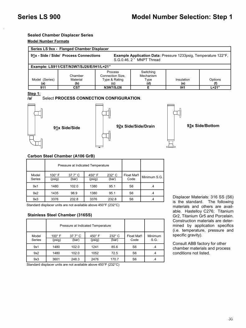
Model Number Selection: Step 1 Series LS 900
Standard displacer units are not available above 450°F (232°C)
Pressure at Indicated Temperature
Model Series
100° F (psig)
37.7° C (bar)
450° F (psig)
Float Mat'l Code
Minimum S.G. 232° C (bar)
9x1 1480 102.0 1380 95.1 S6 .4
9x2 1435 98.9 1380 95.1 S6 .4
9x3 3376 232.8 3376 232.8 S6 .4
Pressure at Indicated Temperature
Model Series
37.7° C (bar)
450° F (psig)
232° C (bar)
Float Mat'l Code
Minimum S.G.
100° F (psig)
9x1 1480 102.0 1241 85.6 S6 .4
9x2 1480 102.0 1052 72.5 S6 .4
9x3 3601 248.3 2476 170.7 S6 .4
Standard displacer units are not available above 450°F (232°C)
Model Number Formats
91x Side/Side 92x Side/Side/Drain 93x Side/Bottom
Sealed Chamber Displacer Series
Series LS 9xx - Flanged Chamber Displacer
91x - Side / Side/ Process Connections Example Application Data: Pressure 1233psig, Temperature 122°F, S.G. 0.5 S.G.0.46, 2 ‖ MNPT Thread
Example: LS911/CST/N3W7/SJ26/E/IH1/L=21”
Model (Series) (a)
Chamber Material
(b)
Process Connection Size,
Type & Rating (c)
Switching Mechanism
Type (d)
Insulation (e)
Options (f)
911 CST N3W7/SJ26 E IH1 L=21”
Displacer Materials: 316 SS (S6) is the standard. The following materials and others are avail-able. Hastelloy C276; Titanium Gr2, Titanium Gr5 and Porcelain. Construction materials are deter-mined by application specifics (i.e. temperature, pressure and specific gravity).
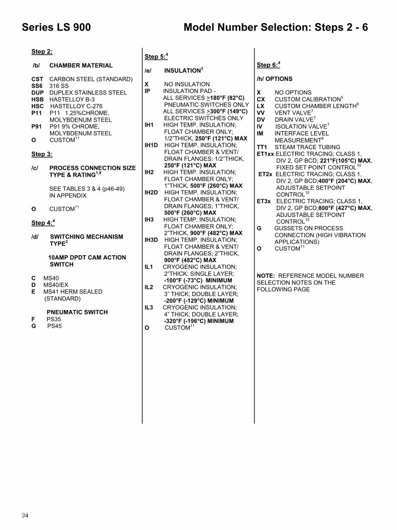
Step 5:4 /e/ INSULATION3 X NO INSULATION IP INSULATION PAD - ALL SERVICES >180°F (82°C)
PNEUMATIC SWITCHES ONLY ALL SERVICES >300°F (149°C)
ELECTRIC SWITCHES ONLY IH1 HIGH TEMP. INSULATION;
FLOAT CHAMBER ONLY; 1/2‖THICK, 250°F (121°C) MAX IH1D HIGH TEMP. INSULATION;
FLOAT CHAMBER & VENT/ DRAIN FLANGES; 1/2‖THICK, 250°F (121°C) MAX IH2 HIGH TEMP. INSULATION;
FLOAT CHAMBER ONLY; 1‖THICK, 500°F (260°C) MAX IH2D HIGH TEMP. INSULATION;
FLOAT CHAMBER & VENT/ DRAIN FLANGES; 1‖THICK, 500°F (260°C) MAX IH3 HIGH TEMP. INSULATION;
FLOAT CHAMBER ONLY; 2‖THICK, 900°F (482°C) MAX IH3D HIGH TEMP. INSULATION;
FLOAT CHAMBER & VENT/ DRAIN FLANGES; 2‖THICK, 900°F (482°C) MAX
IL1 CRYOGENIC INSULATION;
2‖THICK; SINGLE LAYER; -100°F (-73°C) MINIMUM IL2 CRYOGENIC INSULATION;
3‖ THICK; DOUBLE LAYER; -200°F (-129°C) MINIMUM IL3 CRYOGENIC INSULATION;
4‖ THICK; DOUBLE LAYER; -320°F (-196°C) MINIMUM O CUSTOM11
OO
CUSTO
Step 2: /b/ CHAMBER MATERIAL CST CARBON STEEL (STANDARD) SS6 316 SS DUP DUPLEX STAINLESS STEEL HSB HASTELLOY B-3 HSC HASTELLOY C-276 P11 P11 1.25%CHROME,
MOLYBDENUM STEEL P91 P91 9% CHROME,
MOLYBDENUM STEEL O CUSTOM11
Step 3: /c/ PROCESS CONNECTION SIZE
TYPE & RATING1,9
SEE TABLES 3 & 4 (p46-49) IN APPENDIX O CUSTOM11
Step 4:4
/d/ SWITCHING MECHANISM TYPE2 10AMP DPDT CAM ACTION SWITCH C MS40 D MS40/EX E MS41 HERM SEALED
(STANDARD) PNEUMATIC SWITCH F PS35 G PS45
Model Number Selection: Steps 2 - 6 Series LS 900
Step 6:4 /h/ OPTIONS X NO OPTIONS CX CUSTOM CALIBRATION5 LX CUSTOM CHAMBER LENGTH6 VV VENT VALVE7 DV DRAIN VALVE7
IV ISOLATION VALVE7
IM INTERFACE LEVEL MEASUREMENT8
TT1 STEAM TRACE TUBING ET1xx ELECTRIC TRACING; CLASS 1, DIV 2, GP BCD; 221°F(105°C) MAX,
FIXED SET POINT CONTROL10 ET2x ELECTRIC TRACING; CLASS 1, DIV 2, GP BCD;400°F (204°C) MAX,
ADJUSTABLE SETPOINT CONTROL10 ET3x ELECTRIC TRACING; CLASS 1, DIV 2, GP BCD;800°F (427°C) MAX,
ADJUSTABLE SETPOINT CONTROL10 G GUSSETS ON PROCESS
CONNECTION (HIGH VIBRATION APPLICATIONS) O CUSTOM11
NOTE: REFERENCE MODEL NUMBER
SELECTION NOTES ON THE FOLLOWING PAGE

Model Number Selection: Steps 2 - 6 Series LS 900
NOTES:
1. See Flange Pressure Rating Table in Appendix. Information in these tables is taken from ASME Standards. DIN, HG, or other International Flange Types require factory consultation.
2. See Switching Mechanisms and Housings on page 38 and 39. See Switch Mechanism Product Data Sheets for specifications.
3. See Insulation Descriptions on page 40; Insulation Jackets (IH) & Insulation Flange Covers (IF) are recommended for personnel safety.
4. Multiple Options: Separate multiple options with semi-colon (;) Example: ...x/B = 2-11/16 in; H = 287mm; ……..
5. CX - Custom Calibration: C + ―B‖ or ―C‖ for required dimension (not ―B‖ and ―C‖) and engineering units (mm, in, cm) Example: …. x / CB=2-11/16 in; …….. See ―Calibration Dimensions.‖
6. LX - Custom Length: L + ―D‖ or ―H‖ for required dimension (not ―D‖ and ―H‖) and engineering units (mm, in, cm) Example: …. x / LH = 287mm; …….. See ―Dimension Tables.‖
7. See Valve Description on Page 41. Vent Valve (VV), Drain Valve (DV), Isolation Valves (IV) Customer to specify valve type and size.
8. Interface Level Measurement (IM) requires special consideration. Consult factory for details. 9. For Available Process Connections, see Tables 3 and 4 (p46-49) in Appendix. 10. Specify power supply 1) 110, 2) 220, 3) 277 or 4) 440 VAC) (ex. ET21= ET2 with 110VAC power
supply). For ET1xx series only, specify setpoint A) 35°, B) 45°, C) 60°, D) 90° or E) 185°F (1.7°, 7.2°, 15.6°, 32.2°, or 85°C) (ex. ET11A = ET1 with 110VAC power supply and a setpoint of 35°F)
11. For options and selections not listed, write requirements after model number. Contact the ABB factory for price and availability.

Calibration Dimensions for LS 900 series
1. ―B‖ is the distance that the switch trips on rising level at the specified S.G. 2. ―C‖ is the distance that the switch resets on falling level at the specified S.G. 3. The ―B‖ dimension is the default switch calibration setting. 4. The ―C‖ dimension will vary depending on the particular switch unit specified. 5. If a different ―B‖ or the ―C‖ dimension is required, it should be stated as shown under Options. 6. Calibration accuracy is +/- 1/4‖ (6mm)
900 Series 9x1
S.G. "B" "C"
0.40 1-3/8" 4-7/16"
0.50 2-7/16" 5"
0.60 3-1/8" 5-5/16"
0.70 3-11/16" 5-9/16"
0.80 4-1/16" 5-3/4"
0.90 4-15/16" 5-15/16"
Calibration Dimensions Series LS 900
900 Series 9x3
S.G. "B" "C"
0.40 2-15/16" 5-1/4"
0.50 3-3/4" 5-5/8"
0.60 4-5/16" 5-15/16"
0.70 4-11/16" 6-1/8"
0.80 5" 6-1/4"
0.90 5-3/16" 6-3/8"
900 Series 9x2
S.G. "B" "C"
0.40 1-3/8" 4-7/16"
0.50 2-7/16" 5"
0.60 3-1/8" 5-5/16"
0.70 3-11/16" 5-9/16"
0.80 4-1/16" 5-3/4"
0.90 4-15/16" 5-15/16"
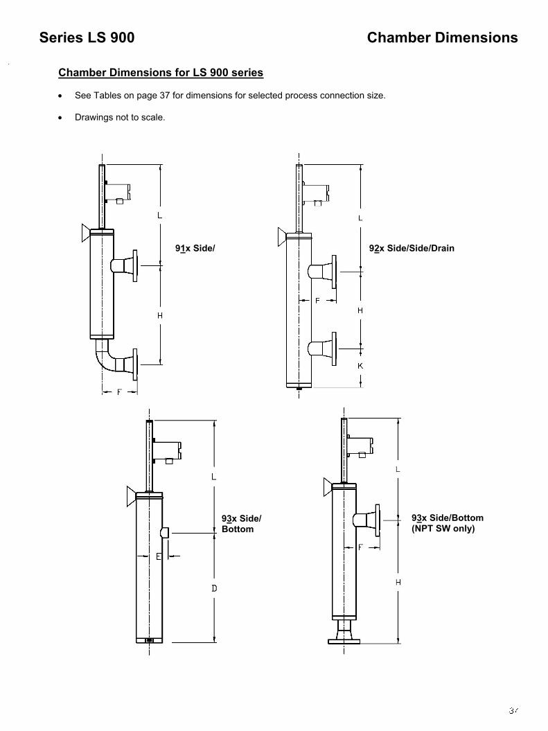
Chamber Dimensions for LS 900 series
See Tables on page 37 for dimensions for selected process connection size.
Drawings not to scale.
Chamber Dimensions Series LS 900
91x Side/ 92x Side/Side/Drain
93x Side/Bottom
93x Side/Bottom (NPT SW only)

Dimension Tables
Chamber Dimensions Series LS 900
D* E* F H K L
inches mm inches mm inches mm inches mm inches mm inches mm
9x1 13 330 3-3/16 81 TBD TBD 16 406 TBD TBD TBD TBD
9x2 11-1/2 292 3-11/16 94 TBD TBD 16 406 TBD TBD TBD TBD
9x3 12-3/4 324 3-15/16 100 TBD TBD 16 406 TBD TBD TBD TBD
D* E* F H K L
inches mm inches mm inches mm inches mm inches mm inches mm
9x1 13 330 3-1/4 82 TBD TBD 16 406 TBD TBD TBD TBD
9x2 11-9/16 294 3-3/4 95 TBD TBD 16 406 TBD TBD TBD TBD
9x3 12-7/8 327 4-1/16 103 TBD TBD 16 406 TBD TBD TBD TBD
D* E* F H K L
inches mm inches mm inches mm inches mm inches mm inches mm
9x1 TBD TBD 16 406 TBD TBD TBD TBD
9x2 11-11/16 297 3-7/8 99 TBD TBD 16 406 TBD TBD TBD TBD
9x3 13-1/4 337 4-7/16 113 TBD TBD 16 406 TBD TBD TBD TBD
1” Process Connection Dimension Table
1-1/2” Process Connection Dimension Table
2” Process Connection Dimension Table
* These dimensions apply to Model 63x Side/Bottom with Threaded or Socket ―Flange Type‖ only (see p.36)
* These dimensions apply to Model 63x Side/Bottom with Threaded or Socket ―Flange Type‖ only (see p.36)
* These dimensions apply to Model 63x Side/Bottom with Threaded or Socket ―Flange Type‖ only (see p.36)

The switch point of LS Series level switches is dependent upon the specific gravity of the process fluid and other fac-tors. As specific gravity decreases, the distance between the centerline of the upper process connection and the fluid level at which the switch transfers decreases. This is due to the additional amount of fluid required to make the float buoyant at the lower specific gravity. This means that actual fluid levels at the switch transfer point vary with specific gravity. The function of the LS Series level switch depends upon the movement of a magnet assembly within the switch post to activate an external switch. In order to begin moving up with rising fluid level, a small amount of static friction must be overcome. To facilitate this additional force, the floats are designed with reserve buoyancy to provide force for movement and to provide buoyancy with deceases in specific gravity. This reserve buoyancy is in the form of the amount of float that is above the fluid level. In order for the reserve buoyancy to be useful, it must be located where fluid may actually reach it. As a standard, we design the floats so that the top is even with the centerline of the upper process connection when the magnet assembly is all the way to the top of the sensor tube. This allows standardiza-tion of all chambers for manufacturing. The fluid level at switching is then a function of the specific gravity and the float selected. Dead-band of a magnetically operated switch is the distance a magnet must travel to transfer from one state to an-other. Switch transfer dead-band is a function of the type of switch selected and the strength of the magnetic field. The reed switch variety have only a small dead-band, while the cam actuated switches have larger dead-bands. Be-cause the dead-band is different for each switch type, we set LS Series switches to either the High (rising fluid (standard)) or the Low (falling fluid) reference point on the LS Series sensor tube per the customer‘s requirements. The operation of the switch in the opposite direction is the dead-band distance. The location of the on/off points for each type of switch is consistent for that type, and is therefore known and placed on the sensor tube at the reference point on the sensor tube. The LS Series is constructed such that sufficient over-travel past the switch point occurs to ensure proper operation no matter what switch type is used. This allowed over-travel increases the distance from the centerline of the upper process connection to the fluid level at the high switch point. This value is fixed at 11/16‖ for existing switch require-ments. A difference of 13/16‖ between the high and low reference points has also been established due to existing switch requirements. Therefore, the high switch point is determined by the 11/16‖ over-travel plus the length of the float above the fluid level at the specific gravity specified. The low switch point is determined by the 11/16‖ over-travel plus the 13/16‖ difference between the reference points and the length of the float above the fluid level at the specific gravity specified. The following ―magnetically activated‖ switching mechanisms in Table 1 are available and ready for use with the LS Series Switches. This table provides details on specific switching mechanism applicability. All switching mechanisms are available with the European CE mark. Consult the KTEK factory for certification/documentation. In high corrosive applications, ABB recommends the use of stainless steel housings over aluminum enclosures. Please see product data sheets on the KTEK website at www.ktekcorp.com for the latest specifications and approvals.
Switching Mechanisms & Housings Mechanical Level Switches

Switching Mechanisms & Housings Mechanical Level Switches
Mo
de
l
#
En
clo
su
re
S
wit
ch
ing
Mech
an
ism
Ap
pli
cati
on
Ag
en
cy
Ap
pro
vals
Typ
e
Rati
ng
s
Ele
ctr
ical
Co
nn
ecti
on
T
yp
e
Rati
ng
s
Min
Pro
cess
Tem
p
Max P
roc
ess
Tem
p
Dead
-b
an
d
Co
nta
cts
H
igh
T
em
p V
ibra
tio
n
Hig
h
Co
rro
-sio
n
MS
30
FM
, C
SA
H
erm
eti
call
y
Seale
d
NE
MA
4x
1/2
” M
NP
T
Reed
A
C/D
C
1am
p
-40°F
(-4
0°C
)
300°F
(149°C
);
600°F
(316°C
) w
ith
IP
op
tio
n
1/8
”
SP
DT
●
MS
30/E
X
FM
, C
SA
H
erm
eti
call
y
Seale
d,
Exp
losio
n P
roo
f
NE
MA
4x
1/2
” F
NP
T
Reed
A
C/D
C
1am
p
-40°F
(-4
0°C
)
300°F
(149°C
);
600°F
(316°C
) w
ith
IP
op
tio
n
1/8
”
SP
DT
●
MS
40
FM
, C
SA
S
tain
less S
teel
NE
MA
4x
1/2
” F
NP
T
Cam
Dri
ven
, S
na
p A
cti
on
A
C:1
0am
p
DC
: 2.6
am
p
-60°F
(-5
1°C
)
300°F
(149°C
);
600°F
(316°C
) w
ith
IP
op
tio
n
7/8
”
DP
DT
●
●
●
MS
40/E
X
FM
, C
SA
S
tain
less S
teel,
Exp
losio
n P
roo
f N
EM
A 4
x
3/4
” F
NP
T
Cam
Dri
ven
, S
na
p A
cti
on
A
C:1
0am
p
DC
:1/2
am
p
-60°F
(-5
1°C
)
300°F
(149°C
);
600°F
(316°C
) w
ith
IP
op
tio
n
13/1
6”
DP
DT
●
●
●
MS
41
FM
, C
SA
, A
TE
X
Sta
inle
ss S
teel,
Du
al
Co
mp
art
-m
en
t,
Herm
eti
call
y
Seale
d,
Exp
losio
n P
roo
f
NE
MA
4x
1/2
” F
NP
T
Cam
Dri
ven
, S
na
p A
cti
on
A
C:
10am
p
DC
: 2.6
am
p
-320°F
(-1
95°C
)w
ith
op
tio
n
300°F
(149°C
);
1000°F
(538°C
) w
ith
IP
op
tio
n
15/1
6”
DP
DT
●
●
●
PS
35
No
n-e
lectr
ic
Sta
inle
ss S
teel
NE
MA
4x
1/8
” M
NP
T
po
rt
Pn
eu
mati
c
15 t
o 1
00
ps
ig
0°F
(-1
8°C
)
180°F
(82°C
);
450°F
(232°C
) w
ith
IP
op
tio
n
1”
Pn
eu
-m
ati
c
Sig
na
l
●
PS
45
No
n-e
lectr
ic
Sta
inle
ss S
teel
NE
MA
4x
1/8
” M
NP
T
po
rt
Pn
eu
mati
c
1 t
o 1
00
ps
ig
0°F
(-1
8°C
)
180°F
(82°C
);
450°F
(232°C
) w
ith
IP
op
tio
n
15/1
6”
Pn
eu
-m
ati
c
Sig
na
l
●
Tab
le 1

Options/Insulation Mechanical Level Switches
IF INSULATION FLANGE– RATED UP
TO 900°F (482°C) MAX
IHx INSULATION JACKET HIGH TEMPERATURE - RATED UP TO 900°F (482°C) MAX
IP INSULATION PAD -ALL SERVICES >180°F (82°C) PNEUMATIC SWITCHES ONLY ALL SERVICES >300°F (149°C) ELECTRIC
SWITCHES ONLY
ILx
INSULATION - CRYOGENIC SERVICES
RATED DOWN TO -320°F (-196°C) MIN
NOTE: KTEK recommends for Process Temperatures > 150° F (66°C) the use of IHx, IF Or IHxD for personnel safety.
IHxD INSULATION WRAP INCLUDES
JACKET, FLANGE, VALVES AND PROCESS CONNECTIONS
RATED UP TO 900°F (482°C) MAX
NOTE: Consult ABB factory for overall
physical dimensions of cryogenic units.

Options/Valves Mechanical Level Switches
Customer to specify valve type and manufacturer
Customer to specify valve type and manufacturer

Options/Stilling Wells Mechanical Level Switches
NOTE: Stilling Well (SW) dimensions are determined by customer application. ABB recommends the use of Stilling Wells (SW) or Existing Chambers (CAGES) on all Top Mount Units > 24‖ insertion length. Consult factory on the use of Support Tubes (ST). See illustrations below.
Sample Model #: LS551/SS6/SR41/E/X/SW; SP=17-1/4‖
Sample Model #: LS502/CST/WR256/E/X/ST; SP=60 -1/2‖ Sample Model #: LS501/SS6/
SR36/E;E/X/SW; SP1=56‖,

Pipe Pressure Ratings Appendix
Pipe
Size
Pipe
Schedule
100°F
(38°C)
200°F
(93°C)
300°F
(149°C)
400°F
(204°C)
500°F
(260°C)
600°F
(316°C)
650°F
(343°C)
700°F
(371°C)
750°F
(399°C)
40 2857 2857 2857 2857 2857 2857 2857 2743 2476
1" 80 3950 3950 3950 3950 3950 3950 3950 3792 3423
160 5757 5757 5757 5757 5757 5757 5757 5526 4989
1-1/2"
40 2116 2116 2116 2116 2116 2116 2116 2032 1834
80 2983 2983 2983 2983 2983 2983 2983 2864 2585
160 4331 4331 4331 4331 4331 4331 4331 4157 3753
2"
40 1783 1783 1783 1783 1783 1783 1783 1712 1545
80 2575 2575 2575 2575 2575 2575 2575 2472 2232
160 4217 4217 4217 4217 4217 4217 4217 4049 3655
3"
40 1693 1693 1693 1693 1693 1693 1693 1625 1467
80 2394 2394 2394 2394 2394 2394 2394 2298 2074
160 3600 3600 3600 3600 3600 3600 3600 3456 3120
4"
40 1435 1435 1435 1435 1435 1435 1435 1378 1244
80 2075 2075 2075 2075 2075 2075 2075 1992 1798
160 3376 3376 3376 3376 3376 3376 3376 3241 2926
5"
40 1258 1258 1258 1258 1258 1258 1258 1208 1090
80 1857 1857 1857 1857 1857 1857 1857 1783 1610
160 3201 3201 3201 3201 3201 3201 3201 3073 2774
6"
40 1143 1143 1143 1143 1143 1143 1143 1098 991
80 1794 1794 1794 1794 1794 1794 1794 1722 1554
160 3083 3083 3083 3083 3083 3083 3083 2960 2672
8"
40 1006 1006 1006 1006 1006 1006 1006 966 872
80 1586 1586 1586 1586 1586 1586 1586 1523 1375
160 2976 2976 2976 2976 2976 2976 2976 2857 2579
10"
40 913 913 913 913 913 913 913 876 791
80 1509 1509 1509 1509 1509 1509 1509 1448 1308
160 2950 2950 2950 2950 2950 2950 2950 2832 2557
Ratings are given for standard seamless pipe sizes at temperatures from 100°F (38°C) to 750°F(399°C). All ratings are in psig and are based on ANSI/ASME B31.1.
A106B CARBON STEEL
Table 1 Typical Pressure for Various Materials

Pipe Pressure Ratings Appendix
Ratings are given for standard seamless pipe sizes at temperatures from 100°F (38°C) to 750°F(399°C). All ratings are in psig and are based on ANSI/ASME B31.1.
Table 1 (continued)
A312-TP316/316SS
1"
40 3048 2629 2362 2171 2019 1924 1867 1824 1810
80 4213 3634 3265 3002 2791 2659 2580 2528 2501
160 6140 5296 4759 4375 4068 3876 3761 3684 3646
1-1/2"
40 2257 1947 1750 1608 1496 1425 1383 1354 1340
80 3182 2744 2466 2267 2108 2009 1949 1909 1889
160 4619 3984 3580 3291 3060 2916 2829 2772 2743
2"
40 1902 1640 1474 1355 1260 1201 1165 1141 1129
80 2747 2369 2129 1957 1820 1734 1682 1648 1631
160 4499 3880 3486 3205 2980 2840 2755 2699 2671
3"
40 1806 1558 1400 1287 1196 1140 1106 1084 1072
80 2553 2202 1979 1819 1691 1612 1564 1532 1516
160 3840 3312 2976 2736 2544 2424 2352 2304 2280
4"
40 1531 1321 1187 1091 1014 967 938 919 909
80 2213 1909 1715 1577 1466 1397 1355 1328 1314
160 3601 3106 2791 2566 2386 2273 2206 2161 2138
5"
40 1342 1158 1040 956 889 847 822 805 797
80 1981 1709 1535 1411 1312 1250 1213 1189 1176
160 3414 2945 2646 2433 2262 2155 2091 2049 2027
6"
40 1219 1052 945 869 808 770 747 732 724
80 1913 1650 1483 1363 1267 1208 1172 1148 1136
160 3289 2836 2549 2343 2179 2076 2014 1973 1953
8"
40 1073 926 832 765 711 678 657 644 637
80 1692 1459 1311 1205 1121 1068 1036 1015 1005
160 3175 2738 2460 2262 2103 2004 1944 1905 1885
10"
40 974 840 755 694 645 615 596 584 578
80 1609 1388 1247 1147 1066 1016 986 966 956
160 3147 2714 2439 2242 2085 1986 1927 1880 1868
Pipe Size
Pipe Schedule
100°F
(38°C)
200°F
(93°C)
300°F
(149°C)
400°F
(204°C)
500°F
(260°C)
600°F
(316°C)
650°F
(343°C)
700°F
(371°C)
750°F
(399°C)

Flange Pressure Ratings Appendix
Table 2
150# 275 235 215 195 170 140 125 110 95
300# 720 620 560 515 480 450 440 435 425
600# 1440 1240 1120 1025 955 900 885 870 855
900# 2160 1860 1680 1540 1435 1355 1325 1305 1280
1500# 3600 3095 2795 2570 2390 2255 2210 2170 2135
2500# 6000 5160 4660 4280 3980 3760 3680 3620 3560
Class 100°F (38°C)
200°F (93°C)
300°F (149°C)
400°F (204°C)
500°F (260°C)
600°F (316°C)
650°F (343°C)
700°F (371°C)
750°F (399°C)
A182-F316/316L STAINLESS STEEL
A105 CARBON STEEL
B574 HASTELLOY-C
B462 ALLOY-20
150# 285 260 230 200 170 140 125 110 95
300# 740 680 655 635 605 570 550 530 505
600# 1480 1360 1310 1265 1205 1135 1100 1060 1015
900# 2220 2035 1965 1900 1810 1705 1650 1590 1520
1500# 3705 3395 3270 3170 3015 2840 2745 2655 2535
2500# 6170 5655 5450 5280 5025 4730 4575 4425 4230
Class 100°F (38°C)
200°F (93°C)
300°F (149°C)
400°F (204°C)
500°F (260°C)
600°F (316°C)
650°F (343°C)
700°F (371°C)
750°F (399°C)
150# 290 260 230 200 170 140 125 110 95
300# 750 750 730 700 665 605 590 570 530
600# 1500 1500 1455 1395 1330 1210 1175 1135 1065
900# 2250 2250 2185 2095 1995 1815 1765 1705 1595
1500# 3750 3750 3640 3490 3325 3025 2940 2840 2660
2500# 6250 6250 6070 5820 5540 5040 4905 4730 4430
150# 290 260 230 200 170 140 125 110 95
300# 750 735 700 670 645 605 590 570 530
600# 1500 1470 1400 1335 1290 1210 1175 1135 1065
900# 2250 2210 2100 2005 1940 1815 1765 1705 1595
1500# 3750 3680 3495 3345 3230 3025 2940 2840 2660
2500# 6250 6135 5830 5570 5385 5040 4905 4730 4430
A182-F12 CHROME MOLY STEEL
Class 100°F (38°C)
200°F (93°C)
300°F (149°C)
400°F (204°C)
500°F (260°C)
600°F (316°C)
650°F (343°C)
700°F (371°C)
750°F (399°C)
150# 290 260 230 200 170 140 125 110 95
300# 750 740 710 680 655 605 590 570 530
600# 1500 1485 1420 1365 1310 1210 1175 1135 1065
900# 2250 2225 2130 2045 1965 1815 1765 1705 1595
1500# 3750 3710 3550 3410 3275 3025 2940 2840 2660
2500# 6250 6180 5920 5680 5460 5040 4905 4730 4430
Class 100°F (38°C)
200°F (93°C)
300°F (149°C)
400°F (204°C)
500°F (260°C)
600°F (316°C)
650°F (343°C)
700°F (371°C)
750°F (399°C)
Class 100°F (38°C)
200°F (93°C)
300°F (149°C)
400°F (204°C)
500°F (260°C)
600°F (316°C)
650°F (343°C)
700°F (371°C)
750°F (399°C)
Note: All pressures given in psig. Flange size does not affect pressure rating. Pressure rating is based on flange class only. All ratings are based on ASME B16.5.-2003, DIN, HG, or other international flange types available but require factory consultation

Process Connection Appendix
Table 3: Schematic Illustration of Available Connections
Note: Please see Option Code Table on page 47

Table 3 (Continued)
Notes: 1: Extruded outlet can be utilized as follows FLANGES & NIPPLES COUPLING SIZES Stainless Steel: Sch. 10 chambers with 1‖, 1-1/2‖ & 2‖ connections 3/4‖, 1‖, 1-1/4‖ Sch. 40 chambers with 1-1/2‖ & 2‖ connections2 1-1/4‖ Alloy20: Sch. 10 chambers with 1-1/2‖ & 2‖ connections 1-1/4‖ Hastelloy: Sch. 10 chambers with 1-1/2‖ & 2‖ connections 1-1/4‖
2: Cannot extrude SCH 40 seamless pipe 3: 1/2‖ FNPT Standard; Optional FN7 (3/4‖) or FN1 (1‖). Specify after option. (i.e.: W1FN7) 4: 1/2‖ SW Standard; Optional SW7 (3/4‖). Specify after option. (i.e.: W10SW7) 5: 1/2‖ plug Standard; see Table 4 (Page 49) for additional sizes. 6: Select T9 or W9 when chamber configuration is top side/ bottom bottom.
Description of Option Codes
C0 FNPT Coupling SW Socket Weld Flange 1
C0E FNPT Coupling Connected Via Extruded Outlet 2 SWE Socket Weld Flange Connected Via Extruded Outlet2
C0L Thread-o-let (Min SCH 40 Chamber) T0 Butt Welded Dome Pipe Cap
C1 Socket Weld Coupling T2 T0 with FNPT Coupling and Plug
C1L Sock-o-let (Min SCH 40 Chamber) T3 T0 with Socket Weld Coupling
C2 C0 with plug T4 T0 with FNPT Coupling
FE Weld Neck Flange Connected Via Extruded Outlet 2 T5 T0 with Nipple, for Socket Welding (Flat end)
F0 Weld Neck Flange1 T6 T0 with Nipple, for Butt Welding (37.5° Beveled end)
F0E FE with pipe between chamber and Weld Neck Flange T7 T0 with Nipple, MNPT
T9 T0 With Nipple and Flange
F1 Weld Neck Flange with Weld-o-let (Min SCH 40 Chamber) W0 Welded Flat Pipe Cap with Float Stop Spring
F2 Weld Neck Flange with Weld-o-let and Concentric Reducer (Min SCH 40 Chamber)
W1 W0 with FNPT 3 ; 1/2‖ FNPT standard
F3 Weld Neck Flange with Concentric Reducer W2 W0 with Plug 5 ; 1/2‖ Standard
F3E Weld Neck Flange with Concentric Reducer Connected Via Extruded Outlet2
W3 W0 with Socket Weld Coupling
F4 Weld Neck Flange with Butt Weld Tee W4 W0 with FNPT Coupling
GE Slip-On Flange Connected Via Extruded Outlet 2 W5 W0 with Nipple, for Socket Welding (Flat end)
G Slip-On Flange 1 W6 W0 with Nipple, for Butt Welding (37.5° Beveled end)
G1 Slip-On Flange with Weld-O Let and Pipe Nipple W7 W0 with Nipple, MNPT
G4 Slip-On Flange with Butt Weld Tee and Pipe Nipple W9 W0 with Nipple and Flange 6
L Stub End with Loose (Lap Joint) Flange W10 W0 with Socket Weld Bore 4
; 1/2‖ SW Standard
N0E Branch Nipple for Socket Weld (Flat end) Connected Via Ex-truded Outlet2
X No Connection
N0 Branch Nipple for Socket Weld (Flat end)
N2 Branch Nipple for Butt Welding (37.5° Beveled end)
N2E Branch Nipple for Butt Welding (37.5° Beveled end) Connected Via Extruded Outlet2
N3 MNPT Branch Nipple
N3E MNPT Branch Nipple Connected Via Extruded Outlet2
N6 Weld-o-let (Min SCH 40 Chamber)
Appendix Option Codes
Option Codes Appendix
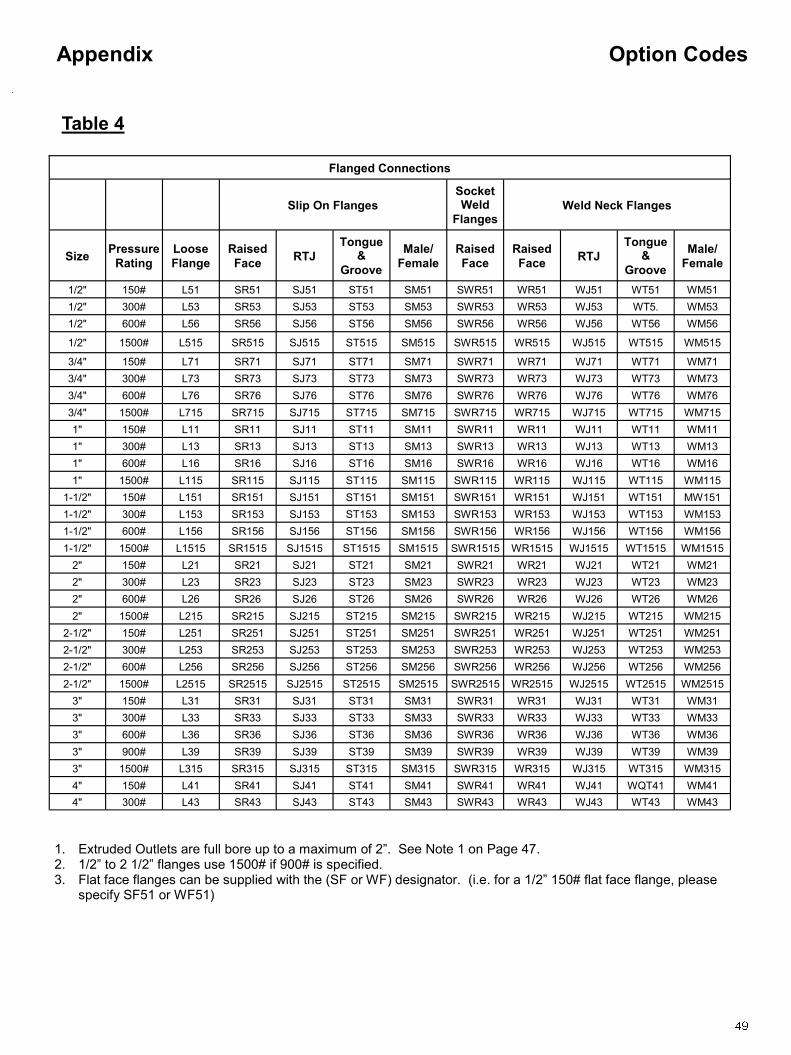
Table 4
Flanged Connections
Slip On Flanges
Socket Weld
Flanges Weld Neck Flanges
Size Pressure
Rating
Loose
Flange
Raised
Face RTJ
Tongue &
Groove
Male/
Female
Raised
Face
Raised
Face RTJ
Tongue &
Groove
Male/
Female
1/2" 150# L51 SR51 SJ51 ST51 SM51 SWR51 WR51 WJ51 WT51 WM51
1/2" 300# L53 SR53 SJ53 ST53 SM53 SWR53 WR53 WJ53 WT5. WM53
1/2" 600# L56 SR56 SJ56 ST56 SM56 SWR56 WR56 WJ56 WT56 WM56
1/2" 1500# L515 SR515 SJ515 ST515 SM515 SWR515 WR515 WJ515 WT515 WM515
3/4" 150# L71 SR71 SJ71 ST71 SM71 SWR71 WR71 WJ71 WT71 WM71
3/4" 300# L73 SR73 SJ73 ST73 SM73 SWR73 WR73 WJ73 WT73 WM73
3/4" 600# L76 SR76 SJ76 ST76 SM76 SWR76 WR76 WJ76 WT76 WM76
3/4" 1500# L715 SR715 SJ715 ST715 SM715 SWR715 WR715 WJ715 WT715 WM715
1" 150# L11 SR11 SJ11 ST11 SM11 SWR11 WR11 WJ11 WT11 WM11
1" 300# L13 SR13 SJ13 ST13 SM13 SWR13 WR13 WJ13 WT13 WM13
1" 600# L16 SR16 SJ16 ST16 SM16 SWR16 WR16 WJ16 WT16 WM16
1" 1500# L115 SR115 SJ115 ST115 SM115 SWR115 WR115 WJ115 WT115 WM115
1-1/2" 150# L151 SR151 SJ151 ST151 SM151 SWR151 WR151 WJ151 WT151 MW151
1-1/2" 300# L153 SR153 SJ153 ST153 SM153 SWR153 WR153 WJ153 WT153 WM153
1-1/2" 600# L156 SR156 SJ156 ST156 SM156 SWR156 WR156 WJ156 WT156 WM156
1-1/2" 1500# L1515 SR1515 SJ1515 ST1515 SM1515 SWR1515 WR1515 WJ1515 WT1515 WM1515
2" 150# L21 SR21 SJ21 ST21 SM21 SWR21 WR21 WJ21 WT21 WM21
2" 300# L23 SR23 SJ23 ST23 SM23 SWR23 WR23 WJ23 WT23 WM23
2" 600# L26 SR26 SJ26 ST26 SM26 SWR26 WR26 WJ26 WT26 WM26
2" 1500# L215 SR215 SJ215 ST215 SM215 SWR215 WR215 WJ215 WT215 WM215
2-1/2" 150# L251 SR251 SJ251 ST251 SM251 SWR251 WR251 WJ251 WT251 WM251
2-1/2" 300# L253 SR253 SJ253 ST253 SM253 SWR253 WR253 WJ253 WT253 WM253
2-1/2" 600# L256 SR256 SJ256 ST256 SM256 SWR256 WR256 WJ256 WT256 WM256
2-1/2" 1500# L2515 SR2515 SJ2515 ST2515 SM2515 SWR2515 WR2515 WJ2515 WT2515 WM2515
3" 150# L31 SR31 SJ31 ST31 SM31 SWR31 WR31 WJ31 WT31 WM31
3" 300# L33 SR33 SJ33 ST33 SM33 SWR33 WR33 WJ33 WT33 WM33
3" 600# L36 SR36 SJ36 ST36 SM36 SWR36 WR36 WJ36 WT36 WM36
3" 900# L39 SR39 SJ39 ST39 SM39 SWR39 WR39 WJ39 WT39 WM39
3" 1500# L315 SR315 SJ315 ST315 SM315 SWR315 WR315 WJ315 WT315 WM315
4" 150# L41 SR41 SJ41 ST41 SM41 SWR41 WR41 WJ41 WQT41 WM41
4" 300# L43 SR43 SJ43 ST43 SM43 SWR43 WR43 WJ43 WT43 WM43
1. Extruded Outlets are full bore up to a maximum of 2‖. See Note 1 on Page 47. 2. 1/2‖ to 2 1/2‖ flanges use 1500# if 900# is specified. 3. Flat face flanges can be supplied with the (SF or WF) designator. (i.e. for a 1/2‖ 150# flat face flange, please
specify SF51 or WF51)

Option Codes Appendix
Table 4 (continued)
Nipples: Sch 40 Std. Plugs:1/2 std. Threaded Couplings: Socket Weld Couplings:
1/2" Sch.40 N54 1/2" P5 1/2" 3000# C53 1/2" 3000# SC53
1/2" Sch.80 N58 3/4" P7 3/4" 3000# C73 3/4" 3000# SC73
1/2" Sch.160 N51 1" P1 1" 3000# C13 1" 3000# SC13
3/4" Sch.40 N74 2" P2
3/4" Sch.80 N78 3" P3
3/4" Sch.160 N71 4" P4
6‖ P6
1" Sch.40 N14
1" Sch.80 N18
1" Sch.160 N11
Screw-On Caps Sock-o-lets Thread -o- lets:
2" 3000# S23 1/2" 3000# S05 1/2" 3000# T053
2-1/2" 3000# S253 3/4" 3000# S07 3/4" 3000# T073
3" 3000# S33 1" 3000# S10 1" 3000# T103
4" 3000# S43 1-1/2" 3000# S15 1-1/2" 3000# T153
2" 3000# S20 2" 3000# T203
1/2" 6000# T056
3/4" 6000# T076
1" 6000# T106
1-1/2" 6000# T156
2" 6000# T206
Hex Head Access Connection Codes
(NPT Top Mount 510/560 series only)
1" 3000# P1 1‖ MNPT
1-1/2‖ 3000# P15 1-1/2‖ MNPT
2" 3000# P2 2‖ MNPT
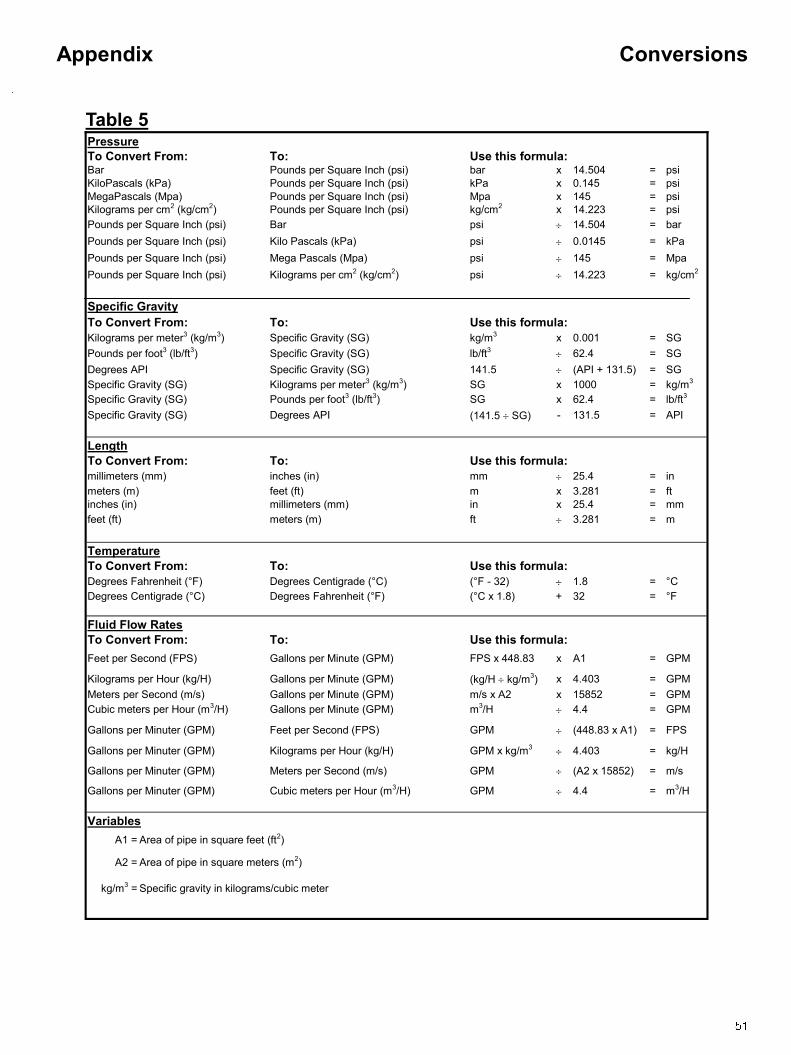
Conversions Appendix
Table 5 Pressure
To Convert From: To: Use this formula: Bar Pounds per Square Inch (psi) bar x 14.504 = psi
KiloPascals (kPa) Pounds per Square Inch (psi) kPa x 0.145 = psi
MegaPascals (Mpa) Pounds per Square Inch (psi) Mpa x 145 = psi
Kilograms per cm2 (kg/cm2) Pounds per Square Inch (psi) kg/cm2 x 14.223 = psi
Pounds per Square Inch (psi) Bar psi 14.504 = bar
Pounds per Square Inch (psi) Kilo Pascals (kPa) psi 0.0145 = kPa
Pounds per Square Inch (psi) Mega Pascals (Mpa) psi 145 = Mpa
Pounds per Square Inch (psi) Kilograms per cm2 (kg/cm2) psi 14.223 = kg/cm2
Specific Gravity
To Convert From: To: Use this formula:
Kilograms per meter3 (kg/m3) Specific Gravity (SG) kg/m3 x 0.001 = SG
Pounds per foot3 (lb/ft3) Specific Gravity (SG) lb/ft3 62.4 = SG
Degrees API Specific Gravity (SG) 141.5 (API + 131.5) = SG
Specific Gravity (SG) Kilograms per meter3 (kg/m3) SG x 1000 = kg/m3
Specific Gravity (SG) Pounds per foot3 (lb/ft3) SG x 62.4 = lb/ft3
Specific Gravity (SG) Degrees API (141.5 SG) - 131.5 = API
Length
To Convert From: To: Use this formula:
millimeters (mm) inches (in) mm 25.4 = in
meters (m) feet (ft) m x 3.281 = ft
inches (in) millimeters (mm) in x 25.4 = mm
feet (ft) meters (m) ft 3.281 = m
Temperature
To Convert From: To: Use this formula:
Degrees Fahrenheit (°F) Degrees Centigrade (°C) (°F - 32) 1.8 = °C
Degrees Centigrade (°C) Degrees Fahrenheit (°F) (°C x 1.8) + 32 = °F
Fluid Flow Rates
To Convert From: To: Use this formula:
Feet per Second (FPS) Gallons per Minute (GPM) FPS x 448.83 x A1 = GPM
Kilograms per Hour (kg/H) Gallons per Minute (GPM) (kg/H kg/m3) x 4.403 = GPM
Meters per Second (m/s) Gallons per Minute (GPM) m/s x A2 x 15852 = GPM
Cubic meters per Hour (m3/H) Gallons per Minute (GPM) m3/H 4.4 = GPM
Gallons per Minuter (GPM) Feet per Second (FPS) GPM (448.83 x A1) = FPS
Gallons per Minuter (GPM) Kilograms per Hour (kg/H) GPM x kg/m3 4.403 = kg/H
Gallons per Minuter (GPM) Meters per Second (m/s) GPM (A2 x 15852) = m/s
Gallons per Minuter (GPM) Cubic meters per Hour (m3/H) GPM 4.4 = m3/H
Variables
A1 = Area of pipe in square feet (ft2)
A2 = Area of pipe in square meters (m2)
kg/m3 = Specific gravity in kilograms/cubic meter