abb totalflow driver - kepware · 2019-12-17 · abbtotalflowdriver tableofcontents...
TRANSCRIPT

ABB Totalflow Driver
© 2019 PTC Inc. All Rights Reserved.

ABB Totalflow Driver
Table of Contents
ABB Totalflow Driver 1
Table of Contents 2
ABB Totalflow Driver 4
Overview 4
Setup 4
Channel Properties — General 5
Channel Properties — Serial Communications 5
Channel Properties —Write Optimizations 8
Channel Properties — Advanced 9
Channel Properties — Communication Serialization 9
Device Properties — General 10
Operating Mode 11
Device Properties — Scan Mode 12
Device Properties — Timing 13
Device Properties — Auto-Demotion 13
Device Properties — Tag Generation 14
Device Properties — Time Synchronization 16
Device Properties — Settings 16
Device Properties — EFM Meters 18
Device Properties — Trend 19
Device Properties — Redundancy 21
Automatic Tag Database Generation 22
Data Types Description 22
Address Descriptions 22
Characteristic Address Descriptions 23
DB2 Protocol Address Descriptions 28
Trend Address Descriptions 29
Statistics Items 31
EFM Pointer Rollback 33
Error Descriptions 34
A communication error occurred while <reading/writing> address <tag address> on device <devicename>: <verbose communication error>. 36
A communication error occurred while reading address <tag address> on device <device name>:Device did not respond. 36
A communication error occurred while reading address <tag address> on device <device name>:General remote NACK error. 36
A communication error occurred while reading address <tag address> on device <device name>:Illegal register read or write. 36
A communication error occurred while reading address <tag address> on device <device name>:Invalid data structure. 37
A communication error occurred while reading address <tag address> on device <device name>:Received data had a CRC error. 37
www.ptc.com
2

ABBTotalflow Driver
A communication error occurred while reading address <tag address> on device <device name>:Transaction ID did not match. 37
A communication error occurred while reading register block <tag address 1 - tag address 2> ondevice <device name>: Invalid VCB Array. 38
Bit index out of range for register address <tag address> on device <device name>. 38
Configuration Invalid XML document: XML Validation Error: '' violates pattern constraint of '[^\s_@."](\s*[^\s@."])*'. The element '{<product_url> /schemas/abb_totalflow}MeterName' with value '<value>'failed to parse. 38
Could not write data for trend file <trend file> on device <device> to disk: <reason>. 38
<Device name> - Failed to read EFM pointer file. <Extended error>. 39
<Device name> - Failed to read trend pointer file. <Extended error>. 39
<Device name> - Failed to write EFM pointer file. <Extended error>. 40
<Device name> - Failed to write trend pointer file. <Extended error>. 40
Device <device name> is not responding. 40
EFM meter <meter name> on device <device name> is invalid. 41
Max. sequence number of 0 reported from device. Aborting <EFM history type> poll. 41
EFM type mismatch for meter <meter name> on device <device name>. The meter is configured for<meter type> in the server but it is a <meter type> meter in the device. 41
Extra data revision not supported. The EFM output file for <meter name> on device <device name>will be missing some data. Extra data revision = <extra data revision>, extra data size = <extra datasize>. 42
Extra data size is 0 bytes. The EFM output file for <meter name> on device <device name> will bemissing some data. Extra data revision = <extra data revision>, extra data size = <extra data size>. 42
Failed to send communication request for address <tag address> on device <device name>. 42
Invalid address for register block <App>.<Array>.<Register X> - <App>.<Array>.<Register Y> ondevice <device name>. 42
Invalid data type <data type> for address <tag address> for device <device name>. 43
Register blocking error, verify that data type <data type> is valid for address <tag address> ondevice <device name>. 43
Serialization of EFM data to temporary file <file name> failed. Reason: <file I/O error>. 43
The rollback value has been adjusted to match the archive size because it exceeded the size of thearchive. | Adjusted rollback = <size>, archive = <name>. 43
Trend file configuration changed for trend file <trend file> on device <device>. Old data moved to<file name>. New data written to <file name>. 44
Trend file <trend file name> does not exist on device <device name>. 44
Trend upload expected new records for trend file <trend file> on device <device name>, but norecords were retrieved. 44
Unable to load TCI Toolkit extradata.ini file, EFM feature may not work properly. 45
Unable to write to <address> on device <device name>. 45
Index 46
www.ptc.com
3
ABB Totalflow Driver
ABB Totalflow DriverHelp version 1.062
CONTENTS
OverviewWhat is the ABB Totalflow Driver?
SetupHow do I configure channels devices for use with this driver?
Data Types DescriptionWhat data types does this driver support?
Address DescriptionsHow do I address a data location on an ABB Totalflow device?
Error DescriptionsWhat error messages are produced by the ABB Totalflow Driver?
OverviewThe ABB Totalflow Driver is designed to work with ABB Totalflow devices that support the native DB1 and DB2Serial Protocols (which are typically used by ABB's flow computers and analyzers). ABB's Totalflow Com-munication Interface (TCI) toolkit is used to implement the application stack for the driver.
EFM functionality is not available in all server versions. To determine whether support is available, refer to the"Server Summary Information" topic located in the server help file.
SetupSupported Device FamiliesThe following device families are supported under the "Totalflow FCU" model:
6000 Series MicroFLO6000 XSeriesG46000 XSeriesG36000 Series FCU
MaximumNumber of Channels and DevicesThis server supports the use of simultaneous multiple communications drivers. Each protocol or driver used in aserver project is called a channel. A server project may consist of many channels with the same com-munications driver or with unique communications drivers. A channel acts as the basic building block of anOPC link.
The maximum number of supported channels is 1024. The maximum number of supported devices per channelis 256.
Ethernet EncapsulationThis driver supports Ethernet Encapsulation, which allows the driver to communicate with serial devicesattached to an Ethernet network using a serial-to-Ethernet terminal server. It also allows the driver to directlycommunicate with a device that is equipped with a TCP/IP port. It may be invoked through the Communicationsgroup in Channel Properties. For more information, refer to the server help file.
www.ptc.com
4

ABBTotalflow Driver
Channel Properties — GeneralThis server supports the use of simultaneous multiple communications drivers. Each protocol or driver used in aserver project is called a channel. A server project may consist of many channels with the same com-munications driver or with unique communications drivers. A channel acts as the basic building block of anOPC link. This group is used to specify general channel properties, such as the identification attributes andoperating mode.
Identification
Name: User-defined identity of this channel. In each server project, each channel name must be unique.Although names can be up to 256 characters, some client applications have a limited display window whenbrowsing the OPC server's tag space. The channel name is part of the OPC browser information. The propertyis required for creating a channel.For information on reserved characters, refer to "How To... Properly Name a Channel, Device, Tag, and Tag
Group" in the server help.
Description: User-defined information about this channel. Many of these properties, including Description, have an associated system tag.
Driver: Selected protocol / driver for this channel. This property specifies the device driver that was selectedduring channel creation. It is a disabled setting in the channel properties. The property is required for creating achannel.
Note: With the server's online full-time operation, these properties can be changed at any time. This includeschanging the channel name to prevent clients from registering data with the server. If a client has alreadyacquired an item from the server before the channel name is changed, the items are unaffected. If, after thechannel name has been changed, the client application releases the item and attempts to re-acquire using theold channel name, the item is not accepted. With this in mind, changes to the properties should not be madeonce a large client application has been developed. Utilize the User Manager to prevent operators from chan-ging properties and restrict access rights to server features.
Diagnostics
Diagnostics Capture: When enabled, this option makes the channel's diagnostic information available to OPCapplications. Because the server's diagnostic features require a minimal amount of overhead processing, it isrecommended that they be utilized when needed and disabled when not. The default is disabled.Note: This property is not available if the driver does not support diagnostics.For more information, refer to "Communication Diagnostics" and "Statistics Tags" in the server help.
Channel Properties — Serial CommunicationsSerial communication properties are available to serial drivers and vary depending on the driver, connectiontype, and options selected. Below is a superset of the possible properties.Click to jump to one of the sections: Connection Type, Serial Port Settings or Ethernet Settings, and Oper-ational Behavior.
Note: With the server's online full-time operation, these properties can be changed at any time. Utilize theUser Manager to restrict access rights to server features, as changes made to these properties can temporarilydisrupt communications.
www.ptc.com
5

ABB Totalflow Driver
Connection Type
Physical Medium: Choose the type of hardware device for data communications. Options include COM Port,None, Modem, and Ethernet Encapsulation. The default is COM Port.
l None: Select None to indicate there is no physical connection, which displays the Operation with noCommunications section.
l COM Port: Select Com Port to display and configure the Serial Port Settings section.l Modem: Select Modem if phone lines are used for communications, which are configured in the
Modem Settings section.l Ethernet Encap.: Select if Ethernet Encapsulation is used for communications, which displays the Eth-
ernet Settings section.l Shared: Verify the connection is correctly identified as sharing the current configuration with anotherchannel. This is a read-only property.
Serial Port Settings
COM ID: Specify the Communications ID to be used when communicating with devices assigned to the chan-nel. The valid range is 1 to 9991 to 16. The default is 1.
Baud Rate: Specify the baud rate to be used to configure the selected communications port.
Data Bits: Specify the number of data bits per data word. Options include 5, 6, 7, or 8.
Parity: Specify the type of parity for the data. Options include Odd, Even, or None.
Stop Bits: Specify the number of stop bits per data word. Options include 1 or 2.
Flow Control: Select how the RTS and DTR control lines are utilized. Flow control is required to communicatewith some serial devices. Options are:
l None: This option does not toggle or assert control lines.l DTR: This option asserts the DTR line when the communications port is opened and remains on.
l RTS: This option specifies that the RTS line is high if bytes are available for transmission. After all buf-fered bytes have been sent, the RTS line is low. This is normally used with RS232/RS485 converterhardware.
l RTS, DTR: This option is a combination of DTR and RTS.
l RTS Always: This option asserts the RTS line when the communication port is opened and remains on.
www.ptc.com
6

ABBTotalflow Driver
l RTS Manual: This option asserts the RTS line based on the timing properties entered for RTS Line Con-trol. It is only available when the driver supports manual RTS line control (or when the properties areshared and at least one of the channels belongs to a driver that provides this support). RTS Manualadds an RTS Line Control property with options as follows:
l Raise: This property specifies the amount of time that the RTS line is raised prior to data trans-mission. The valid range is 0 to 9999 milliseconds. The default is 10 milliseconds.
l Drop: This property specifies the amount of time that the RTS line remains high after data trans-mission. The valid range is 0 to 9999 milliseconds. The default is 10 milliseconds.
l Poll Delay: This property specifies the amount of time that polling for communications isdelayed. The valid range is 0 to 9999. The default is 10 milliseconds.
Tip: When using two-wire RS-485, "echoes" may occur on the communication lines. Since this com-munication does not support echo suppression, it is recommended that echoes be disabled or a RS-485 con-verter be used.
Operational Behavior
l Report Communication Errors: Enable or disable reporting of low-level communications errors.When enabled, low-level errors are posted to the Event Log as they occur. When disabled, these sameerrors are not posted even though normal request failures are. The default is Enable.
l Close Idle Connection: Choose to close the connection when there are no longer any tags being ref-erenced by a client on the channel. The default is Enable.
l Idle Time to Close: Specify the amount of time that the server waits once all tags have been removedbefore closing the COM port. The default is 15 seconds.
Ethernet SettingsNote: Not all serial drivers support Ethernet Encapsulation. If this group does not appear, the functionality is
not supported.
Ethernet Encapsulation provides communication with serial devices connected to terminal servers on the Eth-ernet network. A terminal server is essentially a virtual serial port that converts TCP/IP messages on the Eth-ernet network to serial data. Once the message has been converted, users can connect standard devices thatsupport serial communications to the terminal server. The terminal server's serial port must be properly con-figured to match the requirements of the serial device to which it is attached. For more information, refer to"How To... Use Ethernet Encapsulation" in the server help.
l Network Adapter: Indicate a network adapter to bind for Ethernet devices in this channel. Choose anetwork adapter to bind to or allow the OS to select the default.Specific drivers may display additional Ethernet Encapsulation properties. For more information, refer
to Channel Properties — Ethernet Encapsulation.
Modem Settings
l Modem: Specify the installed modem to be used for communications.
l Connect Timeout: Specify the amount of time to wait for connections to be established before failing aread or write. The default is 60 seconds.
l Modem Properties: Configure the modem hardware. When clicked, it opens vendor-specific modemproperties.
l Auto-Dial: Enables the automatic dialing of entries in the Phonebook. The default is Disable. For moreinformation, refer to "Modem Auto-Dial" in the server help.
l Report Communication Errors: Enable or disable reporting of low-level communications errors.When enabled, low-level errors are posted to the Event Log as they occur. When disabled, these sameerrors are not posted even though normal request failures are. The default is Enable.
www.ptc.com
7

ABB Totalflow Driver
l Close Idle Connection: Choose to close the modem connection when there are no longer any tagsbeing referenced by a client on the channel. The default is Enable.
l Idle Time to Close: Specify the amount of time that the server waits once all tags have been removedbefore closing the modem connection. The default is 15 seconds.
Operation with no Communications
l Read Processing: Select the action to be taken when an explicit device read is requested. Optionsinclude Ignore and Fail. Ignore does nothing; Fail provides the client with an update that indicates fail-ure. The default setting is Ignore.
Channel Properties — Write OptimizationsAs with any server, writing data to the device may be the application's most important aspect. The serverintends to ensure that the data written from the client application gets to the device on time. Given this goal, theserver provides optimization properties that can be used to meet specific needs or improve application respons-iveness.
Write Optimizations
Optimization Method: Controls how write data is passed to the underlying communications driver. Theoptions are:
l Write All Values for All Tags: This option forces the server to attempt to write every value to the con-troller. In this mode, the server continues to gather write requests and add them to the server's internalwrite queue. The server processes the write queue and attempts to empty it by writing data to the deviceas quickly as possible. This mode ensures that everything written from the client applications is sent tothe target device. This mode should be selected if the write operation order or the write item's contentmust uniquely be seen at the target device.
l Write Only Latest Value for Non-Boolean Tags: Many consecutive writes to the same value canaccumulate in the write queue due to the time required to actually send the data to the device. If theserver updates a write value that has already been placed in the write queue, far fewer writes areneeded to reach the same final output value. In this way, no extra writes accumulate in the server'squeue. When the user stops moving the slide switch, the value in the device is at the correct value at vir-tually the same time. As the mode states, any value that is not a Boolean value is updated in the server'sinternal write queue and sent to the device at the next possible opportunity. This can greatly improve theapplication performance.Note: This option does not attempt to optimize writes to Boolean values. It allows users to optimize
the operation of HMI data without causing problems with Boolean operations, such as a momentarypush button.
l Write Only Latest Value for All Tags: This option takes the theory behind the second optimizationmode and applies it to all tags. It is especially useful if the application only needs to send the latestvalue to the device. This mode optimizes all writes by updating the tags currently in the write queuebefore they are sent. This is the default mode.
Duty Cycle: is used to control the ratio of write to read operations. The ratio is always based on one read forevery one to ten writes. The duty cycle is set to ten by default, meaning that ten writes occur for each read oper-ation. Although the application is performing a large number of continuous writes, it must be ensured that readdata is still given time to process. A setting of one results in one read operation for every write operation. If thereare no write operations to perform, reads are processed continuously. This allows optimization for applicationswith continuous writes versus a more balanced back and forth data flow.
www.ptc.com
8

ABBTotalflow Driver
Note: It is recommended that the application be characterized for compatibility with the write optimizationenhancements before being used in a production environment.
Channel Properties — AdvancedThis group is used to specify advanced channel properties. Not all drivers support all properties; so theAdvanced group does not appear for those devices.
Non-Normalized Float Handling: Non-normalized float handling allows users to specify how a driverhandles non-normalized IEEE-754 floating point data. A non-normalized value is defined as Infinity, Not-a-Num-ber (NaN), or as a Denormalized Number. The default is Replace with Zero. Drivers that have native float hand-ling may default to Unmodified. Descriptions of the options are as follows:
l Replace with Zero: This option allows a driver to replace non-normalized IEEE-754 floating point val-ues with zero before being transferred to clients.
l Unmodified: This option allows a driver to transfer IEEE-754 denormalized, normalized, non-number,and infinity values to clients without any conversion or changes.
Note: This property is disabled if the driver does not support floating point values or if it only supports theoption that is displayed. According to the channel's float normalization setting, only real-time driver tags (suchas values and arrays) are subject to float normalization. For example, EFM data is not affected by this setting.lin
For more information on the floating point values, refer to "How To ... Work with Non-Normalized FloatingPoint Values" in the server help.
Inter-Device Delay: Specify the amount of time the communications channel waits to send new requests to thenext device after data is received from the current device on the same channel. Zero (0) disables the delay.
Channel Properties — Communication SerializationThe server's multi-threading architecture allows channels to communicate with devices in parallel. Although thisis efficient, communication can be serialized in cases with physical network restrictions (such as Ethernetradios). Communication serialization limits communication to one channel at a time within a virtual network.
The term "virtual network" describes a collection of channels and associated devices that use the same pipelinefor communications. For example, the pipeline of an Ethernet radio is the master radio. All channels using thesame master radio associate with the same virtual network. Channels are allowed to communicate each in turn,in a "round-robin" manner. By default, a channel can process one transaction before handing communicationsoff to another channel. A transaction can include one or more tags. If the controlling channel contains a devicethat is not responding to a request, the channel cannot release control until the transaction times out. This res-ults in data update delays for the other channels in the virtual network.
Channel-Level Settings
Virtual Network: This property specifies the channel's mode of communication serialization. Options includeNone and Network 1 - Network 500. The default is None. Descriptions of the options are as follows:
www.ptc.com
9

ABB Totalflow Driver
l None: This option disables communication serialization for the channel.l Network 1 - Network 500: This option specifies the virtual network to which the channel isassigned.
Transactions per Cycle: This property specifies the number of single blocked/non-blocked read/write trans-actions that can occur on the channel. When a channel is given the opportunity to communicate, this is the num-ber of transactions attempted. The valid range is 1 to 99. The default is 1.
Global Settings
l Network Mode: This property is used to control how channel communication is delegated. In LoadBalanced mode, each channel is given the opportunity to communicate in turn, one at a time. In Pri-ority mode, channels are given the opportunity to communicate according to the following rules(highest to lowest priority):
l Channels with pending writes have the highest priority.l Channels with pending explicit reads (through internal plug-ins or external client interfaces)are prioritized based on the read's priority.
l Scanned reads and other periodic events (driver specific).
The default is Load Balanced and affects all virtual networks and channels.
Devices that rely on unsolicited responses should not be placed in a virtual network. In situations where com-munications must be serialized, it is recommended that Auto-Demotion be enabled.
Due to differences in the way that drivers read and write data (such as in single, blocked, or non-blocked trans-actions); the application's Transactions per cycle property may need to be adjusted. When doing so, considerthe following factors:
l How many tags must be read from each channel?l How often is data written to each channel?l Is the channel using a serial or Ethernet driver?l Does the driver read tags in separate requests, or are multiple tags read in a block?l Have the device's Timing properties (such as Request timeout and Fail after x successive timeouts)been optimized for the virtual network's communication medium?
Device Properties — GeneralA device represents a single target on a communications channel. If the driver supports multiple controllers,users must enter a device ID for each controller.
Identification
Name: This property specifies the name of the device. It is a logical user-defined name that can be up to 256characters long, and may be used on multiple channels.
www.ptc.com
10
ABBTotalflow Driver
Note: Although descriptive names are generally a good idea, some OPC client applications may have a lim-ited display window when browsing the OPC server's tag space. The device name and channel name becomepart of the browse tree information as well. Within an OPC client, the combination of channel name and devicename would appear as "ChannelName.DeviceName".For more information, refer to "How To... Properly Name a Channel, Device, Tag, and Tag Group" in server
help.
Description: User-defined information about this device.Many of these properties, including Description, have an associated system tag.
Channel Assignment: User-defined name of the channel to which this device currently belongs.
Driver: Selected protocol driver for this device.
Model: This property specifies the specific type of device that is associated with this ID. The contents of thedrop-down menu depends on the type of communications driver being used. Models that are not supported bya driver are disabled. If the communications driver supports multiple device models, the model selection canonly be changed when there are no client applications connected to the device.
Note: If the communication driver supports multiple models, users should try to match the model selection tothe physical device. If the device is not represented in the drop-down menu, select a model that conformsclosest to the target device. Some drivers support a model selection called "Open," which allows users to com-municate without knowing the specific details of the target device. For more information, refer to the driver helpdocumentation.
ID: This property specifies the device's driver-specific station or node. The type of ID entered depends on thecommunications driver being used. For many communication drivers, the ID is a numeric value. Drivers that sup-port a Numeric ID provide users with the option to enter a numeric value whose format can be changed to suitthe needs of the application or the characteristics of the selected communications driver. The format is set bythe driver by default. Options include Decimal, Octal, and Hexadecimal.
Note: If the driver is Ethernet-based or supports an unconventional station or node name, the device'sTCP/IP address may be used as the device ID. TCP/IP addresses consist of four values that are separated byperiods, with each value in the range of 0 to 255. Some device IDs are string based. There may be additionalproperties to configure within the ID field, depending on the driver. For more information, refer to the driver'shelp documentation.
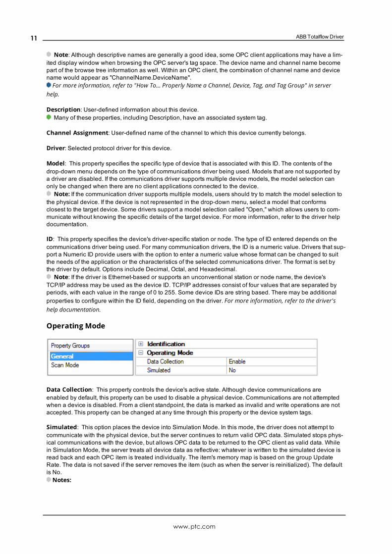
Operating Mode
Data Collection: This property controls the device's active state. Although device communications areenabled by default, this property can be used to disable a physical device. Communications are not attemptedwhen a device is disabled. From a client standpoint, the data is marked as invalid and write operations are notaccepted. This property can be changed at any time through this property or the device system tags.
Simulated: This option places the device into Simulation Mode. In this mode, the driver does not attempt tocommunicate with the physical device, but the server continues to return valid OPC data. Simulated stops phys-ical communications with the device, but allows OPC data to be returned to the OPC client as valid data. Whilein Simulation Mode, the server treats all device data as reflective: whatever is written to the simulated device isread back and each OPC item is treated individually. The item's memory map is based on the group UpdateRate. The data is not saved if the server removes the item (such as when the server is reinitialized). The defaultis No.Notes:
www.ptc.com
11

ABB Totalflow Driver
1. This System tag (_Simulated) is read only and cannot be written to for runtime protection. The Systemtag allows this property to be monitored from the client.
2. In Simulation mode, the item's memory map is based on client update rate(s) (Group Update Rate forOPC clients or Scan Rate for native and DDE interfaces). This means that two clients that reference thesame item with different update rates return different data.
Simulation Mode is for test and simulation purposes only. It should never be used in a production envir-onment.
Device Properties — Scan ModeThe Scan Mode specifies the subscribed-client requested scan rate for tags that require device com-munications. Synchronous and asynchronous device reads and writes are processed as soon as possible; unaf-fected by the Scan Mode properties.
Scan Mode: Specifies how tags in the device are scanned for updates sent to subscribing clients. Descriptionsof the options are:
l Respect Client-Specified Scan Rate: This mode uses the scan rate requested by the client.l Request Data No Faster than Scan Rate: This mode specifies the value set as the maximum scanrate. The valid range is 10 to 99999990 milliseconds. The default is 1000 milliseconds.Note: When the server has an active client and items for the device and the scan rate value is
increased, the changes take effect immediately. When the scan rate value is decreased, the changes donot take effect until all client applications have been disconnected.
l Request All Data at Scan Rate: This mode forces tags to be scanned at the specified rate for sub-scribed clients. The valid range is 10 to 99999990 milliseconds. The default is 1000 milliseconds.
l Do Not Scan, Demand Poll Only: This mode does not periodically poll tags that belong to the devicenor perform a read to get an item's initial value once it becomes active. It is the client's responsibility topoll for updates, either by writing to the _DemandPoll tag or by issuing explicit device reads for indi-vidual items. For more information, refer to "Device Demand Poll" in server help.
l Respect Tag-Specified Scan Rate: This mode forces static tags to be scanned at the rate specified intheir static configuration tag properties. Dynamic tags are scanned at the client-specified scan rate.
Initial Updates from Cache: When enabled, this option allows the server to provide the first updates fornewly activated tag references from stored (cached) data. Cache updates can only be provided when the newitem reference shares the same address, scan rate, data type, client access, and scaling properties. A deviceread is used for the initial update for the first client reference only. The default is disabled; any time a client activ-ates a tag reference the server attempts to read the initial value from the device.
www.ptc.com
12

ABBTotalflow Driver
Device Properties — TimingThe device Timing properties allow the driver's response to error conditions to be tailored to fit the application'sneeds. In many cases, the environment requires changes to these properties for optimum performance. Factorssuch as electrically generated noise, modem delays, and poor physical connections can influence how manyerrors or timeouts a communications driver encounters. Timing properties are specific to each configureddevice.
Communications TimeoutsConnect Timeout: This property (which is used primarily by Ethernet based drivers) controls the amount oftime required to establish a socket connection to a remote device. The device's connection time often takeslonger than normal communications requests to that same device. The valid range is 1 to 30 seconds. Thedefault is typically 3 seconds, but can vary depending on the driver's specific nature. If this setting is not sup-ported by the driver, it is disabled.Note: Due to the nature of UDP connections, the connection timeout setting is not applicable when com-
municating via UDP.
Request Timeout: This property specifies an interval used by all drivers to determine how long the driverwaits for a response from the target device to complete. The valid range is 50 to 9,999,999 milliseconds(167.6667 minutes). The default is usually 1000 milliseconds, but can vary depending on the driver. The defaulttimeout for most serial drivers is based on a baud rate of 9600 baud or better. When using a driver at lowerbaud rates, increase the timeout to compensate for the increased time required to acquire data.
Attempts Before Timeout: This property specifies how many times the driver issues a communicationsrequest before considering the request to have failed and the device to be in error. The valid range is 1 to 10.The default is typically 3, but can vary depending on the driver's specific nature. The number of attempts con-figured for an application depends largely on the communications environment. This property applies to bothconnection attempts and request attempts.
TimingInter-Request Delay: This property specifies how long the driver waits before sending the next request to thetarget device. It overrides the normal polling frequency of tags associated with the device, as well as one-timereads and writes. This delay can be useful when dealing with devices with slow turnaround times and in caseswhere network load is a concern. Configuring a delay for a device affects communications with all other deviceson the channel. It is recommended that users separate any device that requires an inter-request delay to a sep-arate channel if possible. Other communications properties (such as communication serialization) can extendthis delay. The valid range is 0 to 300,000 milliseconds; however, some drivers may limit the maximum valuedue to a function of their particular design. The default is 0, which indicates no delay between requests with thetarget device.
Note: Not all drivers support Inter-Request Delay. This setting does not appear if it is not available.
Device Properties — Auto-DemotionThe Auto-Demotion properties can temporarily place a device off-scan in the event that a device is not respond-ing. By placing a non-responsive device offline for a specific time period, the driver can continue to optimize itscommunications with other devices on the same channel. After the time period has been reached, the driver re-attempts to communicate with the non-responsive device. If the device is responsive, the device is placed on-scan; otherwise, it restarts its off-scan time period.
www.ptc.com
13

ABB Totalflow Driver
Demote on Failure: When enabled, the device is automatically taken off-scan until it is responding again.Tip: Determine when a device is off-scan by monitoring its demoted state using the _AutoDemoted system
tag.
Timeouts to Demote: Specify how many successive cycles of request timeouts and retries occur before thedevice is placed off-scan. The valid range is 1 to 30 successive failures. The default is 3.
Demotion Period: Indicate how long the device should be placed off-scan when the timeouts value isreached. During this period, no read requests are sent to the device and all data associated with the readrequests are set to bad quality. When this period expires, the driver places the device on-scan and allows foranother attempt at communications. The valid range is 100 to 3600000 milliseconds. The default is 10000 mil-liseconds.
Discard Requests when Demoted: Select whether or not write requests should be attempted during the off-scan period. Disable to always send write requests regardless of the demotion period. Enable to discard writes;the server automatically fails any write request received from a client and does not post a message to the EventLog.
Device Properties — Tag GenerationThe automatic tag database generation features make setting up an application a plug-and-play operation.Select communications drivers can be configured to automatically build a list of tags that correspond to device-specific data. These automatically generated tags (which depend on the nature of the supporting driver) can bebrowsed from the clients.
Not all devices and drivers support full automatic tag database generation and not all support the same datatypes. Consult the data types descriptions or the supported data type lists for each driver for specifics.
If the target device supports its own local tag database, the driver reads the device's tag information and usesthe data to generate tags within the server. If the device does not natively support named tags, the driver cre-ates a list of tags based on driver-specific information. An example of these two conditions is as follows:
1. If a data acquisition system supports its own local tag database, the communications driver uses the tagnames found in the device to build the server's tags.
2. If an Ethernet I/O system supports detection of its own available I/O module types, the communicationsdriver automatically generates tags in the server that are based on the types of I/O modules plugged intothe Ethernet I/O rack.
Note: Automatic tag database generation's mode of operation is completely configurable. For more inform-ation, refer to the property descriptions below.
www.ptc.com
14

ABBTotalflow Driver
On Property Change: If the device supports automatic tag generation when certain properties change, the OnProperty Change option is shown. It is set to Yes by default, but it can be set to No to control over when taggeneration is performed. In this case, the Create tags action must be manually invoked to perform tag gen-eration.
On Device Startup: This property specifies when OPC tags are automatically generated. Descriptions of theoptions are as follows:
l Do Not Generate on Startup: This option prevents the driver from adding any OPC tags to the tagspace of the server. This is the default setting.
l Always Generate on Startup: This option causes the driver to evaluate the device for tag information.It also adds tags to the tag space of the server every time the server is launched.
l Generate on First Startup: This option causes the driver to evaluate the target device for tag inform-ation the first time the project is run. It also adds any OPC tags to the server tag space as needed.
Note: When the option to automatically generate OPC tags is selected, any tags that are added to theserver's tag space must be saved with the project. Users can configure the project to automatically savefrom the Tools | Options menu.
On Duplicate Tag: When automatic tag database generation is enabled, the server needs to know what to dowith the tags that it may have previously added or with tags that have been added or modified after the com-munications driver since their original creation. This setting controls how the server handles OPC tags that wereautomatically generated and currently exist in the project. It also prevents automatically generated tags fromaccumulating in the server.
For example, if a user changes the I/O modules in the rack with the server configured to Always Generate onStartup, new tags would be added to the server every time the communications driver detected a new I/O mod-ule. If the old tags were not removed, many unused tags could accumulate in the server's tag space. Theoptions are:
l Delete on Create: This option deletes any tags that were previously added to the tag space before anynew tags are added. This is the default setting.
l Overwrite as Necessary: This option instructs the server to only remove the tags that the com-munications driver is replacing with new tags. Any tags that are not being overwritten remain in theserver's tag space.
l Do not Overwrite: This option prevents the server from removing any tags that were previously gen-erated or already existed in the server. The communications driver can only add tags that are com-pletely new.
l Do not Overwrite, Log Error: This option has the same effect as the prior option, and also posts anerror message to the server's Event Log when a tag overwrite would have occurred.
Note: Removing OPC tags affects tags that have been automatically generated by the communicationsdriver as well as any tags that have been added using names that match generated tags. Users shouldavoid adding tags to the server using names that may match tags that are automatically generated by thedriver.
Parent Group: This property keeps automatically generated tags from mixing with tags that have beenentered manually by specifying a group to be used for automatically generated tags. The name of the groupcan be up to 256 characters. This parent group provides a root branch to which all automatically generated tagsare added.
Allow Automatically Generated Subgroups: This property controls whether the server automatically cre-ates subgroups for the automatically generated tags. This is the default setting. If disabled, the server generatesthe device's tags in a flat list without any grouping. In the server project, the resulting tags are named with theaddress value. For example, the tag names are not retained during the generation process.
Note: If, as the server is generating tags, a tag is assigned the same name as an existing tag, the systemautomatically increments to the next highest number so that the tag name is not duplicated. For example, if thegeneration process creates a tag named "AI22" that already exists, it creates the tag as "AI23" instead.
www.ptc.com
15

ABB Totalflow Driver
Create: Initiates the creation of automatically generated OPC tags. If the device's configuration has been mod-ified, Create tags forces the driver to reevaluate the device for possible tag changes. Its ability to be accessedfrom the System tags allows a client application to initiate tag database creation.
Note: Create tags is disabled if the Configuration edits a project offline.
Device Properties — Time SynchronizationThis group is used to specify the device's time zone and time synchronization properties. It primarily applies totime stamped data or information from battery-powered devices at remote locations where the device time maydeviate (causing issues with the time-stamped data). To prevent this problem from occurring, users can specifythat the server synchronize the device time.
Note: Not all drivers and models support all options.
Time Zone: This property specifies the device's time zone. To ignore the time zone, select one of the first fouroptions in the list (which do not have an offset). The default is the time zone of the local system.
Note: The driver uses this property both when synching the device time and when converting EFMtimestamps from the device to UTC time.
Respect Daylight Saving Time: Select Yes to follow Daylight Saving Time offset when synching the devicetime. Select No to ignore Daylight Saving Time. Only time zones that observe Daylight Saving Time will beaffected. The default is No (disabled).
Note: When enabled, the time of the device is adjusted by +1 hour for Daylight Saving Time (in the spring),and adjusted by -1 hour after Daylight Saving Time (in the fall).
Time Sync Method: This property specifies the method of synchronization. Options include Disabled, Abso-lute, and Interval. The default is Disabled. Descriptions of the options are as follows:
l Disabled: No synchronization.l Absolute: Synchronizes to an absolute time of day specified through the Time property (appears onlywhen Absolute is selected).
l Interval: Synchronizes on startup and every number of minutes specified through the Sync Intervalproperty (appears only when Interval is selected). The default is 60 minutes.
l OnPoll: Synchronizes when poll is completed (applicable only to EFM devices).
Time Sync Threshold: This property specifies the maximum allowable difference, in seconds, between thedevice time and the system time before syncing the device time to the system time. If the threshold is set to 0, atime synchronization occurs every time. The default is 0 seconds. The maximum allowable threshold is 600seconds.
Device Properties — Settings
www.ptc.com
16

ABBTotalflow Driver
Totalflow Settings
l Protocol Version: Specify the protocol version to be used for communications. Options include DB1(not packet-based) and DB2 (packet-based). The default is DB2.Note: DB1 cannot communicate with liquid meters and can only communicate with one meter at a
time. DB2 allows up to 128 meters to be created.l Link Time (s): Specify the interval that the device opens the receive channel. It is used to determinehow many supervisory frames to send so that a remote device's receive channel is on and the request isdetected. Options include 0 seconds, 1 second, 2 seconds, and 4 seconds. The default is 0 seconds.
l Link Time Baud Rate: This property is required for the Link Time calculation when communicatingwith a serial device while Ethernet Encapsulation is enabled. When a COM port is being used, this prop-erty is fixed to the COM port's baud rate. The valid range is 300 to 256,000 bits per second. The defaultis 9600 bits per second.
DB2 and DB1 Settings
l Data Packet Size: Specify the size of each remote packet transmitted using packet control. Optionsinclude 1 KB, 2 KB, 4 KB, 8 KB, 16 KB, and 32 KB. The default is 4 KB. This property affects EFM andtrend uploads only and can be adjusted to optimize communications during uploads.
l Data Block Size: Specify the size of each remote data block transmitted that can be CRC checked.Options include 128 bytes, 256 bytes, 512 bytes, and 1024 bytes. The default is 1024 bytes. This prop-erty affects EFM and trend uploads only and can be adjusted to optimize communications duringuploads.
l EFM Request Limit: This property limits the amount of EFM data that is requested to the specified num-ber of days. Options include 3 days, 10 days, and 35 days. The default is 10 days.
Note: Cached EFM pointer rollback functionality is only supported for the Hourly History, Daily History,and Event archives on DB2 devices. Consult the EFM Exporter help file for more information.
Security CodesUsers can configure security codes in the device to provide communications with additional security. The codesare stored securely.
l Security Code 1: Specify a four digit code that is used for read-only access. It has a maximum length of4 characters. The default is 0000.
l Security Code 2: Specify a four digit code that is used for read/write access. It has a maximum length of4 characters. The default is 0000.
Register Request Blocking
www.ptc.com
17

ABB Totalflow Driver
l Register Block Size: Specify the maximum number of registers that can be read in a single request.The valid range is 1 to 100. The default is 10.
l Register Requests per Packet: Specify the maximum number of register blocks that can be read in asingle packet. The valid range is 1 to 16. The default is 1.
Note: These properties are only available when the selected protocol version is DB2.
Device Properties — EFM MetersEFM Properties
Clear EFM Cache on Next Upload:When this property is enabled any cached EFM data will be cleared fromthe device during the next upload. Pointer files, which are used to track EFM uploads to prevent uploading thesame records twice, will also be removed. All EFM data is re-uploaded. Once the cache is cleared, this propertyis automatically disabled. The default setting is disabled.Note: Changing a meter's order or removing it from the EFM Meter Configuration (see below) causes the
EFM cache to be cleared on the next upload. Although this ensures data integrity, users can avoid it by dis-abling the Clear Cache on Next Upload property before applying any changes.
Meter Count: This property displays the number of meters that have been added to the device.
Meter ConfigurationMeters can be added, removed, and modified under Device | EFM (Meters) in the project tree. The meterorder determines the association with the ABB Totalflow Flow Measurement application. The meter order in theproject tree must coincide with the order of the Flow Applications in ABB's Portable Configuration and Cal-ibration Unit (PCCU) tool. To adjust the meter order, select a meter and use the arrow icons in the toolbaraccordingly.
When creating meters, note that the DB1 protocol supports only a single meter and the DB2 protocol supports amaximum of 128 meters. This does not necessarily reflect the number of meters that can be created in the Total-flow device.
www.ptc.com
18
ABBTotalflow Driver
Notes:
1. Batch record data is not supported.
2. Liquid meters are not compatible with the DB1 protocol.
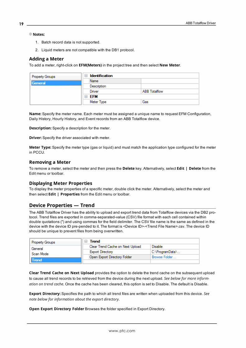
Adding a MeterTo add a meter, right-click on EFM(Meters) in the project tree and then selectNew Meter.
Name: Specify the meter name. Each meter must be assigned a unique name to request EFM Configuration,Daily History, Hourly History, and Event records from an ABB Totalflow device.
Description: Specify a description for the meter.
Driver: Specify the driver associated with meter.
Meter Type: Specify the meter type (gas or liquid) and must match the application type configured for the meterin PCCU.
Removing a MeterTo remove a meter, select the meter and then press the Delete key. Alternatively, select Edit | Delete from theEdit menu or toolbar.
Displaying Meter PropertiesTo display the meter properties of a specific meter, double click the meter. Alternatively, select the meter andthen select Edit | Properties from the Edit menu or toolbar.
Device Properties — TrendThe ABB Totalflow Driver has the ability to upload and export trend data from Totalflow devices via the DB2 pro-tocol. Trend files are exported in comma-separated-value (CSV) file format with each cell contained withindouble quotations (") and using commas for the field delimiter. The CSV file name is the same as defined in thedevice with the device ID pre-pended to it. The format is <Device ID>-<Trend File Name>.csv. The device IDshould be unique to prevent files from being overwritten.
Clear Trend Cache on Next Upload provides the option to delete the trend cache on the subsequent uploadto cause all trend records to be retrieved from the device during the next upload. See below for more inform-ation on trend cache. Once the cache has been cleared, this option is set to Disable. The default is Disable.
Export Directory: Specifies the path to which all trend files are written when uploaded from this device. Seenote below for information about the export directory.
Open Export Directory Folder Browses the folder specified in Export Directory.
www.ptc.com
19
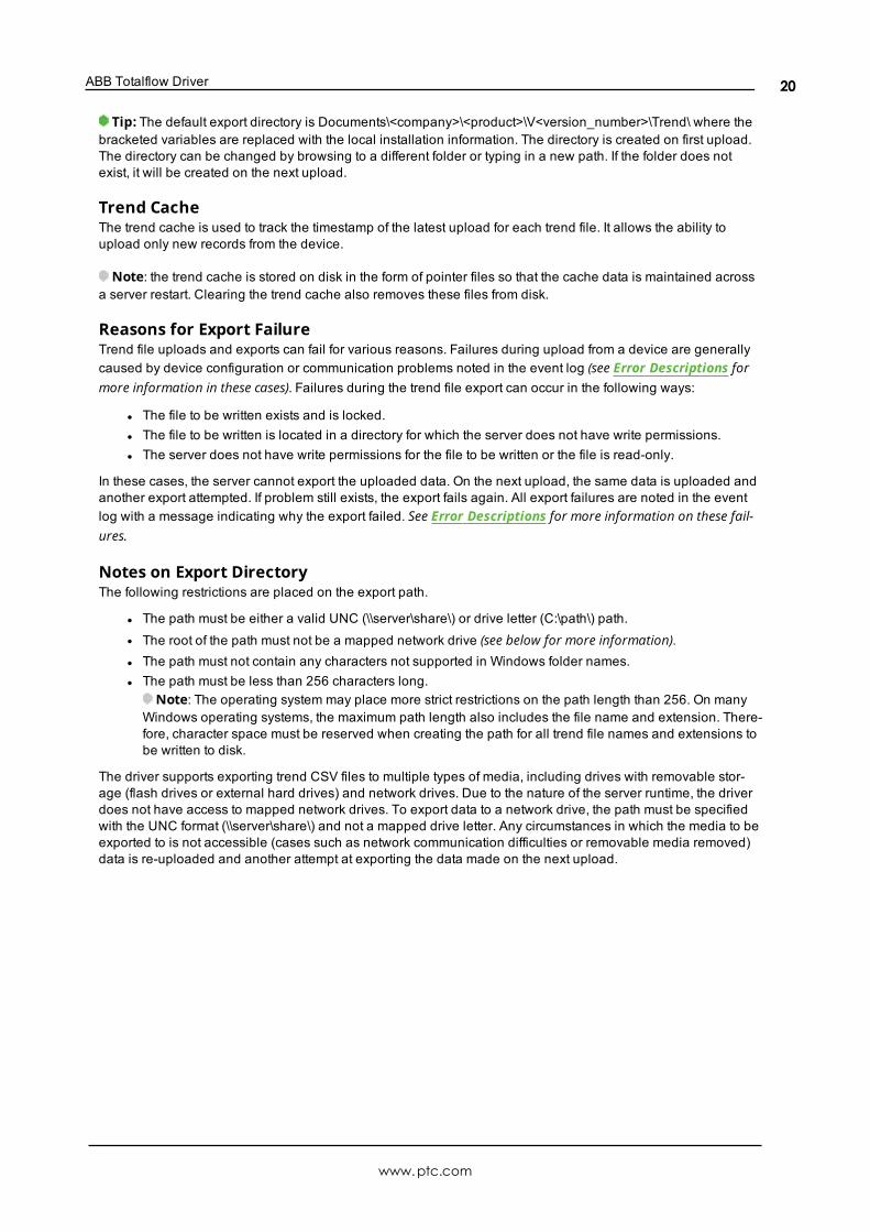
ABB Totalflow Driver
Tip: The default export directory is Documents\<company>\<product>\V<version_number>\Trend\ where thebracketed variables are replaced with the local installation information. The directory is created on first upload.The directory can be changed by browsing to a different folder or typing in a new path. If the folder does notexist, it will be created on the next upload.
Trend CacheThe trend cache is used to track the timestamp of the latest upload for each trend file. It allows the ability toupload only new records from the device.
Note: the trend cache is stored on disk in the form of pointer files so that the cache data is maintained acrossa server restart. Clearing the trend cache also removes these files from disk.
Reasons for Export FailureTrend file uploads and exports can fail for various reasons. Failures during upload from a device are generallycaused by device configuration or communication problems noted in the event log (see Error Descriptions formore information in these cases). Failures during the trend file export can occur in the following ways:
l The file to be written exists and is locked.l The file to be written is located in a directory for which the server does not have write permissions.l The server does not have write permissions for the file to be written or the file is read-only.
In these cases, the server cannot export the uploaded data. On the next upload, the same data is uploaded andanother export attempted. If problem still exists, the export fails again. All export failures are noted in the eventlog with a message indicating why the export failed. See Error Descriptions for more information on these fail-ures.
Notes on Export DirectoryThe following restrictions are placed on the export path.
l The path must be either a valid UNC (\\server\share\) or drive letter (C:\path\) path.l The root of the path must not be a mapped network drive (see below for more information).l The path must not contain any characters not supported in Windows folder names.l The path must be less than 256 characters long.
Note: The operating system may place more strict restrictions on the path length than 256. On manyWindows operating systems, the maximum path length also includes the file name and extension. There-fore, character space must be reserved when creating the path for all trend file names and extensions tobe written to disk.
The driver supports exporting trend CSV files to multiple types of media, including drives with removable stor-age (flash drives or external hard drives) and network drives. Due to the nature of the server runtime, the driverdoes not have access to mapped network drives. To export data to a network drive, the path must be specifiedwith the UNC format (\\server\share\) and not a mapped drive letter. Any circumstances in which the media to beexported to is not accessible (cases such as network communication difficulties or removable media removed)data is re-uploaded and another attempt at exporting the data made on the next upload.
www.ptc.com
20

ABBTotalflow Driver
Device Properties — Redundancy
Redundancy is available with the Media-Level Redundancy Plug-In.Consult the website, a sales representative, or the user manual for more information.
www.ptc.com
21

ABB Totalflow Driver
Automatic Tag Database GenerationThe ABB Totalflow Driver can be configured to automatically generate tags for characteristic items and trendfiles in the device, as well as tags that indicate the status of a trend upload.
The Characteristic Items, created when the protocol version is configured for DB1, are described by three func-tional groups: Last Volume Period (LVP) Tags, Current Measurement Tags, and Device Setup Tags. All tagsare read only. These tags are created in the Device Setup and Measurement groups.
Tags related to trend file uploads are created in a tag group at the device level named “Trend”. The trend fileupload tags created include one tag per file defined in the device, as well TF_UploadAll and TF_LastModifiedtags. Trend status are also generated: TS_UploadingTrend, TS_UploadingTrendFile, and TS_Error (see AddressDescriptions for more information on these tags).
To generate tags from the device:
1. In the Configuration, select the device for which to generate tags.
2. Right-click and select Properties... to open the Device Properties.
3. Select the Tag Generation group.
4. Click the Create tags button to initiate tag database creation.
5. Click the Close button to exit the grid view.
6. In the Event Log, verify messages confirming successful generation.
Note: An automatic tag generation creates the characteristic items regardless of the server’s ability to con-nect to the device. If the server is not connected to the device or communications are lost during the tag gen-eration, the trend file tags are not created and a warning message is posted in the event log.
For more information about automatic tag generation properties, see the server help file.
See Also:Address DescriptionsCharacteristic Address DescriptionsTrend Address DescriptionsDB1 and DB2 Settings
Data Types Description
Data Type DescriptionBool Single bitChar Signed 8-bit valueByte Unsigned 8-bit valueShort Signed 16-bit valueWord Unsigned 16-bit valueLong Signed 32-bit valueDWord Unsigned 32-bit valueFloat 32-bit floating point valueString Null-terminated character array
Address DescriptionsABB Totalflow devices organize data by application, array, and register. Although the meaning and type of datais specific to the application type, a fully-qualified ABB Totalflow address requires all three of these parameters.Its syntax is as follows: <application #>.<array #>.<register #>.
www.ptc.com
22

ABBTotalflow Driver
Each application is usually designed to perform a specific task, calculation, or function in the ABB Totalflowdevice. The application numbers are not standardized, meaning that the application number for a Flow Meas-urement application AGA3-1 can differ from device-to-device. The application numbers are based on the applic-ation category and the order in which they are added to the device. The ABB Totalflow Driver follows thisaddressing convention, supporting the following syntax:
<Application>.<Array>.<Register>/<bit><Application>.<Array>.<Register>[row][column]
Note: The valid range for the register identifier fields are 0-255, 0-255, and 0-65535 respectively. The bitindex is validated against the specified OPC type. In the event that the register type does not support the spe-cified bit index, the read fails and an appropriate error message is logged once per tag. The product of rowsmultiplied by columns cannot exceed the maximum register block size of 100. A 1-length row/column isallowed.
For more information, select a link from the list below.Characteristic Address DescriptionsDB2 Protocol Address DescriptionsTrend Address DescriptionsStatistics Items
Characteristic Address DescriptionsData BlockingG1 and G2 devices do not use registers. Data can be requested from a number of categories: the processing isthe same for all of them. Data is requested in two blocks based on the method of data request. Characteristicsitems cannot be requested individually. The driver supports the Current Measurement and/or Device Setup tagcategories. Due to blocking limitations, it is recommended that data be retrieved by register for DB2 devices.Only the Characteristic Address Tags are available for DB1 devices (because they do not use a register-basedarchitecture). For more information, refer to DB2 Protocol Address Descriptions.
The Characteristic Items are described by three functional groups: Last Volume Period (LVP) Tags, CurrentMeasurement Tags, and Device Setup Tags. All tags are read only.
Last Volume Period (LVP) TagsABB Totalflow devices calculate volume in a user-configurable interval between 1 and 60 minutes.
Address Data Type DescriptionLVPALARMS Byte AlarmsLVPACF Float Accumulated FlowLVPDP Float DPLVPAP Float APLVPTF Float TemperatureLVPVOLUME Float VolumeLVPQV Float QvLVPIRANGE Float Turbine RangeLVPICOUNTS Float Turbine CountsLVPEXT Float ExtensionLVPCP Float CpLVPFB Float FbYSTACFLOW Float Yesterday's Low ACFLVPFR Float F(r)
www.ptc.com
23
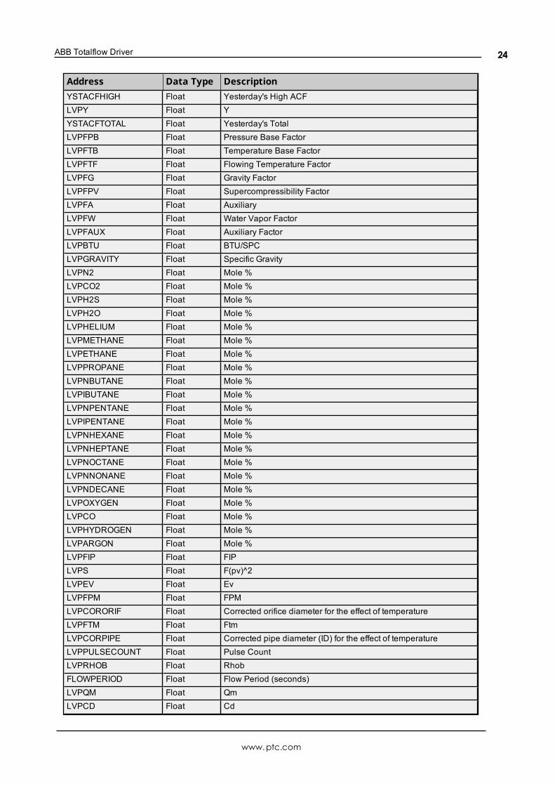
ABB Totalflow Driver
Address Data Type DescriptionYSTACFHIGH Float Yesterday's High ACFLVPY Float YYSTACFTOTAL Float Yesterday's TotalLVPFPB Float Pressure Base FactorLVPFTB Float Temperature Base FactorLVPFTF Float Flowing Temperature FactorLVPFG Float Gravity FactorLVPFPV Float Supercompressibility FactorLVPFA Float AuxiliaryLVPFW Float Water Vapor FactorLVPFAUX Float Auxiliary FactorLVPBTU Float BTU/SPCLVPGRAVITY Float Specific GravityLVPN2 Float Mole %LVPCO2 Float Mole %LVPH2S Float Mole %LVPH2O Float Mole %LVPHELIUM Float Mole %LVPMETHANE Float Mole %LVPETHANE Float Mole %LVPPROPANE Float Mole %LVPNBUTANE Float Mole %LVPIBUTANE Float Mole %LVPNPENTANE Float Mole %LVPIPENTANE Float Mole %LVPNHEXANE Float Mole %LVPNHEPTANE Float Mole %LVPNOCTANE Float Mole %LVPNNONANE Float Mole %LVPNDECANE Float Mole %LVPOXYGEN Float Mole %LVPCO Float Mole %LVPHYDROGEN Float Mole %LVPARGON Float Mole %LVPFIP Float FIPLVPS Float F(pv)^2LVPEV Float EvLVPFPM Float FPMLVPCORORIF Float Corrected orifice diameter for the effect of temperatureLVPFTM Float FtmLVPCORPIPE Float Corrected pipe diameter (ID) for the effect of temperatureLVPPULSECOUNT Float Pulse CountLVPRHOB Float RhobFLOWPERIOD Float Flow Period (seconds)LVPQM Float QmLVPCD Float Cd
www.ptc.com
24

ABBTotalflow Driver
Current Measurement TagsAddress Data Type DescriptionCURACCVOL Float Current Accumulated VolumeCURACCVOLTURBINE Float Current Accumulated Volume (Turbine)CURAP Float Current Static PressureCURDP Float Current Differential PressureCURMACF Float Current Actual MCFCURTF Float Current TemperatureCURFLOW Float Current Flow Rate (SCF)CURVOLTAGE Float Current VoltageYSTACCVOL Float Yesterday's Accumulated VolumeYSTMCFTOTAL Float Yesterday's Total MCF
Device Setup Tags
AddressDataType
Description
CONTRACTHOUR Byte Contract Hour (0-23)
STREAMID Uint32
4 Bytes. In ASCII, the Stream ID is iiii-aa-ss.
Bytes 0 & 1: AIU number (iiii); 0000 to 9999, with the bytes reversed fromMicrosoftByte 2: Analyzer number (aa); 1-32Byte 3: Stream number in the analyzer (ss); 1-32
FIXEDAXONERR Bool
If STREAMATTACHED is 1 and the received analysis is not correct or, ifno analysis is received, then:
False = Use last known good analysisTrue = Use fixed analysis
STREAMATTACHED Bool False = Always use fixed analysisTrue = Attached to AIU
RTDINSTALLED Bool False = NoTrue = Yes
USEMEASTEMP Bool False = Fixed TempTrue = Live
CHECKSEC Bool Use Security
MONELORIF Bool False = StainlessTrue = Monel
USEFB Bool Use FB in CalculationsUSES Bool Use S (F(pv)^2); Turbine OnlyUSEFR Bool Use Flow RateUSEFTC Bool Use Temperature Correction FactorUSEY Bool Use Expansion FactorUSEFPC Bool Use Pressure Correction FactorUSEFTB Bool Use Temperature Base FactorUSEFPB Bool Use Pressure Base FactorUSEFTF Bool Use Flowing Temperature FactorUSEFG Bool Use Gravity FactorUSEFPV Bool Use Super Compressibility Factor
www.ptc.com
25

ABB Totalflow Driver
AddressDataType
Description
USEFA Bool AuxiliaryLCCONTACT Bool Charger LowDPLOWCONTACT Bool DP Low ContactDPHICONTACT Bool DP High ContactAPLOWCONTACT Bool AP Low ContactAPHICONTACT Bool AP High ContactREMSENSECONTAC Bool Use Remote SenseAUTORESET Bool Automatic ResetVOLSPCONTACT Bool Use Volume Set PointUSEFW Bool Use Water Vapor FactorUSEFAUX Bool Use Auxiliary FactoryFIXEDAP Float Fixed APUSEMEASAP Float Use Measured APFB Float Basic Orifice FactorORIFICE Float Orifice Diameter (inches)PIPE Float Pipe Diameter (inches)GRAVITY Float Specific GravityDPLOWLIM Float DP Low LimitDPHILIM Float DP High LimitAPLOWLIM Float AP Low LimitAPHILIM Float AP High LimitCO2 Float Mole % CO2N2 Float Mole % N2APLOWCAL Float AP Calibration: Low PointAPMIDCAL Float AP Calibration: Mid PointAPHICAL Float AP Calibration: High PointDPLOWCAL Float DP Calibration: Low PointDPMIDCAL Float DP Calibration: Mid PointDPHICAL Float DP Calibration: High PointZEROCUTOFF Float DP Zero CutoffTBASE Float Temperature BasePBASE Float Pressure BaseFIXEDTF Float Fixed TemperatureTEMPBIAS Float Temperature BiasVISC Float CentiposeRSPH Float Ratio of Specific HeatsFT Float Mass Flow Calibration Temperature CoefficientFP Float PressureBTU Float BTU/SCFACFLOWLIM Float Turbine: Low LimitACFHILIM Float Turbine: High LimitFAUX Float Auxiliary FactoryK Float Turbine
CALCUNITS ByteBit Definitions
www.ptc.com
26

ABBTotalflow Driver
AddressDataType
Description
0 = US Units1 = IP Units2 = MT Units3 = SI Units
ACFLOWLIM Float Accumulated Flow Limit
ZMETHOD Float
Bit Definition
0 = NX19, fixed Ft, Fp1 = NX19 GCN or GCNM2 = NX19 GCN3 = NX19 GCNM7 = AGA-8 HGCN8 = AGA-8 GCN Limited Number of High Pressure FCUs10= AGA-8 GCNM11= AGA-8 Gross 1992 (Gross 2)12= AGA-8 Detail 1992
TAPLOCATION Bool 0 = Downstream1 = Upstream
TAPTYPE Bool 0 = Flange1 = Pipe
VOLCALCMETHOD Byte
Value Definition
0= No Volume Calculation1 = AGA-3 19852= AGA-3 1992, API 14.3
FIXEDCD Bool 0 = Fixed1 = Calculated CD
PIPEREFTEMP Float Reference Temperature (F)ORIFREFTEMP Float Orifice Temperature (F)ZBA Float Z of Air at Base ConditionsVOLCALCPER Uint16 Volume Calculation Period in SecondsVOLLOGPER Uint32 Volume Log Period in SecondsH2S Float Mole %H2O Float Mole %HELIUM Float Mole %METHANE Float Mole %ETHANE Float Mole %PROPANE Float Mole %NBUTANE Float Mole %IBUTANE Float Mole %NPENTANE Float Mole %IPENTANE Float Mole %NHEXANE Float Mole %NHEPTANE Float Mole %NOCTANE Float Mole %NNONANE Float Mole %NDECANE Float Mole %OXYGEN Float Mole %CO Float Mole %
www.ptc.com
27

ABB Totalflow Driver
AddressDataType
Description
ORIFEXP Float Orifice Plate Coefficient of ExpansionPIPEEXP Float Pipe Coefficient of ExpansionBAROP Float Barometric PressureUSECALCCD Bool Use Calculated CdHYDROGEN Float Mole %ARGON Float Mole %APMIDLOWCAL Float AP Calibration: Mid-LowAPMIDHICAL Float AP Calibration: Mid-HighDPMIDLOWCAL Float DP Calibration: Mid-LowDPMIDHICAL Float DP Calibration: Mid-HighSQRTAVG Float Square Root MeanVOLSP Float Volume Set PointTFLOWLIM Float Temperature Low LimitTFHILIM Float Temperature High LimitFLOWLOWLIM Float Flow Low LimitFLOWHILIM Float Flow High Limit
PASSWORDMODE Bool 0 = No Password Mode1 = Mode Enabled
FIRSTAX Bool At Least One Good Analyzer
PRIMARYELEM Byte 0= Orifice1= Turbine
REPORTUNITS Byte
Report Unite
Bit Definition:0 = US1 = IP2 = MT3 = SI
DB2 Protocol Address DescriptionsDB2 Protocol addressing information applies to G2, G3, and G4 devices.
Data BlockingDue to blocking limitations, it is recommended that data be retrieved by register for DB2 device. A DB2 registerrequest consists of a base address (in the form of <application>.<array>.<register>) and a register count. Theregisters retrieved in a request are always in the same Totalflow array and have the same data type. Forexample, if 10 registers are requested beginning at "9.3.0," the response contains data for "9.3.0" through"9.3.9" with a uniform data type. The driver blocks data in the same manner.
Register data is retrieved from the TCI toolkit as an array of bytes. The data type is inferred from the size of thearray and the number of elements that were requested. The element size within a data block is fixed based onthe largest atomic type (because the data type cannot be accurately deduced until data is retrieved from thedevice). Encoding the data length provides greater flexibility for the client tag data type. This means that usersdo not need to know the Totalflow data type when defining client tags in the driver. Data type mismatches resultin truncation. There is no special handling for floating point values. Examples are as follows:
1. A Word tag is defined with an address of "9.3.0". The ABB Totalflow device has this register defined asan int32. The driver reads the tag and sets its quality to Bad because a Word cannot properly representall int32 values. An error message is posted to the Event Log.
www.ptc.com
28

ABBTotalflow Driver
2. A DWord tag is defined with an address of "9.5.0". The ABB Totalflow device has this register defined asa Float. The driver reads the tag, receives the value "1.523," and stores it in the block memory. When thetag is updated, its value is 1069740458 (the binary equivalent of 1.523).
Strings are not blocked by the driver due to their fixed size. A runtime error (including an Event Log message) isposted when a string register is assigned a blockable type. Strings are not converted to any other data type. Fur-thermore, multiple register requests can be included in a single DB2 transaction. This means that the driver canservice multiple block tag reads with a single device request/response. The number of register requests perpacket is user-configurable. The driver pools tags based on the following criteria:
l All tags will be read or write.l All tags must be for the same device.l The number of tags is limited to the number specified by the user.
Bit-within-Word BooleansBit-within-Word Booleans provide a mechanism for interpreting register data as a bit field. For reads, thisinvolves using a mask to determine the Boolean value for a desired bit (which is specified in the tag's address).In order to write bit values, the driver must perform a Read/Modify/Write operation to ensure that only a singlebit is being set.
Trend Address DescriptionsTrend tags apply to all ABB Totalflow devices that support the DB2 protocol and trend logging.
Trend File TagsSyntax Example: Channel.Device.TF_UploadAll
TagDataType
Description Access
TF_<trend_file_name> Boolean
This tag is used to upload a single file specified by <trend_file_name> where trend_file_name must match the name of a trendfile defined in the device. Writing any value to this tag initiates anupload. This tag always reads 0.
Write Only
TF_LastModified Boolean
This tag is used to upload the trend file that was last modified inthe device. This tag reserves the name LastModified; thereforetrend files should not be created on the device with this name.Writing any value to this tag initiates an upload. This tag alwaysreads 0.
Write Only
TF_UploadAll Boolean
This tag is used to upload all trend files on the device. This tagreserves the name UploadAll; therefore trend files should not becreated on the device with this name. Writing any value to thistag initiates an upload. This tag always reads 0.
Write Only
TF_UploadLastHours Word
This tag is defines how many hours of records, from the currenttime, will be uploaded. It only specifies the number of hours anddoes not initiate the upload. The value is used only for the nextupload initiated by a single trend file tag, last modified tag, orupload all tag and returns to zero when the upload is complete.This tag reserves the name UploadLastHours; therefore trendfiles should not be created on the device with this name.
Notes:
l The clear cache property has no effect on uploads thatuse this tag. Upon completion of an upload that usesthis tag, the trend cache is updated with the timestampof the newest record uploaded.
l If an existing CSV file isn’t consumed before using thistag, the file could be missing data or have duplicatedata.
Read/Write
www.ptc.com
29

ABB Totalflow Driver
TagDataType
Description Access
l This tag uses the time zone/DST properties in the TimeSynchronization group in the Device Properties. Theseproperties must match the device’s time zone/DST set-tings for this tag to work properly.
Trend File Tag Validation Requirements:The following address requirements must be met when creating trend file tags:
l Length (including the “TF_”) must be at least four (4) characters.l Length (including the “TF_”) must be less than 66 characters. This is due to the 63 character restrictionenforced by the TCI toolkit.
l The address must be valid ASCII characters.l The file name should not contain white space other than the standard space character.l Prohibited characters are double quotes (") and ‘at’ symbol (@).
Notes:
l The file’s Scan Status in the device must be set to “On” to upload the trend file from the device.l These addresses are not case sensitive.
Trend Status TagsSyntax Example: Channel.Device.TS_Uploading
TagDataType
Description Access
TS_Uploading BooleanThis tag indicates whether the driver is currently retrievinga trend file from the device and exporting trend data todisk.
Read Only
TS_UploadingFile String This tag indicates the name of the trend file that the driveris currently uploading from the device. Read Only
TS_ErrorOnLastUpload Boolean
This tag indicates that an error has occurred during themost recent trend file upload. If an error occurs during asingle file or upload all request, this tag is set to TRUE.The tag is reset upon completion of the next successfulupload, including uploads that result in no new data.
Read Only
TS_LastUploadStart Date
This tag indicates the time that the most recent trend fileupload began. All times are reported in local time. If noupload has started, the tag reports 01/01/160100:00:00.000.
Read Only
TS_LastUploadEnd Date
This tag indicates the time that the most recent trend fileupload finished. All times are reported in local time. If noupload has completed, the tag reports 01/01/160100:00:00.000.
Read Only
TS_LastUp-loadDurationSec Double
This tag indicates the amount of time (in seconds) the lasttrend file upload took to complete. This tag is updated onupload completion whether the upload succeeds or fails.
Read Only
TS_ErrorCount DWordThis tag increments every time a trend file upload fails dueto a communication or export error. Writing any value tothis tag resets the counter to zero.
Read/Write
Blocking Trend File Uploads
www.ptc.com
30

ABBTotalflow Driver
When possible, trend files are uploaded in multiple small blocks of records instead of one large block to optim-ize data throughput over noisy communication links. The Totalflow firmware provides the information requiredto block uploads for up to 15 trend files via registers (see Notes below). If there are more than 15 trend files con-figured on a device, some of the trend file uploads will not be uploaded in small blocks. One exception is that alltrend file uploads initiated with a non-zero TF_UploadLastHours value are blocked regardless of the number oftrend files configured on the device.
Notes:
l The driver records the timestamp of the newest record in the file at the beginning of a trend file upload.If records are being logged at a high rate and the file has wrapped, it is possible that the driver mayupload a few records less than the full trend file size when uploading from a cleared cache state. Thisis expected behavior as the driver will upload those records on the next upload.
l The following register addresses are used when determining if a trend file upload can be blocked. If atrend file’s name is in one of these 15 registers when an upload for the file is initiated, the file’s uploadis blocked. If the trend file’s “Scan Status” is set to “Off” in the device, the trend file’s name will notappear in these registers.
<trend app num>.241.0 through <trend app num>.241.14
where <trend app num> is the application slot number where the trend system application is instan-tiated.
Statistics ItemsStatistical items use data collected through additional diagnostics information, which is not collected by default.To use statistical items, Communication Diagnostics must be enabled. To enable Communication Diagnostics,right-click on the channel in the Project View and click Properties | Enable Diagnostics. Alternatively,double-click on the channel and select Enable Diagnostics.
Channel-Level Statistics ItemsThe syntax for channel-level statistics items is <channel>._Statistics.
Note: Statistics at the channel level are the sum of those same items at the device level.
ItemDataType
Access Description
_CommFailures DWord Read/Write The total number of times communication has failed (or has runout of retries).
_ErrorResponses DWord Read/Write The total number of valid error responses received._Expec-tedResponses DWord Read/Write The total number of expected responses received.
_LastResponseTime String Read Only The time at which the last valid response was received.
_LateData DWord Read/Write
The total number of times that a tag is read later than expected(based on the specified scan rate). This value does notincrease due to a DNR error state. A tag is not counted as late(even if it was) on the initial read after a communications loss.This is by design.
_MsgResent DWord Read/Write The total number of messages sent as a retry._MsgSent DWord Read/Write The total number of messages sent initially.
_MsgTotal DWord Read Only The total number of messages sent (both _MsgSent + _MsgResent).
_PercentReturn Float Read Only The proportion of expected responses (Received) to initialsends (Sent) as a percentage.
_PercentValid Float Read Only The proportion of total valid responses received (_TotalRe-
www.ptc.com
31

ABB Totalflow Driver
ItemDataType
Access Description
sponses) to total requests sent (_MsgTotal) as a percentage.
_Reset Bool Read/Write Resets all diagnostic counters. Writing to the _Reset Tagcauses all diagnostic counters to be reset at this level.
_RespBadCheck-sum DWord Read/Write The total number of responses with checksum errors.
_RespTimeouts DWord Read/Write The total number of messages that failed to receive any kind ofresponse.
_RespTruncated DWord Read/Write The total number of messages that received only a partialresponse.
_TotalResponses DWord Read Only The total number of valid responses received (_ErrorRe-sponses + _ExpectedResponses).
Statistical items are not updated in simulation mode (see device general properties).
Device-Level Statistics ItemsThe syntax for device-level statistics items is <channel>.<device>._Statistics.
ItemDataType
Access Description
_CommFailures DWord Read/Write The total number of times communication has failed (or has runout of retries).
_ErrorResponses DWord Read/Write The total number of valid error responses received._Expec-tedResponses DWord Read/Write The total number of expected responses received.
_LastResponseTime String Read Only The time at which the last valid response was received.
_LateData DWord Read/Write
The total number of times that a tag is read later than expected(based on the specified scan rate). This value does notincrease due to a DNR error state. A tag is not counted as late(even if it was) on the initial read after a communications loss.This is by design.
_MsgResent DWord Read/Write The total number of messages sent as a retry._MsgSent DWord Read/Write The total number of messages sent initially.
_MsgTotal DWord Read Only The total number of messages sent (both _MsgSent + _MsgResent).
_PercentReturn Float Read Only The proportion of expected responses (Received) to initialsends (Sent) as a percentage.
_PercentValid Float Read Only The proportion of total valid responses received (_TotalRe-sponses) to total requests sent (_MsgTotal) as a percentage.
_Reset Bool Read/Write Resets all diagnostic counters. Writing to the _Reset Tagcauses all diagnostic counters to be reset at this level.
_RespBadCheck-sum DWord Read/Write The total number of responses with checksum errors.
_RespTimeouts DWord Read/Write The total number of messages that failed to receive any kind ofresponse.
_RespTruncated DWord Read/Write The total number of messages that received only a partialresponse.
_TotalResponses DWord Read Only The total number of valid responses received (_ErrorRe-sponses + _ExpectedResponses).
Statistical items are not updated in simulation mode (see device general properties).
www.ptc.com
32

ABBTotalflow Driver
EFM Pointer RollbackThis driver supports EFM Pointer rollback, which allows the user to manually change the EFM pointer value toan earlier position in the archive using system tags provided by the EFM Exporter.
For more information, refer to the EFM Exporter Help file.
www.ptc.com
33

ABB Totalflow Driver
Error DescriptionsThe following messages may be generated. Click on the link for a description of the message.
Communication Error MessagesA communication error occurred while <reading/writing> address <tag address> ondevice <device name>: <verbose communication error>.A communication error occurred while reading address <tag address> on device <devicename>: Device did not respond.A communication error occurred while reading address <tag address> on device <devicename>: General remote NACK error.A communication error occurred while reading address <tag address> on device <devicename>: Illegal register read or write.A communication error occurred while reading address <tag address> on device <devicename>: Invalid data structure.A communication error occurred while reading address <tag address> on device <devicename>: Received data had a CRC error.A communication error occurred while reading address <tag address> on device <devicename>: Transaction ID did not match.A communication error occurred while reading register block <tag address 1 - tag address2> on device <device name>: Invalid VCB Array.
Device-Specific Error MessagesBit index out of range for register address <tag address> on device <device name>.Could not write data for trend file <trend file> on device <device> to disk. <reason>.<Device name> - Failed to read EFM pointer file. <Extended error>.<Device name> - Failed to write EFM pointer file. <Extended error>.<Device name> - Failed to read trend pointer file. <Extended error>.<Device name> - Failed to write trend pointer file. <Extended error>.Device <device name> is not responding.EFM type mismatch for meter <meter name> on device <device name>. The meter is con-figured for <meter type> in the server but it is a <meter type> meter in the device.Max. sequence number of 0 reported from device. Aborting <EFM history type> poll.Extra data revision not supported. The EFM output file for <meter name> on device<device name> will be missing some data. Extra data revision = <extra data revision>,extra data size = <extra data size>.Extra data size is 0 bytes. The EFM output file for <meter name> on device <devicename> will be missing some data. Extra data revision = <extra data revision>, extra datasize = <extra data size>.Failed to send communication request for address <tag address> on device <devicename>.Invalid address for register block <App>.<Array>.<Register X> - <App>.<Array>.<RegisterY> on device <device name>.Invalid data type <data type> for address <tag address> for device <device name>Register blocking error, verify that data type <data type> is valid for address <tagaddress> on device <device name>.
www.ptc.com
34

ABBTotalflow Driver
Serialization of EFM data to temporary file <file name> failed. Reason: <file I/O error>.The rollback value has been adjusted to match the archive size because it exceeded thesize of the archive.Trend file configuration changed for trend file <trend file> on device <device>. Old datamoved to <file name>. New data written to <file name>.Trend file <trend file name> does not exist on device <device name>.Trend upload expected new records for trend file <trend file> on device <device name>,but no records were retrieved.Unable to load TCI Toolkit extradata.ini file, EFM feature may not work properly.Unable to write to <address> on device <device name>.
www.ptc.com
35

ABB Totalflow Driver
A communication error occurred while <reading/writing> address <tagaddress> on device <device name>: <verbose communication error>.Error Type:Warning
Possible Cause:There was an error in communications.
Solution:
1. For more information, refer to the verbose error message.
2. Verify the ABB Totalflow device's configuration.
A communication error occurred while reading address <tag address> ondevice <device name>: Device did not respond.Error Type:Warning
Possible Cause:The protocol version is not set correctly.
Solution:Update the protocol version to match that of the device. For more information, refer to Settings.
A communication error occurred while reading address <tag address> ondevice <device name>: General remote NACK error.Error Type:Warning
Possible Cause:There is a response mismatch.
Solution:Increase the Request Timeout to allow time for the response to complete.
A communication error occurred while reading address <tag address> ondevice <device name>: Illegal register read or write.Error Type:Warning
Possible Cause:The device does not recognize the register address.
Solution:Verify that the register address is valid.
www.ptc.com
36

ABBTotalflow Driver
A communication error occurred while reading address <tag address> ondevice <device name>: Invalid data structure.Error Type:Warning
Possible Cause:
1. The data that was requested is not supported by the destination device.
2. The meter for which data was requested does not exist in the destination device.
Solution:
1. Verify that the device supports the DB2 protocol.
2. Verify that, for each meter in the server, a meter also exists on the destination device. Ensure that theorder of meters in the server matches the order of meters in the device.
A communication error occurred while reading address <tag address> ondevice <device name>: Received data had a CRC error.Error Type:Warning
Possible Cause:
1. The response's integrity could not be validated.
2. There is a response mismatch resulting in an invalid CRC check.
Solution:
1. Investigate for sources of noise or errors in the transmission media.
2. Increase the Request Timeout to prevent unnecessary request retries.
A communication error occurred while reading address <tag address> ondevice <device name>: Transaction ID did not match.Error Type:Warning
Possible Cause:
1. The specified tag data type and Totalflow register data type do not match. This prevents the tag frombeing blocked with other Totalflow registers.
2. There is a response mismatch.
Solution:
1. Ensure that the tag data type and the register data type match.
2. Increase the Request Timeout to allow time for the response to complete.
www.ptc.com
37

ABB Totalflow Driver
A communication error occurred while reading register block <tag address1 - tag address 2> on device <device name>: Invalid VCB Array.Error Type:Warning
Possible Cause:The Protocol Version is set to DB2 but the device only supports DB1.
Solution:Update the Protocol Version to match that of the device.
For more information, refer to Device Properties — Settings.
Bit index out of range for register address <tag address> on device <devicename>.Error Type:Warning
Possible Cause:The bit index specified in the tag address is incompatible with the register data type.
Solution:Verify the register data type. Then, adjust the bit index accordingly.
Configuration Invalid XML document: XML Validation Error: '' violates pat-tern constraint of '[^\s_@."](\s*[^\s@."])*'. The element '{<product_url>/schemas/abb_totalflow}MeterName' with value '<value>' failed to parse.Error Type:Error
Possible Cause:
1. One of the meter names configured in the XML project file for an ABB Totalflow device has an invalid orempty name.
Solution:
1. Verify that each of the ABB Totalflow meters in the XML project file has a name that contains only validcharacters for a name.
2. Verify that none of the ABB Totalflow meters in the XML project file have an empty name. Names musthave at least one valid character.
Could not write data for trend file <trend file> on device <device> to disk:<reason>.Error Type:Warning
Possible Cause:The source of the problem is indicated by the <reason> message. Common <reason> messages:
www.ptc.com
38

ABBTotalflow Driver
l Unable to create path <path>.o Access denied.o Permission denied.
l Unable to open file <file name>.o Access denied.o Permission denied.o No such file or directory.
l Trend file configuration changed, unable to move old data to another file.
Solution:
l The path specified for export does not exist and the server was unable to create it. There are two com-mon reasons this can occur:
o The server does not have permission to the drive or path to create a new folder. Ensure that theserver runtime service has permissions for the drive and path to which it must write.
o The specified path is too long for the current operating system. Choose a shorter path.l The server was not able to open for read or create the output file.
o Verify that the file is not locked by another program and is not specified as read only.o Verify that the server has permission to read/write to the directory and file.o “No such file or directory” appears if the specified path, combined with the output file name,
exceeds the system maximum path length. To resolve this problem, use a shorter path to exportdata.
l When the configuration of the trend file (number of variables, variable names, and units) changes andthe trend file already exists on disk, the server attempts to move the old trend data to another file so thatthe new configuration is not written into the old file with the old configuration. This message is posted ifthe server is unable to complete this move. Ensure that the file to be moved does not already exist andis not locked, that the disk is not full, and that the server has write permissions in the export directory.
<Device name> - Failed to read EFM pointer file. <Extended error>.Error Type:Warning
Extended Error:When supplied by the operating system, this describes the file error that occurred.
Possible Cause:
1. A permission error was encountered when the EFM pointer cache was read.
2. The EFM pointer cache file is corrupt.
Solution:The ABB Totalflow Driver automatically generates a new EFM pointer file; however, the server re-polls (upload-ing all EFM data) during the next EFM poll for meters in the device.
For more information, refer to the extended error.
<Device name> - Failed to read trend pointer file. <Extended error>.Error Type:Warning
Extended Error:When supplied by the operating system, this describes the file error that occurred.
www.ptc.com
39

ABB Totalflow Driver
Possible Cause:
1. A permission error was encountered when the trend pointer cache was read.
2. The trend pointer cache file is corrupt.
Solution:The ABB Totalflow Driver automatically generates a new trend pointer file; however, the server re-polls (upload-ing all trend data) during the next poll for trend files in the device.
For more information, refer to the extended error.
<Device name> - Failed to write EFM pointer file. <Extended error>.Error Type:Warning
Extended Error:When supplied by the operating system, this describes the file error that occurred.
Possible Cause:
1. The disk is full.
2. A permission error was encountered when the EFM pointer cache was written.
Solution:The server attempts to update the EFM pointer file periodically, in addition to when the server is shutdown. If thepointer file cannot be written, the server re-polls (uploading all EFM data) during the next EFM poll for meters inthe device.
For more information, refer to the extended error.
<Device name> - Failed to write trend pointer file. <Extended error>.Error Type:Warning
Extended Error:When supplied by the operating system, this describes the file error that occurred.
Possible Cause:
1. The disk is full.
2. A permission error was encountered when the trend pointer cache was written.
Solution:The server attempts to update the trend pointer file periodically, in addition to when the server is shutdown. Ifthe pointer file cannot be written on server shutdown, the next upload after restart begins uploading recordswith the timestamp from the last successful pointer file write.
Note:For more information, refer to the extended error.
Device <device name> is not responding.Error Type:Serious
www.ptc.com
40

ABBTotalflow Driver
Possible Cause:
1. The serial connection between the device and the host PC is broken.
2. The communications properties for the serial connection are configured incorrectly.
3. The named device may have been assigned an incorrect device ID.
4. The response from the device took longer to receive than the amount of time specified in the "RequestTimeout" device property.
Solution:
1. Verify the cabling between the PC and the PLC device.
2. Verify that the values of the specified communications properties match those of the device.
3. Verify that the device ID given to the named device matches that of the actual device.
4. Increase the value of the Request Timeout property so that the entire response can be handled.
EFM meter <meter name> on device <device name> is invalid.Error Type:Warning
Possible Cause:The specified meter name or type was modified or the meter was removed while being referenced by an activeEFM Exporter meter.
Solution:Update the EFM Exporter's meters to reference the latest EFM meters for the affected device.
Max. sequence number of 0 reported from device. Aborting <EFM historytype> poll.Error Type:Warning
Possible Cause:The Protocol Version is set to DB2 but the device only supports DB1.
Solution:Update the Protocol Version to match that of the device.
For more information, refer to Device Properties — Settings.
EFM type mismatch for meter <meter name> on device <device name>.The meter is configured for <meter type> in the server but it is a <metertype> meter in the device.Error Type:Warning
Possible Cause:The meter is configured as a liquid meter in the server, but it is a gas meter in the device or vice versa.
Solution:
www.ptc.com
41

ABB Totalflow Driver
Change the value of the meter type property in the server to match the meter type in the device.
Extra data revision not supported. The EFM output file for <meter name>on device <device name> will be missing some data. Extra data revision =<extra data revision>, extra data size = <extra data size>.Error Type:Warning
Possible Cause:The device is running a firmware version that is not supported by the driver.
Solution:Verify that the device is running a firmware version that is supported by the driver. Contact Technical Support.
Extra data size is 0 bytes. The EFM output file for <meter name> on device<device name> will be missing some data. Extra data revision = <extradata revision>, extra data size = <extra data size>.Error Type:Warning
Possible Cause:The device is running a firmware version that is not supported by the driver.
Solution:Verify that the device is running a firmware version that is supported by the driver. Contact Technical Support.
Failed to send communication request for address <tag address> ondevice <device name>.Error Type:Warning
Possible Cause:Failed to send the request for the specified tag and device.
Solution:Verify the values of the Totalflow protocol and communication port properties.
Invalid address for register block <App>.<Array>.<Register X> - <App>.<Ar-ray>.<Register Y> on device <device name>.Error Type:Warning
Possible Cause:
1. An attempt has been made to reference a nonexistent location in the specified device.
2. There is a response mismatch.
Solution:
www.ptc.com
42
ABBTotalflow Driver
1. Verify the tags that are assigned to the addresses in the specified range on the device. Then, eliminateones that reference invalid locations.
2. Increase the Request Timeout to allow time for the response to complete.
Invalid data type <data type> for address <tag address> for device <devicename>.Error Type:Warning
Possible Cause:A tag data type has been selected that cannot properly represent the Totalflow register data type.
Solution:Select a tag data type that matches the Totalflow register data type.
Register blocking error, verify that data type <data type> is valid foraddress <tag address> on device <device name>.Error Type:Warning
Possible Cause:The specified tag data type and Totalflow register data type do not match. This prevents the tag from beingblocked with other Totalflow registers.
Solution:Ensure that the tag data type and the register data type match.
Serialization of EFM data to temporary file <file name> failed. Reason:<file I/O error>.Error Type:Warning
Possible Cause:
1. The driver was unable to create the specified file directory.
2. The driver was unable to access the specified file.
Solution:
1. Verify that the disk has sufficient disk space.
2. Verify user permissions for the specified file directory.
The rollback value has been adjusted to match the archive size because itexceeded the size of the archive. | Adjusted rollback = <size>, archive =<name>.Error Type:Warning
www.ptc.com
43
ABB Totalflow Driver
Possible Cause:The rollback value entered is larger than the archive size.
Solution:Enter a value less than or equal to the archive size to prevent this message from being displayed.
Trend file configuration changed for trend file <trend file> on device<device>. Old data moved to <file name>. New data written to <filename>.Error Type:Warning
Possible Cause:The configuration of the trend file on the Totalflow device changed after the data was written to disk for that file.Changes detected include the number of records being logged to the file, the order in which they appear, aswell as the description or units associated with each variable. Rather than continuing to write data to a file witha header that does not match, the old file is renamed so that the new data can be written to a new file with thatname.
Solution:Before modifying trend file configuration in the device, consume and move or delete the old file.
Trend file <trend file name> does not exist on device <device name>.Error Type:Warning
Possible Cause:The requested trend file is not configured on the device.
Solution:Verify that the requested trend file is configured on the device or correct the file or path.
Trend upload expected new records for trend file <trend file> on device<device name>, but no records were retrieved.Error Type:Warning
Possible Cause:
1. Records are being logged at a rate that overwrites the entire file before the driver can upload the file.
2. The driver is requesting faster than the device can respond, causing retries to occur and allowing timefor the file to be overwritten, especially if using the "TF_UploadAll" tag to upload all at once.
Solution:
1. Adjust the logging rate and trend file upload interval so that records in the file are not overwrittenbetween uploads.
2. Increase or add an Inter-Request Delay; for example, increase it from 0 to 50ms.
www.ptc.com
44

ABBTotalflow Driver
Unable to load TCI Toolkit extradata.ini file, EFM feature may not workproperly.Error Type:Warning
Possible Cause:The extradata.ini file is corrupt or not located in the same directory as the TCI Toolkit dll (tcidll.dll).
Solution:Verify that a valid extradata.ini file exists in the same directory as the TCI Toolkit dll (tcidll.dll). If the extradata.inifile cannot be found or installed in the directory, contact Technical Support.
Unable to write to <address> on device <device name>.Error Type:Serious
Possible Cause:
1. The serial connection between the device and the Host PC is broken.
2. The communications properties for the serial connection are configured incorrectly.
3. The named device may have been assigned an incorrect Device ID.
Solution:
1. Verify the cabling between the PC and the PLC device.
2. Verify that the values of the specified communications properties match those of the device.
3. Verify that the Device ID given to the named device matches that of the actual device.
www.ptc.com
45

ABB Totalflow Driver
Index
A
A communication error occurred while <reading/writing> address <tag address> on device <device name>:<verbose communication error>. 36
A communication error occurred while reading address <tag address> on device <device name>. Devicedid not respond. 36
A communication error occurred while reading address <tag address> on device <device name>: Generalremote NACK error. 36
A communication error occurred while reading address <tag address> on device <device name>: Illegalregister read or write. 36
A communication error occurred while reading address <tag address> on device <device name>: Invaliddata structure. 37
A communication error occurred while reading address <tag address> on device <device name>: Receiveddata had a CRC error. 37
A communication error occurred while reading address <tag address> on device <device name>: Trans-action ID did not match. 37
A communication error occurred while reading register block <tag address 1 - tag address 2> on device<device name>
Invalid VCBArray. 38Absolute 16
Address Descriptions 22
Advanced Channel Properties 9
Allow Sub Groups 15
Attempts Before Timeout 13
Auto-Demotion 13
Automatic Tag Database Generation 22
B
Bit index out of range for register address <tag address> on device <device name>. 38
C
Channel Assignment 11
Characteristic Address Descriptions 23
Communications Timeouts 13
Configuration Invalid XML documentXMLValidation Error. 38
Connect Timeout 13
Could not write data for trend file <trend file> on device <device> to disk for <reason>. 38
Create 16
www.ptc.com
46

ABBTotalflow Driver
D
Data Collection 11
Data Types Description 22
Daylight Saving Time 16
DB2 Protocol Address Descriptions 28
Delete 15
Demote on Failure 14
Demotion Period 14
Device <device name> is not responding. 40
Device Properties — Tag Generation 14
Discard Requests when Demoted 14
Do Not Scan, Demand Poll Only 12
Driver 11
E
EFM meter <meter name> on device <device name> is invalid. 41
EFM Meters 18
EFM Pointer Rollback 33
EFM type mismatch for meter <meter name> on device <device name>. The meter is configured for <metertype> in the server but it is a <meter type> meter in the device. 41
Error Descriptions 34
Extra data revision not supported. The EFM output file for <meter name> on device <device name> will bemissing some data. Extra data revision = <extra data revision>, extra data size = <extra data size> 42
Extra data size is 0 bytes. The EFM output file for <meter name> on device <device name> will be missingsome data. Extra data revision = <extra data revision>, extra data size = <extra data size> 42
F
Failed to read EFM pointer file for <device name>. <Extended error>. 39
Failed to read trend pointer file for <device name>. <Extended error>. 39
Failed to send communication request for address <tag address> on device <device name>. 42
Failed to write EFM pointer file for <device name>. <Extended error>. 40
Failed to write trend pointer file for <device name>. <Extended error>. 40
G
General 10
Generate 15
www.ptc.com
47
ABB Totalflow Driver
H
Help Contents 4
I
ID 11
Identification 10
IEEE-754 floating point 9
Initial Updates from Cache 12
Inter-Request Delay 13
Interval 16
Invalid address for register block <App>.<Array>.<Register X> - <App>.<Array>.<Register Y> on device<device name>. 42
Invalid data type <data type> for address <tag address> for device <device name>. 43
M
Max. sequence number of 0 reported from device. Aborting <EFM history type> poll. 41
Method 16
Model 11
N
Name 10
Non-Normalized Float Handling 9
O
On Device Startup 15
On Duplicate Tag 15
On Property Change 15
OnPoll 16
Operating Mode 11
Overview 4
Overwrite 15
P
Parent Group 15
www.ptc.com
48

ABBTotalflow Driver
R
Redundancy 21
Register blocking error, verify that data type <data type> is valid for address <tag address> on device<device name>. 43
Request Timeout 13
Respect Tag-Specified Scan Rate 12
Rollback value has been adjusted to match the archive size. 43
S
Scan Mode 12
Serialization of EFM data to temporary file <file name> failed. Reason: <file I/O error>. 43
Settings 16
Setup 4
Simulated 11
Statistics Items 31
T
Tag Generation 14
Time Sync Threshold 16
Time Synchronization 16
Time Zone 16
Timeouts to Demote 14
Trend Address Descriptions 29
Trend file <trend file name> does not exist on device <device name>. 44
Trend file configuration changed for trend file <trend file> on device <device>. Old data moved to <filename>. New data written to <file name>. 44
Trend File Upload Configuration 19
Trend upload expected new records for trend file <trend file> on device <device name>, but no records wereretrieved. 44
U
Unable to load TCI Toolkit extradata.ini file, EFM feature may not work properly. 45
Unable to write to <address> on device <device name>. 45
www.ptc.com
49