abb kent-taylor kent-taylor is an established world force in the design and manufacture of ......
TRANSCRIPT
ABB Kent-Taylor
Instruction Manual
4689 503 Digital Display
Model 6553Hydrogen PurityGas Analyser System
Zero
Zero
Purge Gas Monitor
Range
1
3
Kent -Taylor
4600
ABB Kent -T aylor
95.0H2-AIR
4600
ABB Kent -T aylor
2
95.0H2-AIR
ABB KENT-TAYLOR
Health and SafetyTo ensure that our products are safe and without risk to health, the following points must be noted:
1. The relevant sections of these instructions must be read carefully before proceeding.
2. Warning labels on containers and packages must be observed.
3. Installation, operation, maintenance and servicing must only be carried out by suitably trained personnel and in accordance with theinformation given.
4. Normal safety precautions must be taken to avoid the possibility of an accident occurring when operating in conditions of high pressureand/or temperature.
5. Chemicals must be stored away from heat, protected from temperature extremes and powders kept dry. Normal safe handling proceduresmust be used.
6. When disposing of chemicals ensure that no two chemicals are mixed.
Safety advice concerning the use of the equipment described in this manual or any relevant hazard data sheets (where applicable) may beobtained from the Company address on the back cover, together with servicing and spares information.
Note.Clarification of an instruction or additional information.
Information.Further reference for more detailed information ortechnical details.
Use of Instructions
Warning.An instruction that draws attention to the risk of injury ordeath.
Caution.An instruction that draws attention to the risk of damage tothe product, process or surroundings.
Although Warning hazards are related to personal injury, and Caution hazards are associated with equipment or property damage,it must be understood that operation of damaged equipment could, under certain operational conditions, result in degradedprocess system performance leading to personal injury or death. Therefore, comply fully with all Warning and Caution notices.
Information in this manual is intended only to assist our customers in the efficient operation of our equipment. Use of this manualfor any other purpose is specifically prohibited and its contents are not to be reproduced in full or part without prior approval ofTechnical Communications Department, ABB Kent-Taylor.
The Company
ABB Kent-Taylor is an established world force in the design and manufacture ofinstrumentation for industrial process control, flow measurement, gas and liquid analysis andenvironmental applications.
As a part of ABB, a world leader in process automation technology, we offer customersapplication expertise, service and support worldwide.
We are committed to teamwork, high quality manufacturing, advanced technology andunrivalled service and support.
The quality, accuracy and performance of the Company’s products result from over 100 yearsexperience, combined with a continuous program of innovative design and development toincorporate the latest technology.
The NAMAS Calibration Laboratory No. 0255(B) is just one of the ten flow calibration plantsoperated by the Company, and is indicative of ABB Kent-Taylor’s dedication to quality andaccuracy.
RE
GIS T E R E D F
IRM
BS EN ISO 9001
St Neots, U.K. – Cert. No. Q5907Stonehouse, U.K. – Cert. No. FM 21106
Stonehouse, U.K. – Cert. No. 0255
EN 29001 (ISO 9001)
Lenno, Italy – Cert. No. 9/90A
1
CONTENTS
Section Page1 INTRODUCTION ....................................................... 2
2 DESCRIPTION ............................................................2
2.1 Model 4689 603 Display Unit ........................... 22.2 Zener Barrier Units .......................................... 22.3 Model 6640 203 Katharometer Analyzer Panel .. 22.4 Model 4234 Power Supply Unit ........................ 3
3 PREPARATION ......................................................... 43.1 Identification ................................................... 4
3.1.1 Model 4689 603 Display Unit ................ 43.1.2 Model 6640 203 Katharometer Analyzer
Panel .................................................. 43.1.3 Model 4234 Power Supply Unit ............. 6
4 MECHANICAL INSTALLATION ................................. 64.1 Locating and Mounting System Items ............... 6
4.1.1 Model 4689 603 Display Unit ................ 64.1.2 Model 6640 203 Katharometer Analyzer ..
Panel .................................................. 64.1.3 Model 4234 Power Supply Unit ............. 7
4.2 Sample Gas Interconnections .......................... 7
5 ELECTRICAL INSTALLATION .................................. 85.1 Electrical Interconnections ............................... 8
5.1.1 Model 4689 603 Display Unit ................ 85.1.2 Model 6640 203 Katharometer Analyzer
Panel .................................................. 95.1.3 Model 4234 Power Supply Unit ........... 10
5.2 Intrinsically Safe Requirements ...................... 105.2.1 Cable Requirements .......................... 105.2.2 Recommended Cables ...................... 125.2.3 Full Intrinsically Safe Requirements ..... 12
6 SETTING UP ........................................................ 136.1 Katharometer Analyzer Panel - Filling the
Drying Chamber ........................................... 136.2 Setting Sample Flow ..................................... 136.3 Electrical Checks .......................................... 14
6.3.1 Model 4234 Power Supply Unit Output 146.3.2 Zener Barrier Units ............................ 146.3.3 Checking System Earth ..................... 14
7 CONTROLS AND DISPLAYS .................................. 157.1 Displays ....................................................... 157.2 Switch Familiarization .................................... 15
8 START-UP ........................................................ 168.1 Instrument Start-up ....................................... 168.2 Alarm Set-points ........................................... 16
8.2.1 Type of Alarm Action .......................... 168.2.2 Hydrogen .......................................... 16
8.3 Calibration .................................................... 168.3.1 Hydrogen .......................................... 16
Section Page9 OPERATION ........................................................ 17
9.1 Normal ........................................................ 179.2 Purging of Hydrogen Coolant Gas .................. 179.3 Filling with Hydrogen Coolant Gas .................. 179.4 Operating Page .......................................... 17
............................................................10 PROGRAMMING .................................................... 18
10.1 Access to Secure Parameters ........................ 1910.2 Set Up Outputs Page .................................... 1910.3 Calibration Page ........................................... 2010.4 Access Page ................................................ 20
11 MAINTENANCE ...................................................... 2211.1 General Maintenance .................................... 22
11.1.1 Pressure ........................................... 2211.1.2 Flow ................................................. 2211.1.3 Leaks ............................................... 2211.1.4 Vibration ........................................... 2211.1.5 Contamination ................................... 2211.1.6 Ambient Temperature ........................ 2211.1.7 Bridge Current ................................... 22
11.2 Diagnostic Tests ............................................ 2211.2.1 Checking Output of 4234 Power
Supply Unit ....................................... 2211.2.2 Checking Integrity of Zener Barrier Units2211.2.3 Checking the Katharometer Output ..... 22
11.3 Routine Maintenance .................................... 2211.3.1 Hydrogen Katharometer Calibration .... 2211.3.2 Changing Desiccant in Drying Chamber22
11.4 Repair Maintenance ...................................... 2311.4.1 Removing Liquid from Katharometer
Measurement Block ........................... 23
12 SPARE PARTS LIST ............................................... 2412.1 Consumables ............................................... 2412.2 Routine Maintenance Parts ............................ 2412.3 Repair Maintenance Parts ............................. 24
13 SPECIFICATION ..................................................... 25
APPENDIX ..................................................................... 27A1.1 Model 4234 Power Supply Unit ...................... 27
A1.1.1 Functional Description ........................ 27A1.1.2 Fault Finding ..................................... 27A1.1.3 Parts List ........................................... 27
2
Warning. This operating manual applies only tothose systems which have been designed and constructedto the standards specified in the schedules of the BASEEFAcertificates listed. The separate units to which thesecertificates apply are clearly identifiable by model numbersand the data on the identification and BASEEFA certificationlabels fixed to them. Other combinations of similarequipment built to any earlier specifications are not coveredby certificate number EX 77138. This is particularlyimportant where new replacement units are to beincorporated into existing installations covered by anyearlier certification standards. If in any doubt about theinstallation of particular combinations of certified equipment,please contact the Company for advice before proceeding.It is essential that units are installed strictly in accordancewith the appropriate standards for electrical equipment foruse in flammable atmospheres. Any deviation from thespecified installation conditions, or any unauthorized repairsor adjustments can invalidate the safety assurances givenby the certification of the unit.
The ultimate responsibility for any particular installation lieswith the installing user/contractor.
This manual gives the installation, operating and maintenanceinformation for a Hydrogen Purity System, normally used withhydrogen cooled electrical power generators.
The system uses a combination of three different units. Each unitis independently certified by BASEEFA (EECS) for use as part ofan intrinsically safe system to the standards of SFA.3012:1972 foruse in association with Group IIC (hydrogen) hazardousatmospheres. The different units of the system are:
1) The Gas Monitor Unit . The input to this unit is certified tocode Ex(ia)IIC under BASEEFA certificate Ex 77124/B/S withthe unit installed in the safe area only.
2) The Model 6539-960 or 6539-970 Katharometer Units .One of these units forms part of the intrinsically safe Model6540-203 Katharometer Analyzer Panel. The units arecertified to code Ex (ia) IIC T5 under BASEEFA certificate Ex76179/B for installation in the hazardous area. Thekatharometers may or may not be fitted with ignition arrestorsin the sample connection lines, depending on userrequirements.
3) The Model 4234 constant current Power Supply Unit . Thisprovides a suitable supply for the katharometer unit. The unithas its output certified to code Ex (ia) IIC T5 under BASEEFAcertificate Ex 76180/B/S for installation in the safe area only.
The complete gas monitoring system, if installed in accordancewith the certificate schedules and the requirements given in thismanual, is itself certified intrinsically safe to an overall code Ex (ia)IIC under the system certificate number Ex 77138.
If further information or assistance is required, Companyspecialist staff, service centres or worldwide organization may becontacted through the most convenient address given on the
2 DESCRIPTION1 INTRODUCTION
back cover of this manual. Specialist training courses can also bearranged by our Training Centre.Three units are supplied as separate items to form theHydrogen Purity System when interconnected.
2.1 Model 4689 503 Display UnitThe display is suitable for mounting in the safe area .
2.2 Zener Barrier UnitsThe zener barrier units limit the electrical energy level that canbe applied from the instrument circuits into the hazardousarea.
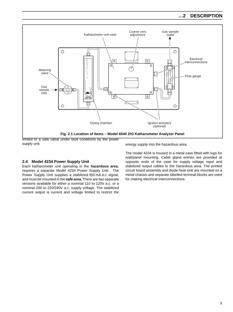
2.3 Model 6540 203 Katharometer Analyzer PanelThe gas monitoring system is certified for hydrogen purity andthere is a katharometer analyzer panel in the hazardous area .
The panel has a katharometer assembly which comprises athermally lagged katharometer type 6539-960, a meteringvalve, a flowmeter and a drying chamber. These items aremounted on a flat panel suitable for fixing to a vertical surfaceclose to the sample point – see Fig. 2.1.
The katharometer is calibrated for hydrogen puritymeasurement.
The inlet and outlet gas unions to the katharometer unit maybe provided with ignition arresters (Model 6540 203/J), butthese are not a necessary part of the certification. Thekatharometer analyzer panel not provided with ignitionarresters is the Model 6540 203/K.
The sealed katharometer assembly incorporates aWheatstone Bridge made up of fine, glass-coated platinumfilaments. One pair of parallel arms is sealed in reference gas(hydrogen) and the other pair exposed to the sample gas.
When the intrinsically safe stabilised current from the powersupply unit (Model 4234) is passed through this bridge, thetemperature of the platinum filaments rises to a point ofthermal equilibrium. Under conditions which are arranged togive minimum radiation and convection heat transfer, theequilibrium temperature depends on the thermal conductivityof the gas surrounding the filament. Thus any differencebetween the thermal conductivity of reference and samplegases causes an imbalance in the bridge; this imbalance (as amillivolt signal) is indicated by the display unit.
Zener diodes are connected across the input connections fromthe power supply unit to the katharometer in order to limit themaximum voltage which could be developed across thefilament bridge under external fault conditions. The current is
3
…2 DESCRIPTION
Fig. 2.1 Location of Items – Model 6540 203 Katharometer Analyzer Panel
Electricalinterconnections
Flow gauge
Ignition arresters(optional)
Gas sampleoutlet
Coarse zeroadjustment
Drying chamber
Katharometer unit case
Meteringvalve
Gassample
inlet
limited to a safe value under fault conditions by the powersupply unit.
2.4 Model 4234 Power Supply UnitEach katharometer unit operating in the hazardous area ,requires a separate Model 4234 Power Supply Unit. ThePower Supply Unit supplies a stabilized 350 mA d.c. signal,and must be mounted in the safe area . There are two separateversions available for either a nominal 110 to 120V a.c. or anominal 200 to 220/240V a.c. supply voltage. The stabilizedcurrent output is current and voltage limited to restrict the
energy supply into the hazardous area.
The model 4234 is housed in a metal case fitted with lugs forwall/panel mounting. Cable gland entries are provided atopposite ends of the case for supply voltage input andstabilized output cables to the hazardous area. The printedcircuit board assembly and diode heat sink are mounted on ametal chassis and separate labelled terminal blocks are usedfor making electrical interconnections.
4
3 PREPARATION
The circuit is protected by a cartridge fuse which must have a high breaking capacity (hbc) rating of 4000A to comply with theterms of the certification.
3.1 IdentificationIt is essential that installers and users identify the various units of the monitoring system as follows:
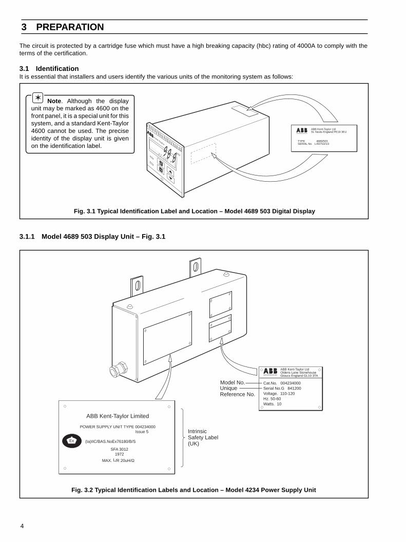
3.1.1 Model 4689 503 Display Unit – Fig. 3.1
Fig. 3.1 Typical Identification Label and Location – Model 4689 503 Digital Display
Note . Although the displayunit may be marked as 4600 on thefront panel, it is a special unit for thissystem, and a standard Kent-Taylor4600 cannot be used. The preciseidentity of the display unit is givenon the identification label.
ASEA BROWN BOVERI
ABB Kent-Taylor LtdSt. Neots England PE19 3EU
TYPE 4689/503SERIAL No. L/50753/1/3
98.8H 2
– C O 2
Kent-Taylor
4600
Fig. 3.2 Typical Identification Labels and Location – Model 4234 Power Supply Unit
Ex
ABB Kent-Taylor Limited
POWER SUPPLY UNIT TYPE 004234000 Issue 5
(Ia)IIC/BAS.NoEx76180/B/S
SFA 30121972
MAX. L/R 20uH/Ω
ASEA BROWN BOVERI
ABB Kent-Taylor LtdOldens Lane StonehouseGloucs England GL10 3TA
Cat.No. 004234000Serial No.G 841200Voltage. 110-120Hz. 50-60Watts. 10
IntrinsicSafety Label(UK)
Model No.UniqueReference No.
5
…3 PREPARATION
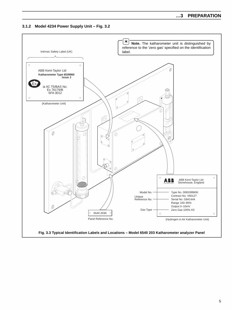
3.1.2 Model 4234 Power Supply Unit – Fig. 3.2
ABB Kent-Taylor Ltd
ia IIC T5/BAS No.Ex 76179/BSFA 3012
Katharometer Type 6539960 Issue J
Ex
ABB Kent-Taylor LtdStonehouse, England
Type No. 006539960KContract No. V60127Serial No. G841444Range 100–85%Output 0–10mVZero Gas 100% H2
6540 203K
Intrinsic Safety Label (UK)
(Katharometer Unit)
Model No.
UniqueReference No.
Gas Type
Panel Reference No. (Hydrogen in Air Katharometer Unit)
ASEA BROWN BOVERI
Note. The katharometer unit is distinguished byreference to the 'zero gas' specified on the identificationlabel.
Fig. 3.3 Typical Identification Labels and Locations – Model 6540 203 Katharometer analyzer Panel
6
4 MECHANICAL INSTALLATION
3.1.3 Model 6540 203 Katharometer Analyzer Panel – Fig. 3.3
4.1 Locating and Mounting System Items
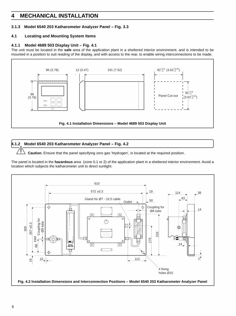
4.1.1 Model 4689 503 Display Unit – Fig. 4.1The unit must be located in the safe area of the application plant in a sheltered interior environment, and is intended to bemounted in a position to suit reading of the display, and with access to the rear, to enable wiring interconnections to be made.
4.1.2 Model 6540 203 Katharometer Analyzer Panel – Fig. 4.2
Caution. Ensure that the panel specifying zero gas 'Hydrogen', is located at the required position.
The panel is located in the hazardous area (zone 0,1 or 2) of the application plant in a sheltered interior environment. Avoid alocation which subjects the katharometer unit to direct sunlight.
Fig. 4.1 Installation Dimensions – Model 4689 503 Display Unit
Fig. 4.2 Installation Dimensions and Interconnection Positions – Model 6540 203 Katharometer Analyzer Panel
43
14
114 38
2
14
610
572 ±0.3
Gland for Ø7 - 10.5 cable
11210
19
305
267
±0.3
Cou
plin
g fo
rØ
8 tu
be
Inle
t98
179
233
Outlet
Coupling forØ8 tube
4 fixingholes Ø10
19
50
191 (7.52)12 (0.47)
Panel Cut-out
96 (3.78)
96(3.78)
+0.8–092
(3.62 )+0.03–0
+0.8–092 (3.62 )+0.03
–0

7
…4 MECHANICAL INSTALLATION
The katharometer unit is fixed to the panel which has fixing holes at each corner and should be mounted on a suitable verticalsurface close to the sample tapping point.4.1.3 Model 4234 Power Supply Unit – Fig. 4.3The unit must be located in the safe area of the application plant in a sheltered interior environment. It has four fixing lugs andshould be mounted on a suitable vertical surface.
4.2 Sample Gas Interconnections
Warning . A hazardous mixture of hydrogen in air could develop in the event of leakage from the sample gas system.Katharometer analyzer panels should be located in a ventilated area.
The sample pressure must not exceed the value given in Section 13.
The incoming sample gas temperature must not exceed the temperature given in Section 13.
If there is a risk of significant particle contamination, a suitable 1µm filter unit should be incorporated in the system before thesample gas enters the analyzer.
Fig. 4.3 Installation Dimensions and Interconnection Positions – Model 4234 Power Supply Unit
283
50 160 ± 1
230
194
± 0.
5
148
26Power in2
Gla
nds
for
Ø7
10.5
cabl
e
Regulated power out
10.5
20
26
55
135
Gland positions foralternative orientation of unit
8
5 ELECTRICAL INSTALLATION
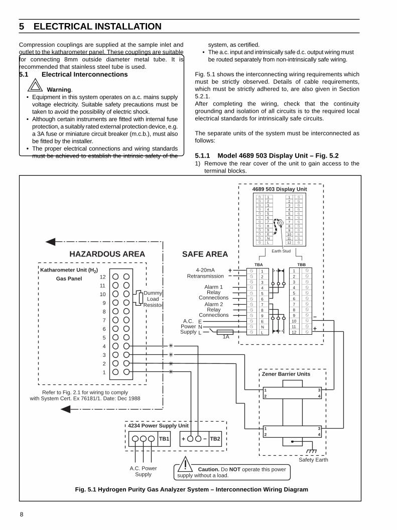
system, as certified.• The a.c. input and intrinsically safe d.c. output wiring must
be routed separately from non-intrinsically safe wiring.
Fig. 5.1 shows the interconnecting wiring requirements whichmust be strictly observed. Details of cable requirements,which must be strictly adhered to, are also given in Section5.2.1.After completing the wiring, check that the continuitygrounding and isolation of all circuits is to the required localelectrical standards for intrinsically safe circuits.
The separate units of the system must be interconnected asfollows:
5.1.1 Model 4689 503 Display Unit – Fig. 5.21) Remove the rear cover of the unit to gain access to the
terminal blocks.
Fig. 5.1 Hydrogen Purity Gas Analyzer System – Interconnection Wiring Diagram
123456789ENL
1 2 3 4 5 6 7 8 9101112
12
11
10
9
8
7
6
5
4
3
2
1
Katharometer Unit (H 2)
Gas Panel
SAFE AREAHAZARDOUS AREA
1
2
1
2
3
4
3
4
DummyLoad
Resistor
Zener Barrier Units
Safety Earth
A.C. PowerSupply
TB1 TB2
Refer to Fig. 2.1 for wiring to complywith System Cert. Ex 76181/1. Date: Dec 1988
Caution. Do NOT operate this powersupply without a load.
4234 Power Supply Unit
4689 503 Display Unit
Earth Stud
TBA
123456789ENL
1 2 3 4 5 6 7 8 9101112
TBB
Alarm 1Relay
ConnectionsAlarm 2Relay
Connections
4-20mARetransmission
LNE
1A
A.C.PowerSupply
Compression couplings are supplied at the sample inlet andoutlet to the katharometer panel. These couplings are suitablefor connecting 8mm outside diameter metal tube. It isrecommended that stainless steel tube is used.5.1 Electrical Interconnections
Warning .• Equipment in this system operates on a.c. mains supply
voltage electricity. Suitable safety precautions must betaken to avoid the possibility of electric shock.
• Although certain instruments are fitted with internal fuseprotection, a suitably rated external protection device, e.g.a 3A fuse or miniature circuit breaker (m.c.b.), must alsobe fitted by the installer.
• The proper electrical connections and wiring standardsmust be achieved to establish the intrinsic safety of the

9
5 ELECTRICAL INSTALLATION…
Fig. 5.3 Location of Components inside Case – Model 6539 960 Katharometer Unit
Coarse zeroadjustment
Measuringunit
Tubingconnections
Terminal block (TB1)
Dummyload
resistor
Mounting pillars
2) Make the wiring connections in accordance with the information given in the wiring diagram Fig. 5.1 and Section 5.
5.1.2 Model 6540 203 Katharometer Analyzer Panel – Fig. 5.3All the electrical connections are made inside the katharometer unit (6539 960) on the analyzer panel.
1) Remove the cover of the katharometer unit to gain access to the terminal block (TB1) inside.
Fig. 5.2 Access to Terminals – Model 4689 503 Display Unit
Remove nuts andprotection cover
1
Removemains cover
2
Mains Cover

10
…5 ELECTRICAL INSTALLATION
2) Make the electrical connections in accordance with theinformation given in wiring diagram Fig. 5.1 and Section5.2.1.
Note . The electrical connections are made at theterminal block (TB1) via the cable gland, or anyreplacement gland to suit the intrinsically safe wiringrequirements.
1) Remove the 510R dummy load resistor from acrossterminals 9 and 10, when the appropriate interconnectionshave been made.
2) Replace the cover of the katharometer unit on completionof wiring up.
5.1.3 Model 4234 Power Supply Unit – Fig. 5.4
Warning . Do not connect mains supply to the powersupply unit with the output terminals open circuit. Thiscauses premature component failure.
Caution . Ensure that the power supply unit iscorrect for the mains supply voltage available. A nominal110V unit cannot be adapted for use with a nominal 240Vsupply, or the other way around.
1) Remove the cover of the unit to gain access to the terminalblocks inside.
2) Locate the terminal block (TB3) adjacent to the transformerT1. If necessary, adjust the transformer tapping to thecorrect incoming supply 110/120V,200/220V or 240V bymoving the brown wire to the appropriately markedterminal of TB3.
3) Make electrical connections in accordance with theinformation given in the wiring diagram Fig. 5.1 and Section5.2.1.
Note. The electrical connections are made atterminal blocks TB1 and TB2 through the appropriatecable gland, or any replacement gland to suit intrinsicallysafe wiring requirements.
4) Secure the incoming cable by the cable clips adjacent tothe terminal blocks.
5) Fit the cover on completion of wiring up.
5.2 Intrinsically Safe RequirementsThese requirements relate to the interconnecting wiring madeto and from the Model 6540 203 Katharometer Analyzer Panelin the hazardous area, and those for remote ancillary itemsconnected to the system.
5.2.1 Cable RequirementsThe interconnecting cables between the various units of thesystem are subject to stringent limitations because of therequirements of the intrinsic safety certification. These follow
Fig. 5.4 Location of Components inside Case – Model 4234 Power Supply Unit
Spare fuse
FS1
Inputterminals
(TB1)
Cable clampVoltage selectionterminals (TB3)
Cable clamp
Outputterminals
(TB2)
R103
C101 R101 D102 R104 RV101
D101
R102
TR101
Z101
D103
C102 C103
11
5E
LEC
TR
ICA
L INS
TALLAT
ION
…
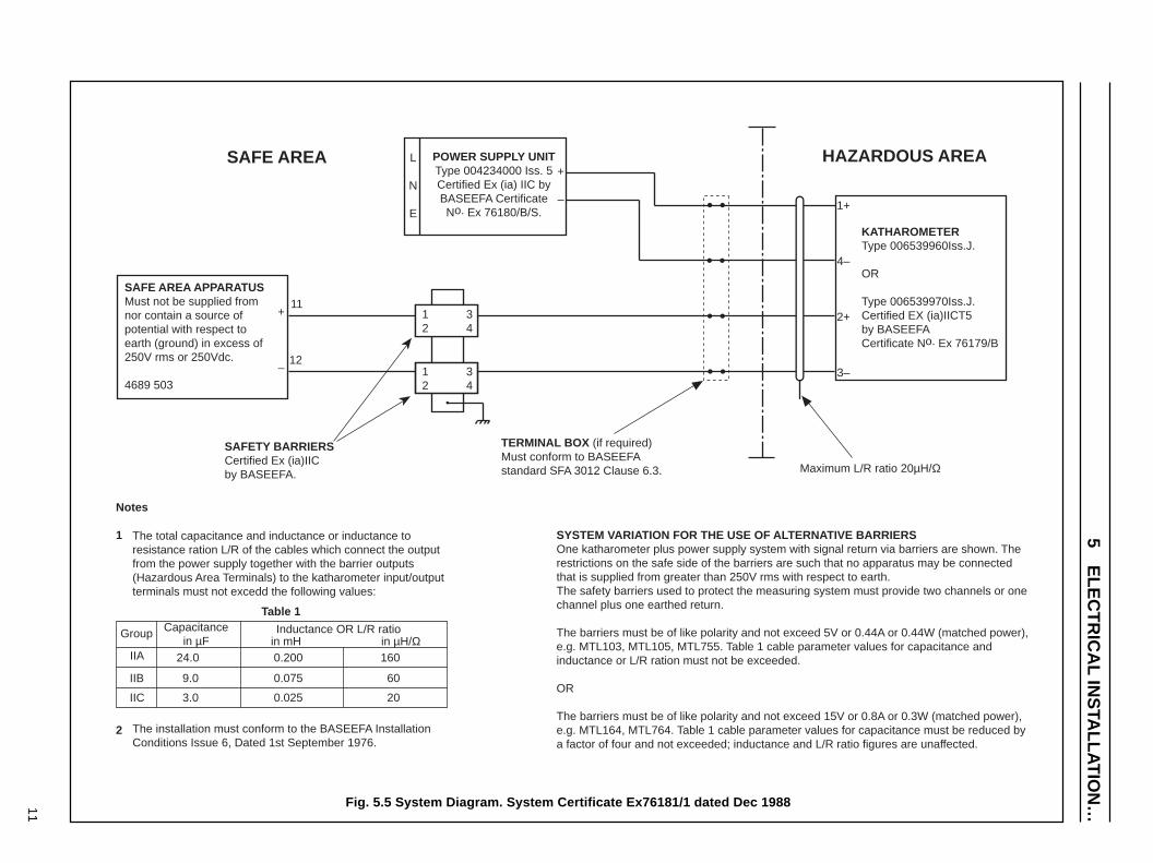
Fig. 5.5 System Diagram. System Certificate Ex76181/1 dated Dec 1988
Notes
1
2
The total capacitance and inductance or inductance to resistance ration L/R of the cables which connect the output from the power supply together with the barrier outputs (Hazardous Area Terminals) to the katharometer input/output terminals must not excedd the following values:
The installation must conform to the BASEEFA Installation Conditions Issue 6, Dated 1st September 1976.
Group Capacitancein µF
Inductance OR L/R ratioin mH in µH/Ω
IIA
IIB
IIC
24.0
9.0
3.0
0.200
0.075
0.025
160
60
20
KATHAROMETERType 006539960Iss.J.
OR
Type 006539970Iss.J.Certified EX (ia)IICT5by BASEEFACertificate No. Ex 76179/B
1+
4–
2+
3–
POWER SUPPLY UNITType 004234000 Iss. 5Certified Ex (ia) IIC byBASEEFA CertificateNo. Ex 76180/B/S.
L
N
E
+
–
HAZARDOUS AREASAFE AREA
SAFETY BARRIERSCertified Ex (ia)IICby BASEEFA.
TERMINAL BOX (if required)Must conform to BASEEFAstandard SFA 3012 Clause 6.3. Maximum L/R ratio 20µH/Ω
11
12
Table 1
SYSTEM VARIATION FOR THE USE OF ALTERNATIVE BARRIERSOne katharometer plus power supply system with signal return via barriers are shown. The restrictions on the safe side of the barriers are such that no apparatus may be connected that is supplied from greater than 250V rms with respect to earth.The safety barriers used to protect the measuring system must provide two channels or one channel plus one earthed return.
The barriers must be of like polarity and not exceed 5V or 0.44A or 0.44W (matched power), e.g. MTL103, MTL105, MTL755. Table 1 cable parameter values for capacitance and inductance or L/R ration must not be exceeded.
OR
The barriers must be of like polarity and not exceed 15V or 0.8A or 0.3W (matched power), e.g. MTL164, MTL764. Table 1 cable parameter values for capacitance must be reduced by a factor of four and not exceeded; inductance and L/R ratio figures are unaffected.
12
34
12
34
SAFE AREA APPARATUSMust not be supplied from nor contain a source of potential with respect to earth (ground) in excess of 250V rms or 250Vdc.
4689 503
+
–
12
…5 ELECTRICAL INSTALLATION
and are also detailed in Fig. 5.5.
All cables entering the hazardous area, MUST be kept separatefrom cables in the safe area . Cables entering the hazardousarea, MUST NOT be run with other cables, and terminations musthave a grounded screen to separate them from connections forother circuits.The detailed requirements are as follows:
1) Connections between Model 6540 203 KatharometerAnalyzer Panel and Model 4234 Power Supply Unit.All cables from the Katharometer into the hazardous areamust have an inductance/resistance ratio not exceeding18µH/Ω, (for Group IIC gases). There is a further requirementthat the maximum resistance of this interconnecting cable islimited to 2Ω. This may place a limitation on the length of thetotal cable run. Single sheathed conducting cables should betwisted together to reduce their mutual inductance, androuted separately from cabling for non-intrinsically safecircuits in the safe area.
2) Connections between Model 6540 203 KatharometerAnalyzer Panel, Zener Barrier Unit and Model 4689 503Display Unit.No special requirements are necessary to limit the choice ofcable for the interconnection between the katharometer zeroadjustment controls and the display unit.
5.2.2 Recommended CablesThe limitations imposed restrict the choice of wiring cable to a fewtypes. 'Pyrotenax' meet the requirements of less than 18µH/Ω with their mineral insulated cable type PCC 2L1.
Kent-Taylor should be consulted with information on any othercables proposed for use in the installation of this system.
Detailed cable specifications of the above mentioned type is
available from:Pyrotenax LimitedHedgeley RoadHebburn-on-TyneCounty DurhamTelephone: 091 483 4123
5.2.3 Full Intrinsically Safe RequirementsFor systems to be modified or used with other gases the fullBASEEFA requirements must be complied with as follows:
1) The total Capacitance and Inductance or Inductance toResistance ratio (L/R) of the cables connecting thekatharometer unit to the display unit and power supply unitterminals (TB1), must not exceed the values given in Table5.1.
2) Any terminal boxes used in the hazardous or safe areas mustconform to BASEEFA Standard SFA.3012, clause 6.3.
3) The overall installation must conform to the BASEEFAinstallation conditions, Issue 6 (September 1976) – see Fig.5.5
Table 5.1 6553 – Intrinsically Safe Wiring Requirements
Gas GroupCapacitance
µFInductance
mH
Inductance/Resistance
µH/ΩIIA 4.8 0.152 144
IIB 1.8 0.057 54
IIC 0.6 0.019 18
13
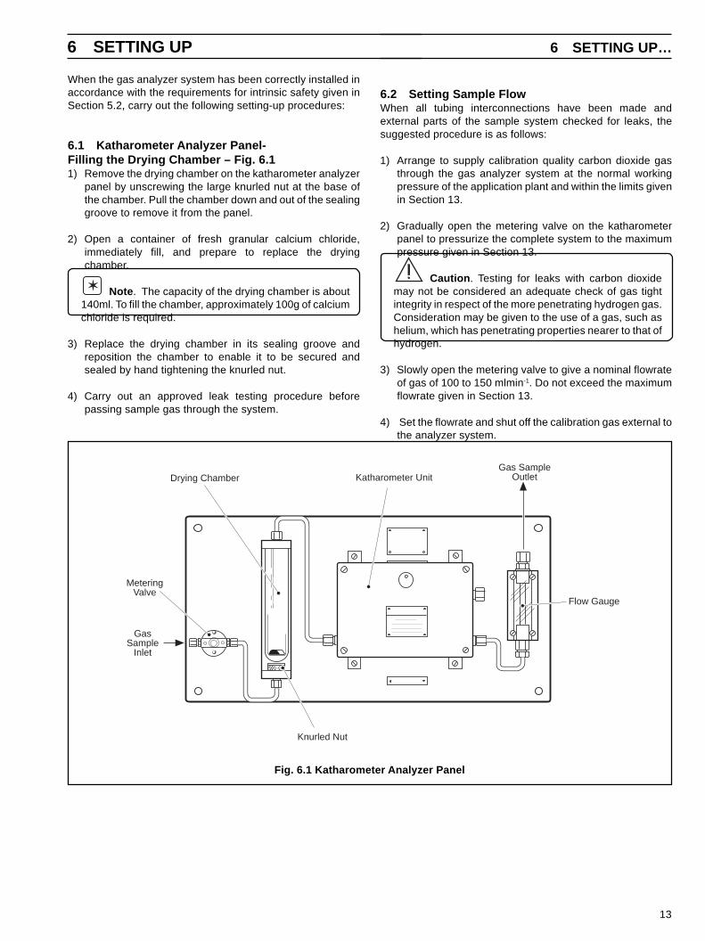
6.2 Setting Sample FlowWhen all tubing interconnections have been made andexternal parts of the sample system checked for leaks, thesuggested procedure is as follows:
1) Arrange to supply calibration quality carbon dioxide gasthrough the gas analyzer system at the normal workingpressure of the application plant and within the limits givenin Section 13.
2) Gradually open the metering valve on the katharometerpanel to pressurize the complete system to the maximumpressure given in Section 13.
Caution . Testing for leaks with carbon dioxidemay not be considered an adequate check of gas tightintegrity in respect of the more penetrating hydrogen gas.Consideration may be given to the use of a gas, such ashelium, which has penetrating properties nearer to that ofhydrogen.
3) Slowly open the metering valve to give a nominal flowrateof gas of 100 to 150 mlmin-1. Do not exceed the maximumflowrate given in Section 13.
4) Set the flowrate and shut off the calibration gas external tothe analyzer system.
Fig. 6.1 Katharometer Analyzer Panel
Flow Gauge
Gas SampleOutletDrying Chamber
MeteringValve
GasSample
Inlet
Katharometer Unit
Knurled Nut
When the gas analyzer system has been correctly installed inaccordance with the requirements for intrinsic safety given inSection 5.2, carry out the following setting-up procedures:
6.1 Katharometer Analyzer Panel-Filling the Drying Chamber – Fig. 6.11) Remove the drying chamber on the katharometer analyzer
panel by unscrewing the large knurled nut at the base ofthe chamber. Pull the chamber down and out of the sealinggroove to remove it from the panel.
2) Open a container of fresh granular calcium chloride,immediately fill, and prepare to replace the dryingchamber.
Note . The capacity of the drying chamber is about140ml. To fill the chamber, approximately 100g of calciumchloride is required.
3) Replace the drying chamber in its sealing groove andreposition the chamber to enable it to be secured andsealed by hand tightening the knurled nut.
4) Carry out an approved leak testing procedure beforepassing sample gas through the system.
6 SETTING UP 6 SETTING UP…
14
…6 SETTING UP
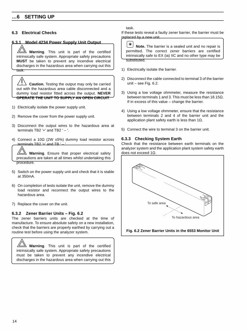
task.If these tests reveal a faulty zener barrier, the barrier must bereplaced by a new unit.
Note. The barrier is a sealed unit and no repair ispermitted. The correct zener barriers are certifiedintrinsically safe to EX (ia) IIC and no other type may besubstituted.
1) Electrically isolate the barrier.
2) Disconnect the cable connected to terminal 3 of the barrierunit – see Fig. 6.2.
3) Using a low voltage ohmmeter, measure the resistancebetween terminals 1 and 3. This must be less than 18.15Ω.If in excess of this value – change the barrier.
4) Using a low voltage ohmmeter, ensure that the resistancebetween terminals 2 and 4 of the barrier unit and theapplication plant safety earth is less than 1Ω.
5) Connect the wire to terminal 3 on the barrier unit.
6.3.3 Checking System EarthCheck that the resistance between earth terminals on theanalyzer system and the application plant system safety earthdoes not exceed 1Ω.
6.3 Electrical Checks
6.3.1 Model 4234 Power Supply Unit Output
Warning . This unit is part of the certifiedintrinsically safe system. Appropriate safety precautionsMUST be taken to prevent any incendive electricaldischarges in the hazardous area when carrying out thistask.
Caution. Testing the output may only be carriedout with the hazardous area cable disconnected and adummy load resistor fitted across the output. NEVEROPERATE THE UNIT TO SUPPLY AN OPEN CIRCUIT .
1) Electrically isolate the power supply unit.
2) Remove the cover from the power supply unit.
3) Disconnect the output wires to the hazardous area atterminals TB2 '+' and TB2 ' – '.
4) Connect a 10Ω (2W ±5%) dummy load resistor acrossterminals TB2 '+' and TB ' – '.
Warning . Ensure that proper electrical safetyprecautions are taken at all times whilst undertaking thisprocedure.
5) Switch on the power supply unit and check that it is stableat 350mA.
6) On completion of tests isolate the unit, remove the dummyload resistor and reconnect the output wires to thehazardous area.
7) Replace the cover on the unit.
6.3.2 Zener Barrier Units – Fig. 6.2The zener barriers units are checked at the time ofmanufacture. To ensure absolute safety on a new installation,check that the barriers are properly earthed by carrying out aroutine test before using the analyzer system.
Warning . This unit is part of the certifiedintrinsically safe system. Appropriate safety precautionsmust be taken to prevent any incendive electricaldischarges in the hazardous area when carrying out this
Fig. 6.2 Zener Barrier Units in the 6553 Monitor Unit
To safe area
To hazardous area
4 3
12
15
7 CONTROLS AND DISPLAYS
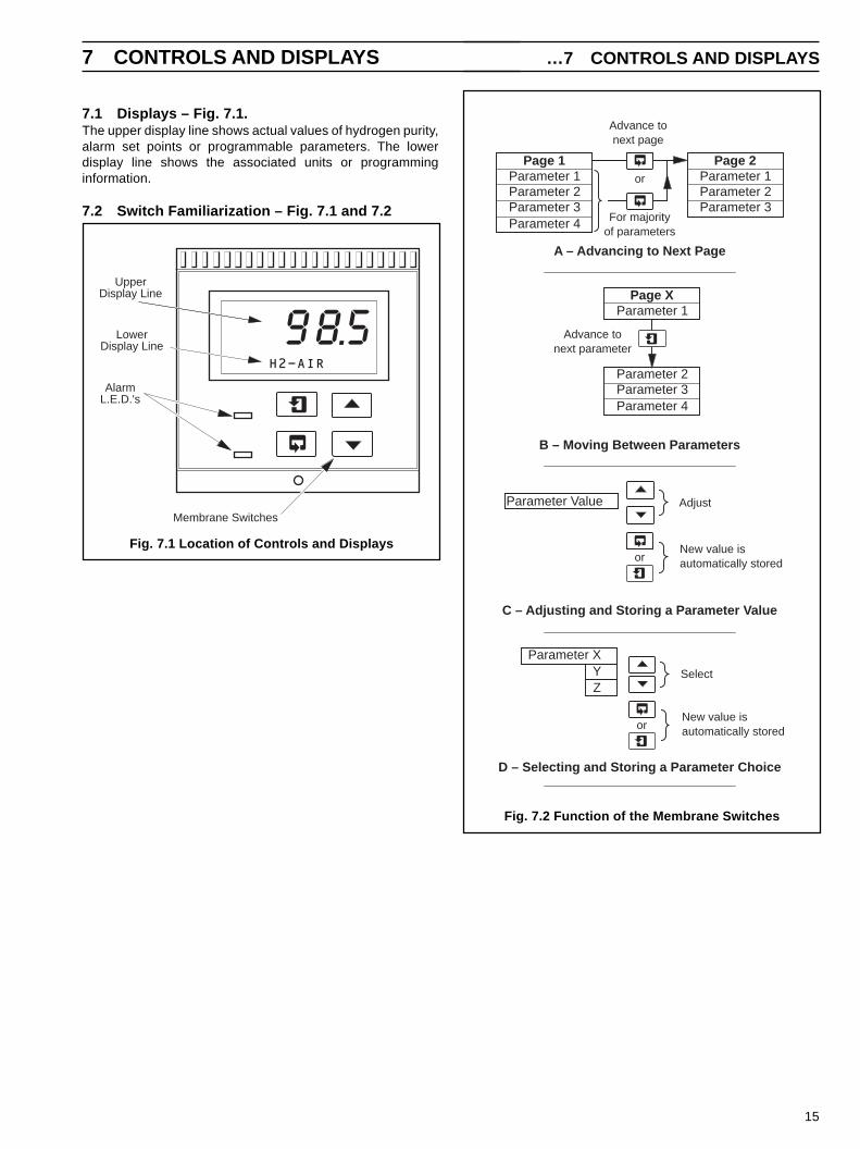
A – Advancing to Next Page
Parameter 1Parameter 2Parameter 3Parameter 4
Page 1Parameter 1Parameter 2Parameter 3
Page 2
Advance tonext page
For majorityof parameters
or
B – Moving Between Parameters
C – Adjusting and Storing a Parameter Value
New value isautomatically stored
Parameter Value Adjust
D – Selecting and Storing a Parameter Choice
Parameter XYZ
Select
Parameter 1
Parameter 2Parameter 3
Page X
Parameter 4
Advance tonext parameter
or
New value isautomatically storedor
Fig. 7.2 Function of the Membrane Switches
7.1 Displays – Fig. 7.1.The upper display line shows actual values of hydrogen purity,alarm set points or programmable parameters. The lowerdisplay line shows the associated units or programminginformation.
7.2 Switch Familiarization – Fig. 7.1 and 7.2
…7 CONTROLS AND DISPLAYS
98.5H2-AIR
AlarmL.E.D.'s
UpperDisplay Line
LowerDisplay Line
Membrane Switches
Fig. 7.1 Location of Controls and Displays

16
8 START-UP
Warning . When the apparatus is connected to itssupply, terminals may be live, and the opening of coversor removal of parts (except those to which access may begained by hand) is likely to expose live parts.
8.1 Instrument Start-upIn normal operation the instrument displays the OperatingPage which is a general use page in which parameters areviewed only and cannot be altered. Any changes to theoperating parameters are implemented using the switches asdescribed in Section 7.2. To alter or program a parameter referto Section 10. A 5-digit Security Code is used to preventunauthorised access to programmable parameters. The valueis preset at 00000 to allow access during commissioning butshould be altered to a unique value, known only to authorizedoperators, as described in Section 10.4.
When all the required wiring connections and electrical checkshave been correctly made, the power supplies to the variousunits may be switched on as follows:
1) Switch on the supply voltage to the Power Supply Unit.
2) Switch on the supply voltage to the Display Unit.
8.2 Alarm Set Points
8.2.1 Type of Alarm ActionThe alarm relay coil is energized during normal non-alarmrelay states and is de-energized upon recognition of an alarmcondition, thereby providing 'fail-safe' alarms. i.e. with Alarm 1set point = 95.0, when the display is indicating greater than95.0 (plus hysteresis), then Alarm Relay 1 is energized andAlarm 1 LED is OFF. When the display indicates less than 95.0(minus hysteresis), then Alarm Relay 1 is de-energized andAlarm 1 LED is ON. This operating mode ensures that, in theevent of a mains power failure, an alarm condition is signalled.
8.2.2 HydrogenIt is suggested that the hydrogen alarm set-points should bebased on a reducing percentage of hydrogen as it is displacedby air entering the application plant. This can be achieved bysetting Alarm 1 and Alarm 2 to give ample warning of thedevelopment of a potentially explosive mixture. Factorysettings are: Alarm 1 = 95.0 and Alarm 2 = 90.0.
1) Access the programming pages and input the alarm set-
points in accordance with the information given in Section10.2.
8.3 CalibrationBefore putting the system on-line, carry out a calibration check onthe zero input signal using calibration sample gas. The maximuminput signal for the full range reading is preset during manufactureand sealed.
Caution . These sealed adjustments must NOTbe altered by users.
Note . The 4600 Series instruments incorporate a twopoint calibration sequence requiring both zero and spaninputs for a calibration. It is not possible to adjust either therange zero or the range span scale points independently.
The local coarse 'zero' adjusters at the katharometer units in thehazardous area are redundant when this adjustment istransferred to the gas monitor unit. The potentiometers in thekatharometer units should be set to the midpoint on installationand sealed off. A summary of the system functions and calibrationdata is given in Table 8.1.
8.3.1 Hydrogen
Warning . Test for leaks in accordance with therequirements of the responsible authority after making anyhydrogen connections.
1) Arrange to pass calibration quality Hydrogen gas through theKatharometer Unit at the normal working pressure of thesample gas system. This should give the correct flowrate ofgas, as set previously.
2) Power up the display unit, and switch on the power supply unitto power up the katharometer unit.
3) The display unit will indicate the measurement parameter -percentage by volume of hydrogen in air (H2 - AIR). The upperdisplay line will indicate a value for the parameter.
4) With hydrogen calibration gas passing through the samplesystem at the normal flowrate, the upper display line of thedisplay unit should stabilize within 2 hours to read 100.0 .
5) If necessary, refer to Section 10.3 for a full calibrationsequence.
Note . A coarse zero adjustment facility is available
* – As specified for application ‡ – Not user adjustable
Table 8.1 System functions and Calibration Settings
‡
*
FunctionNo mV output at Katharometer 10 mV output at Katharometer
Calibration Gas Calibration Setting Calibration Gas Calibration Setting
%H2 in AIR
100% H2 100.0 -80%
or85%
17
9 OPERATION
at the top 'zero' potentiometer. Adjustment is made byinserting a screwdriver through the hole behind the smallescutcheon plate.
9.1 NormalDuring normal operation the Gas Analyzer System is used toindicate the purity of hydrogen used as a coolant. The displayunit shows the percentage of hydrogen in air, which should besafely in excess of the explosive limit at the hydrogen rich end.
There are no routine adjustments required to the gas analyzersystem after completion of start-up procedures and putting on-line in monitoring mode. The system only requires minoradjustments to the metering valve to maintain the requiredflowrate and the carrying out of safety routines.
9.2 Purging of Hydrogen Coolant GasWhen the hydrogen coolant has to be removed from theapplication plant, it is wasteful and dangerous to release thecoolant gas directly into the atmosphere. It is thereforenecessary to ensure that the system is outside the explosivelimits for air-in-hydrogen before allowing air into the system.
Initially, inert purge gas (carbon dioxide) is introduced into thesystem. When the hydrogen concentration is safely below theexplosive limit, air is introduced into the system to completelydisplace the other two gases.
A Model 6553 Gas Analyzer System is available whichprovides all the necessary indications and output signals toenable this operation to be carried out safely.
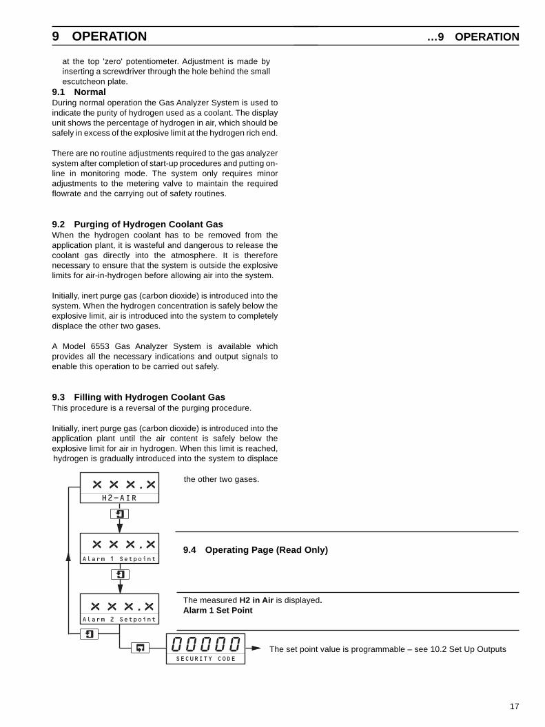
9.3 Filling with Hydrogen Coolant GasThis procedure is a reversal of the purging procedure.
Initially, inert purge gas (carbon dioxide) is introduced into theapplication plant until the air content is safely below theexplosive limit for air in hydrogen. When this limit is reached,hydrogen is gradually introduced into the system to displace
the other two gases.
9.4 Operating Page (Read Only)
The measured H2 in Air is displayed.Alarm 1 Set Point
The set point value is programmable – see 10.2 Set Up Outputs
Alarm 1 Setpoint
Alarm 2 Setpoint
0 0 0 0 0SECURITY CODE
xxx . xH2-AIR
xxx . x
x xx . x
…9 OPERATION
18
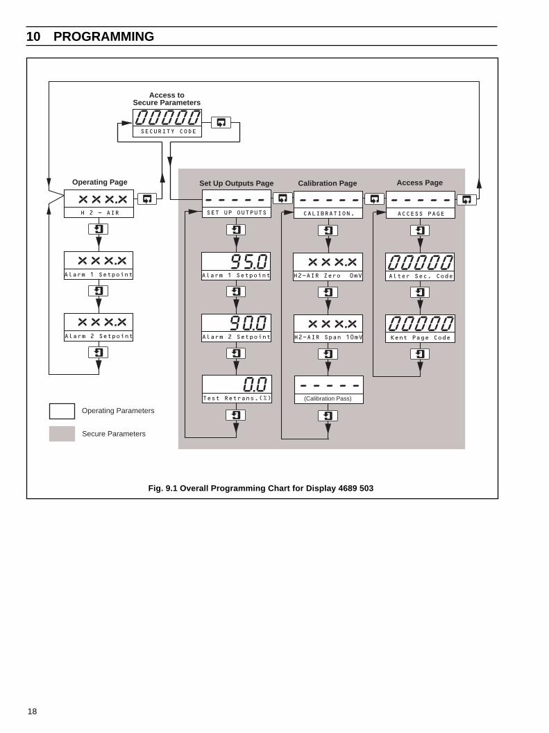
Fig. 9.1 Overall Programming Chart for Display 4689 503
10 PROGRAMMING
Operating Page
SET UP OUTPUTS
SECURITY CODE
Alarm 1 Setpoint
H 2 - AIR
Alarm 2 Setpoint
or
Alarm 1 Setpoint
Alarm 2 Setpoint
90.0
or
Test Retrans.(%)
0.0
CALIBRATION.
H2-AIR Zero 0mV
(Calibration Pass)
ACCESS PAGE
Alter Sec. Code
Kent Page CodeH2-AIR Span 10mV
00000
Set Up Outputs Page Calibration Page
Access toSecure Parameters
Access Page
00000
Operating Parameters
Secure Parameters
95.0
-----
00000
----- -----
-----
xxx.x
xxx.x
xxx.x
xxx.x
xxx.x
19
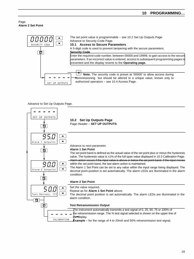
Page.Alarm 2 Set Point
The set point value is programmable – see 10.2 Set Up Outputs Page.Advance to Security Code Page.10.1 Access to Secure ParametersA 5-digit code is used to prevent tampering with the secure parameters.Security CodeEnter the required code number, between 00000 and 19999, to gain access to the secureparameters. If an incorrect value is entered, access to subsequent programming pages isprevented and the display reverts to the Operating page.
Note. The security code is preset at '00000' to allow access duringcommissioning but should be altered to a unique value, known only toauthorized operators – see 10.4 Access Page.
Advance to Set Up Outputs Page.
10.2 Set Up Outputs PagePage Header – SET UP OUTPUTS
Advance to next parameter.Alarm 1 Set PointThe set point band is defined as the actual value of the set point plus or minus the hysteresisvalue. The hysteresis value is ±1% of the full span value displayed in 10.3 Calibration Page.Alarm action occurs if the input value is above or below the set point band. If the input moveswithin the set point band, the last alarm action is maintained.The Alarm 1 Set Point can be set to any value within the input range being displayed. Thedecimal point position is set automatically. The alarm LEDs are illuminated in the alarmcondition.
Alarm 2 Set Point
Set the value required.Repeat as for Alarm 1 Set Point above.The decimal point position is set automatically. The alarm LEDs are illuminated in thealarm condition.
Test Retransmission Output
The instrument automatically transmits a test signal of 0, 25, 50, 75 or 100% ofthe retransmission range. The % test signal selected is shown on the upper line ofthe display.Example – for the range of 4 to 20mA and 50% retransmission test signal,
10 PROGRAMMING…
SECURITY CODE
SET UP OUTPUTS
-----
00000
SET UP OUTPUTS
-----
Alarm 1 Setpoint
95.0
Alarm 2 Setpoint
90.0
Test Retrans. (%)
CALIBRATION
-----
50.0
20
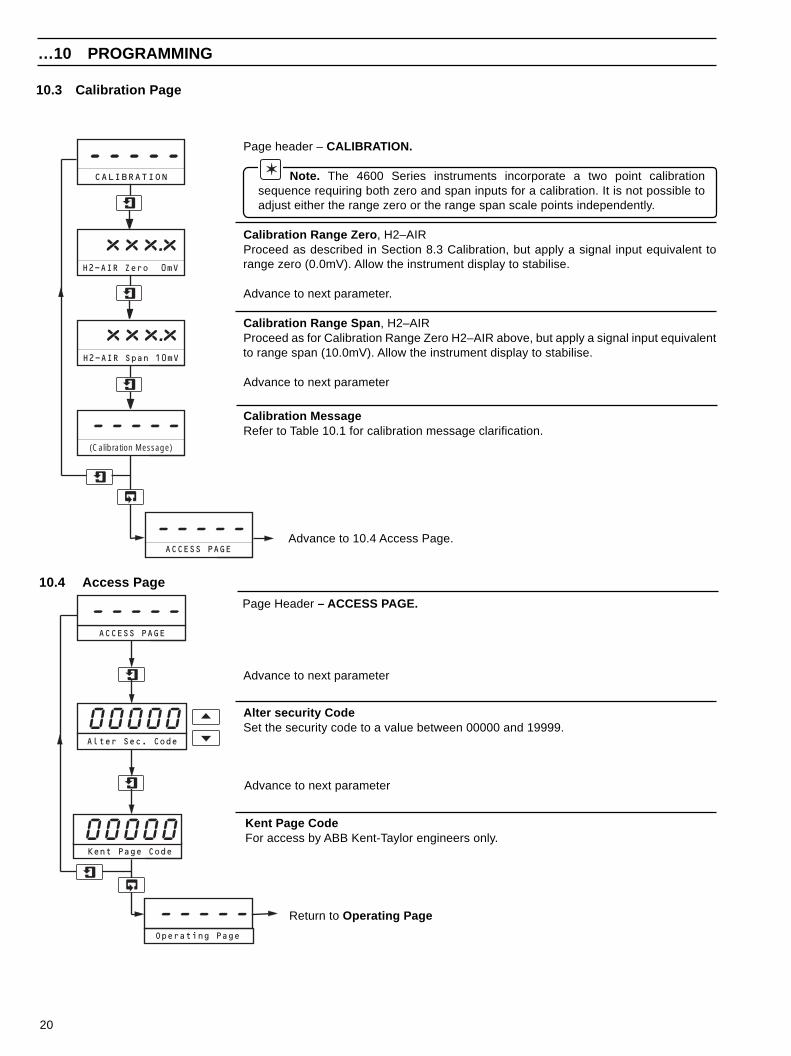
10.3 Calibration Page
10.4 Access Page
Page Header – ACCESS PAGE.
Advance to next parameter
Alter security CodeSet the security code to a value between 00000 and 19999.
Advance to next parameter
Kent Page CodeFor access by ABB Kent-Taylor engineers only.
Page header – CALIBRATION.
Note. The 4600 Series instruments incorporate a two point calibrationsequence requiring both zero and span inputs for a calibration. It is not possible toadjust either the range zero or the range span scale points independently.
Calibration Range Zero , H2–AIRProceed as described in Section 8.3 Calibration, but apply a signal input equivalent torange zero (0.0mV). Allow the instrument display to stabilise.
Advance to next parameter.
Calibration Range Span , H2–AIRProceed as for Calibration Range Zero H2–AIR above, but apply a signal input equivalentto range span (10.0mV). Allow the instrument display to stabilise.
Advance to next parameter
Calibration MessageRefer to Table 10.1 for calibration message clarification.
Return to Operating Page
…10 PROGRAMMING
CALIBRATION
-----
H2-AIR Zero 0mV
H2-AIR Span 10mV
xxx.x
(Calibration Message)
-----
ACCESS PAGE
-----
xxx.x
Advance to 10.4 Access Page.
ACCESS PAGE
Kent Page Code
Operating Page
-----
-----
00000Alter Sec. Code
00000

21
Table 10.1 Katharometer Calibration Messages for Section 10.3
Calibration Message Explanation Action
Calibrating... Calibration of new calibration coefficients None
Calibration Pass The new calibration coefficients are used None
H2-AIR Cal FailThe new calibration coefficients are ignored and the last known good calibration coefficients are used.
Repeat procedure with a calibrated mV source.If the problem persists, contact the Company
…10 PROGRAMMING
22
12mA is transmitted.Select the required retransmission test signal.
Advance to 10.3 Calibration Page.
Warning .• Each unit of this system forms an integral part of a certified
intrinsically safe system. Appropriate safety precautionsmust be taken to prevent any incendive electricaldischarges in the hazardous area when carrying out thesetasks.
• Equipment in this system operates on a.c. mains supplyvoltage electricity. Suitable precautions must be taken toavoid the possibility of electric shock.
• The maximum pressure and temperature specified forparticular parts of the system must not be exceeded.
The units are designed for stable and accurate operation overlong periods.
This section covers the requirements for fault finding, diagnostictests and maintenance tasks.
11.1 General Maintenance
11.1.1 PressureThe operation of the katharometer unit is not affected significantlyby changes in pressure providing it is within the pressure limitsgiven in Section 13.
11.1.2 FlowThe katharometer zero balance and sensitivity are independentof the sample flowrate, as the sample gas sensing systemdepends on molecular diffusion. But the speed of response isaffected by the flowrate. This means that the flow resistance of thedrying chamber is a compromise between obtaining speed ofresponse, and avoiding a rapid degradation of the desiccant.
11.1.3 LeaksThere is an inherent safety requirement that there are no leaksinto or out of the sample system. Any leaks could also affect thecorrect operation of the katharometer unit.
11.1.4 VibrationThe katharometer unit tolerates reasonable levels ofmechanically induced vibration. Pulsations due to unsteadysample flow can affect the katharometer filaments and causeerrors due to excessive cooling.
11.1.5 ContaminationContamination in the sample system can arise from oil orsuspended particles, or from erosion of material from the samplesystem upstream of the katharometer unit.
11.1.6 Ambient TemperatureThe calibration of the katharometer is not significantly affected byvariations of the ambient temperature. Temperature changes can
affect the sensitivity and reduce accuracy on sensitive ranges.
11.1.7 Bridge CurrentThe working current of the katharometer bridge is 350mAsupplied from the power supply unit. This value must remainstable during normal operation as the katharometer output signalis approximately proportional to the cube of the bridge current.11.2 Diagnostic Tests
11.2.1 Checking Output of 4234 Power Supply UnitCarry out the test procedure given in Section 5.3.1 .
11.2.2 Checking Integrity of Zener Barrier UnitsCarry out the test procedure given in Section 5.3.2.
11.2.3 Checking the Katharometer Output
Warning .• This unit is part of the certified intrinsically safe system.
Appropriate safety precautions must be taken toprevent any incendive discharges in the hazardousarea when carrying out this task.
• Ensure that the proper electrical safety precautions aretaken at all times whilst undertaking this procedure.
1) Electrically isolate the display unit
2) Remove the outer cover from the 6539 960 katharometerunit.
3) With the katharometer operating, check if the voltageacross terminals TB1 - 1 and TB1 - 4 is not above 4V with350mA passing. If the voltage is above this value it is likelythat one or more filaments of the bridge is broken.
4) With the katharometer operating, check that the voltageacross terminals TB1 - 1 and TB1 - 4 is below 2.8V with350mA passing. If the voltage is below this value and thereis no zero adjustment available, it is likely that there is anaccumulation of liquid within the katharometer block.
5) If the reading from the test made at step 3) is unstablewhen the katharometer block is tapped gently, this couldindicate that a filament is damaged but not open circuit.
If any of these tests indicate that the katharometer is faulty thecomplete katharometer unit must be returned for repair orreplacement.
The sensitivity adjusters of katharometer units are sealed andmust not be tampered with.
11.3 Routine Maintenance
11.3.1 Hydrogen Katharometer CalibrationCarry out a calibration procedure in accordance with Section8.3.
11 MAINTENANCE
23
3) Remove the cover of the katharometer unit and dismantlethe internal sample system tubing.
4) Remove the fixing screws which secure the mountingpillars to the case – see Fig. 5.3.
5) Disconnect the interconnecting wiring at terminal blockTB1.
Caution . Do not insert any type of probe into thegas system of the measurement block or usecompressed air to blow through the system.
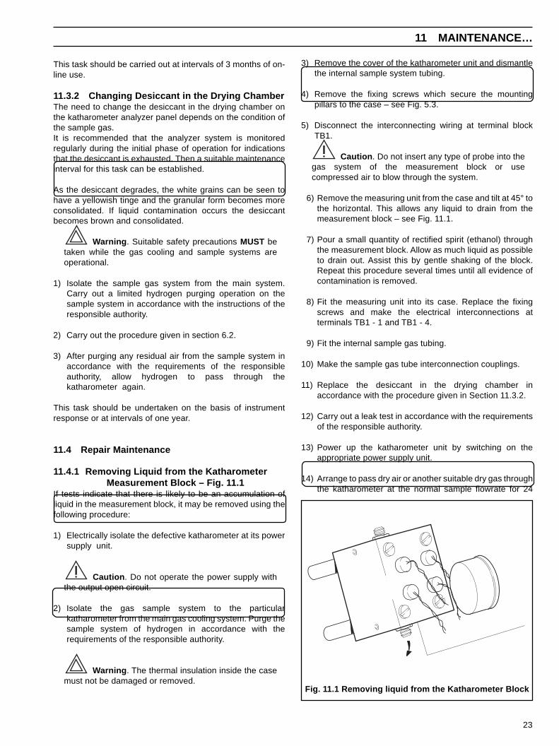
6) Remove the measuring unit from the case and tilt at 45° tothe horizontal. This allows any liquid to drain from themeasurement block – see Fig. 11.1.
7) Pour a small quantity of rectified spirit (ethanol) throughthe measurement block. Allow as much liquid as possibleto drain out. Assist this by gentle shaking of the block.Repeat this procedure several times until all evidence ofcontamination is removed.
8) Fit the measuring unit into its case. Replace the fixingscrews and make the electrical interconnections atterminals TB1 - 1 and TB1 - 4.
9) Fit the internal sample gas tubing.
10) Make the sample gas tube interconnection couplings.
11) Replace the desiccant in the drying chamber inaccordance with the procedure given in Section 11.3.2.
12) Carry out a leak test in accordance with the requirementsof the responsible authority.
13) Power up the katharometer unit by switching on theappropriate power supply unit.
14) Arrange to pass dry air or another suitable dry gas throughthe katharometer at the normal sample flowrate for 24
11 MAINTENANCE…
Fig. 11.1 Removing liquid from the Katharometer Block
This task should be carried out at intervals of 3 months of on-line use.
11.3.2 Changing Desiccant in the Drying ChamberThe need to change the desiccant in the drying chamber onthe katharometer analyzer panel depends on the condition ofthe sample gas.It is recommended that the analyzer system is monitoredregularly during the initial phase of operation for indicationsthat the desiccant is exhausted. Then a suitable maintenanceinterval for this task can be established.
As the desiccant degrades, the white grains can be seen tohave a yellowish tinge and the granular form becomes moreconsolidated. If liquid contamination occurs the desiccantbecomes brown and consolidated.
Warning . Suitable safety precautions MUST betaken while the gas cooling and sample systems areoperational.
1) Isolate the sample gas system from the main system.Carry out a limited hydrogen purging operation on thesample system in accordance with the instructions of theresponsible authority.
2) Carry out the procedure given in section 6.2.
3) After purging any residual air from the sample system inaccordance with the requirements of the responsibleauthority, allow hydrogen to pass through thekatharometer again.
This task should be undertaken on the basis of instrumentresponse or at intervals of one year.
11.4 Repair Maintenance
11.4.1 Removing Liquid from the KatharometerMeasurement Block – Fig. 11.1
If tests indicate that there is likely to be an accumulation ofliquid in the measurement block, it may be removed using thefollowing procedure:
1) Electrically isolate the defective katharometer at its powersupply unit.
Caution . Do not operate the power supply withthe output open circuit.
2) Isolate the gas sample system to the particularkatharometer from the main gas cooling system. Purge thesample system of hydrogen in accordance with therequirements of the responsible authority.
Warning . The thermal insulation inside the casemust not be damaged or removed.
24
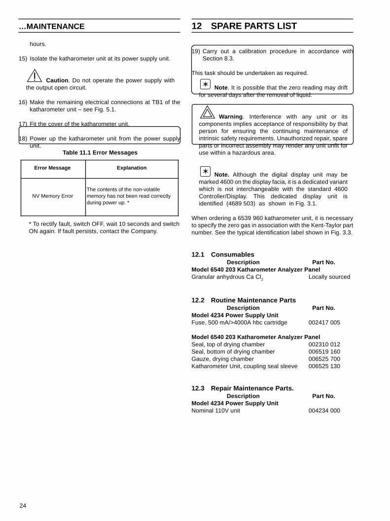
19) Carry out a calibration procedure in accordance withSection 8.3.
This task should be undertaken as required.
Note . It is possible that the zero reading may driftfor several days after the removal of liquid.
Warning . Interference with any unit or itscomponents implies acceptance of responsibility by thatperson for ensuring the continuing maintenance ofintrinsic safety requirements. Unauthorized repair, spareparts or incorrect assembly may render any unit unfit foruse within a hazardous area.
Note. Although the digital display unit may bemarked 4600 on the display facia, it is a dedicated variantwhich is not interchangeable with the standard 4600Controller/Display. This dedicated display unit isidentified (4689 503) as shown in Fig. 3.1.
When ordering a 6539 960 katharometer unit, it is necessaryto specify the zero gas in association with the Kent-Taylor partnumber. See the typical identification label shown in Fig. 3.3.
12.1 ConsumablesDescription Part No.
Model 6540 203 Katharometer Analyzer PanelGranular anhydrous Ca Cl2 Locally sourced
12.2 Routine Maintenance PartsDescription Part No.
Model 4234 Power Supply UnitFuse, 500 mA/>4000A hbc cartridge 002417 005
Model 6540 203 Katharometer Analyzer PanelSeal, top of drying chamber 002310 012Seal, bottom of drying chamber 006519 160Gauze, drying chamber 006525 700Katharometer Unit, coupling seal sleeve 006525 130
12.3 Repair Maintenance Parts.Description Part No.
Model 4234 Power Supply UnitNominal 110V unit 004234 000
…MAINTENANCE 12 SPARE PARTS LIST
* To rectify fault, switch OFF, wait 10 seconds and switchON again. If fault persists, contact the Company.
Table 11.1 Error Messages
Error Message Explanation
NV Memory ErrorThe contents of the non-volatile memory has not been read correctly during power up. *
hours.
15) Isolate the katharometer unit at its power supply unit.
Caution . Do not operate the power supply withthe output open circuit.
16) Make the remaining electrical connections at TB1 of thekatharometer unit – see Fig. 5.1.
17) Fit the cover of the katharometer unit.
18) Power up the katharometer unit from the power supplyunit.
25
13 SPECIFICATION 13 SPECIFICATION…
-0.0 -0.0
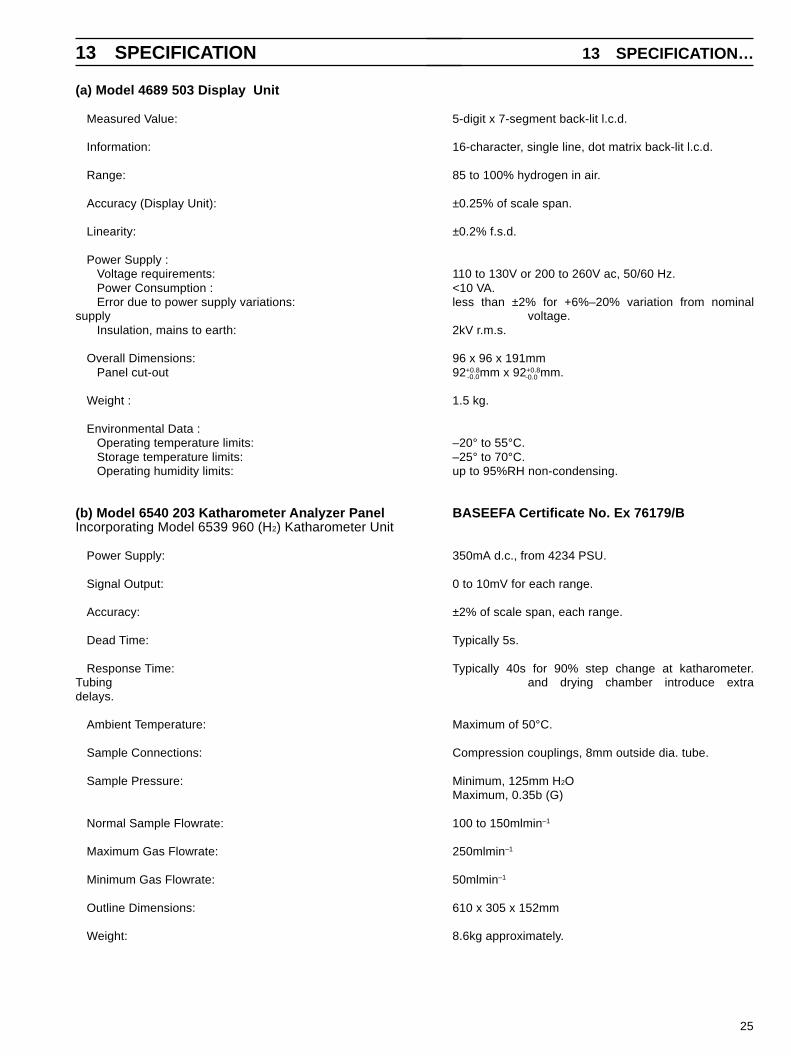
(a) Model 4689 503 Display Unit
Measured Value: 5-digit x 7-segment back-lit l.c.d.
Information: 16-character, single line, dot matrix back-lit l.c.d.
Range: 85 to 100% hydrogen in air.
Accuracy (Display Unit): ±0.25% of scale span.
Linearity: ±0.2% f.s.d.
Power Supply : Voltage requirements: 110 to 130V or 200 to 260V ac, 50/60 Hz. Power Consumption : <10 VA. Error due to power supply variations: less than ±2% for +6%–20% variation from nominal
supply voltage. Insulation, mains to earth: 2kV r.m.s.
Overall Dimensions: 96 x 96 x 191mm Panel cut-out 92+0.8mm x 92+0.8mm.
Weight : 1.5 kg.
Environmental Data : Operating temperature limits: –20° to 55°C. Storage temperature limits: –25° to 70°C. Operating humidity limits: up to 95%RH non-condensing.
(b) Model 6540 203 Katharometer Analyzer Panel BASEEFA Certificate No. Ex 76179/BIncorporating Model 6539 960 (H2) Katharometer Unit
Power Supply: 350mA d.c., from 4234 PSU.
Signal Output: 0 to 10mV for each range.
Accuracy: ±2% of scale span, each range.
Dead Time: Typically 5s.
Response Time: Typically 40s for 90% step change at katharometer.Tubing and drying chamber introduce extradelays.
Ambient Temperature: Maximum of 50°C.
Sample Connections: Compression couplings, 8mm outside dia. tube.
Sample Pressure: Minimum, 125mm H2OMaximum, 0.35b (G)
Normal Sample Flowrate: 100 to 150mlmin–1
Maximum Gas Flowrate: 250mlmin–1
Minimum Gas Flowrate: 50mlmin–1
Outline Dimensions: 610 x 305 x 152mm
Weight: 8.6kg approximately.
26
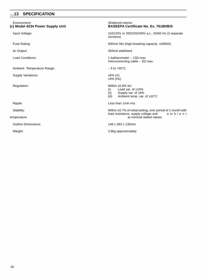
Environment: Sheltered interior.(c) Model 4234 Power Supply Unit BASEEFA Certificate No. Ex. 76180/B/S
Input Voltage: 110/120V or 200/220/240V a.c., 50/60 Hz (2 separateversions)
Fuse Rating: 500mA hbc (high breaking capacity ≥4000A)
dc Output: 350mA stabilised
Load Conditions: 1 katharometer – 13Ω max.Interconnecting cable – 2Ω max.
Ambient Temperature Range: – 5 to +50°C
Supply Variations: ±6% (V)±4% (Hz)
Regulation: Within ±0.8% for:(i) Load var. of ±15%(ii) Supply var. of ±6%(iii) Ambient temp. var. of ±10°C
Ripple: Less than 1mA rms
Stability: Within ±0.7% of initial setting, over period of 1 month withload resistance, supply voltage and a m b i e n t
temperature at nominal stated values
Outline Dimensions: 148 x 283 x 135mm
Weight: 3.8kg approximately.
…13 SPECIFICATION

27
Table A1 Test Point Values - Model 4234 Power Supply Unit
Environment:Sheltered interiorA1.1 Model 4234 Power Supply UnitTwo different power supply units are available to suit differentsupply voltages. See Spare Parts List .
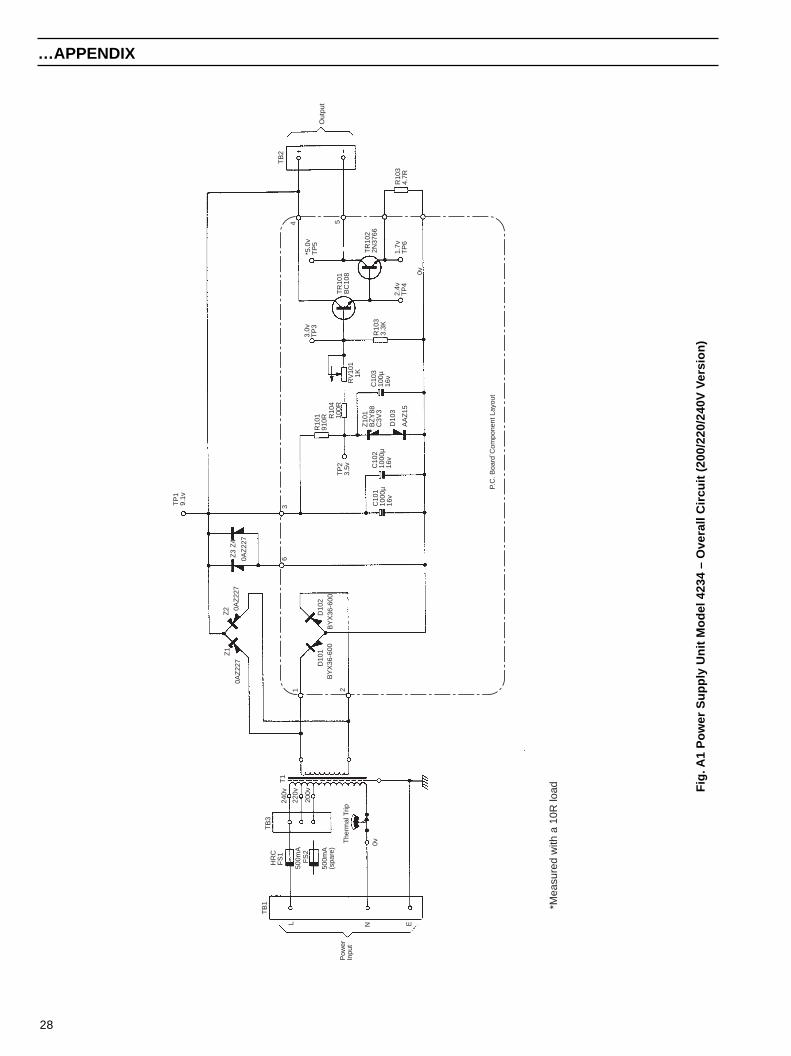
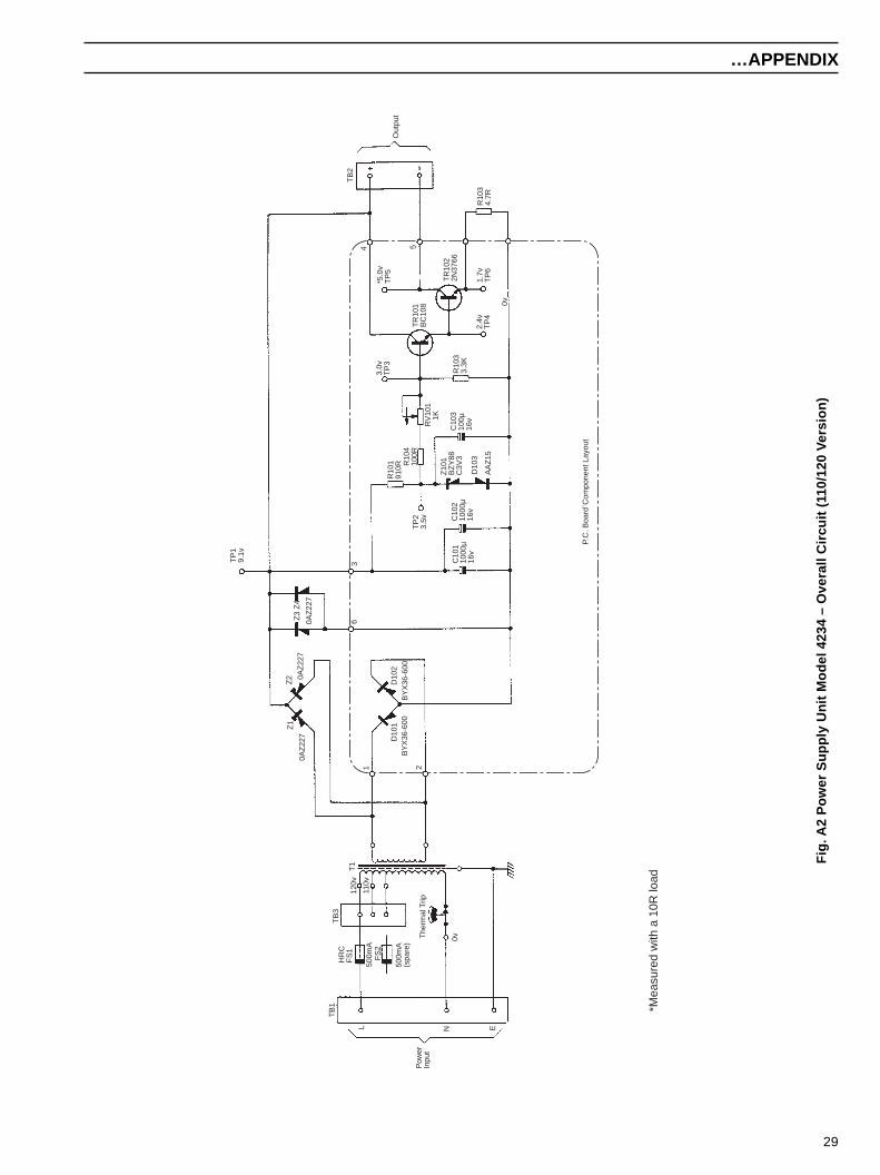
A1.1.1 Functional DescriptionA circuit diagram for each type is shown in Fig. A1 (240V),Fig. A2 (110V).
A stable supply voltage is produced across zener diodes Z3and Z4 by utilizing the forward slope resistance of zenerdiodes Z1 and Z2 in the full-wave rectifier bridge connected tothe secondary winding of transformer T1. A reference voltageis produced across C103 by zener diode Z101 in conjunctionwith R101, with diode D103 providing temperaturecompensation. This reference voltage is applied to the base ofTR101, which is used to drive the power transistor TR102 toproduce a constant current output of 350mA. The small presetpotentiometer RV101 is used to provide a fine adjustment forthe current output.
The output current is restricted by inviolate resistors whichensure that the requirements of the intrinsic safety certificationare met, even under a '2-fault' condition.
Warning . This unit is part of the certifiedintrinsically safe system, Appropriate safety precautionsmust be taken to prevent any incendive electricaldischarges in the hazardous area when carrying outmaintenance tasks.
A1.1.2 Fault Finding
Caution. Do not operate this unit without anelectrical load on the output.
If testing indicates that this unit is defective, further fault findingmay be carried out based on the typical test point values givenin Table A1. There are several test points available on the unit.Reference should be made to Figs. A1, A2 and the markings
on the circuit boards for the location of test points andcomponents.
Note. The primary winding of the transformer T1incorporates a thermal cutout device to preventoverloading under fault conditions. Sufficient time mustbe allowed for this to cool and reset after a fault hasoccurred, and before continuing further testing.
A1.1.3 Parts List
Repair Maintenance Parts
Description Part No.ResistorR101, 910R, ±2%, 0.5W, metal oxide -R102, 3k3, ±2%. 0.5W, metal oxide -R103, 4R7, ±1%, 9W, wirewound -R104, 100R, ±2%, 0.5W, metal oxide -
Variable resistorRV 101, 1k0, Spectrol Reliance, CW51 -
CapacitorC101, 1000µF, 16V, elect., Mullard 0175 15102 -C102, 1000µF, 16V, elect., Mullard 0175 15102C103, 100µF, 16V, elect., Mullard 0165 14101 -
TransistorTR101, BC 108, Mullard -TR 102, 2N 3766, Motorola -
DiodeD101, BYX 36 - 600, Mullard -D102, BYX 36 - 600, Mullard -D103, AAZ - 15, Mullard -
Zener diodeZ1, BZY93C9V1, Mullard -Z2, BZY93C9V1. Mullard -Z3, BZY93C9V1, Mullard -Z4, BZY93C9V1, Mullard -Z101, BZY88C3V3, Mullard -
FuseFS1, 500mA, hbc cartridge, Belling Lee L693 -
TransformerT1, 110 - 120V primary 4234 130T1, 200 - 220 - 240V primary 4234 140
Test PointVoltage
VForm Conditions
TP1 9.1 d.c. With respect to 0V
TP2 3.5 d.c. With respect to 0V
TP3 3.0 d.c. With respect to 0V
TP4 2.4 d.c. With respect to 0V
TP5 5.0 d.c.With respect to 0V using
10Ω dummy load
TP6 1.7 d.c. With respect to 0V
T1 9.1 a.c. At secondary
APPENDIX APPENDIX…
28
Fig
. A1
Pow
er S
uppl
y U
nit M
odel
423
4 –
Ove
rall
Circ
uit (
200/
220/
240V
Ver
sion
)
Pow
erIn
put
Out
put
TB
1H
RC
FS
1
500m
A22
0v
240v
200v
FS
2
500m
A(s
pare
)
TB
3
L N E
The
rmal
Trip
T1
1 2
Z1
0AZ
227
Z2 0A
Z22
7
D10
1D
102
BY
X36
-600
BY
X36
-600
Z3
Z4
0AZ
227
63T
P1
9.1v
C10
110
00µ
16v
C10
210
00µ
16v
TP
23.
5v
R10
191
0RR
104
100R
Z10
1B
ZY
88C
3V3
D10
3
AA
Z15
RV
101
1K
C10
310
0µ16
v
R10
33.
3K
3.0v
TP
3
TR
101
BC
108
2.4v
TP
4
TR
102
2N37
66
1.7v
TP
6
0v
R10
34.
7R
TB
2
4 5
P.C
. Boa
rd`C
ompo
nent
Lay
out
*Mea
sure
d w
ith a
10R
load
0v
*5.0
vT
P5
…APPENDIX
29
Fig
. A2
Pow
er S
uppl
y U
nit M
odel
423
4 –
Ove
rall
Circ
uit (
110/
120
Ver
sion
)
Pow
erIn
put
Out
put
TB
1H
RC
FS
1
500m
A11
0v
120v
FS
2
500m
A(s
pare
)
TB
3
L N E
The
rmal
Trip
T1
1 2
Z1
0AZ
227
Z2 0A
Z22
7
D10
1D
102
BY
X36
-600
BY
X36
-600
Z3
Z4
0AZ
227
63T
P1
9.1v
C10
110
00µ
16v
C10
210
00µ
16v
TP
23.
5v
R10
191
0RR
104
100R
Z10
1B
ZY
88C
3V3
D10
3
AA
Z15
RV
101
1K
C10
310
0µ16
v
R10
33.
3K
3.0v
TP
3
TR
101
BC
108
2.4v
TP
4
TR
102
2N37
66
1.7v
TP
6
0v
R10
34.
7R
TB
2
4 5
P.C
. Boa
rd`C
ompo
nent
Lay
out
*Mea
sure
d w
ith a
10R
load
0v
*5.0
vT
P5
…APPENDIX

30
NOTES

31
NOTES

32
NOTES

PRODUCTS & CUSTOMER SUPPORT
A Comprehensive Instrumentation Range
Analytical Instrumentation• Transmitters
On-line pH, conductivity, and dissolved oxygentransmitters and associated sensing systems.
• SensorspH, redox, selective ion, conductivity and dissolvedoxygen.
• Laboratory InstrumentationpH and dissolved oxygen meters and associatedsensors.
• Water AnalyzersFor water quality monitoring in environmental, powergeneration and general industrial applications including:pH, conductivity, ammonia, nitrate, phosphate, silica,sodium, chloride, fluoride, dissolved oxygen andhydrazine.
• Gas AnalyzersZirconia, paramagnetic, infrared, thermal conductivity.
Controllers & Recorders• Controllers
Digital display, electronic, pneumatic. Discrete single-loop and multi-loop controllers which can be linked to acommon display station, process computer or personalcomputer.
• RecordersCircular and strip-chart types (single and multi-point) fortemperature, pressure, flow and many other processmeasurements.
Electronic Transmitters• Smart & Analog Transmitters
For draft, differential, gauge and absolute pressuremeasurement. Also, liquid level and temperature
• I to P Converters and Field Indicators
Flow Metering• Magnetic Flowmeters
Electromagnetic, insertion type probes and watermeters.
• Turbine Flowmeters
• Wedge Flow Elements
• Mass Flow MetersTransmitters, sensors, controllers and batch/displayunits.
Level Control• Submersible, Capacitance & Conductivity.
Pneumatic Instrumentation• Transmitters
• Indicating Controllers
• Recording Controllers
Customer Support
ABB Kent-Taylor provides a comprehensive after salesservice via a Worldwide Service Organization. Contact one ofthe following offices for details on your nearest Service andRepair Centre.
United KingdomABB Kent-Taylor LimitedTel: +44 (0)1480 470781Fax: +44 (0)1480 470787
United States of AmericaABB Kent-Taylor Inc.Tel: +1 716 2926050Fax: +1 716 2736207
ItalyABB Kent-Taylor SpATel: +39 (0) 344 58111Fax: +39 (0) 344 56278
Client Warranty
Prior to installation, the equipment referred to in this manualmust be stored in a clean, dry environment, in accordance withthe Company's published specification. Periodic checks must bemade on the equipment's condition.
In the event of a failure under warranty, the followingdocumentation must be provided as substantiation:
1. A listing evidencing process operation and alarm logs at timeof failure.
2. Copies of operating and maintenance records relating to thealleged faulty unit.

The Company's policy is one of continuous productimprovement and the right is reserved to modify theinformation contained herein without notice.
© December 1995 ABB Kent-Taylor Printed in U.K.
ABB Kent-Taylor Ltd.St. Neots,Cambs.England, PE19 3EUTel: (01480) 475321Fax: (01480) 217948
ABB Kent-Taylor Inc.PO Box 20550, RochesterNew York 14602-0550USATel: (716) 292 6050Fax: (716) 273 6207
ABB Kent-Taylor SpA22016 LennoComoItalyTel: (0344) 58111Fax: (0344) 56278
IM/6
5535
03Is
sue
2
ABB Kent-Taylor Ltd.Analytical & Flow GroupStonehouse, Glos.England, GL10 3TATel: (01453) 826661Fax: (01453) 826358