aas 13-492 automated design of propellant-optimal, …
TRANSCRIPT

AAS 13-492
AUTOMATED DESIGN OF PROPELLANT-OPTIMAL, END-TO-END,LOW-THRUST TRAJECTORIES FOR TROJAN ASTEROID TOURS
Jeffrey Stuart∗, Kathleen Howell†, and Roby Wilson‡
The Sun-Jupiter Trojan asteroids are celestial bodies of great scientific interest aswell as potential resources offering mineral resources for long-term human ex-ploration of the solar system. Previous investigations under this project have ad-dressed the automated design of tours within the asteroid swarm. The current au-tomation scheme is now expanded by incorporating options for a complete trajec-tory design approach from Earth departure through a tour of the Trojan asteroids.Computational aspects of the design procedure are automated such that end-to-endtrajectories are generated with a minimum of human interaction after key elementsassociated with a proposed mission concept are specified.
INTRODUCTION
Near Earth Objects (NEOs) are currently under consideration for manned sample return mis-sions,1 while a recent NASA feasibility assessment concludes that a mission to the Trojan asteroidscan be accomplished at a medium class, New Frontiers level.2 Tour concepts within asteroid swarmsallow for a broad sampling of interesting target bodies either for scientific investigation or as poten-tial resources to support deep-space human missions. However, the multitude of asteroids within theswarms necessitates the use of automated design algorithms if a large number of potential missionoptions are to be surveyed. Previously, a process to automatically and rapidly generate sample tourswithin the Sun-Jupiter L4 Trojan asteroid swarm with a minimum of human interaction has beendeveloped.3 This investigation extends the automated algorithm to include a variety of electricalpower sources for the low-thrust propulsion system. The proposed tour creation strategy is not spe-cific to the problem of asteroid missions and, therefore, the low-thrust tour design concept is readilyapplied to a diverse range of prospective mission scenarios.
High-efficiency, low-thrust propulsion systems are particularly attractive for missions to the Sun-Jupiter equilateral equilibrium points because of the relatively stable natural gravitational dynamicsin these regions. Propellant-optimal, low-thrust trajectories, realized by constant specific implusesystems in nonlinear dynamical regimes, typically require coasting arcs and the careful balancingof engine capability with transfer time. The inclusion of additional coasting arcs requires engineshut-downs and restarts that may be operationally inefficient and generally infeasible. Therefore,
∗Graduate Student, Purdue University, School of Aeronautics and Astronautics, 701 W. Stadium Ave., West Lafayette, IN,47906, (765) 620-4342, [email protected].†Hsu Lo Professor of Aeronautical and Astronautical Engineering, Purdue University, School of Aeronautics and Astro-nautics, 701 W. Stadium Ave., West Lafayette, IN, 47906, (765) 494-5786, [email protected].‡Supervisor, Inner Planet Missions Analysis Group, Mission Design and Navigation Section, Jet PropulsionLaboratory, California Institute of Technology, 4800 Oak Grove Dr., Pasadena, CA 91109, (818) 393-5301,[email protected].
1

a variable specific impulse (VSI) engine that varies the optimal thrust magnitude is selected tosimplify the generation of rendezvous solutions.4 As a consequence, no coasting arcs are requiredfor rendezvous and the initial generation of optimal trajectories is less restrictive in terms of thrustduration. Examples of VSI engines include the Variable Specific Impulse Magnetoplasma Rocket(VASIMR) currently under development by the Ad Astra Rocket Company5 and the Electron andIon Cyclotron Resonance (EICR) Plasma Propulsion Systems at Kyushu University in Japan.6
In general, the computation of locally fuel-optimal trajectories is posed as an optimal controlproblem. The possible formulations to solve the problem include a low-dimension but less flexibleindirect approach using optimal control theory7, 8, 9 or a higher-dimension but more robust directscheme.10, 11, 12 A combination of an indirect and a direct method is termed a hybrid optimizationalgorithm and exploits the relative benefits of both local optimization strategies. For this inves-tigation, the Euler-Lagrange Theorem13 offers conditions for optimal engine operation while theoptimization packages SNOPT14 and fmincon minimize propellant costs. Relatively short times-of-flight (compared to long-duration spiral trajectories), as well as continuation methods, furtherincrease the solution stability.
Previous investigations have resulted in a scheme that generates tour sequences within the asteroidswarm, as well as an outbound, or interplanetary, leg that departs the Earth and terminates with arendezvous at the first asteroid in the sequence.3 For the interplanetary transfer arc to the swarm, alow-thrust propulsion system must be augmented to produce a transfer that can be accomplished in areasonable length of time. Therefore, a V∞ at Earth departure, delivered by conventional high-thrustchemical engines, any number of planetary fly-bys, or some combination of such external optionsto gain energy are incorporated. In this application, the only thrust along the outbound arc afterEarth departure is delivered by the low-thrust system. This combination of low-thrust and departureV∞ is a specific example of hybrid propulsion, i.e., the blending of various propulsion methods. Byspecifying that the spacecraft “arrival” condition matches the initial state along the tour path withinthe swarm, the two independent segments are joined into an end-to-end baseline design offeringcost and timing estimates for a Trojan asteroid tour.
In this investigation, the effect of the electrical power source is examined within the context ofthe trajectory design and optimization procedures as well as the resulting propellant consumptionand engine operation histories. Three types of electrical power sources are compared:
1. constant power Nuclear Electric Propulsion, or NEP, systems,
2. varying power Solar Electric Propulsion, or SEP, thrusters,
3. hybrid constant/varying power Power-Limited SEP, or PLS, engines.
Constant power systems typically employ an on-board source, such as radioisotope thermoelectricgenerators (RTGs), to deliver a consistent, but limited, supply of electrical power. In contrast, SEPsystems use photons emitted by the Sun, and collected by solar cells affixed to the spacecraft, toprovide electrical power. However, a potential concern for SEP spacecraft involves the Sun as apower source, i.e., (i) photon density is inversely proportional to the square of the distance from theSun and (ii) extended periods of shadow must be avoided along the baseline path and incorporated inany guidance algorithm. A further concern for any low-thrust propulsion system is the usual upperbound on engine power for safe operation or a peak engine efficiency power level. In either case,a limit exists upon the maximum power available to the engine, even though the solar panels on a
2

SEP spacecraft may collect more than sufficient electricity to exceed this bound. Thus, a power-limited SEP thruster is also investigated, where this engine type is modeled as a hybrid system ofconstant- and varying-power engines. Three distinct low-thrust propulsion scenarios offer a varietyof challenges and opportunities, especially when implemented in an overall automated trajectorygeneration procedure.
SYSTEM MODELS
Two key steps are initially necessary to successfully formulate the rendezvous problem, namelythe definition of the physical environment for modeling of the system dynamics and the constructionof the initial and target state vectors. The model for the unpowered spacecraft dynamics is inde-pendent of the low-thrust and optimization strategies and is, therefore, adjusted to introduce variouslevels of model fidelity.
Circular Restricted Three-Body Problem
The dynamics are initially modeled in terms of the Circular Restricted Three Body Problem(CR3BP) with the Sun as one primary and Jupiter as the second. Note that, even though the space-craft departs from the Earth and a V∞ relative to the Earth is evaluated, Earth gravity is not includedin this model. The equations of motion are formulated within the context of a rotating referenceframe where x is directed from the Sun to Jupiter, z is normal to the orbital plane of the primariesand parallel to orbital angular momentum, and y completes the right-handed set. The origin ofthe coordinate system is the Sun-Jupiter barycenter. Incorporated into the forces that influence thevehicle motion within this system are terms that arise from the thrusting of a Variable Specific Im-pulse (VSI) engine. The system of equations are nondimensionalized to aid numerical integrationefficiency: computational results are converted to dimensional quantities by the proper use of thecharacteristic quantities and spacecraft parameter values. The characteristic quantities are defined asthe Sun-Jupiter distance, the mass of the primaries, the characteristic time, and the initial spacecraftmass. The spacecraft state vector is then defined as:
χ =
rvm
(1)
where r is the position vector relative to the barycenter, v is the velocity vector, i.e., the derivativeof r, as viewed by a rotating observer, and m is the instantaneous mass of the spacecraft. Note thatbold type indicates vector quantities. The equations of motion are then derived with the result:
χ =
rvm
=
v
fn(r,v) + Tmu
−T 2
2P
(2)
where T is thrust magnitude, P is engine power, u is a unit vector defining the thrust direction, andfn represents the natural acceleration of the spacecraft. Furthermore, denote the six-dimensionalvector that includes the scalar componenets of the position r and velocity v states by the vector x,where x =
[x y z x y z
]T . The scalar elements of fn are then expressed in terms of the rotating
3

frame as:
fn =
2y + x− (1−µ)(x+µ)
d31− µ(x+µ−1)
d32
−2x+ y − (1−µ)yd31− µy
d32
− (1−µ)zd31− µz
d32
(3)
where d1 and d2 are the distances to the vehicle from the Sun and Jupiter, respectively, that is
d1 =√
(x+ µ)2 + y2 + z2 (4)
d2 =√
(x+ µ− 1)2 + y2 + z2. (5)
The mass parameter µ is
µ =MJ
MS +MJ(6)
where MS and MJ are the masses of the Sun and Jupiter, respectively. The power P is defined as ascalar value between zero and a maximum available power level specified by the engine model andthe operating conditions, such that
0 ≤ P ≤ Pmax. (7)
For this investigation, the value of Pmax is specified in terms of a reference power level Pref forNEP and SEP systems while an engine power limit Plim is employed to further define a PLS system.Then, the engine thrust T is evaluated via
T =2P
Ispg0(8)
where Isp is the engine specific impulse and g0 = 9.80665 m/s2, the gravitational acceleration atthe surface of the Earth. Further information on the system and spacecraft parameters is availablein Table 1.
Table 1. System and spacecraft parameter values.
Quantity Value
Solar mass (MS), kg 1.9891×1030
Jupiter mass (MJ ), kg 1.8986×1027
Gravitational Constant (G), km3
kg·sec2 6.67428×10⁻²⁰
Mass parameter (µ) 9.53816×10⁻⁴
Sun-Jupiter distance (l∗), km 7.78412×10⁸
Characteristic Time (t∗), sec 5.95911×10⁷
Characteristic Time (t∗d), days 6.89712×10²
Reference spacecraft mass (mr), kg 500
Reference engine power (Pref ), kW 1.0
Engine power limit (Plim), kW 4.0
4

Point-Mass Ephemeris Model and Relative Equations of Motion
While the CR3BP serves as a powerful tool for initial analysis, higher-fidelity models are requiredfor more detailed and accurate investigation. A more accurate model for point masses moving underthe influence of point-mass gravity fields is provided by the relative vector equation of motion for aparticle i moving with respect to a central body q:
rqi +G(mi +mq)
r3qirqi = G
n∑j=1j 6=i,q
mj
(rijr3ij− rqjr3qj
)(9)
where additional bodies are denoted by the subscript j. The positions and velocities of celestial bod-ies are available from the Jet Propulsion Laboratory’s HORIZONS system.15 The relative positionvector rij is defined
rij = rqj − rqi (10)
where all positions are known relative to the central body q. Therefore, the natural dynamics of thespacecraft in an inertial frame are mathematically modeled as
fn(t, rqi) = −G(mi +mq)
r3qirqi +G
n∑j=1j 6=i,q
mj
(rijr3ij− rqjr3qj
)(11)
where the system is no longer time invariant. Since motion within the asteroid swarm is relativelydistant from most perturbing bodies, only the Sun and Jupiter are incorporated in the ephemerismodel for this preliminary investigation. Additional bodies can be readily added and the numberdoes not alter the low-thrust engine model or the implementation of the optimization algorithm.
Initial and Target States
The computation of rendezvous arcs requires the definition of an initial state from which thespacecraft departs whenever a thrust segment is initiated and a target state that serves as a matchingcondition for the spacecraft state vector upon arrival in the vicinity of the swarm. This definitionis accomplished by specifying the initial state xI to be the position and velocity of a specifiedasteroid (or Earth, for the Earth to asteroid arc) that is considered the departure body for a particularrendezvous segment. Likewise, the target state xT is the position and velocity of the desired arrivalbody. In the ephemeris point-mass model, the states corresponding to specific celestial bodies at agiven epoch are determined by interpolation of the HORIZONS data. For the simplified model usedin the automated tour design scheme, however, an equivalent continuous path for the appropriatecelestial body is determined, where the motion satisfies the natural dynamics in the Sun-JupiterCR3BP. Accordingly, a set of reference nodes are extracted from the HORIZONS data, transformedto the Sun-Jupiter rotating frame, and supplied as the initial guess for a multiple shooting correctionsprocess where continuity is specified for all interior points.16 In this corrections scheme, the nodesare allowed to vary without constraint, assuming that the resulting solution offers a continuous pathfor the asteroid motion. Figure 1 illustrates one such conversion, with the original HORIZONSdata represented by a dashed line and the reconstructed continuous CR3BP trajectory plotted as thesolid line. Motion for all 10 asteroids, as well as the Earth, is transitioned to the CR3BP. Oncea tour trajectory is determined within the context of the CR3BP, the results are transitioned to thepoint-mass ephemeris model to restore the true positions of the asteroids and the Earth.
5

Figure 1. Path of asteroid 1143 Odysseus from Oct. 3, 2021 to Oct. 3, 2061 in Sun-Jupiter rotating frame from ephemeris data (dashed) and under CR3BP dynamics(solid)
TRAJECTORY OPTIMIZATION
A local hybrid optimization scheme is proposed wherein indirect procedures are combined withdirect methods to retain low-dimensionality and, therefore, computational efficiency, while increas-ing the robustness of the convergence characteristics. The application of techniques from the cal-culus of variations supplies conditions on optimal operation of the engine while requiring onlythe solution for a set of co-states. In addition to reducing the number of function evaluations periteration, this indirect approach also ensures a smooth and continuous control history while notrestricting engine operation time histories to an assumed form. A spacecraft mass objective func-tion is locally optimized using a gradient-based procedure, removing a requirement to derive andemploy the sensitive transversality conditions common in indirect methods. Global and heuristicalgorithms, though not addressed in this analysis, can also be used to optimize fuel performance.
Three distinct low-thrust engine types are examined in this investigation: constant power sys-tems (e.g., NEP), varying power thrusters (e.g., SEP), and hybrid constant- and varying-power en-gines (e.g., PLS). While the underlying natural dynamics are unaltered, the variation in the powersource affects the conditions for optimal engine operation. Accordingly, for the constant-power andvarying-power scenarios, the rendezvous problem is first posed indirectly using the calculus of vari-ations for a formulation as a two-point boundary value problem (2PBVP). The engine operationalstates are then determined from the Euler-Lagrange equations. The two distinct sets of operatingconditions and differential equations arising from the constant- and varying-power thrusters are thencombined, with appropriate switching conditions, for trajectories generated using a PLS engine. Inall of the cases, the thrust duration TD must be pre-specified when a VSI engine is employed. Ifno limit is placed on either the thrust duration or the mass consumption, the optimization processdrives TD and Isp to infinity to produce zero propellant mass.
6

Indirect Optimization of Constant Power Thrust Arcs
When the on-board propulsion system is powered by a self-contained power source, as is the casewith a NEP engine, the maximum engine power Pmax is assumed to be a constant value over theduration of the mission. For all NEP trajectories in this investigation, the maximum engine poweris specified to be Pmax = Pref = 1 kW unless otherwise noted. To fully define the optimizationproblem, the performance index and the boundary conditions must also be specified. To arriveat the target asteroid with the maximum final spacecraft mass for a specified thrust duration, theperformance index J is defined
max J = mf . (12)
The boundary conditions and the Hamiltonian are adjoined to the performance index, such thatEq. (12) is expanded to become the Bolza function
max J ′ = mf + νT0 ψ0 + νTf ψf +
∫ tf
t0
[H − λT χ]dt (13)
where H is the problem Hamiltonian, λ is a co-state vector, the terms ψ are vectors comprised ofboundary conditions, and the vector terms involving ν are Lagrange multipliers corresponding tothe boundary conditions. The co-state vector is then
λ =
λr
λv
λm
(14)
where λr and λv are three-dimensional vectors comprised of the position and velocity co-states,respectively, and the scalar λm is the mass co-state. The initial and final vector boundary conditionsare
ψ0 = xI − xI(τ0) = 0 (15)
andψf = xT − xT (τ0 + TD) = 0 (16)
where the subscripts I and T indicate the states associated with the current asteroid and the targetasteroid, respectively. Equation (15) is implicitly satisfied by defining xI as the state along thecurrent asteroid trajectory as defined by the parameter τ0. The final, or target, boundary conditionsin Eq. (16) are satisfied by solving the boundary value problem.
The calculus of variations is employed to define several properties of the 2PBVP and to acquirethe derivatives of the co-states. The problem Hamiltonian is
H = λT χ = λTr v + λTv
[fn(t, r,v) +
T
mu
]− λm
T 2
2P(17)
where the value of H is constant over the trajectory for the time invariant CR3BP. For the timevarying ephemeris model, H is no longer a constant value. The optimal control strategy emerges bymaximizing the Hamiltonian with respect to the controls T , P , and u such that
P = Pmax (18)
T =λvPmax
λmm(19)
u =λv
λv(20)
7

where λv=||λv||. Given these control expressions, the Hamiltonian is reformulated and Eq. (17) isrewritten as
H = λTr v + λTvfn + S · T (21)
where S is the switching function
S =λvm− λmT
2Pmax. (22)
The Euler-Lagrange conditions for optimality modify the performance index in Eq. (13). With thereformulated Hamiltonian, that is, Eq. (21), the following equations of motion for the co-statesemerge
λ = −(∂H
∂χ
)T=
−λTv
(∂fn
∂r
)−λTr − λTv
(∂fn
∂v
)λv
Tm2
(23)
where the initial state for λm is set equal to unity to reduce the number of variables to be determined.Note that: (a) a similar procedure to minimize the initial mass for a given target mass results inidentical conditions for engine operation, and (b) the differential equations for the co-states do notchange form based upon the underlying natural dynamics; thus, ∂fn
∂r and ∂fn
∂v are freely substitutedwhen using models of varying fidelity.
Indirect Optimization of Varying Power Thrust Arcs
The development of the operational conditions for a varying engine power, e.g., SEP, systemproceeds similarly to the indirect method for NEP thrusters. In contrast, however, the maximumavailable engine power is now determined via
Pmax =Pref
d2s(24)
where ds is the nondimensional distance between the spacecraft and the Sun. Note that ds = d1 inthe CR3BP and ds = ‖rqi‖ in the ephemeris model. Under this power law, the spacecraft possessesa nominal operating power of 1 kW while in the vicinity of the L4 libration point but the availableengine power rapidly rises as the spacecraft approaches the inner solar system. For a pure SEPsystem, the available engine power is not constrained by any upper or lower limits.
The objective function and constraints for a SEP system are the same as for NEP engines, soEqs. (12)-(16) are unchanged in the definition of the 2PBVP. Recalling from Eq. (18) that the mostefficient engine operation occurs at the maximum available power level, the new problem Hamilto-nian is then
H = λT χ = λTr v + λTv
[fn(t, r,v) +
T
mu
]− λm
T 2d2s2Pref
. (25)
As before, maximizing the Hamiltonian produces the primer vector in Eq. (20) and the thrust mag-nitude control
T =λvPref
λmmd2s(26)
while the Euler-Lagrange conditions yield the co-state equations of motion
λ = −(∂H
∂χ
)T=
−λTv
(∂fn
∂r
)+ λm
T 2
Prefds
−λTr − λTv(∂fn
∂v
)λv
Tm2
(27)
8

where ds is the distance vector from the Sun to the spacecraft (ds = d1 and ds = rqi for the CR3BPand ephemeris models, respectively). Consistent with a constant-power thrust arc, the engine oper-ating conditions and the differential equations are unchanged if the initial mass is minimized or ifdiffering models of the natural dynamics are incorporated.
Hybrid Optimization and Hybrid Propulsion
The design process for the overall mission trajectory is comprised of two parts. Tour creationwithin the asteroid swarm is first accomplished; computation of the individual rendezvous arcs isan integral component. The second step is then the generation of the interplanetary arc from theEarth to the asteroid swarm. This split is used advantageously to isolate and address challengesassociated with each of the two components without affecting the design and computation of theopposite element. However, the end conditions along the outbound segment must be carefullyblended with the initial conditions corresponding to any specifice rendezvous sequence. Therefore,it is natural to pose the propellant minimization problem differently for the two components, i.e., theoutbound segment and the tour phase. So, for reference rendezvous arcs within the swarm, the initialspacecraft mass is specified as the reference mass from Table 1, i.e., m0 = mr. The optimizationpackage SNOPT is then employed to maximize the final mass mf , with the additional nonlinearconstraints specified by Eqs. (15) and (16). Note that the same initial condition, m0 = mr, is usedfor all baseline asteroid-to-asteroid arcs generated in the CR3BP.
As previously stated, the Earth departure leg greatly benefits from the inclusion of a hybridpropulsion scheme assuming the option of an initial departure velocity. Propellant mass is optimizedby targeting a final spacecraft mass of mf = mr while using SNOPT to minimize the spacecraftmass at Earth departure m0. However, the inclusion of a realtive departure velocity invalidates theinitial boundary condition as posed in Eq. (15). Position continuity must be maintained, but velocityis now constrained, i.e., √
∆vI ·∆vI − V∞ = 0 (28)
where ∆vI = vI−v⊕(τ0), such that vI is the spacecraft initial velocity and v⊕(τ0) is defined as thevelocity of Earth at spacecraft departure. The departure V∞ is selected based upon the capabilitiesof a chemical booster stage or hyperbolic velocity after an Earth flyby. Thus, for the interplanetaryleg, SNOPT minimizes the initial spacecraft mass m0 subject to the constraints in Eqs. (16) and(28) as well as position continuity with the Earth at the initial departure epoch.
AUTOMATED TOUR CREATION
A mission to the vicinity of the Sun-Jupiter “Greek” or “Trojan” asteroid families will almostcertainly entail rendezvous with and the observation of multiple objects. Recall that the asteroidtour is determined prior to the generation of an Earth-to-asteroid outbound segment. A previousinvestigation as part of this project proposed a strategy to rapidly and automatically generate a largenumber of candidate asteroid tours satisfying a set of constraints.3 This trajectory evaluation schemecombines CR3BP dynamics and a NEP system and, therefore, yields only approximate propellantcosts. The asteroid swarm rendezvous sequences in the current investigation are constructed usingthe preliminary design scheme and further refined by adjusting the dynamical fidelity and propulsionsystem parameters to realize more accurate timing and propellant requirements.
9

Outbound Leg Generation
For a specific Trojan tour of interest, an Earth-to-swarm segment must be included such that thespacecraft rendezvous with the first asteroid in the tour occurs prior to the asteroid arrival epoch.As previously stated, this arc is enabled by the use of a hybrid propulsion scheme where an initialEarth-departure V∞ is pre-specified. Recall that the objective of the optimization procedure alongthis leg is the minimization of the initial spacecraft mass subject to the constraint that the massupon asteroid arrival equals 500 kg. This phase of the trajectory design process is also automatedby creating a library of pre-generated trajectory arcs using CR3BP dynamics and an NEP engine.So, point solutions for locally optimal rendezvous arcs between Earth and each of the 10 sampleasteriods are computed where the departure epoch τd occurs within the year 2018 and the spacecraftarrives in the vicinity of the asteroid swarm 3.5 years later in 2021. Thereafter, for any specific tour,the pre-computed departure epoch is adjusted by a integer multiple of the Earth-Jupiter synodicperiod, that is, 398.88 days, such that the spacecraft arrives at the initial asteroid only a short timein advance of the selected starting epoch for the asteroid tour.
The outbound leg effected using a power-limited SEP system offers a challenge, that is, the enginemodel switches from a constant-power regime defined by the fixed maximum engine power to avarying-power domain where the Sun distance determines the available power. In this investigation,the switch between thrust regimes is accomplished by introducing an intermediate patch point alongthe thrust arc, where the node is defined by the state vector χs and co-state vector λs. Prior to theswitch point, the spacecraft engine operates with constant power Pmax = Plim while beyond theswitch point, the varying power is determined by Pmax = Pref
d2s, with the appropriate control laws
and co-state equations of motion. However, this switch must occur when the power available fromthe Sun matches the limit on maximum engine power. Accordingly, the constraint
Pref
d2s− Plim = 0 (29)
is incorporated when generating trajectories using a PLS system. Additional constraints on thePLS-enabled trajectory include
tc + tv − TDout = 0 (30)
and, for trajectories using ephemeris dynamical models, an additional timing constraint is
τs − τd − tc = 0 (31)
where tc is the time spent thrusting under constant power, tv is the duration of time under varyingpower, TDout the total thrust interval on the outbound leg, τs represents the switch epoch, and τdcorresponds to the epoch at Earth departure. Continuity in the state vector is ensured by
χts − χs = 0 (32)
where χts corresponds to the spacecraft state vector at the end of the constant-power thrust arcand χs is the initial seven-dimensional state on the varying-power segment. During preliminaryoptimization runs, no restriction was placed on the continuity involving the co-state vector λs,however, the naturally emerging optimal solution resulted in co-state continuity across the two thrustdomains. Accordingly, the constraint
λts − λs = 0 (33)
10
is also included for PLS outbound legs, where the addition of this constraint also allows improvedconvergence of the numerical optimization process. This result indicates the more straightforwardimplementation, that is, removing the switching node and, alternately, constructing a set of equa-tions of motion wherein the switch in engine power domain is an automatic function of the space-craft position.
Scaling Results
A convenient method of generating initial guesses for the optimization process is scaling of theresults of pre-existing solutions. In this investigation, the initial conditions for the rendezvous arcsthat are computed in the CR3BP and employing a NEP thruster are scaled to improve convergencein the delivery of a locally optimal solution. The following set of approximate relationships are usedwhen the engine operating power is altered, i.e.,
mc2 ≈P1
P2mc1 (34)
λ2 ≈P1
P2λ1 (35)
where mc is the mass consumed along the thrust arc, mc = m0 −mf . In contrast, the relationships
mc2 ≈(m0,2
m0,1
)2
mc1 (36)
λ2 ≈m2
m1λ1 (37)
are employed when altering the spacecraft mass. These two sets of scaling equations are blendedwhen both the spacecraft mass and the engine power are simultaneously modified. In additionto the construction of initial guesses, the scaling relationships are useful for rapidly examininga large variety of mission scenarios without the requirement to fully optimize the correspondingtrajectories.
Higher-Fidelity Models
Transitioning any solution or design concept to an ephemeris model is a key step for validationof the results. Given a possible asteroid tour mission, the cost as well as timing estimates andengine operation histories are obtained using a corrections algorithm in the point-mass ephemerismodel. For the tour within the swarm, accurate propellant costs are determined by incorporatingthe propellant consumed along previous thrust arcs, rather than assuming each thrust arc to beindependent. For example, after arrival in the swarm, the first rendezvous arc between asteroidsconsumes propellant mass such that thel spacecraft mass is less than 500 kg at the initiation ofthe second thrust arc. Accordingly, the optimization problem for the second asteroid-to-asteroidrendezvous arc possesses an ‘initial’ spacecraft mass equal to the arrival mass at the end of theprevious rendezvous segment. The propellant usage computation then continues throughout the tourin the swarm. The spacecraft mass at swarm arrival is still specified to be 500 kg and, therefore, theEarth-to-asteroid arc still targets an arrival mass of 500 kg. For this investigation, only the gravityof the Sun and Jupiter are incorporated in the point-mass ephemeris model; the gravitational effectof other celestial bodies, e.g., the Earth and Mars, are assumed to be negligible, even along theoutbound leg.
11

SAMPLE ASTEROID TOUR TRAJECTORY: 1143 ODYSSEUS
A sample asteroid tour trajectory is examined, where the spacecraft path includes a rendezvouswith each of the three asteroids 1143 Odysseus, 5652 Amphimachus, and 659 Nestor in sequence. Abaseline set of thrust and coast arcs is constructed within the context of the spatial CR3BP using theautomated tour selection scheme,3 where the spacecraft departs the Earth in 2022 and continues tooperated over a mission lifetime of 10 years. The reference solution is then transitioned to three end-to-end trajectories in the ephemeris model, where each trajectory is defined in terms of the enginemodel, i.e., NEP, SEP, or PLS. In all cases, however, the spacecraft is constrained to an Earth-departure excess velocity of V∞ = 7.5 km/sec and is specfied to rendezvous with 1143 Odysseusprecisely 3.5 years after departing the Earth.
The three mission scenarios are analyzed in terms of propellant consumption, mission timing,and the equivalent ∆V costs associated with the thrust arcs. The estimated end-to-end costs, as wellas departure and arrival time histories, are summarized in Tables 2 and 3. Note that all propulsionsystems deliver approximately the same final spacecraft mass. However, each mission scenarioentails a different Earth departure mass, where the NEP system requires the most propellant, thepure SEP engine the least, and the hybrid PLS thruster consumes slightly more propellant than theSEP. As is apparent in Table 3, all potential tours possess roughly equivalent departure and arrivalepochs and, accordingly, thrust and coast durations, with epochs varying on the order of days or afew weeks. The SEP and PLS trajectories are nearly equivalent within the asteroid swarm itself, asexpected since both are operating as varying-power systems during this phase of the mission. Theequivalent ∆V cost for each thrust segment, is computed via the definition
∆V =
∫ t1
t0
T
mdt. (38)
The results appear in Table 4. Because all three mission scenarios include a nominal engine op-erating power equal to 1 kW while in the L4 region, the asteroid-to-asteroid thrust arcs generatea similar amount of ∆V regardless of engine type. In contrast, the ∆V s for the outbound legsvary significantly between the engine types, where the SEP system delivers the most ∆V , the NEPthruster provides the least, and the PLS engine generates an equivalent ∆V that is approximatelythe average of the NEP and SEP values.
Table 2. Spacecraft propellant budget for 10-year mission with tour of 3 asteroids
ValueQuantity Eph. NEP Eph. SEP Eph. PLS Units
Mass at Earth departure 582.273 546.827 549.008 kg
Mass at final asteroid arrival 473.584 475.469 475.469 kg
Total propellant consumption 108.689 71.358 73.540 kg
V∞ at Earth departure 7.50000 7.50000 7.50000 km/sec
In addition to propellant budgets and the trajectory timeline, the physical path of the spacecraft isalso of interest. Accordingly, the spacecraft trajectories under the varying propulsion system modelsare displayed in Fig. 2 and Fig. 3 in the inertial and Sun-Jupiter rotating frames, respectively. The
12
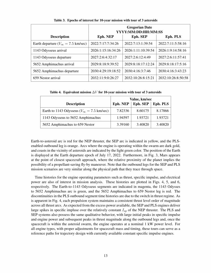
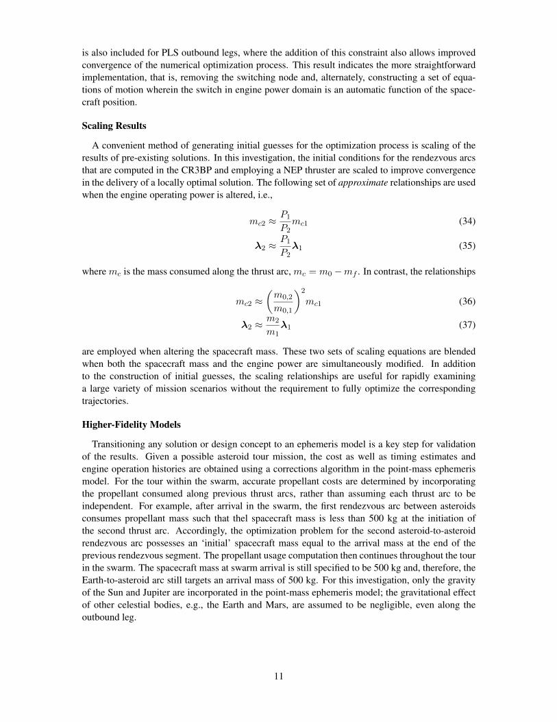
Table 3. Epochs of interest for 10-year mission with tour of 3 asteroids
Gregorian DateYYYY:MM:DD:HH:MM:SS
Description Eph. NEP Eph. SEP Eph. PLS
Earth departure (V∞ = 7.5 km/sec) 2022:7:17:7:34:26 2022:7:13:1:39:54 2022:7:11:5:58:16
1143 Odysseus arrival 2026:1:15:16:34:26 2026:1:11:10:39:54 2026:1:9:14:58:16
1143 Odysseus departure 2027:2:6:4:32:17 2027:2:6:12:4:49 2027:2:6:11:57:41
5652 Amphimachus arrival 2029:8:18:9:39:52 2029:8:18:17:12:24 2029:8:18:17:5:16
5652 Amphimachus departure 2030:4:29:19:18:52 2030:4:16:3:7:46 2030:4:16:3:43:23
659 Nestor arrival 2032:11:9:0:26:27 2032:10:26:8:15:21 2032:10:26:8:50:58
Table 4. Equivalent mission ∆V for 10-year mission with tour of 3 asteroids
Value, km/secDescription Eph. NEP Eph. SEP Eph. PLS
Earth to 1143 Odysseus (V∞ = 7.5 km/sec) 7.82336 8.60175 8.17866
1143 Odysseus to 5652 Amphimachus 1.94597 1.93721 1.93721
5652 Amphimachus to 659 Nestor 3.39160 3.40820 3.40820
Earth-to-asteroid arc is red for the NEP thruster, the SEP arc is indicated in yellow, and the PLS-enabled outbound leg is orange. Arcs where the engine is operating within the swarm are dark gold,and coasts in the vicinity of asteroids are indicated by the light green color. The position of the Earthis displayed at the Earth departure epoch of July 17, 2022. Furthermore, in Fig. 3, Mars appearsat the point of closest spacecraft approach, where the relative proximity of the planet implies thepossibility of a propellant-saving fly-by maneuver. Note that the outbound legs for the SEP and PLSmission scenarios are very similar along the physical path that they trace through space.
Time histories for the engine operating parameters such as thrust, specific impulse, and electricalpower are also of interest in mission analysis. These histories are plotted in Figs. 4, 5, and 6,respectively. The Earth-to-1143 Odysseus segments are indicated in magenta, the 1143 Odyssesto 5652 Amphimachus arc is green, and the 5652 Amphimachus to 659 Nestor leg is red. Thediscontinuities in the PLS outbound segment time histories are due to the switch in thrust regime. Asis apparent in Fig. 4, each propulsion system maintains a consistent thrust level order of magnitudeacross all thrust arcs. As expected from the excess power available, the SEP and PLS engines deliverlarge spikes in specific impluse over the relatively constant Isp of the NEP thruster. The PLS andSEP systems also possess the same qualitative behavior, with large initial peaks in specific impulseand engine power and subsequent peaks in thrust magnitude along the outbound legs and, once thespacecraft is within the asteroid swarm, the engine operates at a nominal 1 kW power level. Forall engine types, with proper adjustments for spacecraft mass and timing, these tours can serve as areference paths for trajectory design with currently available constant specific impulse engines.
13

Sun
Earth
5652 Amphimachus
659 Nestor
1143 Odysseus
Figure 2. Inertial trajectory view for tours with initial target 1143 Odysseus: out-bound legs (red, orange, yellow), thrust arcs (gold), coasts in the vicinity of asteroids(green).
CONCLUSIONS
An automated algorithm to generate trajectories for asteroid tour missions is extended to incor-porate several categories of low-thrust, variable specific impulse propulsion systems. While appliedto the construction of Sun-Jupiter Trojan asteroid survey missions, the procedure is not limited bydynamical regime and is readily extended to other mission architectures. Nuclear electic and so-lar electric propulsion are modeled as constant- and varying-power systems, respectively, while apower-limited SEP engine is analyzed as a hybrid system comprised of constant- and varying-powerthrust regimes. Baseline trajectories computed using the CR3BP and a NEP engine are scaled ap-propriately by the desired engine type and available engine power; these initial guesses are then op-timized in a point-mass ephemeris model. Engine operation is determined via an indirect, calculusof variations optimization approach, where the constant- and varying-power systems follow distinctcontrol laws and equations of motion. Results indicate that optimal operation of a PLS hybrid sys-tem implies continuity in the Euler-Lagrange co-state vectors across a switch in thrust regime, anobservation that can reduce implementation time and computational overhead. This continuity alsosupports an assessment that the indirect optimization schemes reveal optimal paths through space,regardless of thrust system or switches in engine operation domains. Furthermore, scaling rela-tionships for engine operation and performance quantities offer an avenue for rapid investigation ofmission scenarios and spacecraft parameters.
Several avenues are to be pursued for further investigation. In particular, higher-fidelity modelingof the paths of natural bodies in the solar system increases the accuracy of the resulting designs for
14

Sun
Earth Jupiter
Mars
Figure 3. Views of the trajectory path relative to the Sun-Jupiter rotating frame fortours with initial target 1143 Odysseus: outbound legs (red, orange, yellow), thrustarcs (black), coasts in the vicinity of asteroids (green).
both the asteroid-to-asteroid arcs as well as the end-to-end tour design. Of particular importance isthe increase in the fidelity of the model in the vicinity of the Earth-Moon region and near-passagesof other massive bodies, such as Mars. The automated procedure can be further enhanced to identifyclose passages and fly-bys of intermediate objects in the solar system, e.g., other asteroids withinthe swarm or along the outbound leg from Earth. Furthermore, additional asteroids of interest maybe included in the initial survey, and the options to design tours within the swarm can be expandedbeyond pre-computed libraries of solutions. Finally, the automated procedure may be applied toother scenarios requiring multiple low-thrust or hybrid propulsion arcs, whether as part of a baselineor an extended trajectory design.
ACKNOWLEDGEMENTS
This work was conducted at Purdue University and the Jet Propulsion Laboratory and is sup-ported by the Purdue Research Foundation and a NASA Office of the Chief Technologist’s SpaceTechnology Research Fellowship, NASA Grant NNX12AM61H. Many thanks to Wayne Schlei,who helped immensely with the trajectory images, and the technical personnel of the Jet PropulsionLaboratory, Mission Design and Navigation Section.
REFERENCES[1] N. Augustine, W. Austin, C. Chyba, C. Kennel, B. Bejmuk, E. Crawley, L. Lyles, L. Chiao, J. Greason,
and S. Ride, “Seeking a Human Spaceflight Program Worthy of a Great Nation,” tech. rep., U.S. HumanSpaceflight Plans Committee, 2009.
[2] M. Brown, “Mission Concept Study: Trojan Tour Decadal Study,” tech. rep., National Aeronautics andSpace Administration, 2011.
[3] J. Stuart and K. Howell, “An Automated Search Procedure to Generate Optimal Low-Thrust Ren-dezvous Tours of the Sun-Jupiter Trojan Asteroids,” 23rd International Symposium on Spaceflight Dy-namics, Pasadena, CA, October 29 - November 4 2012.
[4] D. Goebel, J. Brophy, J. Polk, I. Katz, and J. Anderson, “Variable Specific Impulse High Power IonThruster,” Joint Propulsion Conference, Tucson, Arizona, AIAA/ASME/SAE/ASEE, July 2005. PaperNo. AIAA 2005-4246.
[5] A. A. R. Company, “VASIMR Technology,” Accessed: November 28, 2010.
15
a. NEP b. SEP
c. PLS
Figure 4. Thrust profiles for the outbound leg (pink) as well as the first (green) andsecond (red) asteroid rendezvous arcs for the mission scenario with the asteroid 1143Odysseus as the initial target within the swarm.
[6] K. Komurasaki, Y. Arakawa, and H. Takegahara, “An Overview of Electric and Advanced PropulsionActivities in Japan,” Proceedings of Third International Conference of Spacecraft Propulsion, Cannes,France, October 2000, pp. 27–39.
[7] M. Volle, “Optimal Variable-Specific-Impulse Rendezvous Trajectories Between Halo Orbits,” Inter-national Symposium on Space Flight Dynamics, Kanazawa, Japan, Japan Society for Aeronautical andSpace Sciences and ISTS, June 2006. Paper No. ISTS 2006-d-73.
[8] R. Russell, “Primer Vector Theory Applied to Global Low-Thrust Trade Studies,” Journal of Guidance,Control, and Dynamics, Vol. 30, March-April 2007, pp. 460–473.
[9] J. Senent, C. Ocampo, and A. Capella, “Low-Thrust Variable-Specific-Impulse Transfers and Guidanceto Unstable Periodic Orbits,” Journal of Guidance, Control, and Dynamics, Vol. 28, March-April 2005,pp. 280–290.
[10] G. Mingotti, F. Topputo, and F. Bernelli-Zazzera, “Combined Optimal Low-Thrust and Stable-ManifoldTrajectories to the Earth-Moon Halo Orbits,” New Trends in Astrodynamics and Applications III,Vol. 886, February 2007, pp. 100–112.
[11] C. Martin and B. Conway, “Optimal Low-Thrust/Invariant Manifold Earth Moon Transfer Trajectories,”Space Flight Mechanics Meeting, San Diego, California, AAS/AIAA, February 2010. Paper No. AAS10-105.
[12] J. Betts, “Survey of Numerical Methods for Trajectory Optimization,” Journal of Guidance, Control,and Dynamics, Vol. 21, March-April 1998, pp. 193–207.
[13] A. E. Bryson, Jr. and Y.-C. Ho, Applied Optimal Control. Waltham, Massachusetts: Blaisdell Publish-ing, 1969.
[14] P. E. Gill, W. Murray, and M. A. Saunders, “SNOPT: An SQP algorithm for large-scale constrainedoptimization,” Society for Industrial and Applied Mathematics Journal of Optimization, Vol. 12, 2002,pp. 979–1006.
16

a. NEP b. SEP
c. PLS
Figure 5. Specific impulse profiles for the outbound leg (pink) as well as the first(green) and second (red) asteroid rendezvous arcs for the mission scenario with theasteroid 1143 Odysseus as the initial target within the swarm.
[15] Solar System Dynamics Group, HORIZONS System. Jet Propulsion Laboratory.http://ssd.jpl.nasa.gov/?horizons.
[16] H. B. Keller, Numerical Solution of Two Point Boundary Value Problems. Philadelphia, Pennsylvania:Society for Industrial and Applied Mathematics, 1976.
17

b. SEP c. PLS
Figure 6. Operating power profiles for the outbound leg (pink) as well as the first(green) and second (red) asteroid rendezvous arcs for the mission scenario with theasteroid 1143 Odysseus as the initial target within the swarm. Time histories for theNEP system are constant at 1 kW and are not shown.
18