aap 4200 de½m kitapcýgi/aap...preface ⅰ preface thank you for purchasing products from our...
TRANSCRIPT

AAP 4200 DE

İTHALATÇI FİRMA / IMPORTER COMPANYAKSA JENERATÖR SAN. A.Ş.
Gülbahar Caddesi 1. Sokak 34212 No:2Güneşli / İstanbul
T: + 90 212 478 66 66F: + 90 212 657 55 16
e-mail: [email protected]
ÜRETİCİ FİRMA / MANUFACTURER COMPANYCHANGHOU CHANGFA IMP. EP.CO.LTD.
YETKİLİ SERVİS / AUTHORIZED SERVICEAKSA SERVICE & SPARE PARTSAdres/Adress: Murat Bey Beldesi
Güney Girişi Cad. No:834540 Çatalca / İstanbulT: + 90 212 887 11 11F: + 90 212 887 10 20
e-mail: [email protected]
AKSA GENERATORAKSA POWER PORTABLE SERIES USER MANUAL
PLEASE READ THIS MANUAL CAREFULLY; IT CONTAINS IMPORTANT SAFETY INFORMATION
DİZEL JENERATÖR / DIESEL GENERATOR
AAP 4200 DE
Adres:Changfa Industrial Park,South of Changzhou,Jiangsu,China
Tel:+86-519-6237006 e-mail:[email protected]


PREFACE
ⅰ
PREFACE Thank you for purchasing products from our company.
The manuals will help you to operate and maintain the machines rightly. Please make sure to read the manuals carefully before the operating the machines. Then the generators can work in the best condition and prolong the life.
This manual will explain how to operate and service your generator set. If you have any questions or suggestions about this manual, please contact us by the email
.Consumers should notice that this manual might differ slightly from the actual product as more improvements are made to our products. Some of the pictures in this manual may differ slightly from the actual product as well. AA K SA Group reserves the right to make changes at any time without notice and without incurring any obligation.
Please notice the following warning. If you will not operate the machines according to the manuals, there may be body injury and dead. So you MUST operate the machines after the fully understanding of the manuals.

TABLE OF CONTENTS
TABLE OF CONTENTS Chapter 1 Technical Specifications and Data………………….1
1-1 Technical specifications and data……………………………………1
1-2 Basic operating parameters…………………………………………..2
1-3 General dimensions and overview of the generators………………2 1-4 Parts name and control panel………………………………………….3
Chapter 2 Operating the Diesel Generator……………………….....4
2-1 Main points of safety during operation of the generator…………..4
2-2 Preparation before operation…………………………………………5
2-3 Checking the operation of the diesel engine………………………..8
2-4 Starting the generator set……………………………………………..8
2-5 Proper operation of the generator set………………………………..9
2-6 Loading…………………………………………………………………10
2-7 Stopping the generator………………………………………………11
Chapter 3 Maintenance……………………………………………………..12
3-1 Maintenance schedules……………………………………………...12
3-2 Storing for long periods of time……………………………………...13
Chapter 4 Troubleshooting……………………………………………….14
4-1 Troubleshooting procedures………………………………………...14
4-2 Questions and doubts…………………………………………….….14
Chapter 5 Circuit diagram………………………………………………….15
Appendix ⅠType of socket……………………………………………………..18
Appendix ⅡGeneral power list of appliance…………………………………20

TECHNICAL SPECIFICATIONS AND DATA
1
CHAPTER 1 TECHNICAL SPECIFICATIONS AND DATA
1-1 Technical specifications and data Single-cylinder diesel generator
Type Item
Kind Single phase
Frequency(Hz) 50
Max power (KVA) 4.5
Rated power (KVA) 4.2
Voltage (A.C)(V) 220V,230V,240V,110/220V,120/240V,115/230V
Excitation mode Self-excitation brushless or
Self-excitation constant voltage(AVR)
Revolution (r/min) 3000
Voltage (D.C)(V) 12
Current (D.C)(A) 7
Noise level dB(A)/7m (0-100%load) 70-74
Power factor cosφ 1
Gen
erat
or
Insulation grade F
Model of power CF186F (E)
Kind 4-stroke single-cylinder air cooled direct injection
Max power (kW/rpm) 6.5
Bore × stroke (mm) 86×70
Cylinder displacement (ml) 406
Cooling system Force air-cooled
Lubricating system Pressure splash, duplex type lubrication
Volume of lube oil (L) 1.65
Start system Electric start
Die
sel e
ngin
e
Fuel Diesel fuel
Fuel tank volume (L) 15
Low oil pressure protection Have
Total weight (kg) 186
Set
Overall dimensions (mm) 970×580×785
Note: Get this power only after 30 hours’ initial run.
AAP 4200 DE

TECHNICAL SPECIFICATIONS AND DATA
2
1-2 Basic operating parameters
1-2.1 Under the given conditions, the generator will output the specified power in the table listed below.
Table 1 Height above sea level (ft) Ambient temperature (
oF) RH
0 +60 (+20 oC) 60%
<3280.8 (<1000 m) 41~104 (5-40 oC) 90%
1-3 General dimensions and overview of the generators
Please refer to the specification for the right dimension for different models.

TECHNICAL SPECIFICATIONS AND DATA
3
1-4 Parts name and control panel 1-4.1 Parts Name

OPERATING THE DIESEL GENERATOR
4
1-4.2 control panel
CHAPTER 2 OPERATING THE DIESEL GENERATOR
2-1 General main points of safety during operation of the generator set.
In order to operate the generator set safely, please follow all the instructions provided in this manual carefully. Doing so otherwise may lead to accidents and or equipment damage. 2-1.1 Fire prevention
Do not use gasoline, kerosene or other fuels other than light diesel fuel. Keep all flammable fuels away from the generator as the generator may
spark and ignite these gases. Keep the diesel generator at least 1.5 meters away from buildings and or
other equipment. Always operate your diesel generator on a level site.
2-1.2 Prevention from inhaling exhaust gases. Never inhales exhaust gases emitted by the engine. The exhaust gases contain toxic carbon monoxide. Never operate your generator in places with poor ventilation. In order to operate this machinery indoors, a suitable ventilation system for the building is

OPERATING THE DIESEL GENERATOR
5
required to draw the poisonous exhaust gases out. 2-1.3 Prevention from accidental burns
Never touch the muffler and its cover when the diesel engine is running. Never touch the muffler and cover after the diesel engine has been used,
as the muffler remains hot for a good period of time. 2-1.4 Electric shock and short circuits
Never touch the generator if the generator is wet. Also never touch the generator if your hand is wet.
Never operate your generator if the weather conditions call for any type of precipitation such as rain, snow, or fog.
To prevent electrical shocks, the generator should be grounded. Please refer to Fig. 2-1 before beginning to use the electric generator.
Fig. 2-1
NOTE When connecting devices to the generator, make sure all other devices are rated lower than the generators output. Any generator socket should not be overloaded over its regulated limit. 2-1.5 Other safety points Before operating this generator, all operators should have a good knowledge of how to break the circuit if any accidents occur. Also, all operators should be familiar with all the switches and functions of the generator before using this machine. While operating the generator, wear safe shoes and suitable clothes during operation. Always keep children and animals away from the generator. 2-1.6 Battery Wear protective gear when working with the battery to protect your eyes, skin, and clothing,. If you come in contact with the electrolytic liquid, wash it immediately with clean water. Also, if the electrolytic liquid comes in contact with your eyes, see a doctor immediately.
2-2 Preparation before operation 2-2.1 Fuel choices and fuel treatment
Use only light diesel fuel. Otherwise it will be difficult to start the generator. The fuel should be filtered clean. Never let dust and water mix with fuel in
the fuel tank. Otherwise it will clog the fuel lines and oil nozzles. It may also damage your pressure pump.
Note It is dangerous to overfill the fuel tank. Never exceed the red piston in the filter.
Type AAP4200DE The effective volume of fuel tank: 14.5L

OPERATING THE DIESEL GENERATOR
6
a. After purchasing fuel, put it into a drum and let it sit for 3-4 days. Otherwise it contains granule, which will result to clog the fuel lines. b. 3-4 days later, insert half of the fuel sucker into the drum, (water and impurities stay in the lower portion of the drum) .Otherwise they will be taken in. Contaminated fuel will cause accelerated wear to fuel system part.
NOTE Never smoke near the opening of the fuel tank. Do not let sparks get near the fuel or fuel tank and do not overfill tank. After filling, tighten the fuel cap.
2-2.2 Check and fill engine oil
Make sure the generator is on level ground and remove the dipstick from the engines. if not, the oil level of the engine which show us are wrong.
Check if the oil level is between the high limit and low limit. If the engine is new or oil is not enough, fill the engine with the right engine oil(10W30).
Put the dipstick back into the hole to check the engine oil level.
Choose the right engine oil Engine oil is the most important factor in determining the life of your generator engine. If you use poor engine oil or if you don’t change the oil regularly, the piston and cylinder will wear easily or seize up. Also, the life of the other parts in your engine such as bearings, and other rotating parts will shorten considerably.
Oil dipstick

OPERATING THE DIESEL GENERATOR
7
NOTE Although there is an alarm system to check for low oil pressure, it is always a good idea to check the amount of oil inside the engine. If the oil level is low, fill it before starting the engine. A good time to drain the oil from the engine is when the diesel engine is still hot. If the engine is fully cooled, it is more difficult to drain all the oil out or some impurities will remain in the engine.
WARNING DO NOT fill engine oil when the machines are running.
2-2.3 Checking the air filter (1) Open the cover of generators, you will see the air filter assembly. (2) Loosen the butterfly nut of air filter, take the cover of the air filter off and take the air filter element out.
NOTE Do not use detergent to wash the air filter element. When the performance of the engine decreases or when the color of the
exhaust gases is bad, exchange the filter element. Never start the engine without the air filter as foreign objects may enter the
intake and damage the engine.
(3) After replacing the air filter element, replace the cover and tighten the butterfly nut firmly. If not replace the air filter immediately, the dust in the air will not be adsorbed. In that case, it stands a good chance to block the air way.
2-2.4 Check the oil way The fuel and oil in a new engine is drained before sold. Before you start the engine, please fill the fuel tank and engine oil first. Then, check to see if there are air bubbles in the engine. If there are, follow these procedures. Loosen the connecting nut between the oil injection pump and oil pipe. Bleed the air from the system until there are no more bubbles. Then replace the connecting nut and tighten it.
2-2.5 Check the generators (1) Close the power switch and disconnect from any load. Otherwise it may
cause electric shock. Even make injures or death.
Air filter cover

OPERATING THE DIESEL GENERATOR
8
Knob handle
WARNING Make sure to close the power switch. Make sure to ground the generators. (2) How to use double voltage generators Push the voltage switch to the right voltage you will use.
WARNING Make sure to disconnect any load before starting the generators. It is very dangerous if not.
2-3 Checking the operation of the diesel engine 2-3.1 Low-pressure alarm system.
AKSA diesel engines have a low-pressure sensor system where if the oil pressure drops too low, the sensor will shut the engine off. The purpose of having this system is to ensure that the engine does not seize up. If there is not enough oil in the engine, the temperature of the oil will be raised too high. On the contrary, if there is too much oil in the engine, the engine oil can slow the engine down considerably.
2-3.2 How to open the case door/cover (1) Open the case door: Pull the handle outward and open the door. Do these checks daily.
(2) Loosen the outer cover bolt of the air filter and outer cover of the oil nozzle, and then check the air filter.
(3) Check the outer cover of the oil nozzle. Loosen the butterfly nut and open the outer cover.
2-3.3 Engine break in When you purchase a brand new engine, the engine must be properly broken in. The break in period is about 20 hours. (1) Avoid overloading the engine when brand new (2) Change the engine oil according to specifications. An oil change for a brand new engine is about 20 hours or every month, an older engine, the oil change is about 100 hours or three months. If not breaking in, it will reduce the serving life, reliability and cost performance of the engine. At last, the life of the generator also be shortened. 2-4 Starting the generator set 2-4.1 Starting. (1) Make certain the generator is on a " FLAT " or " LEVEL SURFACE ". If the engine is tilled, fuel spillage may result. (2) Disconnect all electrical loads from the generator. Never start and stop the generator with electrical devices plugged in or turned on. Otherwise it will result

OPERATING THE DIESEL GENERATOR
9
to short circuit, even break down the starter motor. (3) Turn the Fuel Valve to the " ON " position. Otherwise fuel will be not enough to start the generator. (4). Push the speed level to " run " Position. If do not so, the start of generator will be fail. (5) Insert the ignition key to the “ off ” position. (6) Electric Start: Turn the ignition key to the " Start " position and hold until engine starts. Otherwise it will be abnormal to electrify. ( If the engine fails to start within five seconds, release the key and wait at least ten seconds before attempting to start the engine again. If holding on starting, it will heat up motor.) (7) As engine warms up, move the ignition key to " on " position. Otherwise the fuel way will cause serious trouble.
2-4.2 Battery
NOTE If you crank the starter too long, the battery may be drained too much to provide enough energy for proper engine ignition. Also, when the diesel engine is operating, let the key retain in the “ON” position.
IMPORTANT NOTE All of our units come with a maintenance free battery. You do not need to add any battery acid.
2-5 Proper operation of the generator set 2-5.1 Operating the diesel engine 1. Pre-heat the diesel engine for 3 minutes under no load conditions. 2. First check the low oil pressure indication light in the panel. If the light is red, please fill into enough oil. 3. Do not adjust the speed limit regulation bolt or the fuel adjustment bolt. These bolts have been set by the factory already, changing them will affect the properties of the engine performance. 2-5.2 Checks during engine operation 1. Check to see if there are abnormal noises. Check the joint of oil passages, fuel passages, water passages and air passages frequently to find out whether there is any leakage. If any, remove at once. Otherwise serious troubles may be caused. 2. Check to see if the performance is good or bad. 3. Check the color of the exhaust gases (whether it is too black or too white). If any of these conditions exist, stop the engine and find the cause of the

OPERATING THE DIESEL GENERATOR
10
problem. If no problems are found, please contact your local dealer or our nearest company branch.
2-6 Loading 2-6.1 Connecting Electrical Loads: 1. Let the engine stably and warm up for a few minutes after starting. 2. Plug in and turn on the desired VOLTAGE AC Output with electrical loads.
IMPORTANT NOTE DO NOT connect 3-phase loads to SINGLE PHASE Diesel Generator. DO NOT overload this generator. To prolong the life of your generator and properly connect your appliances, please follow these steps to add electrical load: 3. Start the generator with NO ELECTRICAL LOAD ATTACHED. 4. Allow the engine to run for several minutes to STABILIZE. 5. Plug in and turn on the first item. It is best to attached the item with the LARGEST LOAD first. 6. Allow the engine to stabilize. 7. Plug in and turn on the next item. 8. Allow the engine to STABILIZE. 9. Repeat step 4-5 for each capacity when adding loads.
2-6.2 Output of electricity 1. Raise the revolutions per minute (turn the speed handle to the max setting)
of the generator to get the maximum power out of the generator. If not, the automatic voltage regulator device will excite and doing this for long periods of time will cause the AVR to burn. For the rated speed of the generator, please refer to Chapter 1, item 1-1 technical specification and data.
2. Observe the pointer of the voltmeter, it should point to the voltage you need 5%. Meanwhile put the switch in the GEN (generator) position. The AC voltage from the socket of the power supply can be output.
2-6.3 Charging the battery 1. For the electric starter on the generator sets, the 12V battery is automatically
charged through the regulator on the side of the engine when it is running. 2. If the generator is not used for long periods of time, the battery should be
disconnected to avoid energy loss from the battery. 3. Do not connect the negative and positive terminals of the battery together at
NOTE Do not start more than two devices simultaneously. Each device should be started one by one to prevent overloading the generator. The generator should be running at 3600 revolutions per minute in order to achieve the (60 Hz) frequency. The speed of the engine can be adjusted from the speed governor.
OPERATING THE DIESEL GENERATOR
11
any time. Doing so will damage the battery and cause serious injuries. 4. Do not reverse the polarities when attaching the battery cables to the battery.
Doing so will damage both the battery and the electric starter. 5. When charging the battery, the battery produces flammable gases. Do not
smoke, let flames, and sparks get near the battery while it is charging as this may cause a fire.
To avoid sparking while connecting the cables to the battery, first, connect the cables to the battery then to the motor. To disconnect battery cables, first disconnect the motor end of the cable.
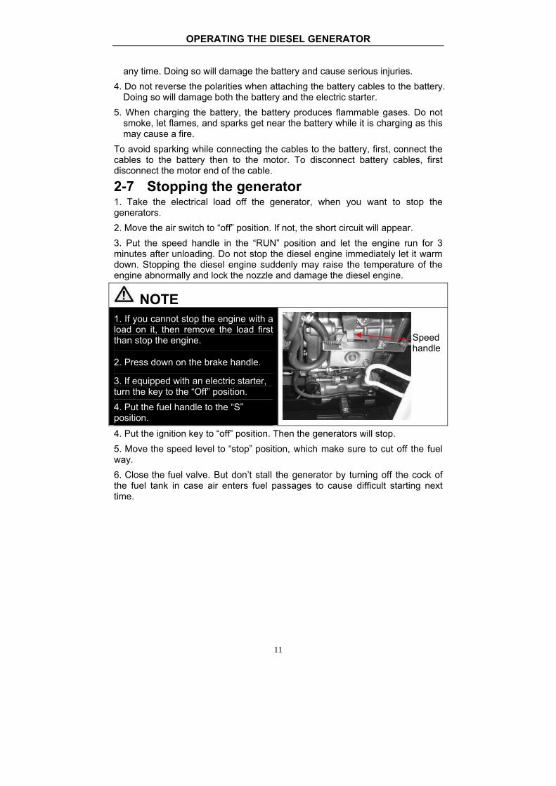
2-7 Stopping the generator 1. Take the electrical load off the generator, when you want to stop the generators. 2. Move the air switch to “off” position. If not, the short circuit will appear. 3. Put the speed handle in the “RUN” position and let the engine run for 3 minutes after unloading. Do not stop the diesel engine immediately let it warm down. Stopping the diesel engine suddenly may raise the temperature of the engine abnormally and lock the nozzle and damage the diesel engine.
NOTE 1. If you cannot stop the engine with a load on it, then remove the load first than stop the engine.
2. Press down on the brake handle.
3. If equipped with an electric starter, turn the key to the “Off” position. 4. Put the fuel handle to the “S” position.
4. Put the ignition key to “off” position. Then the generators will stop. 5. Move the speed level to “stop” position, which make sure to cut off the fuel way. 6. Close the fuel valve. But don’t stall the generator by turning off the cock of the fuel tank in case air enters fuel passages to cause difficult starting next time.
Speed handle

MAINTENANCE
12
CHAPTER 3 MAINTENANCE 3-1 Maintenance schedules Keeping your generator well maintained will prolong the life of your generator. Everything needs to be checked including the diesel engine, generator, control cabinet, and frame. For overhauling procedures, please refer to the instruction manual of the relative subassembly. If you need these manuals, please call our company and we will send you one. Before starting the maintenance, make sure the diesel engine is off. Please refer to the Table 3-1 for the proper maintenance schedule. Table 3-1. Maintenance schedule for diesel generator set Time Item Everyday
After 1 month or 50hours
Every 3 month or 200 hours
Every 6 month or 400 hours
Every 1year or 1000 hours
Check the fuel level and refill
○Before starting
Drain the fuel tank ○ Check and fill enough engine oil ○ Clean the fuel filter ○
Check fuel oil leakage
○after every operating
Check and screw each fastened part ○
●screw the bolt of cylinder head firmly
Check injector ● Check injection pump ● Check fuel pipe ●If necessary
exchange it Check the lube. oil level in the oil pan and refill
○before starting
Replace the lube. oil ○the first
time ○the second time and afterward
Clean lube. Oil filter ○the first
time ○the second time and afterward
Check the air cleaner element ○the first
time ○the second time and afterward
Change the core of air filter If damaged or smeary , change it in time
Check the battery liquid level and refill
○
Adjusting the intake and exhaust valve clearance
●the first time
●the second time and afterward
Grind air intake and air exhausted gate ● Exchange piston ring ● Check electric brush and slide ring ● Check insulation resistance The time of stop is over 10 days ○ Note: the quality period of the injector and injection pump is 1500 hours
or two years. There into,● means it should operate with special tools, or can be checked by dealer.

MAINTENANCE
13
Dipstick Oil drain bolt
3-1.1 Changing the engine oil (every 100 hours) Take the oil cover off. Remove the oil drain plug when the diesel engine is still hot. Be careful of hot oil and hot engine as you may get burned. The bolt is located at the bottom of the cylinder. After draining the oil, put the bolt back and tighten it. Then fill with the proper engine oil to the proper level.
3-1.2 Air filter maintenance schedule 1. Clean air-filter every 6 months or 500 hours of operation. 2. If necessary, exchange it. 3. Do not use detergent to clean air filter element.
NOTE Never start the engine without the air filter. This can cause serious damage to the engine if foreign objects enter the intake system. Always change the air filter on time. 3-1.3 Fuel filter maintenance 1. The fuel filter should be cleaned often to keep the engine running at maximum performance. 2. The recommended time period for cleaning the fuel filter is 6 months or 500 hours of operation. a. To do this, first drain the fuel from the fuel tank. b. Loosen the small screws on the fuel switch and remove the fuel filter form the port. Use diesel fuel to clean the fuel filter. Also, remove the fuel injector and clean the carbon deposit around it. The recommended time period for this is 3 months or 100 hours. 3-1.4 Cylinder head bolt tensions The cylinder head bolts should be tightened to specifications please refer to the diesel engine manual for specifications and the special tools required to do this. 3-1.5 Battery check Make sure the battery acid is full. The engine uses a 12V battery. Due to numerous starting cycles, the battery acid may be used up. Also, before filling, verify that the battery is not damaged in any way. Add distilled water to the battery when filling. Perform checks on the battery once a month. 3-2 Storing for long periods of time If your generator needs to be stored for long periods of time, the following preparations should be made. 1. Start the diesel engine for 3 minutes then stop it. 2. When the engine is still hot, change the engine oil with new engine oil of the proper grade. 3. For electric started generator, press the decompression handle down and crank the engine for 2-3 seconds. To do this, put the starter switch in the “Start” position. (Do not start the diesel engine) 4. Clean the engine and store it in a dry place.

TROUBLESHOOTING
14
CHAPTER 4 TROUBLESHOOTING 4-1 Troubleshooting procedures
Causes of malfunction Remedy Not enough fuel Add enough fuel The switch of fuel is not at “OPEN” position.
Turn the switch of fuel to “OPEN” position.
High-pressure pump and nozzle do not inject fuel or the injected amount is less.
Disassemble the nozzle and adjust it at test table.
Speed control lever is not at “RUN” position.
Turn speed control lever to “RUN” position.
Check level of lubrication oil.
The standard oil amount of lubricating oil should be between high graduation “H” and low graduation “L”.
It is not quick and powerful to pull reactive starter.
Start diesel engine in accordance with the requirements of “start operation procedures”.
Nozzle exist dirt. Clean the nozzle.
Die
sel c
anno
t be
star
ted.
Accumulator has not electricity. Charge the accumulator or exchange it.
Master switch (NFB) is not be switched on.
Turn master switch handle to “ON” position.
Carbon brush of generator was worn. The contact is bad. Exchange the carbon brush.
The contact of socket is bad. Adjust the contact feet of socket.
The rated revolution of engine cannot be reached.
Make it reach to the rated revolution in accordance with the requirements.
AVR automatic governor is damaged. Exchange it.
Gen
erat
or c
anno
t gen
erat
e el
ectri
city
an
d ha
s no
t wel
ding
vol
tage
The potentiometer of current regulation for electric welding is damaged.
Exchange it.
If you are still having trouble, please contact with your nearest dealer or with our company directly if necessary. 4-2 Questions and doubts If you do not understand anything or have any questions, please feel free to contact our company directly.of some information you should have ready before contacting us. 1. Model of diesel engine generator and engine model number. 2. State of residency. 3. Number of hours of operating equipment along with the problem that occurred. 4. A detailed condition and time when the problem occurred, in other words, climate and atmosphere.

CIRCUIT DIAGRAM
15
CHAPTER 5 CIRCUIT DIAGRAM Figure 5-1 single-phase double voltage circuit diagram

CIRCUIT DIAGRAM
16
Figure 5-2 single-phase single voltage circuit diagram

CALIFORNIA EMISSIONS CONTROL WARRANTY STATEMENT
17
Figure 5-3 three-phase circuit diagram

18
Appendix Ⅰ :Types of sockets Code Description Specification Picture
S01 S.A socket 25A, 250V
S02 British socket 32A, 240V
S03 British socket 16A, 240V
S04 Square American type-socket 20A, 120V
S05 Germany socket 16A, 250V
S06 Three-phase five holes socket 16A, 415V
S07 French socket 16A, 250V
S08 Three-phase four holes socket 16A, 215V
S09 American type
4-hole unit loose socket
30A, 250V

19
Code Description Specification Picture
S10 American double socket 20A, 125V
S11
3-hole unit loose socket
(UL-authentication optional)
30A, 250V
S12 Australian socket 16A, 250V
S13 Swiss socket 10A, 250V

20
Appendix Ⅱ :General power list of appliance
To select the correct size generator for your needs you should make a list of which tools and/or appliances you intend to operate with your generator. The chart below contains approximate wattages and should give you an idea of the size generator you will need. After you make your list of devices to be used, (be sure to consider starting wattages) you will add the total watts and select the generator that can supply that amount of power.
House Hold Running Wattage Requirements
Starting Wattage Requirements
Coffee Maker 1750 1750 Dishwasher 1450 1800
Electric Fry Pan 1300 1300
Electric Range 6 Inch Elements 1500 1500 8 Inch Elements 2100 2100
Microwave Oven 625 watts 625 800
Refrigerator or Freezer 700 2200 Toaster 2-slice 1050 1050 Toaster 4- Slice 1650 1650
Automatic Clothes Washer 1150 2300
Clothes Dryer Gas 700 1800 Dehumidifier 650 800
Electric Blanket (queen size) 650 800
Garage Door Opener ¼hp 550 1100
Garage Door Opener 1/3 hp 725 1400
Furnace Fan 1/8 hp 500 1000 Furnace Fan 1/6 hp 750 1500 Furnace Fan ¼ hp 900 1800 Furnace Fan 1/3 hp 1000 1800 Furnace Fan½hp 1200 1500
Hair Dryer 300 - 1500 300 - 1500 Clothes Iron 1200 1200
Lights As Indicated As Indicated Radio 50 - 200 50 - 200
Well or Sump Pump 1/3 hp 750 1500
Well or Sump Pump 1/2 hp 1000 2000
Well or Sump Pump 1 hp 2300 4500
Color Television 13 to 300 300

21
House Hold Running Wattage Requirements
Starting Wattage Requirements
32 VCR 50 50
Computer 150 150 Modem 25 25 Printer 100 100
Vacuum Cleaner Upright 800 1100
Vacuum Cleaner Canister 1100 1500
Central Air Conditioner 10.000 BTU 1500 2200 20.000 BTU 2500 3300 24.000 BTU 3800 4950 40.000 BTU 6000 7800
Air Compressor ½ hp 1000 2000 1 hp 1500 4500
1½hp 2200 6000 2 hp 2800 7700
Bench Grinder 6-inch 720 1000 Bench Grinder 8-inch 1400 2500 Bench Grinder 10-inch 1600 3600 Electric Cultivator 1/3
hp 700 1400
Electric Grass Trimmer 500 650 Drum Mixer ¼hp 700 1400 Mercury/Halogen 1000 1000
Floor Polisher 16-inch,¾hp 1400 3100 20-inch, 1hp 1600 4500
Hand Drill¼inch 350 350 Hand Drill 3/8 inch 400 400
Hand Drill½inch 600 600 Submersible
Water Pump 400gp 200 400 Water Pump
Centrifugal Type 500 650
Wet And Dry Vacuum 1.7 hp 900 900 2.5 hp 1300 1300
Saws Worm Drive (chop saw) 1800 2600
Circular Saw 6½inch 800 1200 Circular Saw 7¼inch 1400 2300

22
House Hold Running Wattage Requirements
Starting Wattage Requirements
Circular Saw 8 ¼ inch 1800 3000 Electric Chain Saw 1100 1400 Table Saw 9 inch 1500 3000 Table Saw 10 inch 1800 4500
Electric Welder 70 amp 2800 2800 Band Saw 1100 1400
Electric Fence, 25 miles 250 250
Stock Tank De-Icer 1000 1000 Grain Cleaner 650 1000
Portable Conveyer½hp 1000 2400 Grain Elevator¾hp 1000 2400
Milk Cooler 1100 2300 Mixer 3½Cubic Feet
¾hp 2800 7700 Milking Machine, 2 hp 1100 2300


AKSA JENERATÖR SANAY ĐĐ A.Ş.
DECLARATION OF CONFORMITY AT – UYGUNLUK BEYANI
Üretici / Manufacturer : AKSA Jeneratör San.A. Ş.
Adres / Adress : Gülbahar Cd. 1.Sokak, Güne şli 34212 Đstanbul / Türkiye
Ürün Kodu / Product Code : AAP 4200DE /……………………………
Ürün Açıklaması : Diesel Portable Genset Production Description Dizel Portatif Jeneratör Deklerasyon / Declaration
AKSA Jeneratör San. A. Ş olarak, yukarıda bilgileri verilmi ş olan ürünün a şağıdaki Avrupa Birli ği direktiflerine, standartlara ve bunların gerektirdi ği şartlara uygun oldu ğunu beyan ederiz.
On behalf of AKSA Jeneratör San. A.Ş, We declare that above information in relation on the supply/manufacture of this in product is in conformity with the below stated standarts, EC directives and provisions of them.
Avrupa Birli ği Direktifleri / EC Directives 2006/42/AT : Makine Emniyeti Yönetmel iği 2006/42/EC : Machinery Safety Directive 2004/108/AT : Elektromanyetik Uyumluluk Yönetmeli ği 2004/108/EC : Electromagnetic Compatibility Directive 2006/95/AT : Alçak Gerilim Yönetmeli ği 2006/95/EC : Low Voltage Directive Standartlar / Standarts •••• TS EN ISO 12100-1:2007; Makinelerde Güvenlik - Temel Kavramlar, Tasarım Đçin Genel Prensipler -Bölüm 1: Temel Terminoloji, Metd EN ISO 12100-1:2003 ; Safety of machinery — Basic concepts, general principles for design-Part 1: Basic terminology, methodology •••• TS EN ISO 12100-2:2007 ; Makinelerde güvenlik – Temel kavramlar, tasarım için genel prensipler -Bölüm 2: Teknik prensipler TS EN ISO 12100-2:2003 ; Safety of machinery — Basic concepts, general principles for design-Part 2: Technical Principles •••• TS EN 614-1 ; Makinelerde Güvenlik-Ergonomik Tasarım Prensipleri-Bölüm 1:Terminoloji ve Genel Prensipler EN 614-1:2006 ; Safety of machinery-Ergonomic design principles-Part 1-Terminology and general principles •••• TS EN 60204-1 ; Makinelerde güvenlik - Makinelerin elektrik teçhizatı - Bölüm 1: Genel kurallar EN 60204-1:2006 ; Safety of machinery-Electrical equipment of machines General Requirements •••• TS EN 12601 ; Gidip Gelmeli Đçten Yanmalı Motor Tahrikli Jeneratör Grupları- Güvenlik EN 12601:2001 ; Reciprocating internal combustion engine-driven generating sets-Safety •••• TS EN 61000-3-2 ; Elektromanyetik Uyumluluk (EMU)-Bölüm 3-2: Sınır Değerler-Harmonik Akım Emisyonlar Đçin Sınır Değerler BS EN 61000-3-2 ; Electromagnetic compatibility (EMC). Limits for harmonic current emissions
Yayım / Issued by : AKSA Jeneratör San. A. Ş Yer-Tarih / Place-Date : Đstanbul - …………………. Firma Adına Yetkili : Name of Authorized Representative Unvan / Title : General Manager Đmza / Signature :
Necati Baykal


Aksa Kiralama / Aksa Rental
Aksa Servis ve Yedek Parça / Aksa Service & Spare Parts
Fabrikalar / Factories
Genel Müdürlük / Head office