aalto- modeling ductile fracture in dd ship structures
TRANSCRIPT

9HSTFMG*agaiec+
ISBN 978-952-60-6084-2 (printed) ISBN 978-952-60-6085-9 (pdf) ISSN-L 1799-4934 ISSN 1799-4934 (printed) ISSN 1799-4942 (pdf) Aalto University School of Engineering Department of Applied Mechanics www.aalto.fi
BUSINESS + ECONOMY ART + DESIGN + ARCHITECTURE SCIENCE + TECHNOLOGY CROSSOVER DOCTORAL DISSERTATIONS
Aalto-D
D 2
2/2
015
Ship collisions and groundings are one of the greatest operational risks in maritime transportation. Regardless of continuous efforts to prevent these accidents, they will remain a serious threat. In order to minimize the consequences of such serious accidents engineers have to take into account the accidental loading in the design process. As a result of accidental loading, thin-walled ship structures fail due to fracture and tearing. This thesis investigates how to model these phenomena with finite element method and shell elements.
Mihkel K
õrgesaar M
odeling ductile fracture in ship structures with shell elem
ents A
alto U
nive
rsity
Department of Applied Mechanics
Modeling ductile fracture in ship structures with shell elements
Mihkel Kõrgesaar
DOCTORAL DISSERTATIONS

Aalto University publication series DOCTORAL DISSERTATIONS 22/2015
Modeling ductile fracture in ship structures with shell elements
Mihkel Kõrgesaar
A doctoral dissertation completed for the degree of Doctor of Science (Technology) to be defended, with the permission of the Aalto University School of Engineering, at a public examination held at the lecture hall 216 of the school on 17 April 2015 at 12.
Aalto University School of Engineering Department of Applied Mechanics Marine Technology

Supervising professor Prof. Jani Romanoff Thesis advisor Prof. Heikki Remes Preliminary examiners Prof. Manolis S. Samuelides, National Technical University of Athens, Greece Dr. George Wang, American Bureau of Shipping, USA Opponent Prof. Jørgen Amdahl, Norwegian university of science and technology, Norway
Aalto University publication series DOCTORAL DISSERTATIONS 22/2015 © Mihkel Kõrgesaar ISBN 978-952-60-6084-2 (printed) ISBN 978-952-60-6085-9 (pdf) ISSN-L 1799-4934 ISSN 1799-4934 (printed) ISSN 1799-4942 (pdf) http://urn.fi/URN:ISBN:978-952-60-6085-9 Images: 19 Unigrafia Oy Helsinki 2015 Finland Publication orders (printed book): [email protected]
Abstract Aalto University, P.O. Box 11000, FI-00076 Aalto www.aalto.fi
Author Mihkel Kõrgesaar Name of the doctoral dissertation Modeling ductile fracture in ship structures with shell elements Publisher School of Engineering Unit Department of Applied Mechanics
Series Aalto University publication series DOCTORAL DISSERTATIONS 22/2015
Field of research Marine structures
Manuscript submitted 2 October 2014 Date of the defence 17 April 2015
Permission to publish granted (date) 26 January 2015 Language English
Monograph Article dissertation (summary + original articles)
Abstract Large thin-walled structures provide the means for cost and energy efficiency in structural
design. The design of such structures for crash resistance requires reliable FE simulations. In these simulations large plane stress shell elements are used. Simulations require the knowledge of the true stress–strain response of the material until fracture initiation and beyond. Because of the size effect, local material relation determined with experiments is not applicable to large shell elements. The mesh size dependency arises because of the high stress and strain gradients preceding the ductile fracture of metals. Essentially, plane stress shell elements require the equivalent average plane stress material curve. The fact that the stress state in the material affects the fracture ductility further complicates the analysis.
This thesis investigates the damage process of shell elements under multi-axial tension. Emphasis is placed on the combined effects of stress state and element size. A novel numerical approach is presented that provides an equivalent plane stress material curve up to the point of fracture initiation for large shell elements under multi-axial tension loading. The fracture initiation strain is found to scale in combination with stress state and element size. Mesh size dependence is shown to be weaker in plane strain and equi-biaxial tension than in uniaxial tension. Simulations employing this scaling yield very good convergence in panel analysis with different mesh densities.
The results also demonstrate that the equivalent plane stress material curve is of a softening type. Softening characterizes consecutive stages of the damage process in large elements: necking, fracture initiation, and propagation. A method is presented to calibrate the damage parameters describing softening for the tearing type of crack propagation under in-plane loading. The damage parameters depend on element size and on the failure mode; that is, how the fracture initiates and under which conditions the crack starts to propagate. The softening model calibrated for stiffened panels is used to simulate a ship collision accident. The simulations showed that softening effectively reduces the mesh dependency. However, it is very complicated to define proper calibration parameters a priori for real structures. Therefore, in crashworthiness analysis where importance is on absorbed energy of the structure, fracture models based on sudden element deletion remain attractive for practical engineering work.
The presented fracture modeling approach is applicable to slender shell structures in which fracture initiation and tearing in membrane state dominate the structural response. Approach should be extended for bending dominated problems and other materials such as welds in the future.
Keywords finite elements, fracture, softening, size effects
ISBN (printed) 978-952-60-6084-2 ISBN (pdf) 978-952-60-6085-9
ISSN-L 1799-4934 ISSN (printed) 1799-4934 ISSN (pdf) 1799-4942
Location of publisher Helsinki Location of printing Helsinki Year 2015
Pages 121 urn http://urn.fi/URN:ISBN:978-952-60-6085-9


Preface
This thesis is based on work carried out at the Advanced Marine Structuresresearch group in the Department of Applied Mechanics of Aalto Universitybetween 2010 and 2014. During the process I was financed by Aalto Univer-sity School of Engineering and the National Graduate School in EngineeringMechanics, the Finnish National project FIMECC I&N, the Finnish MaritimeFoundation, the EU-funded research project MIMIC and the Finland Distin-guished Professor (FiDiPro) project “Non-linear Response of Large, ComplexThin-Walled Structures” funded by the Finnish Funding Agency for Innovation(Tekes), Deltamarin, Napa Ltd, Koneteknologiakeskus Turku, Ruukki and STXFinland. This financial support is gratefully acknowledged.
First, I would like to thank my supervisor Jani Romanoff for his extensivesupport, encouragement, and valuable discussions during the thesis process.His view on life and guidance in non-work-related matters has been a source ofmuch energy. I will never forget this. I would like to thank my thesis advisorHeikki Remes for his consistent guidance, insightful comments, and construc-tive criticism. I am grateful to Petri Varsta and Sören Ehlers for evokingmy interest in research, their guidance in the early stages of the research,and for encouraging me to continue with my studies. I also wish to thank myco-instructor Kristjan Tabri and Hendrik Naar from Tallinn University ofTechnology for constructive comments during the thesis process.
I would like to thank my colleagues: Ingrit Lillemäe, Jasmin Jelovica, MarkusAhola, Anghel Cernescu, Darko Frank, Pauli Lehto, Anssi Karttunen, Eero Aviand other post-graduate students from Applied Mechanics for their extensivesupport, helpfulness and for creating a pleasant working atmosphere. Mygratitude also goes to Leila Silonsaari and Seija Latvala whose help with dailyproblems is recognized.
Finally, I would like to thank my family and friends, especially my wife Mariifor staying with me in Finland, for her encouragement during the entire projectand devotion to our family. Last but not least, I thank my son Lukas for the joyhe has brought into everyday life.
Espoo, January 29, 2015,
Mihkel Kõrgesaar
1

Preface
2

Contents
Preface 1
Contents 3
List of Publications 5
Author’s Contribution 7
Original features 9
List of symbols and abbreviations 11
1. Introduction 131.1 Background . . . . . . . . . . . . . . . . . . . . . . . . . . . . . . 131.2 State of the art . . . . . . . . . . . . . . . . . . . . . . . . . . . . . 151.3 Scope of work . . . . . . . . . . . . . . . . . . . . . . . . . . . . . . 211.4 Limitations . . . . . . . . . . . . . . . . . . . . . . . . . . . . . . . 22
2. Fracture modeling 252.1 Scaling of fracture initiation strain for multi-axial tension . . . 252.2 Damage-induced softening . . . . . . . . . . . . . . . . . . . . . . 27
2.2.1 Damage parameters . . . . . . . . . . . . . . . . . . . . . 272.2.2 Softening model . . . . . . . . . . . . . . . . . . . . . . . . 282.2.3 Influence of softening on tearing . . . . . . . . . . . . . . 29
3. Influence on structural response 313.1 Stiffened and unstiffened panels . . . . . . . . . . . . . . . . . . 31
3.1.1 Experiments and FE analysis . . . . . . . . . . . . . . . . 313.1.2 Influence of mesh size on panel response and fracture
prediction . . . . . . . . . . . . . . . . . . . . . . . . . . . . 313.1.3 Influence of softening on panel response and fracture
prediction . . . . . . . . . . . . . . . . . . . . . . . . . . . . 333.1.4 Discussion on importance . . . . . . . . . . . . . . . . . . 34
3.2 Large-scale structures . . . . . . . . . . . . . . . . . . . . . . . . 343.2.1 Collision simulations with different criteria . . . . . . . . 343.2.2 Comparison of different criteria . . . . . . . . . . . . . . . 363.2.3 Failure mechanisms in novel energy absorbing structures 38
4. Concluding remarks 41
Errata 43
Bibliography 45
Publications 51
3

Contents
4

List of Publications
This thesis consists of an overview and of the following publications which arereferred to in the text by their Roman numerals.
I Kõrgesaar, Mihkel; Remes, Heikki; Romanoff, Jani. Size dependent re-sponse of large shell elements under in-plane tensile loading. InternationalJournal of Solids and Structures, Volume 51, Issues 21-22, Pages 3752-3761, October 2014.
II Kõrgesaar, Mihkel; Romanoff, Jani. Influence of softening on fracturepropagation in large-scale shell structures. International Journal of Solidsand Structures, Volume 50, Issue 24, Pages 3911-3921, November 2013.
III Kõrgesaar, Mihkel; Romanoff, Jani. Influence of mesh size, stress triaxial-ity and damage induced softening on ductile fracture of large-scale shellstructures. Marine Structures, Volume 38, Pages 1-17, October 2014.
IV Kõrgesaar, Mihkel; Tabri, Kristjan; Naar, Hendrik; Reinhold, Edvin. Shipcollision simulations using different fracture criteria and mesh size. InInternational Conference on Ocean, Offshore and Arctic EngineeringOMAE2014, San Francisco, USA, Paper no: OMAE2014-23576, June 8-132014.
V Kõrgesaar, Mihkel; Jelovica, Jasmin; Romanoff, Jani; Kurmiste, Andres.Steel sandwich panels optimized for crashworthiness: the X- and Y-core. InInternational Conference on Thin-Walled Structures ICTWS 2014, Busan,South Korea, Paper no: ICTWS2014-0509, 28 September - 2 October 2014.
5

List of Publications
6

Author’s Contribution
Publication I: “Size dependent response of large shell elements underin-plane tensile loading”
The author developed a method to determine the element size dependent truestress and strain relation and fracture initiation strain for multi-axial tensioncondition. The author also prepared and analyzed the finite element models,investigated the influence of the mesh size and stress state on the fractureinitiation strain, analyzed the results, and prepared the manuscript. Remesand Romanoff contributed to the manuscript with valuable comments andsuggestions.
Publication II: “Influence of softening on fracture propagation inlarge-scale shell structures”
The author proposed the approach, prepared and analyzed the finite elementmodels and the VUMAT subroutine including softening, analyzed the resultsand prepared the manuscript. Romanoff contributed to the manuscript withvaluable comments and suggestions.
Publication III: “Influence of mesh size, stress triaxiality and damageinduced softening on ductile fracture of large-scale shell structures”
The author prepared the finite element models, implemented the fracture crite-rion including softening into ABAQUS, analyzed the results, and prepared themanuscript. Romanoff contributed to the manuscript with valuable commentsand suggestions.
Publication IV: “Ship collision simulations using different fracturecriteria and mesh size”
The author carried out the finite element simulations, implemented differ-ent fracture criteria into ABAQUS, analyzed the results, and prepared themanuscript. Reinhold built the finite element models. Tabri and Naar con-
7

Author’s Contribution
tributed to the manuscript with valuable comments and suggestions.
Publication V: “Steel sandwich panels optimized for crashworthiness:the X- and Y-core”
The author proposed the idea, carried out the finite element simulations, ana-lyzed the optimization results and was the main contributor to the manuscript.Kurmiste built the parametric finite element models. Jelovica helped to set upthe optimization problem and wrote the optimization chapter of the manuscript.Jelovica and Romanoff contributed to the manuscript with valuable commentsand suggestions.
8

Original features
Ductile fracture in large structures such as ships is commonly analyzed withnon-linear Finite Element (FE) simulations employing plane stress shell el-ements. In these simulations, the knowledge of the material behavior untilfracture initiation and beyond is essential. However, the complexity of suchanalysis arises from the range of scales involved. Applying the material re-sponse until fracture initiation determined with small test specimens to largeshell elements, which are used in the analysis of large structures, is not straight-forward because of the mesh size effect. The mesh size effect arises as a resultof the averaging of local stress and strain gradients, which are characteristic ofductile fracture, over large shell elements. The following features of this thesisare believed to be original:
1. A generic, numerical approach is developed in [PI] which allows deter-mination of the equivalent plane stress material curve until fractureinitiation. Results show that the mesh size effect is stronger in uniaxialtension than in plane strain and equi-biaxial tension.
2. PI shows that stress state has small influence on fracture initiation strainin large shell elements between uniaxial and plane strain tension. This isimportant since PIV shows that in large-scale collision simulations themajority of elements fail between uniaxial and plane strain tension.
3. An energy density-based averaging unit concept is developed to determinethe damage parameters for the softening type of true stress-strain curvefor propagating cracks in large shell elements under Mode I tearing [PII].The damage parameters describing softening are shown to depend onthe mesh size [PII] and the mode in which the fracture initiates andpropagates [PII, PIII]. Large-scale ship collision simulations with differentelement sizes indicate that softening helps to get better convergence withlarger shell elements, i.e. remove mesh size effect [PIV].
4. Indentation simulations with large-scale panels [PIII] demonstrated thatthe scaling of the fracture initiation strain on the basis of both the stressstate and element size [PI] can more accurately predict the energy forfracture in comparison with the state-of-the-art methods.
5. It is shown that in novel crashworthy structures, such as sandwich panels,impact energy is mostly absorbed by bending due to buckling and folding
9

Original features
mechanisms [PV], instead of fracture and tearing observed in traditionalstiffened panels. Moreover, the bending gradients are the highest closeto the welds where material properties change rapidly. This perspectivebrings out the limitations of the present fracture modeling approach, andthus, sets directions for future work.
10

List of symbols and abbreviations
A Actual cross-section area of the tensile specimenA0 Initial cross-section area of the tensile specimenD Damage indicatorD0 Damage initiation parameterDc Critical damage parameterJ2 Second invariant of deviatoric stress tensorL Tensile specimen lengthLe Element lengtht Plate thicknessLe/t Dimensionless element sizem Parameter controlling non-linearity of the softening processε Engineering strainε Equivalent plastic strainεf Equivalent plastic strain to fracture initiationη Stress triaxialityηa Average stress triaxialityσ Engineering stressσh Hydrostatic stressσ Equivalent stressσ1,2,3 First, second and third principal stressALS Accidental limit stateAU Averaging unitBWH Bressan-Williams-Hill instability criterionEBT Equi-biaxial tensionFE Finite ElementFEM Finite Element MethodFLD Forming limit diagramGL Germanischer LloydIMO International Maritime OrganizationPST Plane strain tensionPI, PII, ..., PV Publication I, Publication II, ..., Publication VRTCL Rice-Tracey-Cockcroft-Latham fracture criterionRVE Representative volume elementSOLAS Safety Of Life At SeaUAT Uniaxial tension
11

List of symbols and abbreviations
12

1. Introduction
1.1 Background
The structural safety of large-scale shell structures has become more impor-tant as a result of the increased societal awareness regarding accidents andstructural failure. It can be increased by exploiting novel design methods andadvanced structures. The design of ship structures must satisfy commercialrequirements, while at the same time complying with the international rulesset by the Classification Societies, as well as satisfying the safety regulationsset by the International Maritime Organization (IMO). The classification rules,together with SOLAS (Safety Of Life at Sea, IMO convention, 2006), define theminimum structural requirements a vessel must satisfy to be safely constructedand operated.
The full potential of structures can be realized through advanced strengthassessment methods. Moreover, these novel methods are the basis for theevolution of better design standards and international regulations. One particu-lar example is the accurate assessment of structural strength under extremeconditions, such as during a ship collision or grounding, i.e. accidental limitstate (ALS). Detecting and explaining the most important factors influencingthe accuracy is the basis for novel assessment methodologies and for futuredevelopments.
During a ship collision or grounding, the steel structure can rupture in aductile manner. The ductility of the material characterizes its ability to undergolarge plastic deformations without fracture. Today, the structural responseunder extreme loads involving ductile fracture is determined with non-linearfinite element (FE) simulations. FE simulations require the input of the truestress-strain relation until the point of fracture initiation. This material be-havior is determined with the tensile test; see Figure 1.1. In the context of adisplacement controlled tensile test, fracture initiation is defined as the pointwhere the crack is clearly visible, followed by a sudden load drop resultingin splitting of the specimen into two. In this thesis, the equivalent von Misesplastic strain at fracture initiation εf is denoted as the “fracture initiationstrain”; see Figure 1.1 (B). The “fracture criterion”, on the other hand, specifiesthe fracture initiation strain as a function of some measurable parameters.
13
Introduction
F / A ln(1 )
Fracture initiationNecking
Engineering stress-strain
True stress-strain
Stre
ss
Strain
Post-necking
f
L0
L
F
A0
A
t
A) B)
F / A0
L L0
L
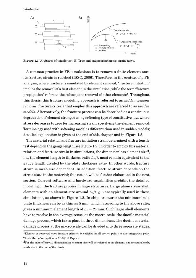
Figure 1.1. A) Stages of tensile test. B) True and engineering stress-strain curve.
A common practice in FE simulations is to remove a finite element onceits fracture strain is reached (ISSC, 2006). Therefore, in the context of a FEanalysis, where fracture is simulated by element removal, “fracture initiation”implies the removal of a first element in the simulation, while the term “fracturepropagation” refers to the subsequent removal of other elements1. Throughoutthis thesis, this fracture modeling approach is referred to as sudden elementremoval; fracture criteria that employ this approach are referred to as suddenmodels. Alternatively, the fracture process can be described as a continuousdegradation of element strength using softening type of constitutive law, wherestress decreases to zero for increasing strain specifying the element removal.Terminology used with softening model is different than used in sudden models;detailed explanation is given at the end of this chapter and in Figure 1.5.
The material relation and fracture initiation strain determined with a tensiletest depend on the gauge length; see Figure 1.2. In order to employ this materialrelation and fracture strain in simulations, the dimensionless element size2,i.e., the element length to thickness ratio Le/t, must remain equivalent to thegauge length divided by the plate thickness ratio. In other words, fracturestrain is mesh size dependent. In addition, fracture strain depends on thestress state in the material; this notion will be further elaborated in the nextsection. Current software and hardware capabilities prohibit the detailedmodeling of the fracture process in large structures. Large plane stress shellelements with an element size around Le/t ≥ 5 are typically used in thesesimulations, as shown in Figure 1.2. In ship structures the minimum ruleplate thickness can be as thin as 5 mm, which, according to the above ratio,gives a minimum element length of Le = 25 mm. Such large shell elementshave to resolve in the average sense, at the macro-scale, the ductile materialdamage process, which takes place in three dimensions. The ductile materialdamage process at the macro-scale can be divided into three separate stages:
1Element is removed when fracture criterion is satisfied in all section points at any integration point.
This is the default option in ABAQUS Explicit.2For the sake of brevity, dimensionless element size will be referred to as element size or equivalently,
mesh size in the rest of the thesis.
14

Introduction
necking, fracture initiation, and fracture propagation. Because of dependenceof fracture initiation strain on mesh size the material relation and fractureinitiation strain determined experimentally with test specimens are not directlyapplicable to simulation of large structures. The question arises as to how todetermine the structural response using large shell elements, without losingdetails of the material damage process observed in test specimens.
ScaleSmall test specimen Stiffened panel Large ship structure
Le < 1 mm, t = 1 - 20 mm
11
22
21
12
11
22
33
3132
23
2112
13
Le
t
True
stre
ss
Plastic strain
Gauge length
Le/t
Le > 10 mm, t = 5-100 mmLe/t
f
Figure 1.2. Illustration of the different scales in fracture analysis: small test specimen, stiffenedpanel and large-scale ship structure.
Different approaches exist to overcome the scale issue, but the damage me-chanics behind those approaches has often been overlooked. Consequently,there is considerable uncertainty in different fracture criteria, especially onhow they account for the mesh size dependence and stress state. In this thesis,a systematic approach is proposed to determine the fracture initiation strainand the equivalent plane stress material curve for different element sizes andstress states. This equivalent material curve is further extended to representthe whole damage process of the material, including necking, fracture initiationand propagation, in a single large shell element. The impact on prediction ofstructural behavior of large structures is presented, and suggestions for futurework are given.
1.2 State of the art
Ductile fracture of metals is a complicated process and requires detailed in-vestigations of the microstructure of the material (Woelke and Abboud, 2012).Fracture process in the microstructural level involves nucleation, growth andcoalescence of voids (Garrison and Moody, 1987; Tasan et al., 2009; Benzergaand Leblond, 2010). Growth and coalescence can be investigated using unit cellmodels where the scale of the analyzed problem is consistent with the grain
15
Introduction
size (Gurson, 1977; Barsoum and Faleskog, 2007; Dunand and Mohr, 2014;Tvergaard, 2014). In the analysis of large engineering structures the rangeof scale is several orders of magnitudes higher, which makes the use of thesemodels prohibitive because of the computational reasons.
One approach to upscale the non-linear behaviour of a well-characterized mi-crostructure is to employ multi-scale methods, and in particular computationalhomogenization (Coenen et al., 2012). However, this technique is computation-ally expensive, requires a well-defined microstructure as well as prematureknowledge of the crack path (Geers et al., 2010). In recent years, the conceptof a cohesive zone ahead of the crack tip generalized as cohesive zone models,introduced by Dugdale (1960) and Barenblatt (1962), have been used for crackpropagation problems. In this modeling approach special interface elementsobeying a cohesive law are introduced between the standard finite elementsallowing for inter-element separation. The practical applications of cohesivezone models however, are still limited to problems where the crack path isknown a priori; for example, welded structures (Schreider and Brocks, 2006)and post-mortem analysis of panels (Nielsen and Hutchinson, 2012; Woelke etal., 2013). The fact that crack path must be known a priori make these methodsunsuitable for design analysis of large structures such as ship, as ships containnumerous discontinuous structural elements, can experience variety of loadssimultaneously and have welds – all affecting the crack path.
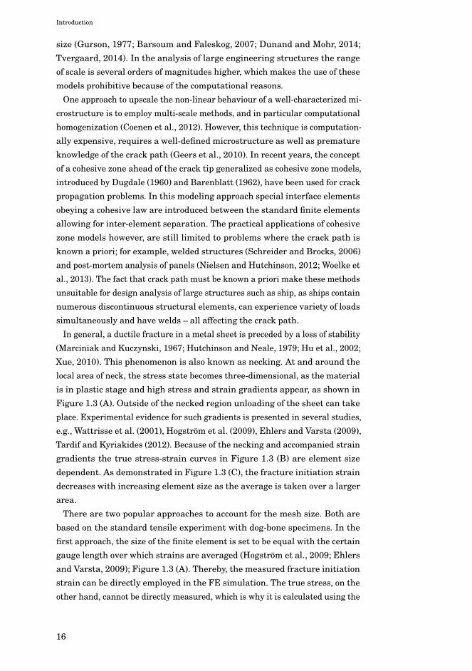
In general, a ductile fracture in a metal sheet is preceded by a loss of stability(Marciniak and Kuczynski, 1967; Hutchinson and Neale, 1979; Hu et al., 2002;Xue, 2010). This phenomenon is also known as necking. At and around thelocal area of neck, the stress state becomes three-dimensional, as the materialis in plastic stage and high stress and strain gradients appear, as shown inFigure 1.3 (A). Outside of the necked region unloading of the sheet can takeplace. Experimental evidence for such gradients is presented in several studies,e.g., Wattrisse et al. (2001), Hogström et al. (2009), Ehlers and Varsta (2009),Tardif and Kyriakides (2012). Because of the necking and accompanied straingradients the true stress-strain curves in Figure 1.3 (B) are element sizedependent. As demonstrated in Figure 1.3 (C), the fracture initiation straindecreases with increasing element size as the average is taken over a largerarea.
There are two popular approaches to account for the mesh size. Both arebased on the standard tensile experiment with dog-bone specimens. In thefirst approach, the size of the finite element is set to be equal with the certaingauge length over which strains are averaged (Hogström et al., 2009; Ehlersand Varsta, 2009); Figure 1.3 (A). Thereby, the measured fracture initiationstrain can be directly employed in the FE simulation. The true stress, on theother hand, cannot be directly measured, which is why it is calculated using the
16

Introduction
x
P / A ln(1 )
0
L0
L
PA0
A
t
F / A0
L L0
LFractureNecking
Engineering stress-strain
True stress-strain
Stre
ss
Strain
Frac
ture
stra
in
A)
B) C)
Strain gradients
Post-necking
Finite elements
Gauge length
Figure 1.3. Origin of size effects. A) Standard tensile test. B) Engineering and true stress-straincurves. C) Dependence of fracture strain on finite element size – Barba’s law.
minimum cross-sectional area of the specimen3. The alternative, an iterativeapproach, focusses on accurate prediction of fracture initiation strain only. Forone selected element size, agreement between the numerical simulation and thetensile experiment is achieved by iteratively changing the fracture initiationstrain until compliance between simulation and experiment is achieved; see,e.g., Zhang et al. (1999), and Simonsen and Lauridsen (2000). As a result, thetrue stress-strain relation until the point of fracture initiation is obtained forlarger elements, as shown in Figure 1.3 (B). Both approaches can be used fordifferent element sizes, yielding a relation displayed in Figure 1.3 (C), whichprescribes how to scale the fracture strain according to the element size Le/t.This scaling law derived on the basis of a uniaxial tension test is known asBarba’s law. The fracture criterion that is based on the critical equivalent plasticstrain and is scaled with Barba’s law is referred as the shear4 criterion. Thesimplicity of the shear criterion stems from the assumption that the stress statein the material has no effect on the scaled fracture initiation strain. Because ofits simplicity, this is one of the most frequently employed fracture criterion inship collision and grounding analysis, see the review article by Samuelides(2012) and the recent proceedings of the International Conference on Collisionand Grounding of Ships and Offshore Structures (Amdahl et al., 2013).
The commonly applied shear criterion and the scaling procedure in the formof Barba’s law are valid only under uniaxial tension. However, in structures
3Hogström et al. (2009) measured this minimum cross-sectional area at the fracture location while
Ehlers and Varsta (2009) measured it as a function of the gauge length.4The name shear stems from the fact that the von Mises equivalent plastic strain is used, whereas the
von Mises yield criterion is based on the critical shear strain energy at the tensile yield point (Rees, 2006)
17

Introduction
the stress state can deviate from uniaxial tension as a result of the chang-ing load conditions and structural topologies, e.g., a stiffened plate. Undermulti-axial stressing, fracture ductility depends markedly on the hydrostaticstress (σh = (σ1 + σ2 + σ3)/3; where σ1, σ2 and σ3 are the principal stresses)or the stress triaxiality η (hydrostatic stress divided by the equivalent vonMises stress σ =
√3J2, where J2 is the second invariant of the deviatoric stress
tensor) as first observed by McClintock (1968), Rice and Tracey (1969), andJohnson and Cook (1985) and more recently shown in various experimentalstudies, e.g., Bao and Wierzbicki (2004), Wierzbicki et al. (2005), Barsoum andFaleskog (2007), Choung et al. (2012), and Haltom et al. (2013). An exampleof the influence of triaxiality on the fracture initiation strain in plane stresscondition is shown for steel in Figure 1.4 (A) (Bai and Wierzbicki, 2010). Figure1.4 (B) shows the stress states considered in this thesis. Plane strain tensionarises as a special case for these shell elements in direction 1 (σ3 = 0 and ε1 = 0),as opposed to through thickness direction commonly assumed (direction 3, ε3 =0), see Bai (2008). Similar relationships have been presented for other metals,e.g. aluminum (Lou et al., 2012). This curve applies to a local scale, i.e., Le/t <
1, and is obtained through extensive experimental numerical study. From thelist of important features displayed in Figure 1.4 (A) one is highlighted: fractureductility is lowest in plane strain tension, η =
√1/3.
UAT
PST (in direction 1)
EBT
1
23
EBT, UAT,
PST,
A) B)
Figure 1.4. A) Influence of stress triaxiality on fracture initiation strain for TRIP steel (Bai andWierzbicki, 2010): uniaxial tension (UAT), plane strain tension (PST), equi-biaxialtension (EBT). B) Stress state extremes considered in detail in this thesis.
It is generally agreed that the shear criterion is appropriate for crash simula-tions of large structures, e.g., ships (Hogström and Ringsberg, 2012; Ehlers,2010), where the overall, or global, force-displacement response can be pre-dicted satisfactorily. This gives false confidence and disguises its accuracy forpredicting fracture with smaller elements, where Barba’s law scaling and shearcriterion have yielded inconsistent results (Alsos et al., 2009; Villavicencio etal., 2013).
The fracture criteria adopted by the Classification Societies are also stressstate independent. Det Norske Veritas (DNV, 2013) recommends a constant
18

Introduction
fracture initiation strain. Germanischer Lloyd (GL) uses a criterion that isvery similar to the shear criterion (Zhang et al., 2004; Scharrer et al., 2002)and where the critical thinning strain values are deduced from the thicknessmeasurements of a standard tensile test. To account for the mesh size effect thecriterion is scaled proportionally with the element size, Le/t.
Some of the fracture criteria employed in large-scale structural analysisrecognize the importance of stress triaxiality on the fracture initiation strain.One set of such criteria belongs to forming limit diagrams (FLD) that define thecritical strain or stress levels, which should not be exceeded in order to avoidthe localized necking and fracture of thin sheets. Since mesh size effect appearsafter necking, these criteria are often assumed to be mesh size independent,e.g., the Bressan-Williams-Hill (BWH) instability criterion (Alsos et al., 2008).Although this simplifies the implementation into FE codes, the approach hasbeen criticized because the post-necking energy under the stress-strain curve isneglected; see Figure 1.1. Hence, analyses with FLD (Hogström and Ringsberg,2012) and with the BWH criterion (Alsos et al., 2009) have yielded conservativeresults. To introduce mesh size sensitivity into analysis with FLD, Woelke andAbboud (2012) scale post-necking energy to fracture initiation linearly withelement size independently of the stress state; see also (Woelke et al., 2013).Another fracture criterion is the Rice-Tracey-Cockcroft-Latham (RTCL) damagecriterion (Urban, 2003; Törnqvist, 2003). The fracture initiation strain givenby the RTCL criterion is scaled for different element sizes on the basis of thefracture initiation strain determined with the uniaxial tension test, i.e., withBarba’s law.
Although the above-mentioned criteria are stress state dependent and hencemore advanced than the shear criterion, the mesh size effect is accounted for onthe basis of the uniaxial tensile test. However, besides the clear influence ofstress triaxiality on the fracture strain, it can similarly affect the scaling law,which is not considered by these criteria. In other words, the mesh size effectmight be affected by the stress state, which in turn would make Barba’s lawscaling inapplicable to other stress states besides uniaxial tension. Walters(2014) has proposed scaling the fracture initiation strain on the basis of boththe element size and stress triaxiality. He combines two well-known failurecriteria for small and large elements. As a lower bound of the failure criteriahe uses Swift’s (1952) necking criterion; this is used for high Le/t-ratios. Theupper bound is Bai and Wierzbicki’s (2010) failure criterion. In between theseextremes he scales the fracture strain according to the element size Le/t andstress triaxiality η. However, no physical justification for this approach is given.
When the element in the simulation satisfies the fracture criterion and isremoved from the simulation, the load carried by this element is redistributedto the neighboring elements. Consequently, fracture propagation is a discontinu-
19

Introduction
Defined with damage pararameters
Sudden Sudden model
True
stre
ss
Plastic strain
Softening
Softening modelDamage initiation
Element removal
Damage initiation
Element removal
Fracture initiation
necking, initiation and propagation
A) B) FE interpretation
Physical phenomena to be captured
Figure 1.5. A) Sudden versus softening type of equivalent material model for shell elements.B) Terminology used in this thesis to distinguish between different models.
ous process when the standard hardening type of material relation is used – seeFigure 1.2 – since load-carrying element is removed suddenly at the maximumstress. This is especially true when elements become large, Le/t > 10. Theproblem is partly solved by coupling the material model with the fracture model.Essentially, a softening type of true stress and strain relation is introduced, asillustrated in Figure 1.5 (A), which allows the element stiffness to be reducedgradually (Lemaitre, 1985; Lemaitre, 1996). With continuous degradation ofelement stiffness, or softening, an attempt is made to phenomenologically modelmaterial damage process and its stages with large shell elements, i.e., necking,fracture initiation and propagation. As a result of softening the load will beredistributed in a smoother manner, thus removing the discontinuity of theprocess; terminology used in this thesis to distinguish between the suddenand softening model is presented in Figure 1.5 (B). Term damage initiation isused in the context of softening model whereas fracture initiation is used in thecontext of sudden model. The approach is promising and has been employed byseveral authors (Hogström and Ringsberg, 2012; Woelke and Abboud, 2012;Woelke et al., 2013; AbuBakar and Dow, 2013), and in a slightly modified formby Marinatos and Samuelides (2013) who replaced the softening portion ofthe curve with a tangent type of curve or a power law curve5. However, theidentification of proper damage parameters which describe the softening processis a challenging task. For instance, all the authors rely on a uniaxial tensile testand assume that bifurcation from the standard true stress-strain curve occursonce the necking begins. This bifurcation point is denoted as “damage initiation”in Figure 1.5 (A). However, none of the authors describe how to account for theenergy under the softening curve beyond damage initiation. Therefore, therelevant parameters that define the softening law in Figure 1.5 (A) remainunclear.5Hogström and Ringsberg (2012), and AbuBakar and Dow (2013) both used an ABAQUS relative dis-
placement approach to model damage-induced softening. Woelke and Abboud (2012), and Marinatos and
Samuelides (2013) both wrote their own constitutive model.
20

Introduction
1.3 Scope of work
This thesis enhances the fracture modeling of large-scale metal sheets withfinite element method. The behavior of shell elements is considered in associa-tion with the fracture criterion that triggers their removal from the simulation.The emphasis is placed on the following aspects:
• mesh size dependence of the fracture initiation strain under multi-axialstress states;
• softening of the stress-strain curve due to necking, initiation and propaga-tion of fracture;
• practical engineering point-of-view towards simulation of damage in shipstructures.
Thus, a holistic view is taken of the fracture process, in which the fractureinitiation strain depends on both the element size and the stress state in thematerial. Furthermore, to account for the other two stages of the materialdamage process, preceding necking of the material and following fracturepropagation, a softening type of material relation is used. The outline of theinvestigation is presented in Figure 1.6.
In PI, material behavior before fracture initiation is investigated at a lo-cal scale considering pure membrane action and neglecting bending. Thisinvestigation is carried out for stress states of uniaxial (UAT), plane strain(PST), and equi-biaxial tension (EBT). Different stress states were consideredsince the intensity of the stress and strain gradients, and thus the severityof the mesh size effect, might depend on the stress state in the material. Thephenomena that are observed are transferred onto a large scale using theconcept of an averaging unit (AU). In other words, a method is proposed todetermine the fracture initiation strain for sudden fracture model for large shellelements subject to various stress states. In PII softening model is introduced,fracture propagation in AU is analyzed and damage parameters for large shellelements are identified for the Mode I tearing case. In addition, softening modelis implemented into the commercial code ABAQUS as a user-defined materialsubroutine. In PIII ductile fracture in stiffened and unstiffened panels in anidealized ship collision event is simulated using the sudden and softeningmodel and a comparison with the existing fracture criteria is presented. InPIV the developed approach is applied to an optimized ship side structure forselected collision scenario and a comparison is made with some of the existingfracture criteria and between various mesh sizes. This illustrates the influenceof the present approach on the crashworthiness predictions. PV investigatesthe relevant failure modes and collapse mechanisms of novel crashworthystructures, such as steel sandwich panels (Allen, 1969; Rubino et al., 2008). In
21

Introduction
Le/t < 1
Le/t > 10
Element size [-]
Fracture strain [-]
Stress triaxiality, 0 1/3 2/3
Multiaxial tension
Barba’s law
UAT, EBT,
PST, 3Figure 1.4
Component [PIII]
Traditional ship structurebuilt from stiffened panels [PIV]
[P1]
PIPII
Sudden
Element removal
True
stre
ss
True strain
Necking
Initiation
Propagation
Initiation
Propagation
Softening
Crashworthy sandwich panels [PV]
Multiaxialtension
Traditional shibuilt from stiffe
[P1]
Crashwoip structureened panels [PIV]
ApplicabilityInfluence
Figure 1.6. Outline of the investigation
these structures, energy is mostly absorbed by bending due to buckling andfolding mechanisms, instead of fracture and tearing. This perspective bringsout the limitations of the present fracture modeling approach, and thus, setsdirections for future work.
1.4 Limitations
Numerical fracture simulations are challenging because of the vast numberof parameters affecting the analysis (Jones, 1983; Jones, 2013), uncertaintiesin the input parameters (Hogström and Ringsberg, 2012; Wisniewski andKołakowski, 2003), and the paucity of the experimental data. It is the analyst’stask to identify important features of the physical phenomenon and simplifythe problem accordingly. The limitations and simplifications adopted in thisthesis are described below.
Ship collision and grounding accidents typically occur at low speeds so theycan be considered quasi-static in nature. Therefore, all deformation processesare treated as quasi-static and the material strain-rate effects can be neglectedin the analysis.
The presented approach is applicable to fracture initiation and tearing inshell elements under membrane action and out-of-plane bending is neglected.Thus, through thickness strain gradients associated with shell element bendingdeformations are omitted as they are considered negligible in comparison with
22

Introduction
membrane strains in large-deformation theory where deflections are larger than0.5t (Timoshenko and Woinowsky-Krieger, 1959). This limitation is justified asfar as fracture in large crash simulations occur primarily under membraneloading.
Only the behavior of the basic plate and stiffener material, not that of thewelded material, is considered. This is justified since the base plate tearingis a relevant failure mode during a collision or grounding event (Wang et al.,2000). Furthermore, only the behavior of steel material in room temperature isconsidered in this thesis.
23

Introduction
24

2. Fracture modeling
2.1 Scaling of fracture initiation strain for multi-axial tension
In PI a numerical method was established to determine the fracture initiationstrain and the “equivalent plane stress” material curve for large shell elementsunder multi-axial stress states. First, necking and fracture initiation weresimulated with the fine solid element model under three different stress states:uniaxial tension (UAT), plane strain tension (PST), and equi-biaxial tension(EBT). Different stress states were considered since the intensity of the stressand strain gradients, and thus the severity of the mesh size effect, dependson the stress state in the material. The fine mesh solid element simulationsemployed the true stress-strain relation determined with experiments, thefracture initiation strain dependent on stress triaxiality, and the von Misesflow rule. These simulations provided the local response of the material in thelocalization zone that enabled the analysis of the stress state in the material,besides the strain state. To determine the size effect, fracture initiation strain,and equivalent plane stress material curve for large shell elements volumeaveraging was used. Hence, the local material response determined with severalsmall solid elements (Le/t < 0.2) was averaged over a predefined volume. Thesize (Le/t ratio) of this averaging volume was equivalent to that of large shellelements. Through-thickness volume averaging was justified, as the thicknessdirectional strain gradient was small in solid element simulations. This aver-aging volume is denoted as averaging unit (AU). Two different AU sizes wereconsidered in order to study the effect of the mesh size on the fracture initiationstrain and material curve. A distinctive feature of this upscaling method isits ability to predict the mesh dependency of the fracture initiation strainat different stress states – an important advantage over the state-of-the-artmethods (Zhang et al., 1999; Simonsen and Lauridsen, 2000; Hogström et al.,2009; Ehlers and Varsta, 2009).
PI showed that the fracture initiation strain depends on the size of the aver-aging unit, or, effectively, on the mesh size, as well as on the stress state. Inuniaxial tension the mesh size dependence is much stronger than that observedin the plane strain and equi-biaxial tension; see Figure 2.1. This proves that aBarba’s law type of fracture initiation strain scaling is only valid for uniaxial
25

Fracture modeling
UAT PST
EBT
60%
68%
~45%
~12%
0.35 0.4 0.45 0.5 0.55 0.6 0.65 0.70
0.2
0.4
0.6
0.8
1
1.2
Average stress triaxiality, a
L/t = 0.2L/t = 6L/t = 10
Figure 2.1. Results of PI. Mesh size effect in uniaxial tension (UAT) is much stronger than inplane strain tension (PST) and equi-biaxial tension (EBT).
tension. Therefore, the fracture initiation strain must be scaled on the basis ofelement size, as well as on the stress state.
Such a scaling framework was proposed by Walters (2014), who combined theclosed-form necking criterion by Swift (1952) and fracture criterion applicableto small plane stress shell elements (Bai and Wierzbicki, 2010). The approachin PI delivered a generic numerical approach to obtain mesh size dependentfracture initiation strain for different stress states and justified Walters (2014)scaling framework. Thus, this scaling approach was employed in PIII. Thisrequired a calibration of stress state dependent fracture criterion applicable tosmall plane stress shell elements. In PIII this calibration based on the uniaxialtension test was presented, see Figure 2.2 and PIII for details.
a
f [-
]
0.3 0.35 0.4 0.45 0.5 0.55 0.6 0.650
0.2
0.4
0.6
0.8
1
1.2
Fix the initial shape of the locus (based on Fig. 1.4 (A))
Take the fracture strain for L/t = 1 (small elements) in uniaxial tension
Shift the fracture locus to point
Fix the shape
Obtained fracture criterionfor small shells
Figure 2.2. Calibration of fracture criterion for small shell elements based on uniaxial tensiontest.
Walters (2014) approach gives fracture initiation strain as a function ofelement size and stress triaxiality, i.e. εf (Le/t, η), Figure 2.3 (A). Note how theshape of the fracture locus in Figure 2.3 (A) straightens when moving fromthe small scale (Le/t = 1) to the large scale (Le/t = 8). Consequently, the shearcriterion, which gives the correct fracture initiation strain at a small scale onlyat two discrete points, provides a good estimate for the fracture initiation strain
26

Fracture modeling
at a macro scale in the range between uniaxial and plane strain tension. Inother words, a stress state that strongly affects the fracture initiation strain insmaller elements has an almost negligible effect on the fracture initiation strainin large shell elements. With regard to large-scale collision simulations, this isan important result, which gives confidence in one of the most often used shearcriterion for predicting fracture initiation. Using the scaling approach presentedin Figure 2.3 (A) and by keeping the stress triaxiality constant, fracture straincan be plotted as a function of element size for different stress states. Figure 2.3(B) shows similarly to Figure 2.1 how mesh size effect depends on the stressstate.
a
f [-
]
B)A)
L/t = 2
L/t = 1
SwiftL/t = 8
= 1/3 = 3 = 2/3
Shear
0.3 0.35 0.4 0.45 0.5 0.55 0.6 0.650
0.2
0.4
0.6
0.8
1
1.2
f [-
]
a = 2/3EBT
a = 1/3UAT
a = 3PST
0 2 4 6 8 100
0.2
0.4
0.6
0.8
1
Figure 2.3. A) Scaling employed in PIII compared with shear criterion scaled with Barba’slaw. B) Mesh size dependence at stress states corresponding to multi-axial tension(Figure from PIII).
2.2 Damage-induced softening
PI also concluded that that the macroscopic true stress and strain relation inthe case of uni-axial tension softens considerably prior to fracture initiation.The softening phenomenon was associated with the unloading of the specimenbeyond through the thickness necking. In the plane strain state the softeningwas much weaker and in equi-biaxial tension no softening was found. It wasconcluded that the material relations obtained and the softening phenomenonobserved are only valid until fracture initiation. Therefore, in PII the damageprocess and softening were investigated further and the softening model forlarge shell elements was devised.
2.2.1 Damage parameters
The damage parameters that define the shape of the softening material behaviorwere identified using the concept of a representative volume element (RVE)6 inPII. The large-scale Mode I type of tearing experiment (crack propagates as a
6In the context of this thesis the concept of the RVE is equivalent to the concept of the averaging unit
(AU) introduced in PI.
27

Fracture modeling
result of in-plane bending) previously carried out by Simonsen and Törnqvist(2004) was simulated using fine solid elements; see Figure 2.4 (A). The RVEwas mapped to the crack path in the fine solid model in such a way that thecrack propagated through the RVE. During the crack propagation the strainenergy density in the RVE was recorded. In parallel, simulations were carriedout using large shell elements, and the size of the elements was equal to thesize of the RVE: Le/t = 2, 6, and 10. The damage parameters were identifiedusing an iterative approach. The assumption was that the fine solid elementmodel correctly predicts the strain energy density for propagating cracks. Thisstrain energy density was averaged over the RVE. The damage parameters ofthe softening model were iterated manually until the strain energy densitydistribution in large shell element corresponded to the one averaged over theRVE. The principle used for comparing the solid and shell results in the RVE isillustrated in Figure 2.4 (B).
RVEIncoming crack
1. Average over RVE at , and .2. Compare with shell model results
Le
Le
Shell element
A) B)
Figure 2.4. A) Mode I tearing of a large plate. Figure from (Simonsen and Törnqvist, 2004) B)Principle used for comparing the solid and shell results in the RVE at differentsteps.
2.2.2 Softening model
A two-stage softening model was proposed in PII to explicitly account for thenecking, crack initiation, and propagation; see Figure 2.5 (A). A two-stage modelpermits a full control over the shape of the softening curve and was thereforesuitable for a parametric study. However, the parametric study showed that thedamage process of large shell elements from necking until complete failure –steps � until � in Figure 2.4 (B) – can be successfully captured using only onesoftening stage, as shown in Figure 2.5 (B). That is, there is no need to split thesoftening process into two separate stages in such large-scale analysis. In thereduced model softening is induced by the damage D – a normalized quantity,which cannot be measured directly.
Damage is defined as
D =
∫ εf
0
dε
εf (ηa)(2.1)
where, εf (ηa) is the fracture locus in the space of equivalent plastic strain andaverage stress triaxiality, for instance, as shown in Figure 2.3 (B). Therefore,
28

Fracture modeling
damage is a normalized indicator, which reaches the value of one, D = 1, whenfracture initiates according to the fracture criterion. However, to account forthe fact that material deterioration begins at the necking stage, the damageinitiation parameter is set to be lower than one, D0 < 1. To account for thefracture propagation energy element is removed after fracture initiation accord-ing to critical damage parameter, Dc > 1. The shape of the softening curve iscontrolled by the parameter m, which controls the non-linearity of the process;for details, see PII.
Plastic strain
True
stre
ss
Damage initiationSudden model
Damage due tonecking
Damage due tocrack propagation
Fracture initiation
Element removal
1st stage 2nd stage
D0 < 1
D = 1
Dc > 1
Plastic strainTr
ue s
tress
Damage initiation
Sudden model
Softening model
Elementremoval
Fracture initiation(As defined in [P1])
A B
Figure 2.5. A) Two-stage softening model. B) Reduced softening model suitable for Mode Itearing in PII.
2.2.3 Influence of softening on tearing
As demonstrated in Figure 2.5 (B), the element stiffness reduces gradually withsoftening, which in turn resulted in a smoother force-displacement curve forthe Mode I tearing problem. Although the smoother response provided by thesoftening model is physically more realistic, the plastic energy dissipated totear the panel was equally well captured by the shear criterion and suddenmodel. The shear criterion yields a good estimate for the plastic dissipationenergy for two reasons. First, it was previously calibrated by Simonsen andTörnqvist (2004) to fit the experimental results, and second, the stress stateduring tearing remains mostly constant.
The parametric study carried out in PII demonstrated that the amount of soft-ening depends on the mesh size; see Figure 2.6. This effect is clearly illustratedby the area ratio: the area under the non-softened portion of the curve to thearea under the softened portion. This ratio increases with decreasing elementsize indicating that softening loses its relevance in smaller elements. Indeed, asshown by Li and Wierzbicki (2010) and Gruben et al. (2012) softening in verysmall elements is only required to predict slant fracture. In the same context,the damage parameters that define the softened curve (damage initiation,critical damage, and shape) depend on the mesh size. For instance, to correctlycapture the plastic dissipation energy of the structure it is critical to define theaccurate value for the damage initiation parameter D0, as well as the critical
29

Fracture modeling
0 0.1 0.2 0.3 0.4 0.5 0.60
100
200
300
400
500
600
True
stre
ss [M
Pa]
Plastic strain [-]
Le = 50 mm3010
DcD0
0.9
1.51.6
D0=0.70.8
Dc=1.7
A1 A2
A1/A210 > 30 > 50
1.5
2
m=1.5
Figure 2.6. Softening models suitable for tearing simulations. Notice that the damage initiationparameter D0 and critical damage parameter Dc are element size dependent. Theshape parameter m remains constant for larger elements.
damage parameter Dc. In contrast, when damage parameters calibrated on thebasis of tensile tests were employed in tearing simulations (Hogström et al.,2009; AbuBakar and Dow, 2013), the plastic dissipation energy of the structureswas over- or underestimated, depending on the mesh size. With respect tostructural analysis, this is a very important result. It is further pointed out thatalthough the mesh size effect on the softening law is obvious, the results cannotexplain the influence of the stress state since it remained constant throughoutthe tearing process. The softening model presented is valid for Mode I tearingand therefore, the applicability of the present approach to actual structures isdiscussed in detail in the next chapter.
30

3. Influence on structural response
3.1 Stiffened and unstiffened panels
3.1.1 Experiments and FE analysis
To determine the influence of the findings from papers PI and PII on the finiteelement crashworthiness analysis, panel indentation simulations were carriedout in PIII. The influences of mesh size, stress states and softening on impactsimulations were studied. FE simulations were carried out with the stiffenedand unstiffened panels. Panels were experimentally tested (Alsos and Amdahl,2009) and later analyzed by Alsos et al. (2009) using BWH and RTCL damagecriteria. The experimental setup is shown in Figure 3.1. The FE models werediscretized with a wide range of element sizes ranging from Le/t = 1...20. Thefracture initiation strain was scaled on the basis of the stress state and elementsize according to Figure 2.3 (A)7. Softening was used in the context of the largestshell elements Le/t = 20 and the results were compared with the suddenmodel. The fracture criterion and softening were only defined for the plate sincefracture did not occur in the stiffener in the experiments. Simulations were alsocarried out with the shear fracture criterion adjusted for different element sizesaccording to Barba’s law.
3.1.2 Influence of mesh size on panel response and fractureprediction
Compared with the analysis carried out with the shear criterion and the resultsobtained by Alsos et al. (2009) with the RTCL criterion, the present scaling ap-proach delivered more accurate results regarding the measured and simulatedforce-displacement curves for a wide range of element sizes. The mesh sizedependency of the FE solution was reduced in comparison with other approachessince the stress state is considered in scaling the fracture initiation strain. Theshear and RTCL criteria could provide good agreement between the measured
7In the experiments the plate thickness in the panels was 5 mm; thus this thickness was also used in the
simulations. Although Figure 2.3 gives the fracture initiation strain as a function of the dimensionless
element size Le/t, the results presented in the following section will apply only to the plate thickness of
5 mm.
31

Influence on structural response
A)
B)
1FB
US
C)
Figure 3.1. A) Transverse and B) longitudinal cross-sections of the panels with and withoutstiffener. c) Experimental setup illustrating the equipment (rig, hydraulic jack andtest component). Figures from Alsos and Amdahl (2009).
A) L/t = 2 B) L/t = 4 C) L/t = 8
D D D
Figure 3.2. Contours of damage at the fracture location obtained with different mesh densities– US panel, [PIII]. A) Le/t = 2. B) Le/t = 4. C) Le/t = 8.
and simulated force-displacement curves for a specific element size. However,this accuracy was not preserved when the element size was changed. It is worthnoting that Alsos et al. (2009) also obtained mesh-independent results whenemploying the BWH criterion, but an unstiffened panel, for instance, failedearlier when this criterion was used.
Figure 3.2 presents the damage contours of the failed panels obtained with thepresent approach. In the test, the crack propagated in a direction that requiredthe lowest amount of energy, which had a trajectory of the circumference. Inspite of the rectangular mesh employed, current simulations can approximatethe annular crack path. The behavior is most accurately reproduced by thesmallest elements Le/t = 2 in Figure 3.2 (A), where the annular crack clearlyprevails. In simulations with larger elements Le/t = 4 and 8 the size of theelements and orthogonality of the mesh forces the crack to grow along a straightpath in the longitudinal direction of the panel. Eventually, the crack will turnbecause of the mechanics of the problem, but still prefers to propagate along astraight path. In the current case, crack propagating along a straight path willincrease the energy absorbed by the structure.
32

Influence on structural response
3.1.3 Influence of softening on panel response and fractureprediction
The panels carried loads primarily through membrane action, which led to asudden loss of stiffness once the failure happened. The resulting load drop wassteep and since the softening mostly affects the analysis beyond fracture initia-tion and during fracture propagation, it had a minor influence on the currentanalyses. Although the crack propagated in the experiments, the element sizein these simulations was so large that the whole force-displacement responsewas completely defined by the removal of a single large element; see Figure 3.3(B) and (C). Nevertheless, one difference between the sudden and softeningmodels was that the elements were kept longer in the simulation with softening;see, for example, the unstiffened panel results in Figure 3.3. Considering theseries of events taking place during the ship collision or grounding analysis,keeping elements in the analysis longer can affect the extent of the damage,the amount of water flowing in, and consequently the survivability of the ship(Spanos and Papanikolaou, 2011; Ringsberg, 2010).
A) B) C)
Figure 3.3. Unstiffened panel. A) Experiment (Alsos and Amdahl, 2009). B) Analysis resultswith softening model and C) sudden model. Damage contours are shown, [PIII].
Furthermore, the damage parameters calibrated in PII for the stable tearingprocess were modified to capture the experimental force-displacement curveand sudden force drop in panels after fracture initiation. In effect, the softeningpart of the material relation changed as shown in Figure 3.4. Note that inthe case of Mode I tearing the stress reduction was almost linear (m = 1.5),whereas in the panel simulations it is logarithmic (m = 3). In contrast, otherauthors have mainly used linear, m = 1 (AbuBakar and Dow, 2013; Hogströmand Ringsberg, 2012), or exponential stress reduction, m < 1 (Woelke andAbboud, 2012). Figure 3.4 reveals that in the panel indentation simulations(PIII) less softening was required than in the tearing simulations (PII). This isan important result given that the main aim of the softening is to correctlycapture the plastic dissipation energy of large shell elements during the damageprocess, whereas this damage process as shown depends on the failure modein tearing. Here, two contrasting failure modes are noted: a stable tearingprocess observed in PII versus the fracture initiation and sudden rupture of theplating accompanied by the significant load drop observed in PIII. Besides the
33

Influence on structural response
different failure modes, the stress state also varied between the two simulations:in the panel simulations the stress state was between the plane strain andequi-biaxial tension, while in the tearing simulations (PII) it was between theplane strain and uniaxial tension. This implies that the amount of softening isrelated to the stress state in the material. This is also supported by the resultsof PI, which showed that the damage-induced softening prior to initiation wasat its strongest in uniaxial tension.
D0=0.60.7
0.9
Dc=1.7
True
stre
ss [M
Pa]
Plastic strain [-]0 0.1 0.2 0.3 0.4 0.5 0.6
0
100
200
300
400
500
600
Tearing, Le=50 [P2]
Unstiffened panel, Le=100 [P3]Stiffened panel, Le=100 [P3]
m=1.5
m=3m=3
Dc=1.4
Figure 3.4. Amount of softening represented by the area under the softening portion of thecurve in different analysis.
3.1.4 Discussion on importance
Based on the FE tearing simulations carried out in PII and impact simulationscarried out in PIII the importance of softening is discussed in the contextof stiffened panel analysis. It is certainly attractive to phenomenologicallymodel necking, fracture initiation and propagation inside large shell elementswith softening. However, in some cases the difficulties related to calibration ofdamage parameters outweigh the benefits. Analyses show that the damageparameters depend on the stress state, failure mode (stable tearing vs. suddenfracture initiation) and mesh size, which makes the analysis overly complicatedfor practicing engineer. In contrast, traditional sudden model is shown to givereasonable results with different mesh densities (PIII) as far as the fractureinitiation strain is properly scaled on the basis of mesh size and stress state,Figure 2.3 (A).
3.2 Large-scale structures
3.2.1 Collision simulations with different criteria
Softening had a minor influence on the analysis results in the panel indentationsimulations. This was due to limited damage size and the fact that only one
34

Influence on structural response
0 5 10 15 200
0.1
0.2
0.3
0.4
0.5
0.6
0.7
Le/t
t=20 mmLe=50 mmLe=150 mmLe=300 mm
SHEAR
DNV
GL
f [-
]Figure 3.5. Fracture criteria employed.
large shell element was removed in the analysis. For this reason, the extentof the damage had to be increased to demonstrate the effect of softening onlarge-scale crash simulations. Therefore, in PIV collision simulations werecarried out with a ship side structure that had previously been optimized forcrashworthiness by Kõrgesaar and Ehlers (2010). In those simulations elementlength was 150 mm and approximately 500 shell elements were removed. Thestructure was analyzed with 3 different state-of-the-art fracture criteria (suddenmodels): the shear criterion, the DNV (2013) constant fracture initiation straincriterion, which is independent of the element size and stress state, and thecritical through thickness strain criterion referred to as GL (Zhang et al., 2004;Scharrer et al., 2002); see Figure 3.5. Additionally, the present approach wasused, in which the fracture initiation strain depends on both the mesh size andstress state according to Figure 2.3. With regard to the present approach, boththe sudden model and the softening model were employed. In simulations withsoftening model the same set of damage parameters was used as defined in PIIIfor the stiffened panel.
To determine how the criteria employed can handle the mesh size effectdifferent mesh sizes were considered. The effect of the mesh size on the crashand collapse analysis of large structures has been discussed by various authors,e.g., Amdahl and Kavlie (1992), Naar (2006), Paik (2007a), and Paik (2007b). Themesh size should be fine enough to capture the primary damage mechanismsobserved in ship collision analysis: membrane stretching, bending due to folding,and crushing of the main supporting members (Wang et al., 2000). Naar (2006)reports that to simulate collapse, at least four shell elements have to be usedfor plating between stiffeners, whereas Kitamura (2000) states that a 200-mmelement size is a standard for a side shell collision. Therefore, the structureswere discretized with three different element lengths at the collision location:50, 150, and 300 mm8, which resulted in ~14, ~5, and 2 elements between
8Here the elements are quoted by their length instead of their dimensionless size Le/t as the plate
thickness at the impact location varied from 20 mm to 28 mm.
35

Influence on structural response
the stiffeners, respectively. It is pointed out that 300-mm mesh was selecteddeliberately larger than suggested in the literature so as to test the limits of thepresent approach.
3.2.2 Comparison of different criteria
The plastic dissipation energy obtained with different criteria and mesh sizes ispresented in Figure 3.6. It was found that most of the elements fail in stressstates between uniaxial (η = 1/3) and plane strain tension (η = 1/
√3). As
shown in Figure 3.6 (A), the present approach with softening converges tothe same solution independent of whether 50 or 150 mm elements were used.This shows that softening is necessary to account for the mesh size effectin this particular case. In contrast, the mesh size effect is clearly present inthe 300-mm element solution, demonstrating once more that the amount ofsoftening is mesh size dependent. This coarse mesh cannot capture the platecollapse mechanism between the stiffeners nor the folding and tripping of thestiffeners. Such deficiencies and structural strengthening cannot be accountedfor even with the softening material curve devised to characterize the damageprocess of large shells from necking until complete failure, excluding othermechanisms such as bending. As a result, force-displacement curves obtainedwith 300 mm mesh displayed strong oscillations and were not informative.
The present approach without softening (Figure 3.6 (B)) does not show thesame convergence as obtained with softening: 150 mm solution is shown toabsorb more energy than 50 mm solution. It is pointed out that number ofelements that failed was the same in the analysis with and without softening.This suggests that in analysis without softening, fracture strain should havebeen even lower. Similar conclusion is appropriate also for the shear criterion,which overestimates the absorbed energy with 150 mm mesh in comparisonwith 50 mm mesh, see Figure 3.6 (C).
The DNV criterion, on the other hand, yielded a low scatter band between thedifferent mesh sizes, as evidenced in Figure 3.6 (D). However, this is attributedto the low fracture initiation strain value, as a result of which elements wereremoved before the mesh size effect settled in9. For the same reason, the dis-sipated plastic energy is the most conservative in comparison with the othercriteria, although the number of elements removed, for instance in the 150-mmmodel, was twice as high as that predicted with the present approach. Thissuggests that the extent of the damage is also considerably larger. At the sametime, the plastic dissipation energy obtained with the coarsest, 300 mm mesh,was closest to the reference solution (the present approach with softening,Le = 50 mm).
Figure 3.6 (E) shows that the GL criterion considers the mesh dependency
9It is reminded here that the FE solution becomes mesh size dependent beyond necking.
36

Influence on structural response
0 1 2 3 4 50
50
100
150
200
Pla
stic
dis
sipa
tion
ener
gy [M
J] A) Present approach (soft)
Present approach (soft)Le = 50 mm
B) Present approach
Displacement [m]
0 1 2 3 4 50
50
100
150
200
Pla
stic
dis
sipa
tion
ener
gy [M
J] D) DNV
Displacement [m]
0 1 2 3 4 50
50
100
150
200
Pla
stic
dis
sipa
tion
ener
gy [M
J]
Displacement [m]
C) Shear
0 1 2 3 4 50
50
100
150
200
Pla
stic
dis
sipa
tion
ener
gy [M
J]
Displacement [m]
Le = 50 mmLe = 150 mmLe = 300 mm
Displacement [m]0 1 2 3 4 5
0
50
100
150
200
Pla
stic
dis
sipa
tion
ener
gy [M
J] E) GL
Present approach (soft)Le = 50 mm
Present approach (soft)Le = 50 mm
Present approach (soft)Le = 50 mm
REF.
F) 150 mm
DNVGL
Present approach (soft)
Present approachShear
0 1 2 3 4 50
50
100
150
200
Pla
stic
dis
sipa
tion
ener
gy [M
J]
Displacement [m]
Figure 3.6. Scatter band in plastic dissipation energy obtained with different fracture criteria.
effectively in both coarse mesh models, whereas the convergence compared withthe reference solution is very good. However, it was expected that less energywill be absorbed in comparison with the DNV criterion as the GL fracture strainis lower than that given by the DNV criterion, Figure 3.5. The low fractureinitiation strain explains why the mesh size effect did not appear in simulationswith GL and DNV criteria. However, to explain why more energy was dissipatedin the analysis compared with the DNV criterion a closer look was taken atthe failed elements. It was found that, compared with other criteria, fewerelements failed in stress states below a stress triaxiality η = 1/3 character-izing uniaxial tension. The reason is that thinning of the material is not adominant mechanism in η < 1/3, i.e., in shear and compression. Hence, thecritical thinning strain criterion cannot predict failure in this region. As aresult, since elements are not removed, the energy dissipated on deforming
37

Influence on structural response
them is significantly higher than in other cases. By coincidence, the plasticdissipation energy is similar to that obtained with the present approach withsoftening and the 50-mm model.
Figure 3.6 (F) compares the results obtained with different criteria and 150mm mesh. The present scaling approach (sudden model) provides an upperbound and DNV criterion a lower bound for the scatter band. The rest of thecriteria provide a comparable estimate for the plastic dissipation energy and interms of accuracy no preference between different criteria can be made.
3.2.3 Failure mechanisms in novel energy absorbing structures
Commonly, ship structures are built from stiffened panels. Large deflectionsin stiffened panels lead to situation where the membrane state dominatesover the bending. This makes the present approach developed for multi-axialtension suitable for stiffened panels, as shown in PIII and PIV where the meshsize dependency is removed to a better extent than with the state-of-the-artmethods.
However, in recent years novel crashworthy structures, such as various sand-wich panels, have been proposed where the majority of the impact energy isabsorbed through in-plane stretching, plastic hinge formation and folding toavoid early-stage rupture (Naar et al., 2002; Klanac et al., 2005; Pedersenet al., 2006; Karlsson, 2009). These bending-governed structures are moreefficient in spreading the impact load over a wider area. In PV it was shown thatoptimal core geometry could further increase the energy-absorbing capabilitiesof these structures without the weight penalty. The main finding was that it isdesirable to initiate early-stage buckling and plastic hinge formation in the coreto allow load redistribution into adjacent structural members. This leads to asofter response compared with stiffened panels. Therefore, the key differencecompared with stiffened panels is that most of the impact energy is absorbedthrough crushing (folding and buckling) of the core as shown in Figure 3.7 (A),as opposed to fracture and tearing. To capture these mechanisms in the core arelatively fine mesh is needed, as large shells cannot model such complicated
Elements removed to show the core
A) B)
Face plate and coreintersection
Fracture location
Figure 3.7. A) Deformation mechanism in optimized X-core sandwich panel. B) Picture of thefailed laser weld in the X-core sandwich panel. Figure from Ehlers et al. (2012).
38

Influence on structural response
deformation modes. Moreover, the fracture takes place in the vicinity of theintersection between the face plates and core, Figure 3.7 (A). In real structureswelds are located at these intersections. Such failure mode along longitudinalwelds was also reported by Ehlers et al. (2012), see Figure 3.7 (B). The presentapproach however, is validated for the base plate material. Furthermore, suchjoint-failure includes local out-of-plane bending and thus, through thicknessstrain gradients. Because of these reasons the applications of the approachesthat neglect strain gradients due to bending to structures where the bendingoccurs in the vicinity of welds is questionable; such structures are for examplethe steel sandwich panels [PV].
39

Influence on structural response
40

4. Concluding remarks
There were two main aims in this thesis. First, to understand the damage pro-cess of large shell elements considering the phenomena observed in small-scaletest specimens such as necking, consequential softening and ultimate ductilefracture. Second, to explore a rational and practical way to simulate the damageof ship structures using large shell elements. Until now, the influence of suchlocal phenomena on the behavior of large shell elements has not been explicitlyanalyzed. The damage process of shell elements was divided into three stages:necking, fracture initiation, and fracture propagation. A softening type of truestress and strain curve was used in order to describe the macroscopic responseof large shell elements. The approach presented was compared against otherstate-of-the-art methods in sample simulations of panel indentation tests andship collisions.
In PI a numerical method was developed that defines the equivalent planestress material curve until fracture initiation strain for large shell elementsunder multi-axial tension. It was found that the fracture initiation strainscales according to the stress state. The results show that the stress state hasonly minor influence on the fracture initiation strain of large shell elements,especially between the uniaxial and plane strain tension. The importance ofthis finding is emphasized due to the fact that elements failed mostly betweenthose two stress states in ship collision simulation [PIV]. In the context oflarge-scale crash simulations, the above result gives confidence in criteria thatneglect the stress state, e.g., the shear criterion. On the other hand, stressstate has a major influence on the fracture strain scaling. Significance of thisdiscovery is expected to increase over the coming years with ever increasingcomputational power that paves the way for exploiting finer meshes even invery large structures, such as ships.
Softening type of stress-strain curve was introduced in PII to phenomenolog-ically describe necking, fracture initiation and propagation with large shellelements under tension. Analyses with the softening model in PII showed that,in contrast to the sudden model, strain energy density distribution in the failingshell elements can be captured accurately. As indicated in PIV softening alsohelps to get better convergence with larger shell elements, i.e. remove mesh sizeeffect. However, it is very complicated to define proper calibration parameters apriori for real structures. Even for a simple tearing case under in-plane bending,calibration of parameters required several iterations (PII). These parameters
41
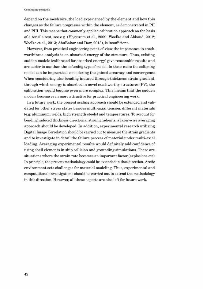
Concluding remarks
depend on the mesh size, the load experienced by the element and how thischanges as the failure progresses within the element, as demonstrated in PIIand PIII. This means that commonly applied calibration approach on the basisof a tensile test, see e.g. (Hogström et al., 2009; Woelke and Abboud, 2012;Woelke et al., 2013; AbuBakar and Dow, 2013), is insufficient.
However, from practical engineering point-of-view the importance in crash-worthiness analysis is on absorbed energy of the structure. Thus, existingsudden models (calibrated for absorbed energy) give reasonable results andare easier to use than the softening type of model. In these cases the softeningmodel can be impractical considering the gained accuracy and convergence.When considering also bending induced through-thickness strain gradient,through which energy is absorbed in novel crashworthy structures (PV), thecalibration would become even more complex. This means that the suddenmodels become even more attractive for practical engineering work.
In a future work, the present scaling approach should be extended and vali-dated for other stress states besides multi-axial tension, different materials(e.g. aluminum, welds, high strength steels) and temperatures. To account forbending induced thickness directional strain gradients, a layer-wise averagingapproach should be developed. In addition, experimental research utilizingDigital Image Correlation should be carried out to measure the strain gradientsand to investigate in detail the failure process of material under multi-axialloading. Averaging experimental results would definitely add confidence ofusing shell elements in ship collision and grounding simulations. There aresituations where the strain rate becomes an important factor (explosions etc).In principle, the present methodology could be extended in that direction. Arcticenvironment sets challenges for material modeling. Thus, experimental andcomputational investigations should be carried out to extend the methodologyin this direction. However, all these aspects are also left for future work.
42

Errata
Publication II
On p. 4 instead of Table 1 read Table 2
Publication III
On p. 14, Chapter 5, second paragraph: instead of Figs. 10(a) and 14(a) readFigs. 11(a) and 15(a). In Figure 17 a) the damage legends should be vice-versaas shown in manuscript Figure 3.3.
Publication IV
Two errors in captions to figures. Figure 9 should read Figure 10, and Figure 10should read Figure 11. Because of that, there are two errors in references tothe figures. On p.6, last paragraph: instead of Fig. 10 read Fig. 11. On p.7, lastparagraph of Chapter 6: instead of Fig. 8 (c) read Fig. 9(c).
43

Errata
44

Bibliography
ABAQUS, 2011. ABAQUS Analysis User’s Manual, Version 6.11, Dassault SystemesSimulia Corporation.
AbuBakar, A. and Dow, R.S., 2013. Simulation of ship grounding damage using thefinite element method. Int. J. Solids Struct., 50(5), pp. 623–636.
Allen, H.G., 1969. In: Analysis and Design of Structural Sandwich Panels PergamonPress, Oxford.
Alsos, H.S. and Amdahl, J., 2009. On the resistance to penetration of stiffened plates,Part I – Experiments. Int. J. Impact Eng., 36(6), pp. 799–807.
Alsos, H.S., Amdahl, J. and Hopperstad, O.S., 2009. On the resistance to penetrationof stiffened plates, Part II: Numerical analysis. Int. J. Impact Eng., 36(7), pp.875–887.
Alsos, H.S., Hopperstad, O.S., Törnqvist, R. and Amdahl, J., 2008. Analytical andnumerical analysis of sheet metal instability using a stress based criterion.Int. J. Solids Struct., 45(7-8), pp. 2042–2055.
Amdahl, J. and Kavlie, D., 1992. Experimental and numerical simulation of doublehull stranding, DNV – MIT Workshop.
Bai, Y. and Wierzbicki, T., 2010. Application of extended Mohr–Coulomb criterion toductile fracture. Int. J. Fract., 161(1), pp. 1–20.
Bai, Y., 2008. Effect of Loading History in Necking and Fracture. Thesis (Ph. D.).Massachusetts Institute of Technology, Dept. of Mechanical Engineering.
Bao, Y. and Wierzbicki, T., 2004. A Comparative Study on Various Ductile CrackFormation Criteria. J. Eng. Mater. Technol., 126(3), pp. 314-324.
Barenblatt, G.I., 1962. The mathematical theory of equilibrium cracks formed inbrittle fracture. Advances in Applied Mechanics. 7, pp. 55-129
Barsoum, I. and Faleskog, J., 2007. Rupture mechanisms in combined tension andshear—Experiments. Int. J. Solids Struct., 44(6), pp. 1768–1786.
Benzerga, A. and Leblond, J.-B., 2010. Ductile fracture by void growth to coalescence.Advances in applied Mechanics, 44, pp.169–305.
Choung, J., Shim, C.-S. and Song, H.-C., 2012. Estimation of failure strain of EH36high strength marine structural steel using average stress triaxiality. Mar.Struct., 29(1), pp. 1–21.
45

Bibliography
Coenen, E.W.C., Kouznetsova, V.G. and Geers, M.G.D., 2012. Multi-scale continu-ous–discontinuous framework for computational-homogenization–localization.J. Mech. Phys. Solids, 60(8), pp.1486–1507.
Det Norske Veritas, DNV-RP-C208: 2013. Determination of Structural Capacity byNon-linear FE Analysis Methods, pp. 1–66.
Dugdale, D.S., 1960. Yielding of steel sheets containing slits. J. Mech. Phys. Solids,8(2), pp.100–104.
Dunand, M. and Mohr, D., 2014. Effect of Lode parameter on plastic flow localizationafter proportional loading at low stress triaxialities. J. Mech. Phys. Solids,66(C), pp.133–153.
Ehlers, S., 2010. A procedure to optimize ship side structures for crashworthiness.Proceedings of the Institution of Mechanical Engineers, Part M: Journal ofEngineering for the Maritime Environment, 224(1), pp. 1–11.
Ehlers, S. and Varsta, P., 2009. Strain and stress relation for non-linear finiteelement simulations. Thin. Wall. Struct., 47(11), pp. 1203–1217.
Ehlers, S., Tabri, K., Romanoff, J. and Varsta, P., 2012. Numerical and experimentalinvestigation on the collision resistance of the X-core structure. Ships andOffshore Structures, 7(1), pp.21–29.
Garrison, W.M., Jr and Moody, N.R., 1987. Ductile fracture. Journal of Physics andChemistry of Solids, 48(11), pp.1035–1074.
Geers, M.G.D., Kouznetsova, V.G. and Brekelmans, W.A.M., 2010. Multi-scale com-putational homogenization: Trends and challenges. Journal of Computationaland Applied Mathematics, 234(7), pp.2175–2182.
Gruben, G., Hopperstad, O.S. and Børvik, T., 2012. Simulation of ductile crackpropagation in dual-phase steel. Int. J. Fract., 180(1), pp. 1–22.
Gurson, A.L., 1977. Continuum Theory of Ductile Rupture by Void Nucleation andGrowth: Part I—Yield Criteria and Flow Rules for Porous Ductile Media. J.Eng. Mater. Technol., 99(1), pp.2–15.
Haltom, S.S., Kyriakides, S. and Ravi-Chandar, K., 2013. Ductile failure undercombined shear and tension. Int. J. Solids Struct., 50(10), pp. 1507–1522.
Hogström, P. and Ringsberg, J.W., 2012. An extensive study of a ship’s survivabilityafter collision – A parameter study of material characteristics, non-linearFEA and damage stability analyses. Mar. Struct., 27(1), pp. 1–28.
Hogström, P., Ringsberg, J.W. and Johnson, E., 2009. An experimental and numericalstudy of the effects of length scale and strain state on the necking and fracturebehaviours in sheet metals. Int. J. Impact Eng., 36(10-11), pp. 1194–1203.
IMO (2006) Resolution MSC.216 (82) Adoption of Amendments to the InternationalConvention for the Safety of Life at Sea, 1974, as amended, December 8
46

Bibliography
ISSC, 2006. Report of committee V1: collision and grounding. In: P.A. Frieze, R.A.Shenoi, editors. Proceedings of the 16th International Ship and OffshoreStructures Congress, Southampton, UK.
Johnson, G.R. and Cook, W.H., 1985. Fracture characteristics of three metals sub-jected to various strains, strain rates, temperatures and pressures. Eng. Fract.Mech., 21(1), pp. 31–48.
Jones, N., 1983. Structural aspects of ship collisions. Structural crashworthiness,Chapter 11. Butterworth & Co (Publishers) Ltd.
Jones, N., 2013. The credibility of predictions for structural designs subjected tolarge dynamic loadings causing inelastic behaviour. Int. J. Impact Eng., 53,pp. 106–114.
Karlsson, U.B., 2009. Improved collision safety of ships by an intrusion-tolerantinner side shell. Marine Technology, 46(3), pp. 165–173.
Kitamura, O., 2000. Buffer Bow Design for the Improved Safety of Ships. Proceed-ings of the SSC/SNAME/ASNE Symposium, Society of Naval Architects andMarine Engineers.
Klanac, A. et al., 2005. Qualitative design assessment of crashworthy structures.Proceedings of the International Maritime Association of Mediterranean,Portugal, pp. 461–469.
Lemaitre, J., 1985. A Continuous Damage Mechanics Model for Ductile Fracture. J.Eng. Mater. Technol., 107(1), p.83.
Lemaitre, J., 1996. A Course on Damage Mechanics, Springer.
Li, Y. and Wierzbicki, T., 2010. Prediction of plane strain fracture of AHSS sheetswith post-initiation softening. Int. J. Solids Struct., 47(17), pp. 2316–2327.
Lou, Y., Huh, H., Lim, S. and Pack, K., 2012. New ductile fracture criterion forprediction of fracture forming limit diagrams of sheet metals. Int. J. SolidsStruct., 49(25), pp. 3605–3615.
Marinatos, J.N. and Samuelides, M., 2013. Material characterization and implemen-tation of the RTCL, BWH and SHEAR failure criteria to finite element codesfor the simulation of impacts on ship structures. J. Amdahl, S. Ehlers, and B.J. Leira, eds. Collision and Grounding of Ships and Offshore Structures. CRCPress, Trondheim, Norway, pp. 57–67.
McClintock, F.A., 1968. A criterion for ductile fracture by the growth of holes. J.Appl. Mech., 35, pp. 363–371.
Naar, H., 2006. Ultimate Strength Of Hull Girder For Passenger Ships. Doctoralthesis. Helsinki University of Technology.
Naar, H., Kujala, P., Simonsen, B.C. and Ludolphy, H., 2002. Comparison of thecrashworthiness of various bottom and side structures. Mar. Struct., 15(4), pp.443–460.
47

Bibliography
Nielsen, K.L. and Hutchinson, J.W., 2012. Cohesive traction-separation laws fortearing of ductile metal plates. Int. J. Impact Eng., 48(C), pp.15–23.
Paik, J.K., 2007a. Practical techniques for finite element modeling to simulatestructural crashworthiness in ship collisions and grounding (Part I: Theory).Ships and Offshore Structures, 2(1), pp. 69–80.
Paik, J.K., 2007b. Practical techniques for finite element modelling to simulate struc-tural crashworthiness in ship collisions and grounding (Part II: Verification).Ships and Offshore Structures, 2(1), pp. 81–85.
Pedersen, C.B.W., Deshpande, V.S. and Fleck, N.A., 2006. Compressive response ofthe Y-shaped sandwich core. Eur. J. Mech. A-Solid., 25(1), pp. 125–141.
Rees, D., 2006. Basic Engineering Plasticity: An Introduction with Engineering andManufacturing Applications 1st ed, Butterworth-Heinemann.
Rice, J.R. and Tracey, D.M., 1969. On the ductile enlargement of voids in triaxialstress fields*. J. Mech. Phys. Solids, 17(3), pp. 201–217.
Ringsberg, J.W., 2010. Characteristics of material, ship side structure response andship survivability in ship collisions. Ships and Offshore Structures, 5(1), pp.51–66.
Rubino, V., Deshpande, V.S. and Fleck, N.A., 2008. The collapse response of sandwichbeams with a Y-frame core subjected to distributed and local loading. Int. J.Mech. Sci., 50(2), pp.233–246.
Samuelides, M., 2012. Designing for protection against collision. C. Guedes Soares,Y. Garbatov, N. Fonseca, and A. P. Texeira, eds. Marine Technology andEngineering. pp. 955–977.
Scharrer, M., Zhang, L. and Egge, E.D., 2002. Collision calculations in naval designsystems, Report. Final report MTK0614 Nr. ESS2002.183, Version 1/2002-11-22, Germanischer Lloyd, Hamburg.
Scheider, I. and Brocks, W., 2006. Cohesive elements for thin-walled structures.Comp. Mater. Sci., 37(1-2), pp.101–109.
Simonsen, B.C. and Törnqvist, R., 2004. Experimental and numerical modelling ofductile crack propagation in large-scale shell structures. Mar. Struct., 17(1),pp. 1–27.
Simonsen, B.C. and Lauridsen, L.P., 2000. Energy absorption and ductile failurein metal sheets under lateral indentation by a sphere. Int. J. Impact Eng.,24(10), pp. 1017–1039.
Spanos, D.A. and Papanikolaou, A.D., 2011. On the time dependence of survivabilityof ROPAX ships. J Mar Sci Technol, 17(1), pp. 40–46.
Swift, H.W., 1952. Plastic instability under plane stress. J. Mech. Phys. Solids, 1(1),pp. 1–18.
48

Bibliography
Tardif, N. and Kyriakides, S., 2012. Determination of anisotropy and material hard-ening for aluminum sheet metal. Int. J. Solids Struct., 49(25), pp. 3496–3506.
Tasan, C.C., Hoefnagels, J.P.M., Horn, ten, C.H.L.J. and Geers, M.G.D., 2009. Exper-imental analysis of strain path dependent ductile damage mechanics andforming limits. Mechanics of Materials, 41(11), pp.1264–1276.
Timoshenko, S.P. and Woinowsky-Krieger, S., 1959. Theory of plates and shells, 2ndedition, McGraw-Hill, New York.
Tvergaard, V., 2015. Effect of initial void shape on ductile failure in a shear field.Mechanics of Materials, pp.1–8.
Törnqvist, R., 2003. Design of Crashworthy Ship Structures. Doctoral thesis. DTU.
Urban, J., 2003. Crushing and Fracture of Lightweight Structures. Doctoral thesis.Technical University of Denmark.
Villavicencio, R., Liu, B. and Soares, C.G., 2013. Response of a tanker side panelpunched by a knife edge indenter. J. Amdahl, S. Ehlers, and B. J. Leira,eds. Collision and Grounding of Ships and Offshore Structures. Trondheim,Norway, pp. 109–115.
Walters, C.L., 2014. Framework for adjusting for both stress triaxiality and meshsize effect for failure of metals in shell structures. Int. J. Crashworthines,19(1), pp. 1–12.
Wang, G., Arita, K. and Liu, D., 2000. Behavior of a double hull in a variety ofstranding or collision scenarios. Mar. Struct., 13(3), pp.147–187.
Wattrisse, B., Chrysochoos, A., Muracciole, J.-M. and Némoz-Gaillard, M., 2001.Kinematic manifestations of localisation phenomena in steels by digital imagecorrelation. Eur. J. Mech. A-Solid., 20(2), pp.189–211.
Wierzbicki, T., Bao, Y., Lee, Y.-W. and Bai, Y., 2005. Calibration and evaluation ofseven fracture models. Int. J. Mech. Sci., 47(4-5), pp.719–743.
Wisniewski, K. and Kołakowski, P., 2003. The effect of selected parameters on shipcollision results by dynamic FE simulations. Finite Elements in Analysis andDesign, 39(10), pp.985–1006.
Woelke, P.B. and Abboud, N.N., 2012. Modeling fracture in large scale shell structures.J. Mech. Phys. Solids, 60(12), pp. 2044–2063.
Woelke, P.B., Shields, M.D., Abboud, N.N. and Hutchinson, J.W., 2013. Simulationsof ductile fracture in an idealized ship grounding scenario using phenomeno-logical damage and cohesive zone models. Comp. Mater. Sci., 80, pp. 79–95.
Zhang, L., Egge, E.D. and Bruhms, H., 2004. Approval procedure concept for alter-native arrangements. Proceedings of the 3rd International Conference onCollision and Grounding of Ships (ICCGS2004), Izu, Japan.
49

Bibliography
50

9HSTFMG*agaiec+
ISBN 978-952-60-6084-2 (printed) ISBN 978-952-60-6085-9 (pdf) ISSN-L 1799-4934 ISSN 1799-4934 (printed) ISSN 1799-4942 (pdf) Aalto University School of Engineering Department of Applied Mechanics www.aalto.fi
BUSINESS + ECONOMY ART + DESIGN + ARCHITECTURE SCIENCE + TECHNOLOGY CROSSOVER DOCTORAL DISSERTATIONS
Aalto-D
D 2
2/2
015
Ship collisions and groundings are one of the greatest operational risks in maritime transportation. Regardless of continuous efforts to prevent these accidents, they will remain a serious threat. In order to minimize the consequences of such serious accidents engineers have to take into account the accidental loading in the design process. As a result of accidental loading, thin-walled ship structures fail due to fracture and tearing. This thesis investigates how to model these phenomena with finite element method and shell elements.
Mihkel K
õrgesaar M
odeling ductile fracture in ship structures with shell elem
ents A
alto U
nive
rsity
Department of Applied Mechanics
Modeling ductile fracture in ship structures with shell elements
Mihkel Kõrgesaar
DOCTORAL DISSERTATIONS