a14.7 – nm rothschild bank (ground investigation) (norwest ... · pdf filea14.7 –...
TRANSCRIPT

A14.7 – NM Rothschild Bank (Ground Investigation) (Norwest Holst Soil Engineering Ltd)


Project No: F15001 Document No. F01
NM ROTHSCHILD BANK LONDON EC4N
23/11/2007 Page 1 of 10
REPORT QUALITY ASSURANCE SHEET
Title:
REPORT ON A
GROUND INVESTIGATION
AT
NM ROTHSCHILD BANK
LONDON EC4N
Report Description: Date: Written By: Checked By: Approved By: Status:
Draft Factual 20/11/2007 H. Sydney J.T. Williams D.G. Harman
Final Factual 23/11/2007 H. Sydney J. T. Williams D.G. Harman
Distribution: Arup Geotechnics
:Internal Copy
The report is not to be used for contractual or engineering purposes unless this sheet is signed where indicated by both the originator of the report and the approver, and the report is designated “Final” on this report quality assurance sheet. Opinions and interpretations expressed in the report are outside the scope of UKAS accreditation. This report has been prepared for the sole internal use and reliance of the named Employer. This report should not be relied upon or transferred to any other parties without the express written authorisation of NHSED. If an unauthorised third party comes into possession of the report they rely on it at their peril and NHSED owes them no duty of care and skill.
Report Version No. SI FR 1.03 Issue Date 02/01/2007
Project No: F15001 Document No. F01
NM ROTHSCHILD BANK LONDON EC4N
23/11/2007 Page 2 of 10
GROUND INVESTIGATION: NM ROTHSCHILD BANK
REPORT CONTENTS
1.0 INTRODUCTION....................................................................................................................... 4
2.0 PURPOSE, SCOPE AND REPORT FORMAT................................................................................. 4 2.1 Purpose .....................................................................................................................................4 2.2 Scope of Work...........................................................................................................................4 2.3 Report Format...........................................................................................................................4 3.0 DESK STUDY INFORMATION.................................................................................................... 5 3.1 Scope of Study ..........................................................................................................................5 3.2 Site Location and Description...................................................................................................5 3.3 Geology.....................................................................................................................................5 4.0 FIELDWORK............................................................................................................................. 5 4.1 Scope of Fieldwork ...................................................................................................................5 4.2 Enabling Works .........................................................................................................................5 4.3 Cable Percussion Boreholes .....................................................................................................6 4.5 Trial Pits.....................................................................................................................................6 4.6 Survey .......................................................................................................................................7 4.7 Installations / Instrumentation ...............................................................................................7 4.8 Gas and Groundwater Monitoring ...........................................................................................7 5.0 LABORATORY TESTING............................................................................................................ 7 5.1 Scope of Testing .......................................................................................................................7 5.2 Geotechnical Soils Testing........................................................................................................7 5.3 Contamination Testing .............................................................................................................8 6.0 RESULTS OF THE INVESTIGATION............................................................................................. 8 6.1 Scope of Commentary..............................................................................................................8 6.2 Made Ground ............................................................................................................................8 6.3 River Terrace Deposits..............................................................................................................8 6.4 London Clay Formation ............................................................................................................9 6.5 Lambeth Group.........................................................................................................................9 6.6 Groundwater.............................................................................................................................9 REPORT REFERENCES.................................................................................................................... 10 LIST OF TABLES Table 1 Summary of Groundwater Inflows Recorded in Exploratory Holes Section B Table 2 Groundwater Level Readings for Exploratory Hole Installations Section B Table 3 Results of Gas Monitoring Section B
LIST OF FIGURES Figure 1 Site Location Plan Section D Figure 2 Exploratory Hole Location Plan Section D

Project No: F15001 Document No. F01
NM ROTHSCHILD BANK LONDON EC4N
23/11/2007 Page 3 of 10
GROUND INVESTIGATION: NM ROTHSCHILD BANK
REPORT CONTENTS (continued) SUPPORTING FACTUAL DATA SECTION A: NOTES ON FIELDWORK, LOGGING AND LABORATORY TESTING • Notes on Fieldwork Procedures • Terminology used in Soil Descriptions • Terminology used in the Description of Made Ground • Assessment of Aggressive Ground and Groundwater Conditions SECTION B: EXPLORATORY HOLE RECORDS AND FIELD DATA • Exploratory Hole Legend and Notation Sheet • Cable Percussion and Rotary Drilling Records • Inspection Pit/ Trial Pit/ Trial Trench records • Groundwater / Gas Monitoring / Sampling Results SECTION C: LABORATORY TEST RESULTS • Laboratory Test Data Key Sheet • Laboratory Test Summary Sheets (Soils) • Laboratory Test Data Sheets (Soils) • Contamination Test Sheets SECTION D: SITE PLANS • Site Location Plan • Exploratory Hole Location Plan SECTION E: PHOTOGRAPHS • Trial Pit Photographs

Project No: F15001 Document No. F01
NM ROTHSCHILD BANK LONDON EC4N
23/11/2007 Page 4 of 10
1.0 INTRODUCTION In August 2007 Norwest Holst Limited - Soil Engineering Division (NHSED) were instructed by Arup Geotechnics (The Engineer) acting for and on behalf of Stanhope Plc (The Employer) to carry out a ground investigation at N. M. Rothschild and Sons (NMR) Bank, in the City of London for the proposed development of the site. It is understood that it is proposed to replace the existing buildings with a fifteen storey building with two basement levels which are to be deeper than the existing ones below the present site. The investigation comprised the formation of one cable percussion borehole together with one trial pit. This factual report represents the results of the fieldwork and laboratory testing undertaken together with information on the ground and groundwater conditions encountered. The fieldwork was carried out in two phases; the first between 25th and 27th August 2007, and the second on 15th October 2007. 2.0 PURPOSE, SCOPE AND REPORT FORMAT 2.1 Purpose The purpose of this investigation was to determine the subsurface ground and groundwater conditions at the site of the proposed re-development. This information was to be obtained from a combination of intrusive investigation techniques and laboratory testing. 2.2 Scope of Work The brief for this factual report comprised the following items: 1. To form one exploratory hole on site. 2. To log and sample one trial pit on site. 3. To install gas and ground water monitoring instruments. 4. To monitor on site installations. 5. To undertake laboratory tests on samples recovered from exploratory holes. The sources of information used in the compilation of this report are detailed in the list of references on page 10. 2.3 Report Format This report is presented in the following format: Factual information comprising: - • Description of fieldwork • Exploratory hole logs • Laboratory test results • Maps and plans • Photographs of the trial pit

Project No: F15001 Document No. F01
NM ROTHSCHILD BANK LONDON EC4N
23/11/2007 Page 5 of 10
3.0 DESK STUDY INFORMATION 3.1 Scope of Study A formal comprehensive desk study was not requested by the Engineer for this investigation. The following sections however provide general details of site location and description and site geology as ascertained from published maps. 3.2 Site Location and Description The site is located at New Court and Nos 1 to 10 St Swithin’s Lane, City of London, EC4N, (approximate National Grid Reference TQ 327 810). The existing building is currently owned and occupied by the investment bank, N. M. Rothschild and Sons. At the time of the investigation the NMR Bank was bounded by The Wallbrook development to the south of the site (under construction at the time of the investigation); by 8-10 Mansion House Place, adjacent to the northern and western site boundary, (used by the British Arab Commercial Bank at the time of the investigation); by The Wallbrook Club, adjacent to the western boundary of New Court and by St. Swithin’s Lane, adjacent to the eastern site boundary. Ground levels varied around the perimeter of the site between approximately 14.0m OD at St Swithin’s Lane to 10.0m OD at Bond Court, with a slight downward gradient proceeding eastwards from the corner of Mansion House Place and St Swithin’s Lane. The area of open space between New Court and St Stephen’s Church was generally level. The location of the site is indicated on Figure 1 in Section D of this report. 3.3 Geology From the available information on the 1:50,000 scale Geological Survey map of the area (Sheet 256: 1993, Solid and Drift edition for North London) the site is shown to be underlain by River Terrace Deposits of Taplow Gravel and locally by alluvial drift deposits. These in turn overlie the London Clay Formation of Eocene age and at greater depth the Lambeth Group of Palaeocene age. 4.0 FIELDWORK 4.1 Scope of Fieldwork The scope of the fieldwork was specified by the Engineer and was undertaken in general accordance with BS 5930: 1999. In accordance with the specification and drawings provided by the Engineer, NHSED were required to survey the exploratory hole and to undertake the testing and sampling regime. One cable percussion borehole was formed by NHSED to a depth of 52.30m together with one trial pit formed by McGees (acting as subcontractors to Arup Geotechnics) to a depth of 2.03m. The exploratory hole locations are shown on the site plan presented in Section D of this report. 4.2 Enabling Works Prior to the first phase of the work, i.e. cable percussion borehole, McGees were responsible for locating the borehole position in the basement and coring upwards between the beams of the concrete waffle ground slab. McGees then cored the basement slab vertically below

Project No: F15001 Document No. F01
NM ROTHSCHILD BANK LONDON EC4N
23/11/2007 Page 6 of 10
the first hole and installed props below the beams of the concrete waffle slab. McGees were also responsible for the reinstatement of the cored hole in the concrete waffle slab on completion of the borehole. Prior to the second phase of the works, i.e. sampling from the trial pit, McGees were responsible for excavating the trial pit located in the basement. McGees formed the pit by “stitch drilling” around the perimeter using a concrete coring rig, followed by breaking out the concrete and then hand excavation of the underlying River Terrace Deposits. Following logging and sampling by a NHSED Engineering Geologist the pit was backfilled and reinstated by McGees. 4.3 Cable Percussion Boreholes One borehole designated BH01 was formed to a depth of 52.3m below existing road level (i.e. to -37.91m OD) using conventional light cable percussion techniques utilising 200mm diameter temporary steel casings. The borehole was formed in order to obtain samples for laboratory testing, to provide geotechnical information for foundation design and to locate the base of the London Clay. The borehole was also used for the installation of a standpipe piezometer. 102mm nominal diameter open tube samples (U100) were obtained at regular intervals throughout the boring operations where suitable cohesive materials were encountered. These were sealed with wax to prevent moisture loss and were transported to the Leeds laboratory of NHSED. In the River Terrace Deposits and alternating with the open tube samples, Standard Penetration Tests were carried out using either a split spoon sampler or a solid 60o cone. The results of these tests are given as a Standard Penetration “N” value or as a blow count for a given penetration at the appropriate position on the borehole logs, where the use of either the sampler or cone is also recorded. Representative disturbed samples of all materials encountered were obtained and these were placed in sealed containers for transport to the laboratory. The samples recovered from the borehole were described by an Engineering Geologist, in accordance with the terminology presented in Section A of this report. A detailed description of all strata encountered, groundwater conditions and the position and type of samples taken are included on the borehole log presented in Section B of this report. 4.5 Trial Pits As described in Section 4.2 a single trial pit, designated TP03, was excavated by hand by McGees to a depth of 2.03m. This trial pit was located in the basement to provide a reasonable indication of base of the existing foundation and the depth to the top of the River Terrace Deposits. The trial pit was shored by McGees and was logged by a NHSED Engineering Geologist. The Engineering Geologist provided a detailed description of the ground conditions encountered in the pit and also obtained soil samples for geotechnical and contamination analysis. The strata encountered in the trial pit are described on the trial pit log presented in Section B of this report and the location of the trial pit is indicated on the site plan presented in Section D.

Project No: F15001 Document No. F01
NM ROTHSCHILD BANK LONDON EC4N
23/11/2007 Page 7 of 10
4.6 Survey The coordinates and elevation of the borehole were determined by Wellden Land Surveys, acting as sub-contractors to NHSED. The coordinates and elevation were established using Leica Total Station Equipment and are based on survey stations indicated on plans supplied by Plowman Craven & Associates. The coordinates and elevation are given on the borehole log. 4.7 Installations / Instrumentation A slotted 50mm diameter UPVC tube was installed in borehole BH01 at the base of the River Terrace Deposits, at an elevation of 4.69m OD. This tubing was slotted from the base up to an elevation of 7.69m OD with the slotted section being surrounded by pea gravel and the upper 0.50m being surrounded by a bentonite seal. A metal stopcock cover was concreted into place at basement level and a plastic cap with a gas valve was placed onto the tube to facilitate long-term groundwater and gas monitoring. A schematic of the installation is shown on the borehole log. 4.8 Gas and Groundwater Monitoring In accordance with the Engineer’s instruction monitoring of gas concentrations and groundwater levels in BH01 was carried out at weekly intervals for four weeks after completion of the site works. Monitoring for methane, carbon dioxide, and oxygen gases was carried out using a Geotechnical Instruments GA2000 gas analyser. The results are presented in Section B of this report. 5.0 LABORATORY TESTING 5.1 Scope of Testing All geotechnical (soils) and chemical (contamination) testing was scheduled by the Engineer. The scope of the testing was required to enable comments regarding foundation design to be made and for potential site contamination levels to be established. 5.2 Geotechnical Soils Testing The programme of laboratory testing was carried out in accordance with BS1377 (1990). The following testing was carried out at the Leeds laboratory of NHSED, which is registered as UKAS Testing laboratory No 1265. The tests listed below were carried out and the results are given on the summary sheets with individual test plots presented in Section C of this report. B.S. CLAUSE No DESCRIPTION
Part 2: 3 Part 2: 4 & 5 Part 2: 9 Part 7: 8
Moisture Content Atterberg Limits Particle Size Distribution Undrained Triaxial Compression with single stage Loading
In addition chemical (sulfate and pH) testing was undertaken by ECõS Environmental of Bradford which is registered as UKAS testing laboratory 0618. Testing was undertaken in order to assess concrete requirements from BRE Special Digest No 1. Samples were prepared in general accordance with BS 1377, although final analysis of total sulfate was performed

Project No: F15001 Document No. F01
NM ROTHSCHILD BANK LONDON EC4N
23/11/2007 Page 8 of 10
using ICP and aqueous extract using Ion Chromatography. 5.3 Contamination Testing A programme of contamination testing was scheduled by the Engineer. A total of two soil samples were sent to ECõS Environmental of Bradford, which is registered as UKAS Testing laboratory No. 0618. The results of the contamination testing are presented in Section C of this report.
METALS AND SEMI METALS ORGANICS AND OTHERS
Arsenic Beryllium Cadmium Chromium (total) Copper Lead Mercury Nickel Selenium Vanadium Zinc
Acidity Asbestos BTEX (by GCMS) Cyanide (total) PAH (16 speciated) PCB Phenols (total) Total Organic Carbon TPH
In addition one soil sample was tested according to BSEN 12457-3:2000, using one stage preparation batch test at 10l/kg, to screen the material for compliance with waste acceptance criteria. 6.0 RESULTS OF THE INVESTIGATION 6.1 Scope of Commentary The results of this investigation appear to broadly concur with the published geology summarised in Section 3.3 of this report. The following sections are only intended to provide a summary of the ground conditions encountered during this investigation whilst the logs presented in Section B of this report give a detailed account of all the strata observed. 6.2 Made Ground In the borehole, BH01, concrete was present from road level to the top of the basement car park at an elevation of 13.89m OD. The floor of the basement slab of the car park was encountered at 11.09m OD and extended to an elevation of 8.89m OD. The basement is shown as a void on the borehole log. In the trial pit (TP03) reinforced concrete with 30mm and 15mm reinforcing bar extended to a depth of 1.66m. 6.3 River Terrace Deposits
Underlying the concrete of the basement floor slab, River Terrace Deposits (RTD) were encountered to an elevation of 4.84m OD. This deposit comprised very dense, very sandy flint gravel. In the trial pit, TP03, RTD were encountered beneath the reinforced concrete and proven to the base of the pit at 2.03m.

Project No: F15001 Document No. F01
NM ROTHSCHILD BANK LONDON EC4N
23/11/2007 Page 9 of 10
6.4 London Clay Formation Underlying the River Terrace Deposits, London Clay was encountered in BH01 to an elevation of -36.11m OD. This deposit comprised firm becoming very stiff with depth, brownish grey clay, which was locally sandy. Pockets of selenite crystals and claystone bands were also noted. 6.5 Lambeth Group Below the London Clay Formation soils of the Lambeth Group were encountered. This deposit comprised bands of multicoloured sandy clay and greyish brown fine sand, which were proven to the base of the borehole at -37.91m OD. 6.6 Groundwater Groundwater was encountered in BH01 at an elevation of -36.61m OD. A summary of groundwater inflows into the borehole is given in Table 1 in Section B, whilst the log presented in Section B of this report provides full details of groundwater information. For and on behalf of Norwest Holst Limited - Soil Engineering Division H. Sydney J. T. Williams Assistant Reports Engineer Principal Geotechnical Engineer

Project No: F15001 Document No. F01
NM ROTHSCHILD BANK LONDON EC4N
23/11/2007 Page 10 of 10
REPORT REFERENCES • BRE Special Digest 1: (2005): Concrete in Aggressive Ground. BRE Construction Division. • BGS Sheet 256: (1993): 1:50,000 scale Solid and Drift edition for North London. British
Geological Survey.
• BS 5930: (1999): Code of Practice for Site Investigation. British Standards Institution. • BS 1377: (1990): Parts 1 to 9: Methods of Test for Soils For Civil Engineering Purposes.
British Standards Institution.

SUPPORTING FACTUAL DATA
SECTION ANotes on Fieldwork, Logging andLaboratory Testing
FIELDWORK PROCEDURES

SECTION A 1: NOTES ON FIELDWORK PROCEDURES
1.0 CABLE PERCUSSION BORING TECHNIQUES
Unless otherwise stated the light cable percussion technique of ‘soft ground’ boring has beenemployed in the formation of boreholes for this contract. In cohesive soils a clay cutter has beenused to advance the boreholes whilst in granular deposits a shell has been employed. Thecombination of clay cutter and shell bring up disturbed material which is generally sufficientlyrepresentative to permit identification of the strata. Whilst these particular techniques allow themaximum data to be obtained on strata conditions, a degree of mixing of some layered soils (e.gthin layers of coarse and fine granular material) is inevitable.
2.0 DYNAMIC SAMPLING
As an alternative to cable percussion boring, NHSED employs a number of techniques for thesampling of soils. The most common alternative techniques comprise some form of dynamicsampler system which involves sampling tubes being driven into the ground by means of a slidingweight.
‘Window sampling’ techniques form the most common type of dynamic sampling and typicallycomprises 1.0m long steel cylinders with elongated windows. These are driven to the requireddepth by the use of a percussive hammer. In the ‘windowless’ mode a plastic liner can be placedin the steel cylinders such that effectively continuous sampling can be undertaken. This methodof sampling only produces class 2 or 3 samples which are generally not suitable for any form oflaboratory machine testing.
3.0 ROUTINE SAMPLING
In the UK "undisturbed" samples of predominantly cohesive soils are generally obtained in a 102mmdiameter open drive sampler as defined in the British Standard Code of Practice BS 5930 (1999)(ref 01). The British Standard notes however that conventional and lined open drive samplers donot produce Class 1 samples for laboratory testing and for this reason NHSED has incorporated ataper into the cutting shoe of all its lined open drive samplers. This taper significantly reducessample disturbance and for the majority of cohesive soils allows samples to be recovered whichare suitable for laboratory machine testing. However it should be appreciated that no sample canbe truly undisturbed when sampled in this manner and the effects of disturbance can best beseen in laminated clays in which the laminations may be turned downward on the margins of thesample due to the driving effects of the sampler. Where it is necessary to minimise the effectsof sample disturbance e.g in ‘sensitive’ clays and silts, alternative sampling techniques may bespecified and where used, are described in the report text.
In granular deposits and mixed cohesive-granular deposits where it is not possible to recoverundisturbed samples, either large or small disturbed samples are normally obtained. The size ofthese samples are in accordance with the requirements of B.S. 5930 (1999) whilst the frequencyof sampling is unique to this contract.
Page 1 of 4
SECTION A 1: NOTES ON FIELDWORK PROCEDURES
Page 2 of 4
It is important to note that the number of blows taken to drive any kind of sampling tube is notnecessarily indicative of the strength of the material being sampled. For this reason NHSEDrecommends that no attempt is made to correlate such blows with the consistency of cohesivestrata.
4.0 ROTARY DRILLING
Where rotary open hole drilling techniques have been employed it is important to note thatdescriptions of the strata encountered are generally solely based on the foreman drillersobservations of cuttings and drill flush returns. Whilst such techniques can provide usefulinformation in certain ground conditions it should be recognised that an accurate determinationof subsurface rock strata can only be obtained by rotary coring techniques.
An examination of rock cores obtained by rotary drilling generally enables bedding planes,fissuring and consistency to be observed but does not necessarily reveal the presence of verticalfissures or joints.
Details of the strata encountered are given on the borehole log along with the geologist’sassessment of Total Core Recovery (TCR), Solid Core Recovery (SCR) and Rock Quality Designation(RQD) each expressed as a percentage of the individual core runs. When appropriate the FractureIndex (FI) or fracture spacing (If) is also given on the logs and represents respectively the numberof natural fractures per metre run of core for core that has a similar intensity of fracturing, or theminimum, average and maximum spacing of such natural fractures over an arbitrary length ofcore of similar intensity of fracturing.
The symbols and abbreviations used on the rotary borehole logs are explained on the exploratoryhole legend and notation sheet that precedes the exploratory hole records. It is consideredhowever that the meaning of the abbreviations NI and NA (not shown in the key) needs furtherclarification. NI denotes material recovered non intact and applies to material that has numerousfractures or incipient fractures and which is either naturally broken up or which becomes brokenup by drilling activities. The result in both cases is that the core is recovered in a highlyfragmented state, generally as a gravel. The term NA is the abbreviation for not applicable andrefers to any materials to which determination of a fracture index would be inappropriate, i.e forclay bands.
Where significant core loss (>300mm) has occurred, it is NHSED general policy to insert a separate‘stratum’ on the log to coincide with the inferred zone of core loss. Unless there is good evidenceas to the rock (or soil) type that has been lost, the legend column is left blank. For zones ofinferred mine workings, an appropriate legend is used and this together with all the legends usedon the logs is shown on the log notation sheet that precedes the exploratory logs in the report.
A summary of logging methodology for rock strata and core measurements is given in Section A:Terminology used in the description and classification of rocks.

SECTION A 1: NOTES ON FIELDWORK PROCEDURES
5.0 IN SITU DYNAMIC PENETRATION TESTS
Standard or Cone Penetration Testing is generally employed where undisturbed samples cannotbe obtained e.g in granular soils, fill and rock etc, in order to obtain an indication of the in situdensity, compaction or hardness. Inherent difficulties are present in obtaining true S.P.T or C.P.T"N" values in water bearing fine grained granular deposits and careful consideration of the testtechnique and groundwater conditions are necessary before test results are used for designpurposes.
The full procedure for carrying out the Standard Penetration Test (SPT) is given in BS 1377: 1990,Test 9:3.3 (ref 02). Essentially the test consists of driving a 50mm external diameter split barrelsampler into the soil using a 63.5kg hammer dropping 760mm. The penetration resistance isexpressed as the number of blows required to obtain 300mm penetration below an initial seatingdrive of 150mm through any disturbed ground at the bottom of the borehole. The number ofblows for the 300mm test drive penetration is recorded on the borehole logs as the "N" value. Afull record of the number of blows required to drive the sampler at 75mm intervals throughoutthe total 450mm drive is also tabulated along with the groundwater level at the time of test. Itis important to distinguish how the blow count relates to the penetration of the sampler and thismay be achieved in the following manner:
(i) Where the test drive is terminated at 50 blows the number of blows for the partial test drive(usually 50) and the penetration of the sampler within the test drive are recorded. Anapproximate "N" value may be obtained by linear extrapolation of the number of blowsrecorded for the partial test drive.
(ii) If the total penetration is equal to or less than the 150mm seating drive then the number ofblows (usually 25) and the depth of penetration within the initial seating penetration arerecorded on the borehole logs.
The "N" value obtained from the Standard Penetration Test may be used to assess the relativedensity of sands and gravels in accordance with Clause 41.3.2 of BS 5930: 1999, as follows:
TABEL 1: DETERMINATION OF RELATIVE DENSITY FROM PENETRATION TESTS
Term SPT N-Value: Blows/300mm PenetrationVery Loose 0-4Loose 4-10Medium Dense 10-30Dense 30-50Very Dense Over 50
Standard Penetration Testing may also be performed in very stiff/hard clays in which it would bedifficult to obtain undisturbed samples. In such cases the S.P.T "N" values may be used for designpurposes based on correlations between "N" value and various soil parameters such as thoseproposed by Stroud and Butler (ref 03).
Page 3 of 4
SECTION A 1: NOTES ON FIELDWORK PROCEDURES
Page 4 of 4
6.0 GROUNDWATER
The groundwater conditions entered on the exploratory hole records are those encountered at thetime of the investigation. These however, may not represent the actual conditions or those whichmay apply in large excavations. The normal rate of boring does not always permit the recordingof an equilibrium water level for any one water strike, particularly because the entry of water intoa borehole may be reduced or even eliminated due to casing off a water bearing layer or due toa skin being formed on the borehole wall by the drilling tools. It should also be noted thatgroundwater conditions may vary seasonally and/or tidally and that the water levels as shown atthe time of investigation should not necessarily be taken as being constant because they may besubject to such fluctuations.
More accurate information on groundwater conditions can be obtained from exploratory holeinstallations such as piezometers and standpipes. Normally three or four monitoring visits arerequired at the site to provide this information.
References
01) BS 5930:1999 Code of Practice for Site Investigation. British Standards Institution.
02) BS 1377: Part 9: Test 9.3.3 1990 Methods of Tests for Soils for Civil EngineeringPurposes. British Standards Institution.
03) Stroud, M.A, Butler, F.G ‘ The Standard Penetration Test and the Engineering Properties ofGlacial Materials’ from the Engineering Behaviour of Glacial Materials Proc. of Symp. April1975.
04) NHSED, Manual on the Sampling and Logging of Soil and Rock (SALOSAR). 2005, 3rd Ed.

SUPPORTING FACTUAL DATA
SECTION ANotes on Fieldwork, Logging andLaboratory Testing
SOIL DESCRIPTION TERMINOLOGY

SECTION A 2: TERMINOLOGY USED IN SOIL DESCRIPTIONS
Page 1 of 6
1.0 GENERAL PROCEDURES
Soil descriptions contained in this report have been produced in accordance with the procedureand principles given in BS 5930 (1999) (ref 01). The SALOSAR document produced by NHSEDprovides amplification on all aspects of the descriptive terminology given in the British Standard,(ref 02).
For a soil description the main soil characteristics should be given in a standard word orderalthough the word order can be adjusted to enhance and clarify if appropriate. The main soilcharacteristics can be divided as follows:-
1 Mass Characteristics 2 Material Characteristicscomprising state and structure comprising nature and state
1a Density and Field Strength 2a Colour1b Discontinuities 2b Composite Soil Types: particle grading and1c Bedding composition, shape and size
2c Principal Soil Type, name in capitals eg CLAY
3 Stratum Name (optional)3a Geological Formation
For descriptions used in this report the soil colour is placed after the field strength or density iestiff grey CLAY. Other word order is as described previously.
The basic soil categories may be broadly summarised as follows, with categories i to iii coveredby these notes and category iv and v by separate notes.
(i) Very coarse soils: greater than 60mm in diameter, ie cobbles and boulders.
(ii) Coarse soils: 0.06mm to 60mm in diameter, ie sands and gravels.
(iii) Fine soils: less than 0.06mm in diameter, ie clays and silts.
(iv) Organic soils.
(v) Man made "soils".
2.0 MASS CHARACTERISTICS OF SOILS
2.1 Cohesive SoilsFor cohesive material the strength guide given in Table 1 on the following page shall be used.Unless specified for individual contracts no subdivision of material strength categories is used.

TABLE 1: STRENGTH SCALE GUIDE FOR COHESIVE MATERIAL
Term Field Identification Undrained Shear Strength kN/m2
Very Soft Can be squeezed through fingers <20Soft Easily remoulded by hand 20-40Firm Hard to remould by hand 40-75Stiff Indented slightly by thumb 75-150Very Stiff Indented by thumb nail 150-300Hard Can be scratched >300
N.B: Clays with undrained strengths greater than 300 kN/m2 can be described as hard clays or as very weak mudstones.
2.2 Granular SoilsFor granular deposits relative density may only be determined by the standard penetrationtest (S.P.T). The following table provides a scale of terms related to S.P.T ‘N’ values (see BS1377:1990) (ref 03).
TABLE 2: ASSESSMENT OF RELATIVE DENSITY FOR GRANULAR SOILS
Term Field Identification S.P.T ‘N’ Values (generally in trial pits) (blows for 300mm penetration)
Very loose Can be excavated with a spade 0-4Loose and 50mm wooden peg can be 4-10
easily drivenMedium dense - 10-30Dense Requires pick for excavation 30-50Very dense and 50mm wooden peg is hard over 50
to drive
N.B: The field identification terms for very loose/loose material and dense/very dense material are very general and
should be treated with caution.
2.3 DiscontinuitiesThe type of discontinuity should be described eg fissures, faults and shear planes togetherwith their spacing as given in Table 3. Discontinuity openness, and surface texture eg rough,smooth, polished, striated should be recorded although this need not always be added to theborehole log if the required level of detail is low.
SECTION A 2: TERMINOLOGY USED IN SOIL DESCRIPTIONS
Page 2 of 6

2.4 BeddingBedding spacing is assessed using the thickness terms given in Table 3.
TABLE 3: DESCRIPTIONS FOR DISCONTINUITIES AND BEDDING
DISCONTINUITIESScale of Spacing Mean Spacing mmTerm
Very widely >2000Widely 2000-600Medium 600-200Closely 200-60Very closely 60-20Extremely closely <20
N.B: Spacing terms are also used for describing thedistance between partings, isolated beds, laminae or rootsetc.
BEDDINGScale of Bedding Mean Thickness mmTerm
Very thickly bedded >2000Thickly bedded 2000-600Medium bedded 600-200Thinly bedded 200-60Very thinly bedded 60-20Thickly laminated 20-6Thinly laminated <6
N.B: Interbedded/interlaminated: alternating layers ofdifferent material type. These terms must be given athickness if material is present in equal proportions.Otherwise the thickness of and spacing betweensubordinate layers must be defined.
3.0 MATERIAL CHARACTERISTICS OF SOIL
An examination of insitu soil deposits, disturbed or undisturbed samples allows the materialcharacteristics to be recorded. These characteristics include colour, particle shape, particle gradingand particle composition.
3.1 ColourThe recorded colour should be based on the logger’s general impression of the overallcolour. For material with more than three colours the term multicoloured should be used.The term mottled should be applied to soils which exhibit two colours, one of which issubordinate to the other.
White, cream, grey, black, yellow, orange, red, brown, green and blue etc may be used butsupplemented as necessary with: light, dark, mottled and reddish brownish etc. Allcoloration associated with chemical changes should be noted ie grey gleying on fissures.
3.2 Soil Types (Including Composite Soils)
3.2.1 Very Coarse Soils (Boulders and Cobbles)Where the soil sample is considered large enough to be representative, material isdescribed as follows:-
SECTION A 2: TERMINOLOGY USED IN SOIL DESCRIPTIONS
Page 3 of 6

TABLE 4: DESCRIPTORS FOR VERY COARSE SOILS
Main Name Estimated Boulder/Cobble Content of Very Coarse Fraction
BOULDERS Over 50% is of boulder size (>200mm)COBBLES Over 50% is of cobble size (200mm to 60mm)
Mixtures of very coarse and finer materials are described by combining terms for the very coarseconstituents with those for the finer constituents as follows:-
TABLE 5: DESCRIPTORS FOR MIXTURES OF VERY COARSE AND FINER SOILS
Term Composition (Approx %)
BOULDERS (or COBBLES) with a little finer material (1) Up to 5% finer materialBOULDERS (or COBBLES) with some finer material (1) 5% to 20% finer materialBOULDERS (or COBBLES) with much finer material (1) 20% to 50% finer materialFINER MATERIAL with many boulders (or cobbles) 50% to 20% boulders (or cobbles)FINER MATERIAL with some boulders (or cobbles) 20% to 5% boulders (or cobbles)FINER MATERIAL with occasional boulders (or cobbles) Up to 5% boulders (or cobbles)
(1) The description of "finer material" is made in accordance with BS 5930 41.4.2 to 41.4.6 ignoring the very coarsefraction; the principal soil type name of the finer material may also be given in capital letters, e.g. sandy GRAVEL withoccasional boulders; COBBLES with some sandy CLAY.
3.2.2 Coarse Soils (Gravel and Sand)A coarse soil (omitting any cobbles and boulders) contains 65% or more of SAND or GRAVEL.The following terms may be used to describe the coarse fraction:-
TABLE 6: DESCRIPTORS FOR MIXTURES OF VERY COARSE AND FINER SOILS
Term Principal Soil Type Approximate Proportionof Secondary Constituent
Slightly sandy or gravelly SAND Up to 5%Sandy or gravelly or 5% to 20%Very sandy or gravelly GRAVEL Over 20%- SAND and GRAVEL About equal proportions
SECTION A 2: TERMINOLOGY USED IN SOIL DESCRIPTIONS
Page 4 of 6
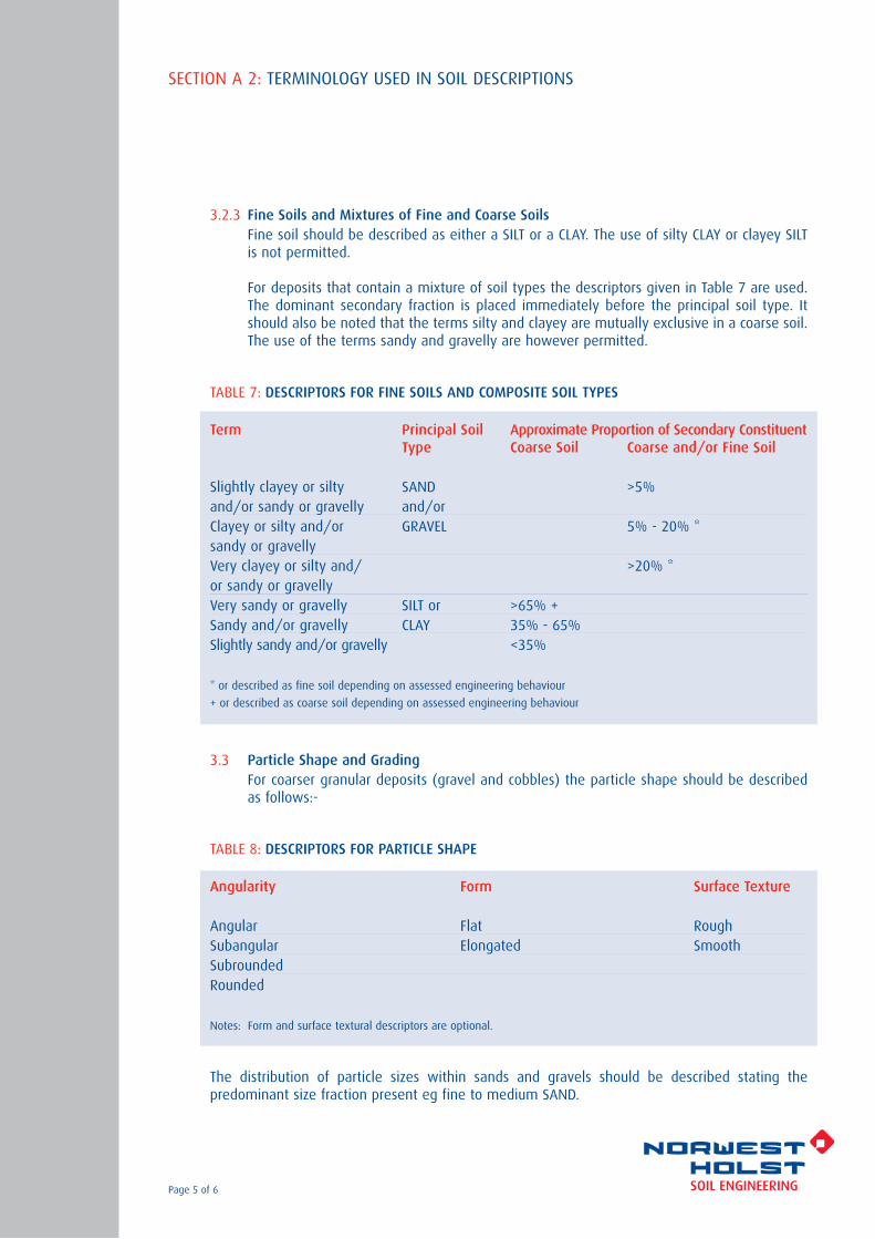
3.2.3 Fine Soils and Mixtures of Fine and Coarse SoilsFine soil should be described as either a SILT or a CLAY. The use of silty CLAY or clayey SILTis not permitted.
For deposits that contain a mixture of soil types the descriptors given in Table 7 are used.The dominant secondary fraction is placed immediately before the principal soil type. Itshould also be noted that the terms silty and clayey are mutually exclusive in a coarse soil.The use of the terms sandy and gravelly are however permitted.
TABLE 7: DESCRIPTORS FOR FINE SOILS AND COMPOSITE SOIL TYPES
Term Principal Soil Approximate Proportion of Secondary ConstituentType Coarse Soil Coarse and/or Fine Soil
Slightly clayey or silty SAND >5%and/or sandy or gravelly and/orClayey or silty and/or GRAVEL 5% - 20% *sandy or gravellyVery clayey or silty and/ >20% *or sandy or gravellyVery sandy or gravelly SILT or >65% +Sandy and/or gravelly CLAY 35% - 65%Slightly sandy and/or gravelly <35%
* or described as fine soil depending on assessed engineering behaviour
+ or described as coarse soil depending on assessed engineering behaviour
3.3 Particle Shape and GradingFor coarser granular deposits (gravel and cobbles) the particle shape should be describedas follows:-
TABLE 8: DESCRIPTORS FOR PARTICLE SHAPE
Angularity Form Surface Texture
Angular Flat RoughSubangular Elongated SmoothSubroundedRounded
Notes: Form and surface textural descriptors are optional.
The distribution of particle sizes within sands and gravels should be described stating thepredominant size fraction present eg fine to medium SAND.
SECTION A 2: TERMINOLOGY USED IN SOIL DESCRIPTIONS
Page 5 of 6

FIGURE 1: PARTICLE ANGULARITY AND FORM TERMS
References
01) BS 5930: (1999) Code of Practice for Site Investigation. British Standards Institution.
02) NHSED, Manual on the Sampling and Logging of Soil and Rock (SALOSAR), 2005, 3rd Ed.
03) BS 1377: 1990 Methods of Test for Soils for Civil Engineering Purposes. Part 9 BritishStandards Institution.
SECTION A 2: TERMINOLOGY USED IN SOIL DESCRIPTIONS
Page 6 of 6

SUPPORTING FACTUAL DATA
SECTION ANotes on Fieldwork, Logging andLaboratory Testing
MADE GROUND DESCRIPTIONTERMINOLOGY

SECTION A 3: TERMINOLOGY USED IN THE DESCRIPTION OF MADE GROUND
Page 1 of 4
1.0 GENERAL DEFINITIONS
Man made soils may be defined as those materials that have not been laid down bygeomorphological processes. Under the heading of ‘man made soils’ two distinct material typescan be identified as follows:-
TABLE 1: DEFINITIONS FOR MAN MADE SOILS
NATURAL SOILS Use normal BS5930 approach and terminology as outlined previously.(Reworked) Usually not too much of a problem. Can be tested in accordance with
BS1377.
MAN MADE Can frequently also be described using normal approach and terminologyMATERIALS as above, and tested geotechnically.
Includes materials that defy description in any standard manner and includes a range of exotic materials and artefacts. Often not testable in the field or in the laboratory. For example cannot measure strength of abicycle frame or liquid limit of plastic.
There is also a distinction between the terms "Fill" and "Made Ground" as follows:
FILL = Material placed under engineering controlMADE GROUND = Material placed without any kind of control, ie non engineered
2.0 IDENTIFICATION OF MAN MADE SOILS
Some common examples of man made soils are given in Table 2 on the following page. The tableillustrates that the heading of ‘man made’ soils can cover a wide variety of materials, some ofwhich may not readily appear to be anything other than natural.
Natural soils re-laid by man may be difficult to identify as such but look for evidence in the formof artefacts or relic structure in the material.
For example as few as one or two artefacts may be diagnostic (rare brick fragments or car bodyat base of trial pit). Lenses or pockets of clay that are laminated etc help to indicate naturalmaterial that has been relaid. However be aware of the following:
* Contamination by driller (Clinker from around rig, green grass from 15m…).
* Contamination during trial pitting (brick rubble can fall from the upper layers in a pit and then get pushed in to natural deposits by the action of the excavator bucket).

TABLE 2: EXAMPLES OF COMMONLY FOUND MAN MADE SOIL
CATEGORY EXAMPLE
Natural Soils re-laid by man Embankment FillColliery Spoil (Coarse Discard)Drainage Layer e.g Gravel
Man Made Materials that can be Abutment backfill e.g Crushed rockdescribed and which are testable Colliery Spoil (Fine Discard)geotechnically Mine Tailings from non-coal mines
Crushed ConcretePulverised Fuel Ash (PFA)Chalk whiting (slurry from cement manufacture)
Man Made Materials that are NOT readily Landfilldescribable and which are not testable Demolition rubble (including frames, slates etc)geotechnically Fly tipped materials
Burgy (glass work waste)
3.0 DESCRIPTION OF MAN MADE SOILSInformation that needs to be reported includes the following:-
* Origin of materials, if known from desk study.
* Layers and their inclination to inform on mode of tipping, whether ponded, end tipped, spreadof stockpiled.
* Large objects, obstructions such as concrete, masonry walls, old cars.
* Presence of hollow objects, compressible/collapsible objects or voids such as oil drums, cellars,tanks.
* Chemical wastes and dangerous or hazardous substances such as creosote, hospital wastes,unlabelled drums, asbestos.
* Decomposable materials with note on degree of decomposition such as garden waste, paper.
* Smell such as organic, phenolic, sulphurous, petrol.
* Striking colours
* Any dating possible such as on bottle types, newspapers, papers.
* Signs of heat or combustion such as steam, smoke, burnt shale.
NOTES
* In general do not attempt to assign strength or in situ density descriptors to made ground.Where describing fill as opposed to made ground it may be possible to use the descriptors thatare used for natural soils.
SECTION A 3: TERMINOLOGY USED IN THE DESCRIPTION OF MADE GROUND
Page 2 of 4

* Large or hollow objects cannot be sampled so the description is the sole information oncondition and character of the features.
* Group together under the above categories, give volumetric percentages where possible.
Granular made ground may be given a particle size, although the following descriptionmethodology should be employed.
MADE GROUND: Grey fine to coarse gravel sized fragments of brick and concrete.
OR
MADE GROUND: Grey gravely clay with occasional subangular cobble sized fragments of brick.Gravel sized fragments are angular to subangular, fine, medium and coarse of brick.
In these two examples, note the use of term ‘sized fragments’ to describe the granular content.Because the material is man made we do not use the terms sand, gravel or cobbles etc in thesame context as for natural soils. In other words it would be incorrect to use the following:
MADE GROUND: Grey gravelly clay with occasional cobbles. Gravel is angular coarse of brick,cobbles are rounded of brick.
The use of sand, gravel or cobble prior to ‘sized fragments’ is only intended to define a size rangeto the granular made ground material.
Similar grain size indicators can also be used to describe the size of other man made materialssuch as concrete, bituminous road surfacing etc. In addition the terms can also be used to describenatural material that has been modified by man, such as wood that may be present in the formof railway sleepers etc. Where whole man made items are identified they should be described asfollows:
‘with numerous wooden railway sleepers’
For such materials it is necessary to add size measurements, since no other quantifying terms areused.
4.0 DEFINITIONS OF SOME MAN MADE SOILS
There is generally a lack of national guidance on the meaning of common terms used in madeground. This applies particularly to man made materials. For this reason it is vital to provide asmuch information as possible on the material being logged, whilst staying within the guidanceprovided in these notes.
For some sites it is advisable to determine a set of definitions for the likely range of made groundto be encountered at the start of the project. This will allow all those responsible for thedescription of materials to provide unified logs for the site.
SECTION A 3: TERMINOLOGY USED IN THE DESCRIPTION OF MADE GROUND
Page 3 of 4

Some suggestions for one group of commonly encountered made ground are given below.
COMBUSTION PRODUCTS, often physically unstable and usually containing concentrations of metalsand poly aromatic hydrocarbons. The definitions below are workable compromises.
ASH: Sand or silt size by definition, so do not need but can use "ash sand", and cannothave "gravel size ash" although cinders can be gravel size but readily crush down. Can include unburnt coal.
CLINKER: Gravel size or larger by definition so do not need but can use "clinker gravel", and cannot have "sand size clinker".
SLAG: Materials fused or poured as liquid or scum or froth, of any size or shape, and will beat least strong. If in blocks or layers, can present difficulties for borehole or trial pit penetration. Slag is often pelletised, expanded or crushed for reuse in construction.
References
01) BS 5930 (1999) Code of Practice for Site Investigation. British Standards Institution.
02) NHSED, Manual on the Sampling and Logging of Soil and Rock, (SALOSAR) 2005, 3rd Ed.
SECTION A 3: TERMINOLOGY USED IN THE DESCRIPTION OF MADE GROUND
Page 4 of 4

SUPPORTING FACTUAL DATA
SECTION ANotes on Fieldwork, Logging andLaboratory Testing
AGGRESSIVE GROUND ANDGROUNDWATER CONDITIONS
SECTION A 6: ASSESSMENT OF AGGRESSIVE GROUND AND GROUNDWATER CONDITIONS
Page 1 of 4
Certain ground and groundwater conditions may be described as aggressive depending on their chemicalcomposition which is related to previous industrial use. Where foundations are proposed to beconstructed on industrial sites or on landfill sites in which the ground or groundwater may becontaminated with chemical waste, detailed consideration needs to be given to both the method ofinvestigation and the severity of ground and groundwater conditions with respect to constructionmaterials. For such sites it will usually be necessary to undertake a full chemical analysis in order toidentify the potentially aggressive compounds.
On sites where new concrete foundations are to be constructed in natural ground it is usually onlynecessary to examine the sulfate content and pH level of the ground. The sulfate content of soils varieswidely and can range from being virtually absent to extremely high concentrations in crystals such asgypsum. In between these two extremes sulfate may be disseminated throughout a soil or may bepresent in discrete bands or lenses. Because of this wide variation in the sulfate content of soils, themost reliable indication of possible aggressive conditions can be obtained by testing representativesamples of groundwater. In order to take account of natural variations in the distribution of sulfates inthe ground, samples should be taken at a number of locations that are well spaced across the site andat different depths.
The methods for the determination of total sulfate of soil and the sulfate content of groundwater and2:1 aqueous soil extracts are given in various specifications including BS 1377: 1990: Part 3: Section 5(ref 01). The results of tests performed in accordance with BS 1377 yield results which are expressed aspercentage of dry weight retained or grammes/litre SO3. Tests performed in accordance with otherspecifications however, tend to express results as SO4.
The classification of natural sulfate conditions is based on BRE Special Digest 1 (2005) (ref 02). This digestmakes most use of sulfate values expressed as milligrammes/litre SO4. In order to convert the resultsexpressed as SO3 (BS 1377) to SO4 (BRE Digest ) it is necessary to apply a multiplication factor of 1.2.In the following discussion of sulfate conditions values given in the tables are expressed in terms of SO4.
The current approach to the classification of aggressive ground conditions is based on the aggressivechemical environment for concrete or ACEC. This takes into account the type of site, sulfate concentrationand ground water acidity and mobility. Different site assessment procedures are used for natural ground,for brownfield sites that contain industrial waste and pyritic ground. The reactions of sulfates in thepresence of other ions, notably carbonate and magnesium are also taken into account.
As with the previous Special Digest 1, there are five design sulfate classes (designated DS1 to DS5) forthe site, although in the current digest natural ground and brownfield sites are now covered by separatetables. More subdivision of ACEC Class is given in the table for brownfield locations and this reflects thecomplexity of conditions that often apply.
In general when the results of sulfate determinations are assessed emphasis must be given to thesamples which fall in the higher classes. Therefore if eight out of ten samples are found to be nonaggressive and fall within Class DS1 and the remainder fall within Class DS2 it will be necessary to adoptthe precautions appropriate to Class DS2 conditions for the whole site. The current digest differentiatesbetween ‘natural ground locations’ and brownfield locations’.
Table 1 on page 2 is reproduced from the digest and deals with natural ground locations.

TABLE 1: AGGRESSIVE CHEMICAL ENVIRONMENT FOR CONCRETE (ACEC) CLASSIFICATION FOR NATURAL GROUND LOCATIONS (a)
SULFATE GROUNDWATERDESIGN SULFATE 2:1 WATER/SOIL GROUNDWATER TOTAL STATIC MOBILE ACECCLASS FOR EXTRACT (b) POTENTIAL WATER WATER CLASS FOR LOCATION SULFATE (c) LOCATION
1 2 3 4 5 6 7(SO4 mg/l) (SO4 mg/l) (SO4 %) (pH) (pH)
DS-1 <500 <400 <0.24 >2.5 AC-1s>5.5 (d) AC-1 (d)
2.5-5.5 AC-2z
DS-2 500-1500 400-1400 0.24-0.6 >3.5 AC-1s>5.5 AC-2
2.5-3.5 AC-2s2.5-5.5 AC-3z
DS-3 1600-3000 1500-3000 0.7-1.2 >3.5 AC-2s>5.5 AC-3
2.5-3.5 AC-3s2.5-5.5 AC-4
DS-4 3100-6000 3100-6000 1.3-2.4 >3.5 AC-3s>5.5 AC-4
2.5-3.5 AC-4s2.5-5.5 AC-5
DS-5 >6000 >6000 >2.4 >3.5 AC-4s2.5-3.5 >2.5 AC-5
NOTESa) Applies to locations on sites that comprise either undisturbed ground that is in its natural state or clean fill derived from such ground.
b) The limits of Design Sulfate Classes based on 2:1 water/soil extracts have been lowered relative to previous digests.c) Applies only to locations where concrete will be exposed to sulphate ions (SO4) which may result from the oxidation of sulfides(eg pyrite) following ground disturbance.d) For flowing water that is potentially aggressive to concrete owing to high purity or an aggressive carbon dioxide level greater than15mg/l, increase the ACEC Class to AC-2z.
Explanation of suffix symbols to ACEC ClassSuffix ‘s’ indicates that the water has been classified as staticConcrete place in a ACEC Classes that include the suffix ‘z’ primarily have to resist acid conditions and may be made with any of the cementslisted in Table D2 in the Digest.
Additional testing is required for those natural sites that contain pryrite. In particular it is essential to takeaccount of the total potential sulfate content which might result from oxidation following grounddisturbance. On such sites it is necessary to determine total sulfate content (AS% S04), total sulfur (TS%).The total potential sulfate is then determined from TPS%SO4=3.0 x TS%S. Finally the amount ofoxidisable sulfides (OS as %SO4) is determined by subtracting the acid soluble sulfates(AS%S04) fromthe total potential sulfate content: OS%SO4 = TPS%SO4 – AS%S04. It is important to note that this testingis in addition to and not instead of the standard sulfate determination testing.
Unless the site can be demonstrated to comprise natural ground, Table 2 for brownfield locations mustbe used in all assessments for the design of concrete. It should be noted that the effects of themagnesium ion become relevant to concrete design for certain Design Sulfate Classes.
SECTION A 6: ASSESSMENT OF AGGRESSIVE GROUND AND GROUNDWATER CONDITIONS
Page 2 of 4

SECTION A 6: ASSESSMENT OF AGGRESSIVE GROUND AND GROUNDWATER CONDITIONS
Page 3 of 4
TABLE 2: AGGRESSIVE CHEMICAL ENVIRONMENT FOR CONCRETE (ACEC) CLASSIFICATION FOR BROWNFIELD LOCATIONS (a)
SULFATE AND MAGNESIUM GROUNDWATERDESIGN SULFATE 2:1 WATER/SOIL GROUNDWATER TOTAL STATIC MOBILE ACECCLASS FOR EXTRACT (b) POTENTIAL WATER WATER CLASS FOR LOCATION SULFATE (c) LOCATION
1 2 3 4 5 6 7 8 9(SO4 mg/l) (Mg mg/l) (SO4 mg/l) (Mg mg/l) (SO4 %) (pH) (d) (pH) (d)
DS-1 <500 - <400 - <0.24 >2.5 AC-1s>6.5 (d) AC-15.5-6.5 AC-2z4.5-5.5 AC-3z2.5-4.5 AC-4z
DS-2 500-1500 - 400-1400 - 0.24-0.6 >5.5 AC-1s>6.5 AC-2
2.5-3.5 AC-2s5.5-6.5 AC-3z4.5-5.5 AC-4z2.5-4.5 AC-5z
DS-3 1600-3000 - 1500-3000 - 0.7-1.2 >5.5 AC-2s>6.5 AC-3
2.5-5.5 AC-3s5.5-6.5 AC-42.5-5.5 AC-5
DS-4 3100-6000 <1200 3100-6000 <1000 1.3-2.4 >5.5 AC-3s>6.5 AC-4
2.5-3.5 AC-4s2.5-6.5 AC-5
DS-4m 3100-6000 >1200 (e) 3100-6000 >1000 (e) 1.3-2.4 >5.5 AC-3s>6.5 AC-4m
2.5-5.5 AC-4ms2.5-6.5 AC-5m
DS-5 >6000 <1200 >6000 <1000 >2.4 >5.5 AC-4s2.5-3.5 >2.5 AC-5
DS-5m >6000 >1200 (e) >6000 >1000 (e) >2.4 >5.5 AC-4ms2.5-5.5 >2.5 AC-5m
NOTESa) Brownfield locations are those sites or parts of sites that might contain chemical residues produced by industrial processes.
b) The limits of Design Sulfate Classes based on 2:1 water/soil extracts have been lowered relative to previous digests.c) Applies only to locations where concrete will be exposed to sulfate ions (SO4) which may result from the oxidation of sulfides(eg pyrite) following ground disturbance.d) An additional account is taken of hydrochloric and nitric acids by adjustment to sulfate contente) The limit on water soluble magnesium does not apply to brackish groundwater (chloride content between 12000mg/l and17000mg/l). This allows ‘m’ to be omitted from the relevant ACEC classification. Sea water (chloride about 18000mg/l) and strongerbrines are not covered by this table.
Explanation of suffix symbols to ACEC ClassSuffix ‘s’ indicates that the water has been classified as staticConcrete placed in ACEC Classes that include the suffix ‘z’ primarily have to resist acid conditions and may be made with any of the cements listed in Table D2 in the Digest.Suffix ‘m’ relates to the higher levels of magnesium in Design Sulfate Classes 4 and 5.

SECTION A 6: ASSESSMENT OF AGGRESSIVE GROUND AND GROUNDWATER CONDITIONS
Page 4 of 4
The pH value of groundwater provides a crude measure of the potential aggressiveness due to thepresence of organic acids. The standard procedure for measuring the acidity of soils and groundwater isthe electrometric method using a pH meter and is described in BS 1377 (1990): Part 3: Section 5. ThepH value of pure water is 7.0 and the presence of acid substances will yield results with values less than7. It should be noted however that the pH of most natural waters depends mainly on the dissolvedcarbon dioxide content and therefore lies between pH values of 6.5 and 8.5. It is generally accepted thatsoils or groundwater with pH values in the range 6 to 9 may be classified as near neutral. It should benoted that the pH value of soil and groundwater can change with time and it is therefore necessary tocarry out testing on fresh samples of soil or water.
The pH value of the soil or groundwater also needs to be taken into consideration when the recordedsulfate content is borderline between two classes or approaches the upper limit of a given class. In thesecircumstances both the pH value and the mobility of the groundwater needs to be assessed and wheredoubt exists, the sample should be placed in the more severe class of the sulfate classification. Thisgeneral approach may be justified on the grounds that the acids present will tend to break down theconcrete surface and therefore make it more susceptible to sulfate attack. This will be especially so if thesample contains large amounts of sulfides since these can be converted to sulfuric acid.
Organic acids are often found in peaty or marshy soils in which the pH value is below 6.0. In such soilsit will be necessary to take specific precautions to protect any concrete which would be exposed toorganic acids. The recommended precautionary measures outlined in Tomlinson (2001) (ref 03) could befollowed. In all cases where mineral acids are present the groundwater is likely to be aggressive withregard to foundation concrete and in these circumstances the recommendations given in BRE SpecialDigest Part C will need to be followed.
Apart form acid groundwater, the effects of static and mobile ground water tables are taken into accountin the digest in ‘Box C9’ and the incremental rules in this table need to be viewed in relation to TablesC1 and C2 in the Digest.
Alkaline groundwater is not generally considered aggressive to concrete unless present in highconcentrations. Unless the aggregate used in foundation concrete is of a reactive type, pH values ofgroundwater up to pH = 14 need not be considered as problematic.
References
01) BS 1377: 1990 Methods of Test for Soils for Civil Engineering Purposes. Part 3: Chemical and Electrochemical Tests, British Standards Institution.
02) Building Research Establishment: 2005: Concrete in Aggressive Ground. BRE Special Digest 1. Building Research Station, Garston
03) Tomlinson M.J: 2001: Foundation Design and Construction. 7th Edition, Pearson, Prentice Hall.

SUPPORTING FACTUAL DATA
SECTION BExploratory Hole Records andField Data
EXPLORATORY HOLE LEGEND AND NOTATION SHEET

EXPORATORY HOLE LOG LEGENDS
Page 1 of 2
CODE DESCRIPTION LEGEND
101 Topsoil
CODE DESCRIPTION LEGEND
806 Coal
104 Concrete
102 Made Ground 807 Breccia
201 Clay
808 Conglomerate
301 Silt
809 Fine Grained Igneous
401 Sand
810 Medium Grained Igneous
501 Gravel
811 Coarse Grained Igneous
601 Peat
812 Fine Grained Metamorphic
701 Cobbles
813 Coarse / Medium Grained Metamorphic
730 Boulders
EVT Evaporite
801 Mudstone
MWS Mine Workings
802 Siltstone
904 Grout
803 Sandstone
905 Arising
804 Limestone
BLK Zone of No Recovery
805 Chalk
WTR Water
Note: Most soils types comprise a mixture of particle sizes. These soiltypes are represented graphically on the exploratory hole logs bycombining the legends shown on this sheet.
NOTATION USED ON EXPORATORY HOLE LOGS
Page 2 of 2
SAMPLING NOTATION
U Undisturbed U100 or U38 sample(not differentiated)
P Piston Sample
BLK Block Sample
M Mazier Sample
TW Thin Walled Sample
L Liner Sample obtained from windowless sampler
D Small Disturbed Sample
B Bulk Disturbed Sample
LB Large Bulk Disturbed Sample
C Core Sample
ES Environmental Soil Sample
EW Environmental Water Sample
W Water Sample
UF No Recovery in U Sample
PF No Recovery in P Sample
TWF No Recovery in TW Sample
IN SITU TEST NOTATION
S Standard Penetration Test
C Cone Penetration Test
NP No Penetration for S or C
V Vane Test
HV Hand Vane
HP Hand Penetrometer
K Permeability Test(test type not differentiated)
Pr Pressuremeter Test
OTHER NOTATION
TCR Total Core Recovery
SCR Solid Core Recovery
RQD Rock Quality Designation
FI Fracture Index
If Fracture Spacing
NI Non Intact
NA Data Not Applicable
NR Data Not Recorded
SUPPORTING FACTUAL DATA
SECTION BExploratory Hole Records andField Data
CABLE PERCUSSION ANDROTARY DRILLING RECORDS

CSSSSSSSSSSSSSSSSSSSSSS
50/160mm (3,4,13,31,6/10mm)50/180mm (4,9,16,22,12/30mm)N=39 (3,8,9,12,10,8)N=24 (2,3,3,7,7,7)N=24 (3,3,5,5,6,8)N=25 (3,3,4,7,7,7)N=31 (3,4,6,8,8,9)N=33 (4,4,7,8,9,9)N=37 (4,5,7,9,10,11)N=38 (4,6,7,10,10,11)N=40 (5,6,8,10,11,11)N=42 (5,7,10,10,10,12)N=44 (6,8,10,10,11,13)N=45 (6,8,10,11,12,12)N=48 (6,8,10,12,13,13)N=50 (7,8,11,12,13,14)50/285mm (6,9,13,14,14,9/60mm)50/255mm (7,10,13,14,16,7/30mm)55/255mm (6,10,14,15,16,10/30mm)50/230mm (7,10,14,15,18,3/5mm)50/255mm (7,8,11,14,15,10/30mm)50/235mm (8,10,12,14,18,6/10mm)62/245mm (9,11,14,14,20,14/20mm)50/125mm (5,20,23,27/50mm)57/160mm (10,15,22,25,10/10mm)
5.907.509.009.709.709.709.709.709.709.709.709.709.709.709.709.709.709.709.709.709.709.709.709.709.70
DRYDRYDRYDRYDRYDRYDRYDRYDRYDRYDRYDRYDRYDRYDRYDRYDRYDRYDRYDRYDRYDRYDRYDRYDRY
Contract No.Project
Client
Consultant
Method
Drilling Rig
Coordinates
Ground LevelOrientationDate StartedDate Completed
Hole ID.Norwest Holst Soil Engineering Ltd.BOREHOLE LOG CABLE PERCUSSION
DrillerLogged by
Form
Version
Revised 15/08/2007
3.04
ARIAL CP HEADER
PROGRESS BORING DETAILS
CASING WATER STRIKES
GENERAL NOTES SPT DETAILS
RemarksDate Time Holedepth depth
Casing Waterdepth
Hard Stratafrom depth
Hard Stratato depth
Chisellinghours
Holediam.
Max depth ofhole at dia.
Casingdiameter
Max depth ofcasing of dia.
Date Time Strike atdepth depth
Rise to Time takento rise
Flow Casing depthat strike time
Casing depthto seal flow
Depth Type Incremental blow count/penetration
Header
NOTES: All depths in metres, all diameters in millimetres,water strike rise time in minutes, chiselling time in hours.
* Seating blows only.
Remarks
CasingWaterDepthAll measurements during drilling taken fom street level.1.
2. Concrete at road level (0.5m) and car park basement floorslab (2.8m) drilled out by McGee's.3. Groundwater encountered at 51.0m, fast inflow rate.4. 50mm standpipe installed to base of River TerraceDeposits (9.70m) with a 3.0m slotted section at base ofpipe.5. Flush cover installed in concrete at basement level carpark.6. Backfill details: grout to 9.7m, gravel to 6.8m,bentonite seal to 3.8m, concrete to basement level at 3.3m.
F15001NM Rothschild Bank
Stanhope plc
Arup Geotechnics
Cable Percussion
Dando 2000MHIM
5832703.82 E180999.52 N
25/08/200726/08/2007
14.39m ODVertical
BH01
200
25/08/200725/08/200726/08/200726/08/200727/08/2007
52.30
08001700080017000800
200
5.5028.9528.9552.3052.00
9.70
0.009.709.709.700.00
DRYDRYDRYDRY32.00
26/08/2007 51.00 44.00 20 Fast 9.70 NR
Start of BoringEnd of ShiftStart of ShiftEnd of BoringInstallation
5.907.509.00
10.5012.5014.5016.5018.5020.5022.5024.5026.5028.5030.5032.5034.5036.5038.5040.5042.5044.5046.5048.9051.4052.30
CC

SPT N & Installation
NOTES: All depths in metres, all diameters in millimetres.See header sheet for details of boring, progress and waterstrikes. See legend sheet for key to symbols.
Hole ID.Norwest Holst Soil Engineering Ltd.BOREHOLE LOG CABLE PERCUSSION
DrillerLogged by
Form
Version
Revised 29/03/2006
3.08
ARIAL CP LOG
Contract No.Project
Client
Consultant
Method
Drilling Rig
Coordinates
Ground LevelOrientationDate StartedDate Completed
Description of Strata LegendG.L.
BelowDepth
LevelDatum
Sampling& depth
SPT type(U blows)
F15001NM Rothschild Bank
Stanhope plc
Arup Geotechnics
Cable Percussion
Dando 2000MHIM
180999.52 N5832703.82 E
Vertical25/08/200726/08/2007
14.39m OD
BH01
0.50
3.30
5.50
9.55
9.80
13.89
11.09
8.89
4.84
4.59
B1
B2
B3
B4
D5U6
5.50 5.90
5.90 6.35
7.50 7.95
9.00 9.45
9.559.60 10.00
C50/160mm
C50/180mm
C39
(30)
C
C
C
5.90
7.50
9.00
6.21
7.83
9.45
MADE GROUND: Concrete (road level)
VOID: Basement car park.
MADE GROUND: Basement floor slab.
Very dense brown, white, grey and black very sandyangular to subrounded fine to coarse flint GRAVEL.Sand is fine to coarse.(RIVER TERRACE DEPOSITS)
From 9.0m: Sand becoming predominantly coarse.
Stiff brownish grey slightly sandy CLAY with
Sheet 1 of 6

SPT N & Installation
NOTES: All depths in metres, all diameters in millimetres.See header sheet for details of boring, progress and waterstrikes. See legend sheet for key to symbols.
Hole ID.Norwest Holst Soil Engineering Ltd.BOREHOLE LOG CABLE PERCUSSION
DrillerLogged by
Form
Version
Revised 29/03/2006
3.08
ARIAL CP LOG
Contract No.Project
Client
Consultant
Method
Drilling Rig
Coordinates
Ground LevelOrientationDate StartedDate Completed
Description of Strata LegendG.L.
BelowDepth
LevelDatum
Sampling& depth
SPT type(U blows)
F15001NM Rothschild Bank
Stanhope plc
Arup Geotechnics
Cable Percussion
Dando 2000MHIM
180999.52 N5832703.82 E
Vertical25/08/200726/08/2007
14.39m OD
BH01
10.50
19.95
3.89
5.56
D7
D8
U9
D10
D11
U12
D13
D14
U15
D16
D17
U18
D19
D20
U21
D22
10.00
10.50 10.96
11.50 11.95
11.95
12.50 12.95
13.50 13.95
13.95
14.50 14.95
15.50 15.95
15.95
16.50 16.95
17.50 17.95
17.95
18.50 18.95
19.50 19.95
19.95
S24
(30)
S24
(35)
S25
(35)
S31
(40)
S33
(45)
S
S
S
S
S
10.50
12.50
14.50
16.50
18.50
10.95
12.95
14.95
16.95
18.95
____________9.55m 9.80m : occasional subrounded medium flintgravel and rare fine black silty sandy pockets.(LONDON CLAY FORMATION)____________9.80m 10.50m : Firm grey slightly sandy CLAY withrare subrounded fine siliceous gravel. (LONDON CLAYFORMATION)
Firm greyish brown CLAY.(LONDON CLAY FORMATION)
At 12.50m: With localised fine sandy pockets.
At 13.95m: With localised pockets of finegreyish black sand (0.02 x 0.01m)
From 15.95m: Becoming sandy.
At 16.50m: With fine gravel size white selenitecrystals.
From 17.95m: Becoming less sandy.
Sheet 2 of 6

SPT N & Installation
NOTES: All depths in metres, all diameters in millimetres.See header sheet for details of boring, progress and waterstrikes. See legend sheet for key to symbols.
Hole ID.Norwest Holst Soil Engineering Ltd.BOREHOLE LOG CABLE PERCUSSION
DrillerLogged by
Form
Version
Revised 29/03/2006
3.08
ARIAL CP LOG
Contract No.Project
Client
Consultant
Method
Drilling Rig
Coordinates
Ground LevelOrientationDate StartedDate Completed
Description of Strata LegendG.L.
BelowDepth
LevelDatum
Sampling& depth
SPT type(U blows)
F15001NM Rothschild Bank
Stanhope plc
Arup Geotechnics
Cable Percussion
Dando 2000MHIM
180999.52 N5832703.82 E
Vertical25/08/200726/08/2007
14.39m OD
BH01
28.80 14.41
D23
U24
D25
D26
U27
D28
D29
U30
D31
D32
U33
D34D35
D36
U37
D38
20.50 20.95
21.50 21.85
21.85
22.50 22.95
23.50 23.95
23.95
24.50 24.95
25.50 25.95
25.95
26.50 26.95
27.50 27.95
27.9528.00
28.50 28.95
29.50 29.85
29.85
S37
(50)
S38
(55)
S40
(65)
S42
(70)
S44
(70)
S
S
S
S
S
20.50
22.50
24.50
26.50
28.50
20.95
22.95
24.95
26.95
28.95
Stiff grey CLAY. (LONDON CLAY FORMATION)
From 20.50m: Becoming slightly sandy with finegravel size white selenite crystals.
From 22.50m: Becoming increasingly sandy withrare fine gravel size selenite crystals.
From 24.50m: Becoming very stiff.
From 25.95m: With occasional pockets of finesand (0.1 x 0.2m) and sand partings.
From 26.50m: Becoming less sandy.
From 27.85m: With increasing partings of finesand. At 28.00m: Grey claystone recovered as angularto subangular fine to coarse sand and gravel sizefragments.
Very stiff grey very sandy CLAY with white angularfine to coarse gravel size selenite crystals.(LONDON CLAY FORMATION)
Sheet 3 of 6

SPT N & Installation
NOTES: All depths in metres, all diameters in millimetres.See header sheet for details of boring, progress and waterstrikes. See legend sheet for key to symbols.
Hole ID.Norwest Holst Soil Engineering Ltd.BOREHOLE LOG CABLE PERCUSSION
DrillerLogged by
Form
Version
Revised 29/03/2006
3.08
ARIAL CP LOG
Contract No.Project
Client
Consultant
Method
Drilling Rig
Coordinates
Ground LevelOrientationDate StartedDate Completed
Description of Strata LegendG.L.
BelowDepth
LevelDatum
Sampling& depth
SPT type(U blows)
F15001NM Rothschild Bank
Stanhope plc
Arup Geotechnics
Cable Percussion
Dando 2000MHIM
180999.52 N5832703.82 E
Vertical25/08/200726/08/2007
14.39m OD
BH01
34.50
38.50
20.11
24.11
D39
U40
D41
D42
U43
D44
D45
U46
D47
D48
U49
D50
D51
U52
D53
30.50 30.95
31.50 31.90
31.90
32.50 32.95
33.50 33.95
33.95
34.50 34.95
35.50 35.90
35.90
36.50 36.92
37.50 37.80
37.80
38.50 38.91
39.50 39.90
39.90
S45
(75)
S48
(80)
S50
(85)
S50/285mm
(85)
S50/255mm
(95)
S
S
S
S
S
30.50
32.50
34.50
36.50
38.50
30.95
32.95
34.95
36.94
38.91
Remaining Detail : 29.85m 29.85m : From29.85m: Becoming slightly sandy.
From 30.50m: Selenite crystals becoming finegravel size.
From 31.90m: With greyish brown pockets of finesand (0.1 x 0.05m)
Very stiff grey CLAY with white fine gravel sizeselenite crystals.(LONDON CLAY FORMATION)
From 35.90m: With partings of fine brown sand.
From 36.50m: With occasional angular coarsegravel of claystone.
Very stiff grey CLAY.(LONDON CLAY FORMATION)
Sheet 4 of 6

SPT N & Installation
NOTES: All depths in metres, all diameters in millimetres.See header sheet for details of boring, progress and waterstrikes. See legend sheet for key to symbols.
Hole ID.Norwest Holst Soil Engineering Ltd.BOREHOLE LOG CABLE PERCUSSION
DrillerLogged by
Form
Version
Revised 29/03/2006
3.08
ARIAL CP LOG
Contract No.Project
Client
Consultant
Method
Drilling Rig
Coordinates
Ground LevelOrientationDate StartedDate Completed
Description of Strata LegendG.L.
BelowDepth
LevelDatum
Sampling& depth
SPT type(U blows)
F15001NM Rothschild Bank
Stanhope plc
Arup Geotechnics
Cable Percussion
Dando 2000MHIM
180999.52 N5832703.82 E
Vertical25/08/200726/08/2007
14.39m OD
BH01
40.50
41.85
45.85
26.11
27.46
31.46
D54
U55
D56
D57
U58
D59
D60
U61
D62
D63
U64
D65
D66
40.50 40.90
41.50 41.85
41.85
42.50 42.85
43.50 43.95
43.95
44.50 44.90
45.50 45.85
45.85
46.50 46.88
47.50 47.90
47.90
48.90 49.50
S55/255mm
(100)
S50/230mm
(110)
S50/255mm
(110)
S50/235mm
(120)
S62/245mm
S
S
S
S
S
40.50
42.50
44.50
46.50
48.90
40.91
42.88
44.91
46.89
49.30
Remaining Detail : 39.90m 39.90m : From39.90m: With partings of light grey fine sand.
Very stiff grey CLAY with abundant pockets of finesand and sand partings and frequent white finegravel size selenite crystals.(LONDON CLAY FORMATION)
Very stiff grey sandy CLAY.(LONDON CLAY FORMATION)
From 42.50m: Becoming increasingly sandy.
At 45.5m: Becoming hard.
Very stiff grey CLAY with pockets of fine sand (0.1x 0.05m) and sandy partings.(LONDON CLAY FORMATION)
From 46.50m: Becoming less sandy.
From 47.90m: Becoming increasingly sandy.
Sheet 5 of 6

SPT N & Installation
NOTES: All depths in metres, all diameters in millimetres.See header sheet for details of boring, progress and waterstrikes. See legend sheet for key to symbols.
Hole ID.Norwest Holst Soil Engineering Ltd.BOREHOLE LOG CABLE PERCUSSION
DrillerLogged by
Form
Version
Revised 29/03/2006
3.08
ARIAL CP LOG
Contract No.Project
Client
Consultant
Method
Drilling Rig
Coordinates
Ground LevelOrientationDate StartedDate Completed
Description of Strata LegendG.L.
BelowDepth
LevelDatum
Sampling& depth
SPT type(U blows)
F15001NM Rothschild Bank
Stanhope plc
Arup Geotechnics
Cable Percussion
Dando 2000MHIM
180999.52 N5832703.82 E
Vertical25/08/200726/08/2007
14.39m OD
BH01
50.50
51.00
51.70
52.30
36.11
36.61
37.31
37.91
D67
U68
D69
UF
D70
50.50
50.70 51.05
51.40
52.00
52.30
(100)
S50/125mm
S57/160mm
S
S
51.40
52.30
51.68
52.61
Very stiff grey CLAY with pockets of fine sand (0.1x 0.05m) and sandy partings.(LONDON CLAY FORMATION)
Very stiff grey, greenish grey, brown, blueishgreen, friable sandy CLAY.(LAMBETH GROUP)
Very dense greyish brown fine SAND.(LAMBETH GROUP SAND CHANNEL)
Very stiff brownish grey, blue, green very sandyCLAY.(LAMBETH GROUP)
Cable Percussion boring complete at 52.30 m.
Sheet 6 of 6

SUPPORTING FACTUAL DATA
SECTION BExploratory Hole Records andField Data
INSPECTION PIT / TRIAL PIT / TRIAL TRENCH RECORDS

Consultant
Method
Equipment
Coordinates
Ground LevelDate StartedDate Completed
Description of Strata LegendG.L.
BelowDepth
LevelDatum
Sampling
NOTES: All depths in metres, all soil strengths in kPa.See legend sheet for key to symbols and abbreviations.
Hole ID.Norwest Holst Soil Engineering Ltd.TRIAL PIT LOG
Remarks
A
B
C
D
Bearing
Sketch Plan of Trial PitStability
Shoring
Groundwater
Remarks
Logged by
All bearings given relate to magnetic North
Form
Version
Revised
ARIAL TP LOG
3.05
15/02/2006
Contract No.Project
Client
Good
Trial pit located in basement, in old archive office.1.2. All depth measurements relative to basement floor level.3. Trial pit excavated by McGees.4. 2 x Environmental Samples taken at 2.0m (A & B) consistsof 1x plastic tub, 1x vial and 1 x 250ml glass jar.
Standing at 1.5m
F15001
Arup Geotechnics
NM Rothschild Bank
Stanhope plcBreaker
Hand Excavated
IM
1.15m
15/10/200715/10/2007
1.54m
TP03
1.66
2.03 ES1ES2
2.002.00
CONCRETE: Reinforced concrete with 30mm and 15mmrebar.
At 0.92m: Rebar.
SAND and GRAVEL (RIVER TERRACE DEPOSITS)
Trial pit complete at 2.03 m.
Sheet 1 of 1

Ground Level
Form No. SI IPSFSA4 Revision No.
TP03
Hole ID
Fig no.
Date Date Date
REMARKS - All dimensions in meters unless stated
1.01 Issue Date 20/11/2006
Project Name Trial Pit Sketch Plan & Section(Sheet 1 of 1)
Project No.
Engineer
NMR BANK
F15001
Arup Geotechnics
Client
Plotted by Hannah Sydney
Coordinates
Stanhope PLC
Checked by Approved by
PLAN:
SECTION
Reinforced ConcreteReinforced Concrete
Terrace GravelsTerrace Gravels
1.66m
0.37m
GL
Corner of Wall
Wall
1.54m
1.15m

SUPPORTING FACTUAL DATA
SECTION BExploratory Hole Records andField Data
GROUNDWATER / GAS MONITORING/ SAMPLING RESULTS

NOTES:
Form No. Revision No.
Comments/Observations
London Clay
Type of Stratum
F15001
Arup Geotechnics
Stanhope Plc
Depth of Inflow
(m)
51.00 Fast
(m)
44.00
Engineer
Client 01
Table no.
BH01
Level After 20mins
Rate of Inflow
3.01SI EHGWI Issue Date
Project Name NM Rothschild Bank Groundwater Inflows Recorded In
Exploratory Holes
07/02/2006
Project No.
Exploratory Hole ID

Depths are recorded as metres below Lower Ground Floor Slab Surface
Recorded by: Checked by: Approved by:
Date: Date: Date:Form No. Revision No. 2.02 Issue Date
Project Name NM ROTHSCHILD BANK Groundwater Readings For Installations
10/07/2006
Project No.
Engineer
Client
COMMENTS
For multiple installations, record piezometer 1 as PZ1, piezometer 2 as PZ2 etc.For piezometers installation depth = tip depth. For standpipes = base of pipe
NOTES:
02
SI GWR
F15001
ARUP GEOTECHNICS
STANHOPE PLC
PZ=Piezometer, SP=Standpipe
Fig no.
Installation Type
Installation Depth
(m)Exploratory Hole ID
SP 6.00BH01 4.77
Date07/09/2007
4.77
Date31/08/2007
4.79
Date15/11/2007
4.69
Date18/10/2007
4.83
Date17/09/2007
Recorded Water Level (m)
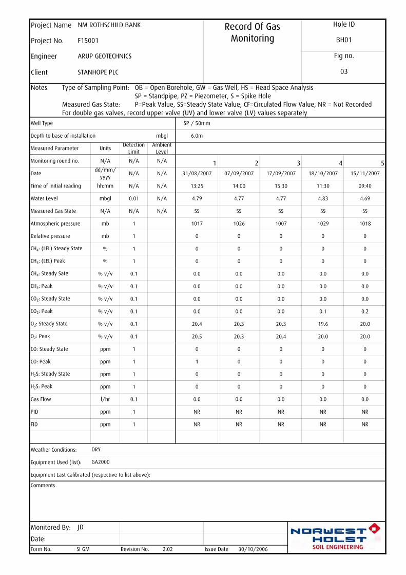
Notes Type of Sampling Point:
Measured Gas State:For double gas valves, record upper valve (UV) and lower valve (LV) values separately
Weather Conditions:
Equipment Used (list):
Equipment Last Calibrated (respective to list above):
Comments
Monitored By:
Form No. Revision No.
NRNR NR NR NR
NR NR NR NR
0 0
0.0 0.0 0.1
4.79 4.77 4.77 4.83
0
0 0 0 0 0
0 0 0 0
20.0
20.5 20.3 20.4 20.0 20.0
20.4 20.3 20.3 19.6
0.2
0.0 0.0 0.0 0.0
0.0
0.0 0.0 0.0 0.0
0
0.0 0.0 0.0
1029
0
0 0 0 0 0
0 0 0
SS
1018
0 0 0 0 0
1017 1026 1007
SS SS SS SS
mb 1Relative pressure
N/A 1 2 3
PID
FID
CO: Peak
H2S: Steady State
H2S: Peak
Gas Flow
Ambient Level
31/08/2007 07/09/2007
O2: Steady State
Atmospheric pressure
CH4: (LEL) Steady State
CH4: (LEL) Peak
CH4: Steady Sate
Water Level
CH4: Peak
18/10/2007 15/11/2007
4 5
14:00 15:30
6.0m
SP / 50mm
0
0
0 0 0 0
1 0
mbglDepth to base of installation
hh:mm
%
N/A
N/A
Measured Parameter
Date
ARUP GEOTECHNICS
STANHOPE PLC
N/A
% 1
dd/mm/ yyyy
13:25
N/A
UnitsDetection
Limit
SI GM
ppm 1
JD
GA2000
Hole ID
BH01
03
Fig no.
Project Name NM ROTHSCHILD BANK Record Of Gas Monitoring
30/10/2006
Project No.
0.01
Engineer
Client
F15001
ppm
OB = Open Borehole, GW = Gas Well, HS = Head Space AnalysisSP = Standpipe, PZ = Piezometer, S = Spike HoleP=Peak Value, SS=Steady State Value, CF=Circulated Flow Value, NR = Not Recorded
11:30 09:40
1
17/09/2007
0.0
Issue Date
N/A
DRY
2.02
1
0.0
4.69
NR
0.0
0.0
0.0
0.0
0.0 0.0 0.0
CO: Steady State
mb
% v/v
% v/v
% v/v
% v/v
ppm
% v/v
CO2: Steady State
CO2: Peak
Well Type
Monitoring round no.
mbgl
N/A
N/A N/A
0.1
0.1
1
Time of initial reading
l/hr
ppm
ppm
Measured Gas State
ppm
O2: Peak
% v/v
N/A
1
N/A
1
0.1
0.1
1
1
0.1
0.1
0.1
Date:

SUPPORTING FACTUAL DATA
SECTION CLaboratory Testing
KEY TO LABORATORY TESTRESULTS

KEY TO LABORATORY SUMMARY SHEETS
Page 1 of 2
COMMON TO ALL SUMMARIES
Sample Type U Undisturbed sample AMAL Amalgamated sampleP Piston sample B Bulk disturbed sampleTW Thin walled sample BLK Block sampleL Liner sample C Rock coreD Small disturbed sample
Test status Any result in italics indicates a test that is not within the scope of the UKAS accreditation for this laboratory.
SUMMARY OF LABORATORY SOIL TESTS: INDEX / CLASSIFICATION TESTS
Particle density p Small pyknometer method g Gas jar method
Plastic index N/P Non plastic, although liquid limit will have been determined if requested
Particle size (PSD) 1 Following value in silt column denotes combined clay and silt fractionp Folowing value in clay column denotes sedimentation by pipette, else
sedimentation is by hydrometer.
SUMMARY OF LABORATORY SOIL TESTS: STRENGTH AND PERMEABILITY TESTS
Triaxial UU Single stage unconsolidated quick undrainedUUM Multi stage unconsolidated quick undrainedUU3 Set of 3 unconsolidated quick undrainedCU Single stage consolidated undrainedCUM Multi stage consolidated undrainedCU3 Set of 3 consolidated undrainedCD Single stage consolidated drainedCDM Multi stage consolidated drainedCD3 Set of 3 consolidated drainedNote that single stage tests are reported assuming phi = 0 for total stress and c' = 0 for effective stress
Consol Oed One-dimensional oedometer Hyd Hydraulic cell consolidationmv Coefficient of compressibility quoted for p0 to p0 + 100kPa, where determined
Permeability C Constant head permeability T Triaxial permeability
Shearbox SSB Small shear box LSB Large shear boxP Peak value r Residual valueRS Ring shear

KEY TO LABORATORY SUMMARY SHEETS
Page 2 of 2
SUMMARY OF LABORATORY SOIL RE-USE TEST
MCV s MCV value at natural or specified moisture contentint Intercept of calibration line in MCV calibration
SUMMARY OF LABORATORY ROCK STRENGTH TESTS
Point Load Type D Diametral A Axial(Combination of) I Irregular lump B Block
L Test performed parallel to planes of weaknessP Test performed perpendicular to planes of weaknessX Invalid failure of point load (not broken between points of load application)
SUMMARY OF LABORATORY ROCK MATERIALS TESTS
Ten% fines w Soaked test d Dry test
POINT LOAD INDEX RESULT
Point Load Type D Diametral A Axial(Combination of) I Irregular lump B Block
L Test performed parallel to planes of weaknessP Test performed perpendicular to planes of weaknessX Invalid failure of point load (not broken between points of load application)
Dimensions W Diameter of core or average smallest width perpendicular to axis of loading in a block or irregular lump
D Distance between platens when just in contact with specimenD' Distance between platens at point of failureDe Equivalent core diameter Is P/De2
Is(50) F x Is F (De/50)0.45
Is(50) point load strength index corrected for a diametral test of core diameter 50mmFor Axial/Lump tests De2 = (4/Pi) x (W x D')For Diametral tests De2 = D x D'
Important note: summary sheets are provided for convenience and in no way replace individual test result sheets which shall,without exception, be regarded as the definitive result.
SUPPORTING FACTUAL DATA
SECTION CLaboratory Testing
LABORATORY SOIL TEST SUMMARY SHEETS

% % % % % % % % % %
002 B 01 0¹ 39 61 0
004 B 01 1¹ 32 67 0
005 D 01 28 70 25 45 88
007 D 01 61 36 3 0 0
010 D 01 28 76 24 52 100
016 D 01 26 72 23 49 100
019 D 01 61 38 1 0 0
025 D 01 49 35 2 14 0
028 D 01 21 80 29 51 100
031 D 01 49 46 5 0 0
035 D 01 6¹ 2 92 0
038 D 01 22 62 24 38 100
044 D 01 25 68 28 40 100
047 D 01 62 37 1 0 0
050 D 01 24 74 25 49 100
056 D 01 23 71 27 44 100
059 D 01 41 28 30 0 0
062 D 01 25 72 25 47 100
065 D 01 39 32 29 0 0
067 D 01 14 38 15 23 100
Approved by:
Print date
Revision No. 2.01 Issue Date 17/07/2006
Leeds Laboratory
Stuart Kirk 03/10/2007
BH01 50.50 50.50
BH01 45.85 45.85
BH01 47.90 47.90
BH01 41.85 41.85
BH01 43.95 43.95
BH01 35.90 35.90
BH01 37.80 37.80
BH01 29.85 29.85
BH01 33.95 33.95
BH01 25.95 25.95
BH01 28.00 28.00
BH01 21.85 21.85
BH01 23.95 23.95
BH01 15.95 15.95
BH01 17.95 17.95
BH01 10.00 10.00
BH01 11.95 11.95
BH01 9.00 9.00
BH01 9.55 9.55
Sam
ple n
o.
Bulk D
ensity
Specim
en d
epth
m
Sam
ple typ
e
Moistu
re Conte
nt
Mg/m³
Dry
Density
Par
ticle D
ensity
Plastic Lim
it
Pas
sing 4
25µm
Clay
Silt
Gra
vel
Particle size
Sand
Cobbles
Hole ID
BH01
Sam
ple d
epth
m
5.90
Liquid Lim
it
2.90
Project Name NM Rothschild Bank Classification Tests Classification Tests Classification Tests Classification Tests SummarySummarySummarySummary
Engineer Arup Geotechnics
Client Stanhope plc
Project No. F15001
Plastic Index
Linear
Shrinka
ge
Specim
en n
o.

% % % % % % % % % %Sam
ple n
o.
Bulk D
ensity
Specim
en d
epth
m
Sam
ple typ
e
Moistu
re Conte
nt
Mg/m³
Dry
Density
Par
ticle D
ensity
Plastic Lim
it
Pas
sing 4
25µm
Clay
Silt
Gra
vel
Particle size
Sand
Cobbles
Hole ID
Sam
ple d
epth
m
Liquid Lim
it
Project Name NM Rothschild Bank Classification Tests Classification Tests Classification Tests Classification Tests SummarySummarySummarySummary
Engineer Arup Geotechnics
Client Stanhope plc
Project No. F15001
Plastic Index
Linear
Shrinka
ge
Specim
en n
o.
070 D 01 36 50 15 0 0
End
Approved by:
Print date
Revision No.
BH01 52.30 52.30
Leeds Laboratory
03/10/2007
2.01 Issue Date 17/07/2006
Stuart Kirk

c Ø c Ø
% Mg/m³ kPa º m²/MN m/s kPa º
006 U 1 29 1.98 UU 121 0
009 U 1 29 3.65 UU 88 0
012 U 1 27 2.00 UU 101 0
015 U 1 27 2.04 UU 109 0
018 U 1 28 2.01 UU 132 0
021 U 1 28 1.93 UU 127 0
024 U 1 28 2.00 UU 91 0
027 U 1 29 1.98 UU 123 0
030 U 1 28 1.99 UU 142 0
033 U 1 23 2.11 UU 266 0
037 U 1 23 2.10 UU 249 0
040 U 1 20 2.03 UU 282 0
043 U 1 26 2.03 UU 221 0
046 U 1 26 2.00 UU 155 0
049 U 1 27 1.95 UU 256 0
052 U 1 25 2.00 UU 169 0
055 U 1 25 1.97 UU 183 0
058 U 1 25 1.96 UU 243 0
061 U 1 24 1.97 UU 341 0
End
Approved by:
Stuart Kirk
Revision No. 2.01
BH01 43.50 43.55
BH01 45.50 45.61
BH01 39.50 39.63
BH01 41.50 41.62
BH01 35.50 35.57
BH01 37.50 37.70
BH01 31.50 31.58
BH01 33.50 33.55
BH01 27.50 27.52
BH01 29.50 29.65
BH01 23.50 23.53
BH01 25.50 25.55
BH01 19.50 19.55
BH01 21.50 21.61
BH01 15.50 15.55
BH01 17.50 17.51
BH01 11.50 11.50
BH01 13.50 13.52
Leeds Laboratory
08/08/2006Issue Date
03/10/2007Print date
9.70
Triaxial
Type
Specimen no.
Bulk Density
Moisture Content
Sample no.
Specimen depth m
Sample type
Shearbox
Type
Consol
Type mv
Type
Permeability
Client Stanhope plc
Project No. F15001
Project Name NM Rothschild Bank Strength and Strength and Strength and Strength and Permeability SummaryPermeability SummaryPermeability SummaryPermeability Summary
Engineer Arup Geotechnics
Hole ID
BH01
Sample depth m
9.60
K


SUPPORTING FACTUAL DATA
SECTION CLaboratory Testing
LABORATORY SOIL TESTDATA SHEETS

Description
Estimated percentage retained on 425µm sieve:Preparation of sample: NaturalRemarks:
Moisture content of soil passing 425µm
Approved by:
Print date
Revision No.
1
19/06/2007
03/10/2007
005Sample Type
DSpecimen Depth
Liquid And Plastic Limit Liquid And Plastic Limit Liquid And Plastic Limit Liquid And Plastic Limit TestTestTestTest
Hole IDBH01
Liquidity index:
Liquid limit:Plastic limit:Plasticity index:
70%25%
Sushil Sharda
12%
Leeds Laboratory
0.16
2.02 Issue Date
Client Stanhope plc
4532%
Natural moisture content: 28%
Brown slightly gravelly CLAY.
Test Method: BS1377: Part 2: 1990: Clause 4.3 and 5
Engineer Arup Geotechnics
Project Name NM Rothschild Bank
Project No. F15001
Specimen Number
Sample Depth9.55m
Sample Number
9.55m
13
15
17
19
21
23
25
27
60 64 68 72 76 80
Moisture Content - %
Cone Penetration - m
m
CL
ML MI MH
CI CH
MV
CV CE
ME0
20
40
60
80
100
0 10 20 30 40 50 60 70 80 90 100
Liquid Limit (%)
Plasticity Index(%)

Description
Estimated percentage retained on 425µm sieve:Preparation of sample: NaturalRemarks:
Moisture content of soil passing 425µm
Approved by:
Print date
Revision No.
1
19/06/2007
03/10/2007
010Sample Type
DSpecimen Depth
Liquid And Plastic Limit Liquid And Plastic Limit Liquid And Plastic Limit Liquid And Plastic Limit TestTestTestTest
Hole IDBH01
Liquidity index:
Liquid limit:Plastic limit:Plasticity index:
76%24%
Sushil Sharda
0%
Leeds Laboratory
0.08
2.02 Issue Date
Client Stanhope plc
5228%
Natural moisture content: 28%
Brown CLAY.
Test Method: BS1377: Part 2: 1990: Clause 4.3 and 5
Engineer Arup Geotechnics
Project Name NM Rothschild Bank
Project No. F15001
Specimen Number
Sample Depth11.95m
Sample Number
11.95m
13
15
17
19
21
23
25
27
70 74 78 82 86 90
Moisture Content - %
Cone Penetration - m
m
CL
ML MI MH
CI CH
MV
CV CE
ME0
20
40
60
80
100
0 10 20 30 40 50 60 70 80 90 100
Liquid Limit (%)
Plasticity Index(%)

Description
Estimated percentage retained on 425µm sieve:Preparation of sample: NaturalRemarks:
Moisture content of soil passing 425µm
Approved by:
Print date
Revision No.
1
19/06/2007
03/10/2007
016Sample Type
DSpecimen Depth
Liquid And Plastic Limit Liquid And Plastic Limit Liquid And Plastic Limit Liquid And Plastic Limit TestTestTestTest
Hole IDBH01
Liquidity index:
Liquid limit:Plastic limit:Plasticity index:
72%23%
Sushil Sharda
0%
Leeds Laboratory
0.06
2.02 Issue Date
Client Stanhope plc
4926%
Natural moisture content: 26%
Brown CLAY.
Test Method: BS1377: Part 2: 1990: Clause 4.3 and 5
Engineer Arup Geotechnics
Project Name NM Rothschild Bank
Project No. F15001
Specimen Number
Sample Depth15.95m
Sample Number
15.95m
13
15
17
19
21
23
25
27
60 64 68 72 76 80
Moisture Content - %
Cone Penetration - m
m
CL
ML MI MH
CI CH
MV
CV CE
ME0
20
40
60
80
100
0 10 20 30 40 50 60 70 80 90 100
Liquid Limit (%)
Plasticity Index(%)
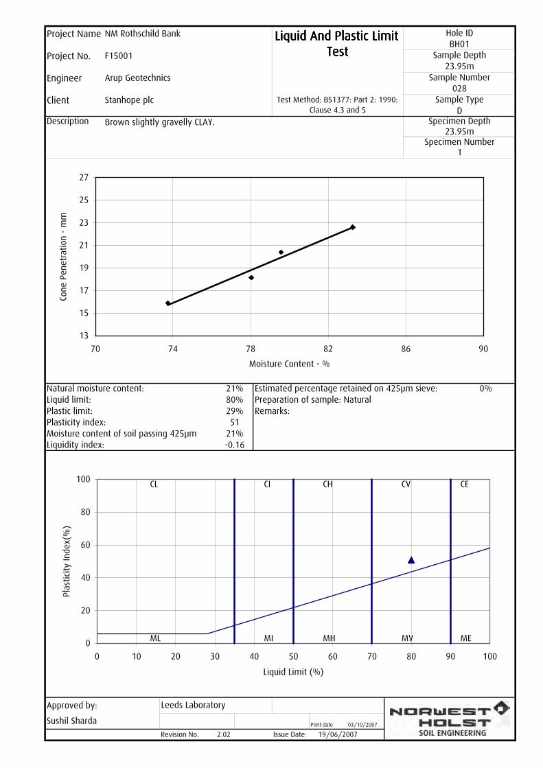
Description
Estimated percentage retained on 425µm sieve:Preparation of sample: NaturalRemarks:
Moisture content of soil passing 425µm
Approved by:
Print date
Revision No.
1
19/06/2007
03/10/2007
028Sample Type
DSpecimen Depth
Liquid And Plastic Limit Liquid And Plastic Limit Liquid And Plastic Limit Liquid And Plastic Limit TestTestTestTest
Hole IDBH01
Liquidity index:
Liquid limit:Plastic limit:Plasticity index:
80%29%
Sushil Sharda
0%
Leeds Laboratory
-0.16
2.02 Issue Date
Client Stanhope plc
5121%
Natural moisture content: 21%
Brown slightly gravelly CLAY.
Test Method: BS1377: Part 2: 1990: Clause 4.3 and 5
Engineer Arup Geotechnics
Project Name NM Rothschild Bank
Project No. F15001
Specimen Number
Sample Depth23.95m
Sample Number
23.95m
13
15
17
19
21
23
25
27
70 74 78 82 86 90
Moisture Content - %
Cone Penetration - m
m
CL
ML MI MH
CI CH
MV
CV CE
ME0
20
40
60
80
100
0 10 20 30 40 50 60 70 80 90 100
Liquid Limit (%)
Plasticity Index(%)

Description
Estimated percentage retained on 425µm sieve:Preparation of sample: NaturalRemarks:
Moisture content of soil passing 425µm
Approved by:
Print date
Revision No.
1
19/06/2007
03/10/2007
038Sample Type
DSpecimen Depth
Liquid And Plastic Limit Liquid And Plastic Limit Liquid And Plastic Limit Liquid And Plastic Limit TestTestTestTest
Hole IDBH01
Liquidity index:
Liquid limit:Plastic limit:Plasticity index:
62%24%
Sushil Sharda
0%
Leeds Laboratory
-0.05
2.02 Issue Date
Client Stanhope plc
3822%
Natural moisture content: 22%
Brown CLAY.
Test Method: BS1377: Part 2: 1990: Clause 4.3 and 5
Engineer Arup Geotechnics
Project Name NM Rothschild Bank
Project No. F15001
Specimen Number
Sample Depth29.85m
Sample Number
29.85m
13
15
17
19
21
23
25
27
50 54 58 62 66 70
Moisture Content - %
Cone Penetration - m
m
CL
ML MI MH
CI CH
MV
CV CE
ME0
20
40
60
80
100
0 10 20 30 40 50 60 70 80 90 100
Liquid Limit (%)
Plasticity Index(%)

Description
Estimated percentage retained on 425µm sieve:Preparation of sample: NaturalRemarks:
Moisture content of soil passing 425µm
Approved by:
Print date
Revision No.
1
19/06/2007
03/10/2007
044Sample Type
DSpecimen Depth
Liquid And Plastic Limit Liquid And Plastic Limit Liquid And Plastic Limit Liquid And Plastic Limit TestTestTestTest
Hole IDBH01
Liquidity index:
Liquid limit:Plastic limit:Plasticity index:
68%28%
Sushil Sharda
0%
Leeds Laboratory
-0.08
2.02 Issue Date
Client Stanhope plc
4025%
Natural moisture content: 25%
Brown CLAY.
Test Method: BS1377: Part 2: 1990: Clause 4.3 and 5
Engineer Arup Geotechnics
Project Name NM Rothschild Bank
Project No. F15001
Specimen Number
Sample Depth33.95m
Sample Number
33.95m
13
15
17
19
21
23
25
27
60 64 68 72 76 80
Moisture Content - %
Cone Penetration - m
m
CL
ML MI MH
CI CH
MV
CV CE
ME0
20
40
60
80
100
0 10 20 30 40 50 60 70 80 90 100
Liquid Limit (%)
Plasticity Index(%)
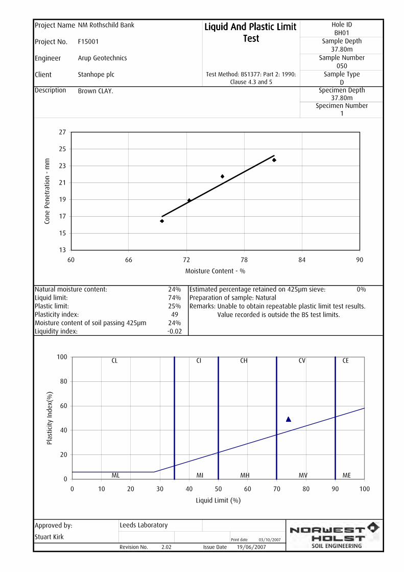
Description
Estimated percentage retained on 425µm sieve:Preparation of sample: NaturalRemarks:
Moisture content of soil passing 425µm
Approved by:
Print date
Revision No.
1
19/06/2007
03/10/2007
050Sample Type
DSpecimen Depth
Liquid And Plastic Limit Liquid And Plastic Limit Liquid And Plastic Limit Liquid And Plastic Limit TestTestTestTest
Hole IDBH01
Liquidity index:
Liquid limit:Plastic limit:Plasticity index:
74%25%
Stuart Kirk
0%
Leeds Laboratory
-0.02
2.02 Issue Date
Client Stanhope plc
4924%
Natural moisture content: 24%
Brown CLAY.
Unable to obtain repeatable plastic limit test results. Value recorded is outside the BS test limits.
Test Method: BS1377: Part 2: 1990: Clause 4.3 and 5
Engineer Arup Geotechnics
Project Name NM Rothschild Bank
Project No. F15001
Specimen Number
Sample Depth37.80m
Sample Number
37.80m
13
15
17
19
21
23
25
27
60 66 72 78 84 90
Moisture Content - %
Cone Penetration - m
m
CL
ML MI MH
CI CH
MV
CV CE
ME0
20
40
60
80
100
0 10 20 30 40 50 60 70 80 90 100
Liquid Limit (%)
Plasticity Index(%)

Description
Estimated percentage retained on 425µm sieve:Preparation of sample: NaturalRemarks:
Moisture content of soil passing 425µm
Approved by:
Print date
Revision No.
1
19/06/2007
03/10/2007
056Sample Type
DSpecimen Depth
Liquid And Plastic Limit Liquid And Plastic Limit Liquid And Plastic Limit Liquid And Plastic Limit TestTestTestTest
Hole IDBH01
Liquidity index:
Liquid limit:Plastic limit:Plasticity index:
71%27%
Sushil Sharda
0%
Leeds Laboratory
-0.09
2.02 Issue Date
Client Stanhope plc
4423%
Natural moisture content: 23%
Brown CLAY.
Test Method: BS1377: Part 2: 1990: Clause 4.3 and 5
Engineer Arup Geotechnics
Project Name NM Rothschild Bank
Project No. F15001
Specimen Number
Sample Depth41.85m
Sample Number
41.85m
13
15
17
19
21
23
25
27
60 64 68 72 76 80
Moisture Content - %
Cone Penetration - m
m
CL
ML MI MH
CI CH
MV
CV CE
ME0
20
40
60
80
100
0 10 20 30 40 50 60 70 80 90 100
Liquid Limit (%)
Plasticity Index(%)

Description
Estimated percentage retained on 425µm sieve:Preparation of sample: NaturalRemarks:
Moisture content of soil passing 425µm
Approved by:
Print date
Revision No.
1
19/06/2007
03/10/2007
062Sample Type
DSpecimen Depth
Liquid And Plastic Limit Liquid And Plastic Limit Liquid And Plastic Limit Liquid And Plastic Limit TestTestTestTest
Hole IDBH01
Liquidity index:
Liquid limit:Plastic limit:Plasticity index:
72%25%
Sushil Sharda
0%
Leeds Laboratory
0.00
2.02 Issue Date
Client Stanhope plc
4725%
Natural moisture content: 25%
Brown CLAY.
Test Method: BS1377: Part 2: 1990: Clause 4.3 and 5
Engineer Arup Geotechnics
Project Name NM Rothschild Bank
Project No. F15001
Specimen Number
Sample Depth45.85m
Sample Number
45.85m
13
15
17
19
21
23
25
27
60 64 68 72 76 80
Moisture Content - %
Cone Penetration - m
m
CL
ML MI MH
CI CH
MV
CV CE
ME0
20
40
60
80
100
0 10 20 30 40 50 60 70 80 90 100
Liquid Limit (%)
Plasticity Index(%)
Description
Estimated percentage retained on 425µm sieve:Preparation of sample: NaturalRemarks:
Moisture content of soil passing 425µm
Approved by:
Print date
Revision No.
1
19/06/2007
03/10/2007
067Sample Type
DSpecimen Depth
Liquid And Plastic Limit Liquid And Plastic Limit Liquid And Plastic Limit Liquid And Plastic Limit TestTestTestTest
Hole IDBH01
Liquidity index:
Liquid limit:Plastic limit:Plasticity index:
38%15%
Sushil Sharda
0%
Leeds Laboratory
-0.04
2.02 Issue Date
Client Stanhope plc
2314%
Natural moisture content: 14%
Light grey sandy CLAY.
Test Method: BS1377: Part 2: 1990: Clause 4.3 and 5
Engineer Arup Geotechnics
Project Name NM Rothschild Bank
Project No. F15001
Specimen Number
Sample Depth50.50m
Sample Number
50.50m
13
15
17
19
21
23
25
27
30 32 34 36 38 40
Moisture Content - %
Cone Penetration - m
m
CL
ML MI MH
CI CH
MV
CV CE
ME0
20
40
60
80
100
0 10 20 30 40 50 60 70 80 90 100
Liquid Limit (%)
Plasticity Index(%)
Description
PARTICLE SIZE
Silt and clay:Sand:Gravel:Cobbles:
Approved by:
Print date
Revision No. 3.01 Issue Date 28/04/2006
002
62
WET SIEVE DATACumulative % passing
72
Sieve size mm
Cumulative % passing
39
Leeds Laboratory
Sushil Sharda 03/10/2007
48
0
1
46
100
100
100
93
100 29
18
893
82 4
28.0
20.0
Sieve size mm
50.0
37.5
125.0
100.0
75.0
63.0
43100
14.0
10.0
6.3
5.0
3.35
Project Name NM Rothschild Bank
Client Stanhope plc
Particle Size Particle Size Particle Size Particle Size DistributionDistributionDistributionDistribution
Hole IDBH01
Project No. F15001 Sample Depth5.90m
Engineer Arup Geotechnics Sample Number
2.90mSpecimen No.
1
Brown sandy GRAVEL.
BS 1377: Part 2: 1990: 9.2Sample type
BSpecimen Depth
0.212
0.150
0.063
39
36
0.300
0.425
2.00
1.18
0.600
General remarks
610
%
0
0.002
0.006
0.03
0.06
0.2
0.6
2 6 20
60
200
0
10
20
30
40
50
60
70
80
90
100
Sieve Size (mm)
Percentage Passing (%)
CLAYSILT SAND GRAVEL
COBBLESFine Medium Coarse Fine Medium Coarse Fine Medium Coarse

Description
PARTICLE SIZE
Silt and clay:Sand:Gravel:Cobbles:
Approved by:
Print date
Revision No. 3.01 Issue Date 28/04/2006
004
60
WET SIEVE DATACumulative % passing
73
Sieve size mm
Cumulative % passing
32
Leeds Laboratory
Sushil Sharda 03/10/2007
42
1
2
40
100
100
100
100
100 21
14
896
84 4
28.0
20.0
Sieve size mm
50.0
37.5
125.0
100.0
75.0
63.0
37100
14.0
10.0
6.3
5.0
3.35
Project Name NM Rothschild Bank
Client Stanhope plc
Particle Size Particle Size Particle Size Particle Size DistributionDistributionDistributionDistribution
Hole IDBH01
Project No. F15001 Sample Depth9.00m
Engineer Arup Geotechnics Sample Number
9.00mSpecimen No.
1
Brown sandy GRAVEL.
BS 1377: Part 2: 1990: 9.2Sample type
BSpecimen Depth
0.212
0.150
0.063
33
29
0.300
0.425
2.00
1.18
0.600
General remarks
670
%
1
0.002
0.006
0.03
0.06
0.2
0.6
2 6 20
60
200
0
10
20
30
40
50
60
70
80
90
100
Sieve Size (mm)
Percentage Passing (%)
CLAYSILT SAND GRAVEL
COBBLESFine Medium Coarse Fine Medium Coarse Fine Medium Coarse

Description
PARTICLE SIZEClay:Silt:Sand:Gravel:Cobbles:
Particle density: Assumed
Approved by:
Print date
Revision No. 3.01 Issue Date 28/04/2006
007
100 940.0413
Cumulative% passing
WET SIEVE DATA SEDIMENTATION DATACumulative % passing
100
0.0025
0.0071
Sieve size mm
Cumulative % passing
3
Leeds Laboratory
Sushil Sharda 03/10/2007
570.0013
0.0037 68
76
63
100
97
87
83
0.0214
0.0154
99
100
100
100
100
100
100 100
100
100100
100 99
28.0
20.0
Sieve size mm
50.0
37.5
125.0
100.0
75.0
63.0
100100
14.0
10.0
6.3
5.0
Equivalent particle diametermm
3.35
Project Name NM Rothschild Bank
Client Stanhope plc
Particle Size Particle Size Particle Size Particle Size DistributionDistributionDistributionDistribution
Hole IDBH01
Project No. F15001 Sample Depth10.00m
Engineer Arup Geotechnics Sample Number
10.00mSpecimen No.
1
Brown CLAY.
BS 1377: Part 2: 1990: 9.2, 9.5Sample type
DSpecimen Depth
0.212
0.150
0.063
100
100
0.300
0.425
2.00
1.18
0.600
2.65Mg/m³
General remarks
00
%6136
0.002
0.006
0.03
0.06
0.2
0.6
2 6 20
60
200
0
10
20
30
40
50
60
70
80
90
100
Sieve Size (mm)
Percentage Passing (%)
CLAYSILT SAND GRAVEL
COBBLESFine Medium Coarse Fine Medium Coarse Fine Medium Coarse

Description
PARTICLE SIZEClay:Silt:Sand:Gravel:Cobbles:
Particle density: Assumed
Approved by:
Print date
Revision No. 3.01 Issue Date 28/04/2006
019
100 960.0405
Cumulative% passing
WET SIEVE DATA SEDIMENTATION DATACumulative % passing
100
0.0024
0.0070
Sieve size mm
Cumulative % passing
1
Leeds Laboratory
Sushil Sharda 03/10/2007
560.0013
0.0036 67
76
64
100
99
88
84
0.0210
0.0151
100
100
100
100
100
100
100 100
100
100100
100 100
28.0
20.0
Sieve size mm
50.0
37.5
125.0
100.0
75.0
63.0
100100
14.0
10.0
6.3
5.0
Equivalent particle diametermm
3.35
Project Name NM Rothschild Bank
Client Stanhope plc
Particle Size Particle Size Particle Size Particle Size DistributionDistributionDistributionDistribution
Hole IDBH01
Project No. F15001 Sample Depth17.95m
Engineer Arup Geotechnics Sample Number
17.95mSpecimen No.
1
Brown CLAY.
BS 1377: Part 2: 1990: 9.2, 9.5Sample type
DSpecimen Depth
0.212
0.150
0.063
100
100
0.300
0.425
2.00
1.18
0.600
2.65Mg/m³
General remarks
00
%6138
0.002
0.006
0.03
0.06
0.2
0.6
2 6 20
60
200
0
10
20
30
40
50
60
70
80
90
100
Sieve Size (mm)
Percentage Passing (%)
CLAYSILT SAND GRAVEL
COBBLESFine Medium Coarse Fine Medium Coarse Fine Medium Coarse
Description
PARTICLE SIZEClay:Silt:Sand:Gravel:Cobbles:
Particle density: Assumed
Approved by:
Print date
Revision No. 3.01 Issue Date 28/04/2006
025
92 810.0402
Cumulative% passing
WET SIEVE DATA SEDIMENTATION DATACumulative % passing
92
0.0024
0.0070
Sieve size mm
Cumulative % passing
2
Leeds Laboratory
Stuart Kirk 03/10/2007
450.0013
0.0036 58
65
52
87
85
77
75
0.0206
0.0148
85
87
100
100
100
100
100 85
85
85100
92 85
28.0
20.0
Sieve size mm
50.0
37.5
125.0
100.0
75.0
63.0
86100
14.0
10.0
6.3
5.0
Equivalent particle diametermm
3.35
Project Name NM Rothschild Bank
Client Stanhope plc
Particle Size Particle Size Particle Size Particle Size DistributionDistributionDistributionDistribution
Hole IDBH01
Project No. F15001 Sample Depth21.85m
Engineer Arup Geotechnics Sample Number
21.85mSpecimen No.
1
Brown slightly gravelly CLAY.
BS 1377: Part 2: 1990: 9.2, 9.5Sample type
DSpecimen Depth
0.212
0.150
0.063
86
86
0.300
0.425
2.00
1.18
0.600
2.65Mg/m³
General remarks
140
%4935
0.002
0.006
0.03
0.06
0.2
0.6
2 6 20
60
200
0
10
20
30
40
50
60
70
80
90
100
Sieve Size (mm)
Percentage Passing (%)
CLAYSILT SAND GRAVEL
COBBLESFine Medium Coarse Fine Medium Coarse Fine Medium Coarse
Description
PARTICLE SIZEClay:Silt:Sand:Gravel:Cobbles:
Particle density: Assumed
Approved by:
Print date
Revision No. 3.01 Issue Date 28/04/2006
031
100 890.0439
Cumulative% passing
WET SIEVE DATA SEDIMENTATION DATACumulative % passing
100
0.0030
0.0087
Sieve size mm
Cumulative % passing
5
Leeds Laboratory
Stuart Kirk 03/10/2007
470.0014
0.0055 58
64
51
100
96
79
75
0.0228
0.0163
99
100
100
100
100
100
100 100
100
100100
100 99
28.0
20.0
Sieve size mm
50.0
37.5
125.0
100.0
75.0
63.0
100100
14.0
10.0
6.3
5.0
Equivalent particle diametermm
3.35
Project Name NM Rothschild Bank
Client Stanhope plc
Particle Size Particle Size Particle Size Particle Size DistributionDistributionDistributionDistribution
Hole IDBH01
Project No. F15001 Sample Depth25.95m
Engineer Arup Geotechnics Sample Number
25.95mSpecimen No.
1
Brown CLAY.
BS 1377: Part 2: 1990: 9.2, 9.5Sample type
DSpecimen Depth
0.212
0.150
0.063
100
100
0.300
0.425
2.00
1.18
0.600
2.65Mg/m³
General remarks
00
%4946
0.002
0.006
0.03
0.06
0.2
0.6
2 6 20
60
200
0
10
20
30
40
50
60
70
80
90
100
Sieve Size (mm)
Percentage Passing (%)
CLAYSILT SAND GRAVEL
COBBLESFine Medium Coarse Fine Medium Coarse Fine Medium Coarse

Description
PARTICLE SIZE
Silt and clay:Sand:Gravel:Cobbles:
Approved by:
Print date
Revision No. 3.01 Issue Date 28/04/2006
035
9
WET SIEVE DATACumulative % passing
9
Sieve size mm
Cumulative % passing
2
Leeds Laboratory
Sushil Sharda 03/10/2007
9
6
6
9
100
100
100
69
100 7
7
724
14 6
28.0
20.0
Sieve size mm
50.0
37.5
125.0
100.0
75.0
63.0
8100
14.0
10.0
6.3
5.0
3.35
Project Name NM Rothschild Bank
Client Stanhope plc
Particle Size Particle Size Particle Size Particle Size DistributionDistributionDistributionDistribution
Hole IDBH01
Project No. F15001 Sample Depth28.00m
Engineer Arup Geotechnics Sample Number
28.00mSpecimen No.
1
Brown slightly sandy GRAVEL.
BS 1377: Part 2: 1990: 9.2Sample type
DSpecimen Depth
0.212
0.150
0.063
8
7
0.300
0.425
2.00
1.18
0.600
General remarks
920
%
6
Sample size was insufficient to be representative of particle size 0.002
0.006
0.03
0.06
0.2
0.6
2 6 20
60
200
0
10
20
30
40
50
60
70
80
90
100
Sieve Size (mm)
Percentage Passing (%)
CLAYSILT SAND GRAVEL
COBBLESFine Medium Coarse Fine Medium Coarse Fine Medium Coarse

Description
PARTICLE SIZEClay:Silt:Sand:Gravel:Cobbles:
Particle density: Assumed
Approved by:
Print date
Revision No. 3.01 Issue Date 28/04/2006
047
100 960.0401
Cumulative% passing
WET SIEVE DATA SEDIMENTATION DATACumulative % passing
100
0.0027
0.0068
Sieve size mm
Cumulative % passing
1
Leeds Laboratory
Sushil Sharda 03/10/2007
570.0013
0.0047 76
81
67
100
100
94
91
0.0203
0.0145
100
100
100
100
100
100
100 100
100
100100
100 100
28.0
20.0
Sieve size mm
50.0
37.5
125.0
100.0
75.0
63.0
100100
14.0
10.0
6.3
5.0
Equivalent particle diametermm
3.35
Project Name NM Rothschild Bank
Client Stanhope plc
Particle Size Particle Size Particle Size Particle Size DistributionDistributionDistributionDistribution
Hole IDBH01
Project No. F15001 Sample Depth35.90m
Engineer Arup Geotechnics Sample Number
35.90mSpecimen No.
1
Brown CLAY.
BS 1377: Part 2: 1990: 9.2, 9.5Sample type
DSpecimen Depth
0.212
0.150
0.063
100
100
0.300
0.425
2.00
1.18
0.600
2.65Mg/m³
General remarks
00
%6237
0.002
0.006
0.03
0.06
0.2
0.6
2 6 20
60
200
0
10
20
30
40
50
60
70
80
90
100
Sieve Size (mm)
Percentage Passing (%)
CLAYSILT SAND GRAVEL
COBBLESFine Medium Coarse Fine Medium Coarse Fine Medium Coarse

Description
PARTICLE SIZEClay:Silt:Sand:Gravel:Cobbles:
Particle density: Assumed
Approved by:
Print date
Revision No. 3.01 Issue Date 28/04/2006
059
100 680.0457
Cumulative% passing
WET SIEVE DATA SEDIMENTATION DATACumulative % passing
100
0.0029
0.0076
Sieve size mm
Cumulative % passing
30
Leeds Laboratory
Sushil Sharda 03/10/2007
390.0014
0.0049 49
54
45
100
70
60
59
0.0235
0.0167
98
100
100
100
100
100
100 100
100
100100
100 99
28.0
20.0
Sieve size mm
50.0
37.5
125.0
100.0
75.0
63.0
100100
14.0
10.0
6.3
5.0
Equivalent particle diametermm
3.35
Project Name NM Rothschild Bank
Client Stanhope plc
Particle Size Particle Size Particle Size Particle Size DistributionDistributionDistributionDistribution
Hole IDBH01
Project No. F15001 Sample Depth43.95m
Engineer Arup Geotechnics Sample Number
43.95mSpecimen No.
1
Brown slightly sandy CLAY.
BS 1377: Part 2: 1990: 9.2, 9.5Sample type
DSpecimen Depth
0.212
0.150
0.063
100
100
0.300
0.425
2.00
1.18
0.600
2.65Mg/m³
General remarks
00
%4128
0.002
0.006
0.03
0.06
0.2
0.6
2 6 20
60
200
0
10
20
30
40
50
60
70
80
90
100
Sieve Size (mm)
Percentage Passing (%)
CLAYSILT SAND GRAVEL
COBBLESFine Medium Coarse Fine Medium Coarse Fine Medium Coarse

Description
PARTICLE SIZEClay:Silt:Sand:Gravel:Cobbles:
Particle density: Assumed
Approved by:
Print date
Revision No. 3.01 Issue Date 28/04/2006
065
100 670.0452
Cumulative% passing
WET SIEVE DATA SEDIMENTATION DATACumulative % passing
100
0.0027
0.0076
Sieve size mm
Cumulative % passing
29
Leeds Laboratory
Sushil Sharda 03/10/2007
370.0014
0.0041 47
51
42
100
72
59
56
0.0234
0.0167
99
100
100
100
100
100
100 100
100
100100
100 100
28.0
20.0
Sieve size mm
50.0
37.5
125.0
100.0
75.0
63.0
100100
14.0
10.0
6.3
5.0
Equivalent particle diametermm
3.35
Project Name NM Rothschild Bank
Client Stanhope plc
Particle Size Particle Size Particle Size Particle Size DistributionDistributionDistributionDistribution
Hole IDBH01
Project No. F15001 Sample Depth47.90m
Engineer Arup Geotechnics Sample Number
47.90mSpecimen No.
1
Brown CLAY.
BS 1377: Part 2: 1990: 9.2, 9.5Sample type
DSpecimen Depth
0.212
0.150
0.063
100
100
0.300
0.425
2.00
1.18
0.600
2.65Mg/m³
General remarks
00
%3932
0.002
0.006
0.03
0.06
0.2
0.6
2 6 20
60
200
0
10
20
30
40
50
60
70
80
90
100
Sieve Size (mm)
Percentage Passing (%)
CLAYSILT SAND GRAVEL
COBBLESFine Medium Coarse Fine Medium Coarse Fine Medium Coarse

Description
PARTICLE SIZEClay:Silt:Sand:Gravel:Cobbles:
Particle density: Assumed
Approved by:
Print date
Revision No. 3.01 Issue Date 28/04/2006
070
100 800.0409
Cumulative% passing
WET SIEVE DATA SEDIMENTATION DATACumulative % passing
100
0.0028
0.0074
Sieve size mm
Cumulative % passing
15
Leeds Laboratory
Sushil Sharda 03/10/2007
330.0014
0.0046 46
53
39
100
86
72
67
0.0214
0.0155
92
100
100
100
100
100
100 100
100
98100
100 95
28.0
20.0
Sieve size mm
50.0
37.5
125.0
100.0
75.0
63.0
100100
14.0
10.0
6.3
5.0
Equivalent particle diametermm
3.35
Project Name NM Rothschild Bank
Client Stanhope plc
Particle Size Particle Size Particle Size Particle Size DistributionDistributionDistributionDistribution
Hole IDBH01
Project No. F15001 Sample Depth52.30m
Engineer Arup Geotechnics Sample Number
52.30mSpecimen No.
1
Brown mottled slightly sandy CLAY.
BS 1377: Part 2: 1990: 9.2, 9.5Sample type
DSpecimen Depth
0.212
0.150
0.063
100
100
0.300
0.425
2.00
1.18
0.600
2.65Mg/m³
General remarks
00
%3650
0.002
0.006
0.03
0.06
0.2
0.6
2 6 20
60
200
0
10
20
30
40
50
60
70
80
90
100
Sieve Size (mm)
Percentage Passing (%)
CLAYSILT SAND GRAVEL
COBBLESFine Medium Coarse Fine Medium Coarse Fine Medium Coarse

Description
Shear strength parameters c kPa φ ° Apparent c kPa
Undisturbed Single stage
Remarks
Approved by:
Print date
Revision No.
Rate of strainMode of failure
Test typeTest number
Dry densityDiameterLengthFailure strain
Corrected deviator stressMembrane correction
%kPa
Bulk density
mm%
mmmm
Membrane thicknessMoisture content
1.51Brittle
kPakPakPakPa
%/min
Mg/m3
Mg/m3
104.65198.33
5.0121
1120
242.842420.560.449
291.981.53
High density rubber latex membrane used
2.02 Issue Date 18/05/2006
Sushil Sharda 03/10/2007
Specimen Number1
Leeds Laboratory
Cu
BH01Sample Depth
Brown slightly gravelly CLAY.U
Specimen Depth9.70m
BS1377: Part 7: 1990: 8
Engineer Arup Geotechnics
9.60mSample Number
Project Name NM Rothschild Bank
006Sample Type
Undrained Triaxial Undrained Triaxial Undrained Triaxial Undrained Triaxial Compression Without Compression Without Compression Without Compression Without Measurement Of Pore Measurement Of Pore Measurement Of Pore Measurement Of Pore Pressure (Definitive Pressure (Definitive Pressure (Definitive Pressure (Definitive
Method)Method)Method)Method)
Project No. F15001
Hole ID
Client Stanhope plc
121
Deviator stressCell pressure
121 0.0
0
100
200
300
0 1 2 3 4 5 6Strain %
Devi
ator st
ress
kP
a

Description
Shear strength parameters c kPa φ ° Apparent c kPa
Undisturbed Single stage
Remarks
Approved by:
Print date
Revision No.
Rate of strainMode of failure
Test typeTest number
Dry densityDiameterLengthFailure strain
Corrected deviator stressMembrane correction
%kPa
Bulk density
mm%
mmmm
Membrane thicknessMoisture content
2.80Brittle
kPakPakPakPa
%/min
Mg/m3
Mg/m3
104.72107.07
9.888
1200
177.051760.960.449
293.652.84
High density rubber latex membrane used
2.02 Issue Date 18/05/2006
Sushil Sharda 03/10/2007
Specimen Number1
Leeds Laboratory
Cu
BH01Sample Depth
Fissured brown CLAY.U
Specimen Depth11.50m
BS1377: Part 7: 1990: 8
Engineer Arup Geotechnics
11.50mSample Number
Project Name NM Rothschild Bank
009Sample Type
Undrained Triaxial Undrained Triaxial Undrained Triaxial Undrained Triaxial Compression Without Compression Without Compression Without Compression Without Measurement Of Pore Measurement Of Pore Measurement Of Pore Measurement Of Pore Pressure (Definitive Pressure (Definitive Pressure (Definitive Pressure (Definitive
Method)Method)Method)Method)
Project No. F15001
Hole ID
Client Stanhope plc
88
Deviator stressCell pressure
88 0.0
0
50
100
150
200
0 5 10 15 20Strain %
Devi
ator st
ress
kP
a
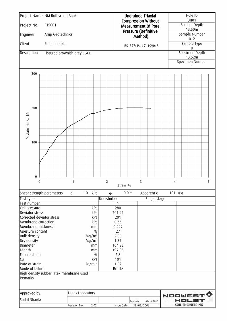
Description
Shear strength parameters c kPa φ ° Apparent c kPa
Undisturbed Single stage
Remarks
Approved by:
Print date
Revision No.
Rate of strainMode of failure
Test typeTest number
Dry densityDiameterLengthFailure strain
Corrected deviator stressMembrane correction
%kPa
Bulk density
mm%
mmmm
Membrane thicknessMoisture content
1.52Brittle
kPakPakPakPa
%/min
Mg/m3
Mg/m3
104.83197.03
2.8101
1280
201.422010.330.449
272.001.57
High density rubber latex membrane used
2.02 Issue Date 18/05/2006
Sushil Sharda 03/10/2007
Specimen Number1
Leeds Laboratory
Cu
BH01Sample Depth
Fissured brownish grey CLAY.U
Specimen Depth13.52m
BS1377: Part 7: 1990: 8
Engineer Arup Geotechnics
13.50mSample Number
Project Name NM Rothschild Bank
012Sample Type
Undrained Triaxial Undrained Triaxial Undrained Triaxial Undrained Triaxial Compression Without Compression Without Compression Without Compression Without Measurement Of Pore Measurement Of Pore Measurement Of Pore Measurement Of Pore Pressure (Definitive Pressure (Definitive Pressure (Definitive Pressure (Definitive
Method)Method)Method)Method)
Project No. F15001
Hole ID
Client Stanhope plc
101
Deviator stressCell pressure
101 0.0
0
100
200
300
0 1 2 3 4 5Strain %
Devi
ator st
ress
kP
a

Description
Shear strength parameters c kPa φ ° Apparent c kPa
Undisturbed Single stage
Remarks
Approved by:
Print date
Revision No.
Rate of strainMode of failure
Test typeTest number
Dry densityDiameterLengthFailure strain
Corrected deviator stressMembrane correction
%kPa
Bulk density
mm%
mmmm
Membrane thicknessMoisture content
2.03Brittle
kPakPakPakPa
%/min
Mg/m3
Mg/m3
104.47196.70
2.5109
1350
217.792180.200.302
272.041.61
High density rubber latex membrane used
2.02 Issue Date 18/05/2006
Sushil Sharda 03/10/2007
Specimen Number1
Leeds Laboratory
Cu
BH01Sample Depth
Fissured grey CLAY with silt lenses.U
Specimen Depth15.55m
BS1377: Part 7: 1990: 8
Engineer Arup Geotechnics
15.50mSample Number
Project Name NM Rothschild Bank
015Sample Type
Undrained Triaxial Undrained Triaxial Undrained Triaxial Undrained Triaxial Compression Without Compression Without Compression Without Compression Without Measurement Of Pore Measurement Of Pore Measurement Of Pore Measurement Of Pore Pressure (Definitive Pressure (Definitive Pressure (Definitive Pressure (Definitive
Method)Method)Method)Method)
Project No. F15001
Hole ID
Client Stanhope plc
109
Deviator stressCell pressure
109 0.0
0
100
200
300
0 1 2 3 4 5Strain %
Devi
ator st
ress
kP
a

Description
Shear strength parameters c kPa φ ° Apparent c kPa
Undisturbed Single stage
Remarks
Approved by:
Print date
Revision No.
Rate of strainMode of failure
Test typeTest number
Dry densityDiameterLengthFailure strain
Corrected deviator stressMembrane correction
%kPa
Bulk density
mm%
mmmm
Membrane thicknessMoisture content
1.52Compound
kPakPakPakPa
%/min
Mg/m3
Mg/m3
104.68197.10
4.3132
1400
264.382640.490.449
282.011.57
High density rubber latex membrane used
2.02 Issue Date 18/05/2006
Sushil Sharda 03/10/2007
Specimen Number1
Leeds Laboratory
Cu
BH01Sample Depth
Fissured brownish grey CLAY.U
Specimen Depth17.51m
BS1377: Part 7: 1990: 8
Engineer Arup Geotechnics
17.50mSample Number
Project Name NM Rothschild Bank
018Sample Type
Undrained Triaxial Undrained Triaxial Undrained Triaxial Undrained Triaxial Compression Without Compression Without Compression Without Compression Without Measurement Of Pore Measurement Of Pore Measurement Of Pore Measurement Of Pore Pressure (Definitive Pressure (Definitive Pressure (Definitive Pressure (Definitive
Method)Method)Method)Method)
Project No. F15001
Hole ID
Client Stanhope plc
132
Deviator stressCell pressure
132 0.0
0
100
200
300
0 5 10 15 20 25Strain %
Devi
ator st
ress
kP
a

Description
Shear strength parameters c kPa φ ° Apparent c kPa
Undisturbed Single stage
Remarks
Approved by:
Print date
Revision No.
Rate of strainMode of failure
Test typeTest number
Dry densityDiameterLengthFailure strain
Corrected deviator stressMembrane correction
%kPa
Bulk density
mm%
mmmm
Membrane thicknessMoisture content
1.53Brittle
kPakPakPakPa
%/min
Mg/m3
Mg/m3
104.47196.53
4.3127
1460
254.032540.490.449
281.931.51
High density rubber latex membrane used
2.02 Issue Date 18/05/2006
Sushil Sharda 03/10/2007
Specimen Number1
Leeds Laboratory
Cu
BH01Sample Depth
Fissured brown CLAY with silt lenses.U
Specimen Depth19.55m
BS1377: Part 7: 1990: 8
Engineer Arup Geotechnics
19.50mSample Number
Project Name NM Rothschild Bank
021Sample Type
Undrained Triaxial Undrained Triaxial Undrained Triaxial Undrained Triaxial Compression Without Compression Without Compression Without Compression Without Measurement Of Pore Measurement Of Pore Measurement Of Pore Measurement Of Pore Pressure (Definitive Pressure (Definitive Pressure (Definitive Pressure (Definitive
Method)Method)Method)Method)
Project No. F15001
Hole ID
Client Stanhope plc
127
Deviator stressCell pressure
127 0.0
0
100
200
300
0 1 2 3 4 5Strain %
Devi
ator st
ress
kP
a
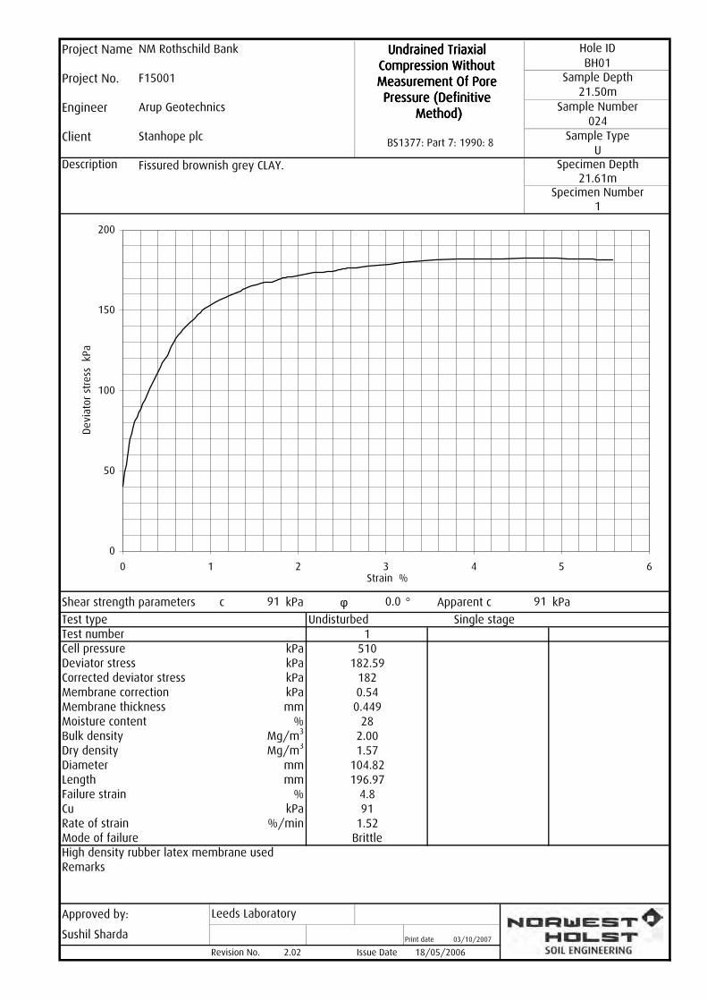
Description
Shear strength parameters c kPa φ ° Apparent c kPa
Undisturbed Single stage
Remarks
Approved by:
Print date
Revision No.
Rate of strainMode of failure
Test typeTest number
Dry densityDiameterLengthFailure strain
Corrected deviator stressMembrane correction
%kPa
Bulk density
mm%
mmmm
Membrane thicknessMoisture content
1.52Brittle
kPakPakPakPa
%/min
Mg/m3
Mg/m3
104.82196.97
4.891
1510
182.591820.540.449
282.001.57
High density rubber latex membrane used
2.02 Issue Date 18/05/2006
Sushil Sharda 03/10/2007
Specimen Number1
Leeds Laboratory
Cu
BH01Sample Depth
Fissured brownish grey CLAY.U
Specimen Depth21.61m
BS1377: Part 7: 1990: 8
Engineer Arup Geotechnics
21.50mSample Number
Project Name NM Rothschild Bank
024Sample Type
Undrained Triaxial Undrained Triaxial Undrained Triaxial Undrained Triaxial Compression Without Compression Without Compression Without Compression Without Measurement Of Pore Measurement Of Pore Measurement Of Pore Measurement Of Pore Pressure (Definitive Pressure (Definitive Pressure (Definitive Pressure (Definitive
Method)Method)Method)Method)
Project No. F15001
Hole ID
Client Stanhope plc
91
Deviator stressCell pressure
91 0.0
0
50
100
150
200
0 1 2 3 4 5 6Strain %
Devi
ator st
ress
kP
a

Description
Shear strength parameters c kPa φ ° Apparent c kPa
Undisturbed Single stage
Remarks
Approved by:
Print date
Revision No.
Rate of strainMode of failure
Test typeTest number
Dry densityDiameterLengthFailure strain
Corrected deviator stressMembrane correction
%kPa
Bulk density
mm%
mmmm
Membrane thicknessMoisture content
1.52Brittle
kPakPakPakPa
%/min
Mg/m3
Mg/m3
104.55196.77
2.3123
1560
246.422460.280.449
291.981.53
High density rubber latex membrane used
2.02 Issue Date 18/05/2006
Sushil Sharda 03/10/2007
Specimen Number1
Leeds Laboratory
Cu
BH01Sample Depth
Fissured greyish brown CLAY.U
Specimen Depth23.53m
BS1377: Part 7: 1990: 8
Engineer Arup Geotechnics
23.50mSample Number
Project Name NM Rothschild Bank
027Sample Type
Undrained Triaxial Undrained Triaxial Undrained Triaxial Undrained Triaxial Compression Without Compression Without Compression Without Compression Without Measurement Of Pore Measurement Of Pore Measurement Of Pore Measurement Of Pore Pressure (Definitive Pressure (Definitive Pressure (Definitive Pressure (Definitive
Method)Method)Method)Method)
Project No. F15001
Hole ID
Client Stanhope plc
123
Deviator stressCell pressure
123 0.0
0
100
200
300
0 1 2 3 4 5Strain %
Devi
ator st
ress
kP
a

Description
Shear strength parameters c kPa φ ° Apparent c kPa
Undisturbed Single stage
Remarks
Approved by:
Print date
Revision No.
Rate of strainMode of failure
Test typeTest number
Dry densityDiameterLengthFailure strain
Corrected deviator stressMembrane correction
%kPa
Bulk density
mm%
mmmm
Membrane thicknessMoisture content
2.03Brittle
kPakPakPakPa
%/min
Mg/m3
Mg/m3
104.95196.80
4.3142
1610
284.332840.490.449
281.991.55
High density rubber latex membrane used
2.02 Issue Date 18/05/2006
Sushil Sharda 03/10/2007
Specimen Number1
Leeds Laboratory
Cu
BH01Sample Depth
Fissured brown CLAY.U
Specimen Depth25.55m
BS1377: Part 7: 1990: 8
Engineer Arup Geotechnics
25.50mSample Number
Project Name NM Rothschild Bank
030Sample Type
Undrained Triaxial Undrained Triaxial Undrained Triaxial Undrained Triaxial Compression Without Compression Without Compression Without Compression Without Measurement Of Pore Measurement Of Pore Measurement Of Pore Measurement Of Pore Pressure (Definitive Pressure (Definitive Pressure (Definitive Pressure (Definitive
Method)Method)Method)Method)
Project No. F15001
Hole ID
Client Stanhope plc
142
Deviator stressCell pressure
142 0.0
0
100
200
300
0 1 2 3 4 5 6Strain %
Devi
ator st
ress
kP
a

Description
Shear strength parameters c kPa φ ° Apparent c kPa
Undisturbed Single stage
Remarks
Approved by:
Print date
Revision No.
Rate of strainMode of failure
Test typeTest number
Dry densityDiameterLengthFailure strain
Corrected deviator stressMembrane correction
%kPa
Bulk density
mm%
mmmm
Membrane thicknessMoisture content
1.52Brittle
kPakPakPakPa
%/min
Mg/m3
Mg/m3
102.85196.77
5.1266
1670
532.765320.570.449
232.111.71
High density rubber latex membrane used
2.02 Issue Date 18/05/2006
Stuart Kirk 03/10/2007
Specimen Number1
Leeds Laboratory
Cu
BH01Sample Depth
Fissured grey CLAY with silt lenses.U
Specimen Depth27.52m
BS1377: Part 7: 1990: 8
Engineer Arup Geotechnics
27.50mSample Number
Project Name NM Rothschild Bank
033Sample Type
Undrained Triaxial Undrained Triaxial Undrained Triaxial Undrained Triaxial Compression Without Compression Without Compression Without Compression Without Measurement Of Pore Measurement Of Pore Measurement Of Pore Measurement Of Pore Pressure (Definitive Pressure (Definitive Pressure (Definitive Pressure (Definitive
Method)Method)Method)Method)
Project No. F15001
Hole ID
Client Stanhope plc
266
Deviator stressCell pressure
266 0.0
0
100
200
300
400
500
600
0 1 2 3 4 5 6 7Strain %
Devi
ator st
ress
kP
a
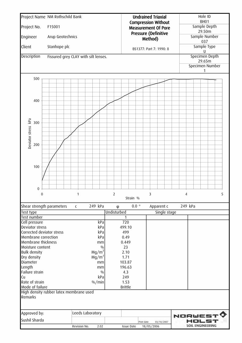
Description
Shear strength parameters c kPa φ ° Apparent c kPa
Undisturbed Single stage
Remarks
Approved by:
Print date
Revision No.
Rate of strainMode of failure
Test typeTest number
Dry densityDiameterLengthFailure strain
Corrected deviator stressMembrane correction
%kPa
Bulk density
mm%
mmmm
Membrane thicknessMoisture content
1.53Brittle
kPakPakPakPa
%/min
Mg/m3
Mg/m3
103.87196.63
4.3249
1720
499.104990.490.449
232.101.71
High density rubber latex membrane used
2.02 Issue Date 18/05/2006
Sushil Sharda 03/10/2007
Specimen Number1
Leeds Laboratory
Cu
BH01Sample Depth
Fissured grey CLAY with silt lenses.U
Specimen Depth29.65m
BS1377: Part 7: 1990: 8
Engineer Arup Geotechnics
29.50mSample Number
Project Name NM Rothschild Bank
037Sample Type
Undrained Triaxial Undrained Triaxial Undrained Triaxial Undrained Triaxial Compression Without Compression Without Compression Without Compression Without Measurement Of Pore Measurement Of Pore Measurement Of Pore Measurement Of Pore Pressure (Definitive Pressure (Definitive Pressure (Definitive Pressure (Definitive
Method)Method)Method)Method)
Project No. F15001
Hole ID
Client Stanhope plc
249
Deviator stressCell pressure
249 0.0
0
100
200
300
400
500
0 1 2 3 4 5Strain %
Devi
ator st
ress
kP
a

Description
Shear strength parameters c kPa φ ° Apparent c kPa
Undisturbed Single stage
Remarks
Approved by:
Print date
Revision No.
Rate of strainMode of failure
Test typeTest number
Dry densityDiameterLengthFailure strain
Corrected deviator stressMembrane correction
%kPa
Bulk density
mm%
mmmm
Membrane thicknessMoisture content
1.52Brittle
kPakPakPakPa
%/min
Mg/m3
Mg/m3
104.90196.80
5.6282
1760
565.535650.610.449
202.031.69
High density rubber latex membrane used
2.02 Issue Date 18/05/2006
Sushil Sharda 03/10/2007
Specimen Number1
Leeds Laboratory
Cu
BH01Sample Depth
Fissured brown sandy CLAY.U
Specimen Depth31.58m
BS1377: Part 7: 1990: 8
Engineer Arup Geotechnics
31.50mSample Number
Project Name NM Rothschild Bank
040Sample Type
Undrained Triaxial Undrained Triaxial Undrained Triaxial Undrained Triaxial Compression Without Compression Without Compression Without Compression Without Measurement Of Pore Measurement Of Pore Measurement Of Pore Measurement Of Pore Pressure (Definitive Pressure (Definitive Pressure (Definitive Pressure (Definitive
Method)Method)Method)Method)
Project No. F15001
Hole ID
Client Stanhope plc
282
Deviator stressCell pressure
282 0.0
0
100
200
300
400
500
600
0 1 2 3 4 5 6 7Strain %
Devi
ator st
ress
kP
a
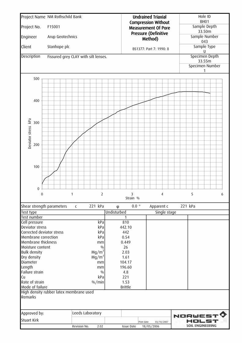
Description
Shear strength parameters c kPa φ ° Apparent c kPa
Undisturbed Single stage
Remarks
Approved by:
Print date
Revision No.
Rate of strainMode of failure
Test typeTest number
Dry densityDiameterLengthFailure strain
Corrected deviator stressMembrane correction
%kPa
Bulk density
mm%
mmmm
Membrane thicknessMoisture content
1.53Brittle
kPakPakPakPa
%/min
Mg/m3
Mg/m3
104.17196.60
4.8221
1810
442.104420.540.449
262.031.61
High density rubber latex membrane used
2.02 Issue Date 18/05/2006
Stuart Kirk 03/10/2007
Specimen Number1
Leeds Laboratory
Cu
BH01Sample Depth
Fissured grey CLAY with silt lenses.U
Specimen Depth33.55m
BS1377: Part 7: 1990: 8
Engineer Arup Geotechnics
33.50mSample Number
Project Name NM Rothschild Bank
043Sample Type
Undrained Triaxial Undrained Triaxial Undrained Triaxial Undrained Triaxial Compression Without Compression Without Compression Without Compression Without Measurement Of Pore Measurement Of Pore Measurement Of Pore Measurement Of Pore Pressure (Definitive Pressure (Definitive Pressure (Definitive Pressure (Definitive
Method)Method)Method)Method)
Project No. F15001
Hole ID
Client Stanhope plc
221
Deviator stressCell pressure
221 0.0
0
100
200
300
400
500
0 1 2 3 4 5 6Strain %
Devi
ator st
ress
kP
a

Description
Shear strength parameters c kPa φ ° Apparent c kPa
Undisturbed Single stage
Remarks
Approved by:
Print date
Revision No.
Rate of strainMode of failure
Test typeTest number
Dry densityDiameterLengthFailure strain
Corrected deviator stressMembrane correction
%kPa
Bulk density
mm%
mmmm
Membrane thicknessMoisture content
1.02Brittle
kPakPakPakPa
%/min
Mg/m3
Mg/m3
104.98196.57
2.2155
1860
310.673100.270.449
262.001.59
High density rubber latex membrane used
2.02 Issue Date 18/05/2006
Sushil Sharda 03/10/2007
Specimen Number1
Leeds Laboratory
Cu
BH01Sample Depth
Fissured brown CLAY.U
Specimen Depth35.57m
BS1377: Part 7: 1990: 8
Engineer Arup Geotechnics
35.50mSample Number
Project Name NM Rothschild Bank
046Sample Type
Undrained Triaxial Undrained Triaxial Undrained Triaxial Undrained Triaxial Compression Without Compression Without Compression Without Compression Without Measurement Of Pore Measurement Of Pore Measurement Of Pore Measurement Of Pore Pressure (Definitive Pressure (Definitive Pressure (Definitive Pressure (Definitive
Method)Method)Method)Method)
Project No. F15001
Hole ID
Client Stanhope plc
155
Deviator stressCell pressure
155 0.0
0
100
200
300
400
0 1 2 3 4 5Strain %
Devi
ator st
ress
kP
a

Description
Shear strength parameters c kPa φ ° Apparent c kPa
Undisturbed Single stage
Remarks
Approved by:
Print date
Revision No.
Rate of strainMode of failure
Test typeTest number
Dry densityDiameterLengthFailure strain
Corrected deviator stressMembrane correction
%kPa
Bulk density
mm%
mmmm
Membrane thicknessMoisture content
1.53Brittle
kPakPakPakPa
%/min
Mg/m3
Mg/m3
104.12196.23
3.3256
1900
513.205130.390.449
271.951.54
High density rubber latex membrane used
2.02 Issue Date 18/05/2006
Sushil Sharda 03/10/2007
Specimen Number1
Leeds Laboratory
Cu
BH01Sample Depth
Fissured brownish grey CLAY.U
Specimen Depth37.70m
BS1377: Part 7: 1990: 8
Engineer Arup Geotechnics
37.50mSample Number
Project Name NM Rothschild Bank
049Sample Type
Undrained Triaxial Undrained Triaxial Undrained Triaxial Undrained Triaxial Compression Without Compression Without Compression Without Compression Without Measurement Of Pore Measurement Of Pore Measurement Of Pore Measurement Of Pore Pressure (Definitive Pressure (Definitive Pressure (Definitive Pressure (Definitive
Method)Method)Method)Method)
Project No. F15001
Hole ID
Client Stanhope plc
256
Deviator stressCell pressure
256 0.0
0
100
200
300
400
500
600
0 1 2 3 4 5Strain %
Devi
ator st
ress
kP
a

Description
Shear strength parameters c kPa φ ° Apparent c kPa
Undisturbed Single stage
Remarks
Approved by:
Print date
Revision No.
Rate of strainMode of failure
Test typeTest number
Dry densityDiameterLengthFailure strain
Corrected deviator stressMembrane correction
%kPa
Bulk density
mm%
mmmm
Membrane thicknessMoisture content
1.02Brittle
kPakPakPakPa
%/min
Mg/m3
Mg/m3
104.12196.63
3.1169
1940
337.413370.240.302
252.001.60
High density rubber latex membrane used
2.02 Issue Date 18/05/2006
Sushil Sharda 03/10/2007
Specimen Number1
Leeds Laboratory
Cu
BH01Sample Depth
Fissured grey CLAY with silt lenses.U
Specimen Depth39.63m
BS1377: Part 7: 1990: 8
Engineer Arup Geotechnics
39.50mSample Number
Project Name NM Rothschild Bank
052Sample Type
Undrained Triaxial Undrained Triaxial Undrained Triaxial Undrained Triaxial Compression Without Compression Without Compression Without Compression Without Measurement Of Pore Measurement Of Pore Measurement Of Pore Measurement Of Pore Pressure (Definitive Pressure (Definitive Pressure (Definitive Pressure (Definitive
Method)Method)Method)Method)
Project No. F15001
Hole ID
Client Stanhope plc
169
Deviator stressCell pressure
169 0.0
0
100
200
300
400
0 1 2 3 4 5Strain %
Devi
ator st
ress
kP
a

Description
Shear strength parameters c kPa φ ° Apparent c kPa
Undisturbed Single stage
Remarks
Approved by:
Print date
Revision No.
Rate of strainMode of failure
Test typeTest number
Dry densityDiameterLengthFailure strain
Corrected deviator stressMembrane correction
%kPa
Bulk density
mm%
mmmm
Membrane thicknessMoisture content
2.03Brittle
kPakPakPakPa
%/min
Mg/m3
Mg/m3
104.83196.97
2.8183
1990
366.683660.330.449
251.971.58
High density rubber latex membrane used
2.02 Issue Date 18/05/2006
Sushil Sharda 03/10/2007
Specimen Number1
Leeds Laboratory
Cu
BH01Sample Depth
Fissured grey CLAY with silt lenses.U
Specimen Depth41.62m
BS1377: Part 7: 1990: 8
Engineer Arup Geotechnics
41.50mSample Number
Project Name NM Rothschild Bank
055Sample Type
Undrained Triaxial Undrained Triaxial Undrained Triaxial Undrained Triaxial Compression Without Compression Without Compression Without Compression Without Measurement Of Pore Measurement Of Pore Measurement Of Pore Measurement Of Pore Pressure (Definitive Pressure (Definitive Pressure (Definitive Pressure (Definitive
Method)Method)Method)Method)
Project No. F15001
Hole ID
Client Stanhope plc
183
Deviator stressCell pressure
183 0.0
0
100
200
300
400
0 1 2 3 4 5Strain %
Devi
ator st
ress
kP
a

Description
Shear strength parameters c kPa φ ° Apparent c kPa
Undisturbed Single stage
Remarks
Approved by:
Print date
Revision No.
Rate of strainMode of failure
Test typeTest number
Dry densityDiameterLengthFailure strain
Corrected deviator stressMembrane correction
%kPa
Bulk density
mm%
mmmm
Membrane thicknessMoisture content
1.02Brittle
kPakPakPakPa
%/min
Mg/m3
Mg/m3
105.38196.43
6.1243
11030
485.804850.650.449
251.961.57
High density rubber latex membrane used
2.02 Issue Date 18/05/2006
Sushil Sharda 03/10/2007
Specimen Number1
Leeds Laboratory
Cu
BH01Sample Depth
Fissured brown sandy CLAY.U
Specimen Depth43.55m
BS1377: Part 7: 1990: 8
Engineer Arup Geotechnics
43.50mSample Number
Project Name NM Rothschild Bank
058Sample Type
Undrained Triaxial Undrained Triaxial Undrained Triaxial Undrained Triaxial Compression Without Compression Without Compression Without Compression Without Measurement Of Pore Measurement Of Pore Measurement Of Pore Measurement Of Pore Pressure (Definitive Pressure (Definitive Pressure (Definitive Pressure (Definitive
Method)Method)Method)Method)
Project No. F15001
Hole ID
Client Stanhope plc
243
Deviator stressCell pressure
243 0.0
0
100
200
300
400
500
0 1 2 3 4 5 6 7Strain %
Devi
ator st
ress
kP
a

Description
Shear strength parameters c kPa φ ° Apparent c kPa
Undisturbed Single stage
Remarks
Approved by:
Print date
Revision No.
Rate of strainMode of failure
Test typeTest number
Dry densityDiameterLengthFailure strain
Corrected deviator stressMembrane correction
%kPa
Bulk density
mm%
mmmm
Membrane thicknessMoisture content
1.02Brittle
kPakPakPakPa
%/min
Mg/m3
Mg/m3
104.97197.00
6.6341
11080
683.056820.700.449
241.971.59
High density rubber latex membrane used
2.02 Issue Date 18/05/2006
Sushil Sharda 03/10/2007
Specimen Number1
Leeds Laboratory
Cu
BH01Sample Depth
Fissured greyish brown CLAY. U
Specimen Depth45.61m
BS1377: Part 7: 1990: 8
Engineer Arup Geotechnics
45.50mSample Number
Project Name NM Rothschild Bank
061Sample Type
Undrained Triaxial Undrained Triaxial Undrained Triaxial Undrained Triaxial Compression Without Compression Without Compression Without Compression Without Measurement Of Pore Measurement Of Pore Measurement Of Pore Measurement Of Pore Pressure (Definitive Pressure (Definitive Pressure (Definitive Pressure (Definitive
Method)Method)Method)Method)
Project No. F15001
Hole ID
Client Stanhope plc
341
Deviator stressCell pressure
341 0.0
0
100
200
300
400
500
600
700
0 1 2 3 4 5 6 7Strain %
Devi
ator st
ress
kP
a


SUPPORTING FACTUAL DATA
SECTION CLaboratory Testing
CONTAMINATION TEST RESULTS


SUPPORTING FACTUAL DATA
SECTION DSite Plans
SITE LOCATION PLAN

Reproduced from Ordnance Survey's 1:50,000 map number 177 with the permission ofthe Controller of Her Majesty's Stationery Office, Crown copyright reserved Licence Number: AL52185A0001
Date
Form No. Revision No. 2.01SI SLP
Scale
13/11/2007
Issue Date
Project Name NMR BANK Site Location Plan
16/03/2006
Project No.
Engineer
Client
1:50,000
01
Fig no.
F15001
Arup Geotechnics
Stanhope Plc
Denotes Site Location

SUPPORTING FACTUAL DATA
SECTION DSite Plans
EXPLORATORY HOLELOCATION PLAN
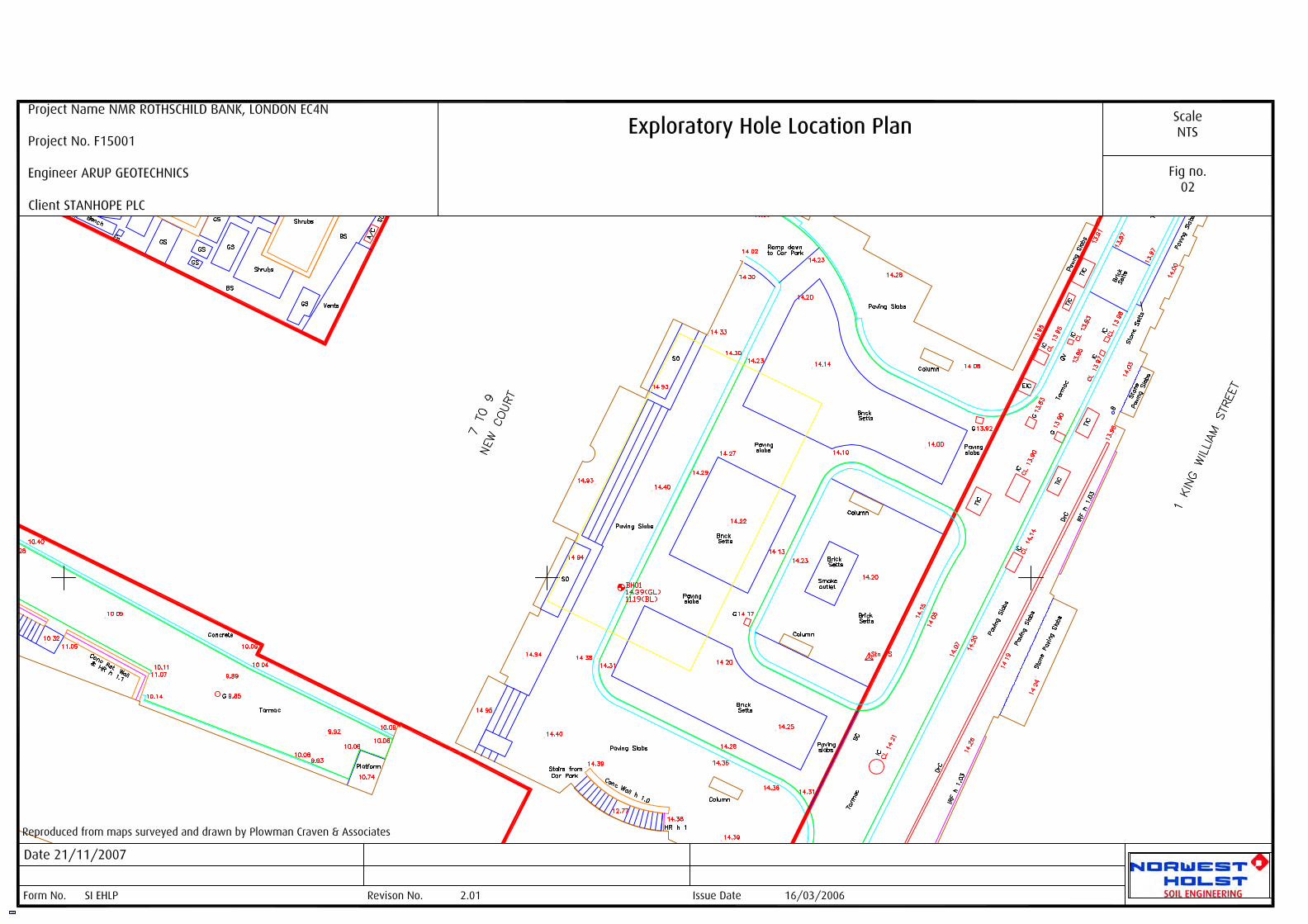

SUPPORTING FACTUAL DATA
SECTION EPhotographs
INSPECTION PIT / TRIAL PIT /TRIAL TRENCH PHOTOGRAPHS
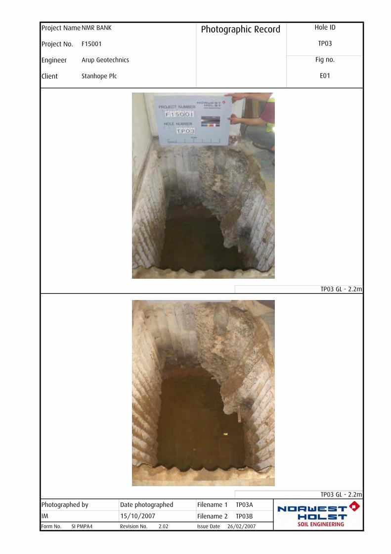
Photographed by Date photographed Filename 1 TP03A
Filename 2 TP03B
Form No. SI PMPA4 Revision No.
Project Name NMR BANK Photographic Record Hole ID
TP03Project No. F15001
Engineer Arup Geotechnics Fig no.
E01Client Stanhope Plc
TP03 GL - 2.2m
TP03 GL - 2.2m
IM 15/10/2007
2.02 Issue Date 26/02/2007

1. Head Office &Geotechnical Laboratory Parkside Lane,Dewsbury Road,LeedsLS11 5SX
Tel: 0113 271 1111Fax: 0113 276 0472
2. Scottish Office &Geotechnical Laboratory Unit 4, 28 Firth Road,Houston Industrial Est,Livingston, West LothianEH54 5DJ
Tel: 01506 434300Fax: 01506 442593
3. Southern Office
Astral House, Imperial Way, Watford,HertfordshireWD24 4WW
Tel: 01923 204040Fax: 01923 204069
Additional Offices
Bristol, Widnes and Dublin