a versatile networked sensing system as add-on system for
TRANSCRIPT
A Versatile Networked Sensing System as Add-OnSystem for Augmenting Sports Devices
Andreas Kräss, Matthias KranzResearch Group Embedded Interaction
Amalienstrasse 17, 80333 Munich, Germany{andreas,matthias}@hcilab.org
Abstract— In this paper, we present a novel sensing platformfor training support in sports. Ubiquitous computing applicationshave been especially interesting for this area as sensing technolo-gies allow unobtrusive integration and for information acquisitionthat formerly was not possible. The developed networked sensingsystem can be attached to any piece of sports equipment thateither has an axis of rotation, e.g. a gear box or a beltsystem. We specifically target at high-priced sports equipmentfor sports schools and fitness studios. Here, often no integratedmeasurements systems are available, despite the high price ofthe robust machines. We present the sensor device, the overallsystem architecture and the algorithms to convert accelerationinto Joule, a unit of great importance to trainees.
I. INTRODUCTION
During the development process, we could incorporate ourexperience of designing ubiquitous computing systems in thefield of sports [1]–[4]. The focus of this work though doesnot lie in the design and development process as in our earlierwork [5], but on a flexible networked sensing platform fora great variety of sports devices. The sensor system and thealgorithms can, with out any change, be used for any existingpiece of sports equipment that either has an axis or usesrotation like the synchronous training machine (see Fig. 1) oruses belts or cords to translate motions of training machines.
The advantage compared to existing sensor-augmented sys-tems that usually have sensor system e.g. in a gear box ofthe sports device is that our system can be used as add-on.This has several advantages: usually manufactures do chargea significant amount of money for the inclusion of sensorsin gearboxes due e.g. the complexity of manufacturing andadditionally software systems from the same manufacturerhave to be obtained. This often results in data conversionproblems between these systems and existing training systemsthat already exist e.g. in a sports school. Easy integration e.g.for automatic training analysis and training plan generation arethus additionally costly, if even possible. Our system allowseasy bindings to existing training systems and integration withthe additional benefit that our sensor box can be attachedoutside the training device and also to training devices thatare not yet sensor augmented by the original manufacturer.
For a comprising discussion of related work of sensingsystems we would like to refer the reader to [6].
II. SYSTEM DESCRIPTION
The system consists of a sensor device for measuring anangle of a lever or belt running over an axis by a twoaxes acceleration sensor and a middleware for processing
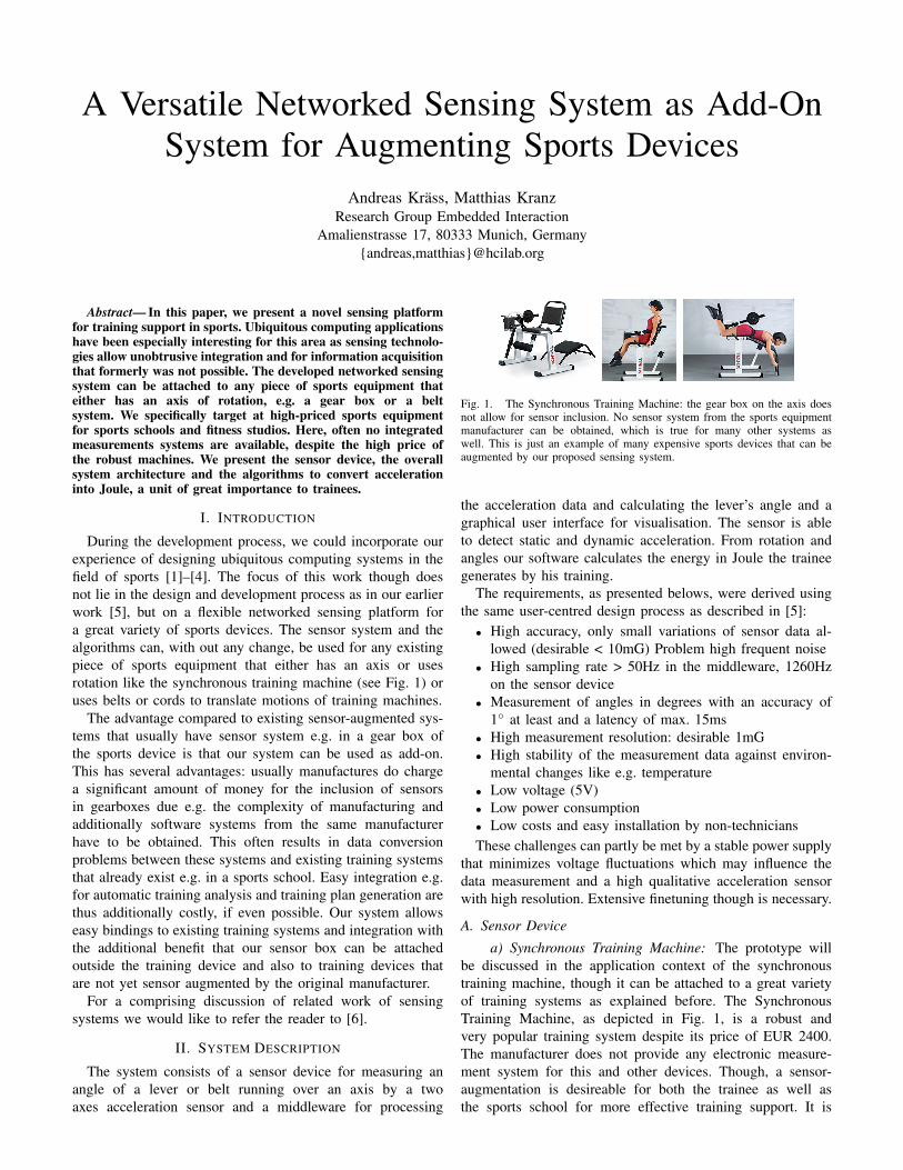
Fig. 1. The Synchronous Training Machine: the gear box on the axis doesnot allow for sensor inclusion. No sensor system from the sports equipmentmanufacturer can be obtained, which is true for many other systems aswell. This is just an example of many expensive sports devices that can beaugmented by our proposed sensing system.
the acceleration data and calculating the lever’s angle and agraphical user interface for visualisation. The sensor is ableto detect static and dynamic acceleration. From rotation andangles our software calculates the energy in Joule the traineegenerates by his training.
The requirements, as presented belows, were derived usingthe same user-centred design process as described in [5]:
• High accuracy, only small variations of sensor data al-lowed (desirable < 10mG) Problem high frequent noise
• High sampling rate > 50Hz in the middleware, 1260Hzon the sensor device
• Measurement of angles in degrees with an accuracy of1◦ at least and a latency of max. 15ms
• High measurement resolution: desirable 1mG• High stability of the measurement data against environ-
mental changes like e.g. temperature• Low voltage (5V)• Low power consumption• Low costs and easy installation by non-techniciansThese challenges can partly be met by a stable power supply
that minimizes voltage fluctuations which may influence thedata measurement and a high qualitative acceleration sensorwith high resolution. Extensive finetuning though is necessary.
A. Sensor Device
a) Synchronous Training Machine: The prototype willbe discussed in the application context of the synchronoustraining machine, though it can be attached to a great varietyof training systems as explained before. The SynchronousTraining Machine, as depicted in Fig. 1, is a robust andvery popular training system despite its price of EUR 2400.The manufacturer does not provide any electronic measure-ment system for this and other devices. Though, a sensor-augmentation is desireable for both the trainee as well asthe sports school for more effective training support. It is
surprising that e.g. ergometers can be obtained with muchelaborate sensor and system support even for consumers for acouple of hundred Euros but not for a high-priced professionaltraining system. This can partially be attributed to the amountof regulations and associated costs that a electronic device hasto comply to, e.g. from a safety point of view, to be allowedfor sale.
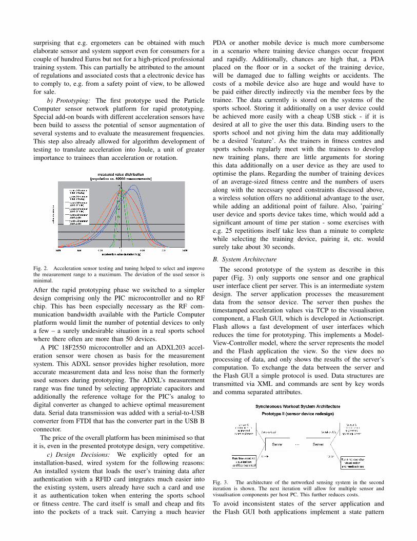
b) Prototyping: The first prototype used the ParticleComputer sensor network platform for rapid prototyping.Special add-on boards with different acceleration sensors havebeen build to assess the potential of sensor augmentation ofseveral systems and to evaluate the measurement frequencies.This step also already allowed for algorithm development oftesting to translate acceleration into Joule, a unit of greaterimportance to trainees than acceleration or rotation.
Fig. 2. Acceleration sensor testing and tuning helped to select and improvethe measurement range to a maximum. The deviation of the used sensor isminimal.
After the rapid prototyping phase we switched to a simplerdesign comprising only the PIC microcontroller and no RFchip. This has been especially necessary as the RF com-munication bandwidth available with the Particle Computerplatform would limit the number of potential devices to onlya few – a surely undesirable situation in a real sports schoolwhere there often are more than 50 devices.
A PIC 18F2550 microcontroller and an ADXL203 accel-eration sensor were chosen as basis for the measurementsystem. This ADXL sensor provides higher resolution, moreaccurate measurement data and less noise than the formerlyused sensors during prototyping. The ADXL’s measurementrange was fine tuned by selecting appropriate capacitors andadditionally the reference voltage for the PIC’s analog todigital converter as changed to achieve optimal measurementdata. Serial data transmission was added with a serial-to-USBconverter from FTDI that has the converter part in the USB Bconnector.
The price of the overall platform has been minimised so thatit is, even in the presented prototype design, very competitive.
c) Design Decisions: We explicitly opted for aninstallation-based, wired system for the following reasons:An installed system that loads the user’s training data afterauthentication with a RFID card integrates much easier intothe existing system, users already have such a card and useit as authentication token when entering the sports schoolor fitness centre. The card itself is small and cheap and fitsinto the pockets of a track suit. Carrying a much heavier
PDA or another mobile device is much more cumbersomein a scenario where training device changes occur frequentand rapidly. Additionally, chances are high that, a PDAplaced on the floor or in a socket of the training device,will be damaged due to falling weights or accidents. Thecosts of a mobile device also are huge and would have tobe paid either directly indirectly via the member fees by thetrainee. The data currently is stored on the systems of thesports school. Storing it additionally on a user device couldbe achieved more easily with a cheap USB stick - if it isdesired at all to give the user this data. Binding users to thesports school and not giving him the data may additionallybe a desired ’feature’. As the trainers in fitness centres andsports schools regularly meet with the trainees to developnew training plans, there are little arguments for storingthis data additionally on a user device as they are used tooptimise the plans. Regarding the number of training devicesof an average-sized fitness centre and the numbers of usersalong with the necessary speed constraints discussed above,a wireless solution offers no additional advantage to the user,while adding an additional point of failure. Also, ’pairing’user device and sports device takes time, which would add asignificant amount of time per station - some exercises withe.g. 25 repetitions itself take less than a minute to completewhile selecting the training device, pairing it, etc. wouldsurely take about 30 seconds.
B. System Architecture
The second prototype of the system as describe in thispaper (Fig. 3) only supports one sensor and one graphicaluser interface client per server. This is an intermediate systemdesign. The server application processes the measurementdata from the sensor device. The server then pushes thetimestamped acceleration values via TCP to the visualisationcomponent, a Flash GUI, which is developed in Actionscript.Flash allows a fast development of user interfaces whichreduces the time for prototyping. This implements a Model-View-Controller model, where the server represents the modeland the Flash application the view. So the view does noprocessing of data, and only shows the results of the server’scomputation. To exchange the data between the server andthe Flash GUI a simple protocol is used. Data structures aretransmitted via XML and commands are sent by key wordsand comma separated attributes.
Fig. 3. The architecture of the networked sensing system in the seconditeration is shown. The next iteration will allow for multiple sensor andvisualisation components per host PC. This further reduces costs.
To avoid inconsistent states of the server application andthe Flash GUI both applications implement a state pattern
for the communication. The behaviour of e.g. the server’sConnection object is realized by several states. The Connectionobject is responsible for the protocol and the applicationflow. Fig. 4 depicts the system design in UML. The statesavoid inconsistent program states, even if an implementationerror would exists i.e. in the protocol by an key word in anunexpected situation the server wouldn’t crash because theserver accepts in each state only certain instructions. Theprogram flow is also regulated by the state pattern, i.e. themeasurement values of the sensor are only processed in theTraining state. Each state also represents a certain screen inthe Flash application. Thus it is very easy to add new statesto extend the application and new GUI screens.
Fig. 4. The architecture was realized using state patterns. This assures thateven in case of system failure or transmission errors the state of the applicationis always defined.
d) GUI: The fist prototype used a database the adminis-trate, the athletes data, like the workout plan which includestraining milestones, progression rates of weight and work anda repository for the workout data to analyse the workoutprogression by a trainer. In the database are the processedmeasurement data of a workout session saved to analyse themto gain information of the training’s efficiency. Also a longterm observation of the athlete’s condition progress is possible.This will increase the long term motivation of the athletes. Thesecond prototype abandons on the database connection to sim-plify and speed up the application development to collect userexperience with the graphical user interface and the providedvisual feedback. The next prototype will include a furtherdevelopment of the database connection and functionality.
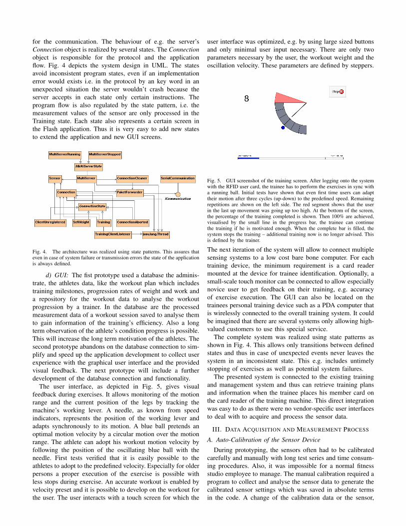
The user interface, as depicted in Fig. 5, gives visualfeedback during exercises. It allows monitoring of the motionrange and the current position of the legs by tracking themachine’s working lever. A needle, as known from speedindicators, represents the position of the working lever andadapts synchronously to its motion. A blue ball pretends anoptimal motion velocity by a circular motion over the motionrange. The athlete can adopt his workout motion velocity byfollowing the position of the oscillating blue ball with theneedle. First tests verified that it is easily possible to theathletes to adopt to the predefined velocity. Especially for olderpersons a proper execution of the exercise is possible withless stops during exercise. An accurate workout is enabled byvelocity preset and it is possible to develop on the workout forthe user. The user interacts with a touch screen for which the
user interface was optimized, e.g. by using large sized buttonsand only minimal user input necessary. There are only twoparameters necessary by the user, the workout weight and theoscillation velocity. These parameters are defined by steppers.
Fig. 5. GUI screenshot of the training screen. After logging onto the systemwith the RFID user card, the trainee has to perform the exercises in sync witha running ball. Initial tests have shown that even first time users can adapttheir motion after three cycles (up-down) to the predefined speed. Remainingrepetitions are shown on the left side. The red segment shows that the userin the last up movement was going up too high. At the bottom of the screen,the percentage of the training completed is shown. Then 100% are achieved,visualised by the small line in the progress bar, the trainee can continuethe training if he is motivated enough. When the complete bar is filled, thesystem stops the training – additional training now is no longer advised. Thisis defined by the trainer.
The next iteration of the system will allow to connect multiplesensing systems to a low cost bare bone computer. For eachtraining device, the minimum requirement is a card readermounted at the device for trainee identification. Optionally, asmall-scale touch monitor can be connected to allow especiallynovice user to get feedback on their training, e.g. accuracyof exercise execution. The GUI can also be located on thetrainees personal training device such as a PDA computer thatis wirelessly connected to the overall training system. It couldbe imagined that there are several systems only allowing high-valued customers to use this special service.
The complete system was realized using state patterns asshown in Fig. 4. This allows only transitions between definedstates and thus in case of unexpected events never leaves thesystem in an inconsistent state. This e.g. includes untimelystopping of exercises as well as potential system failures.
The presented system is connected to the existing trainingand management system and thus can retrieve training plansand information when the trainee places his member card onthe card reader of the training machine. This direct integrationwas easy to do as there were no vendor-specific user interfacesto deal with to acquire and process the sensor data.
III. DATA ACQUISITION AND MEASUREMENT PROCESS
A. Auto-Calibration of the Sensor Device
During prototyping, the sensors often had to be calibratedcarefully and manually with long test series and time consum-ing procedures. Also, it was impossible for a normal fitnessstudio employee to manage. The manual calibration required aprogram to collect and analyse the sensor data to generate thecalibrated sensor settings which was saved in absolute termsin the code. A change of the calibration data or the sensor,

e.g. for a second prototype the sensor would have slightlydifferent characteristics, required a recompilation of the codeto potentiate the changes.
The developed algorithm for self-calibration works as fol-lows. The system is collecting and storing each 1000 accel-eration measurement data in horizontal and vertical position.It is thereby possible to determine the 0g and the 1g levelof each axis. The data’s average, which is equivalent to theexpected value in practice, the variance and the root meansquare deviation are calculated. Thereby it is possible to detectvibrations during calibration. If there is no clear main peak inthe occurrence, and the root mean square deviation is to large,this could be easily detected and the calibration has to berepeated. If the vibration level is low, the pre-analysed data issaved. The calibration routine allows to detect in which wayit was mounted to the axis and thus allows a “stick-and-go”approach. This is necessary to allow a non-technician to setupand install the system. The system automatically detects whichaxis is, in case of the Synchronous Training Machine, parallelto the level and which is perpendicular to it. A label on thebox additionally visualises the correct mounting as backup.
B. Algorithms for Data Processing
First the acceleration data are averaged for the first timeon the PIC over five values to smooth the coarsest noise.By sampling the data it is necessary to maintain a certainsampling rate. Each sensor type has a certain working fre-quency which specifies the maximum sampling rate. Thissampling rate mustn’t be crossed, because this results largevariations otherwise. At the ADXL203 two certain condensersbetween the data conductor pathes and ground are neededthat influence the sampling rate and have to be adapted toit. At this sensor device, 3.9nF are chosen to reach a samplingrate of 1260Hz on the sensor device. This results in about8ms for sampling and about 5ms for data transmission to thecomputer by 115200 Baud. So a data rate of about 76Hz isreached. The PIC only measures the the acceleration values,averages them over five values and sends them to the serverapplication. This application post-processes the values by afloating average over ten values. Then the angle is calculatedby a simple tangent. All other data like velocity, with help ofthe timestamps, or work, by calculating the difference fromthe current angle and the last local extrema are calculated. Allthe postprocessing is done on the server application, becauseit has more resources than the PIC, especially the calculationof floating point arithmetic and long integers is much faster.The advantage of this two step data processing is a relativelow development effort on the PIC.
There exists a trade-off between accuracy and latency. Themore accurate the measurements are needed, the merrier valuesare needed for the floating average and the merrier largeris the delay. All this trade-off factors are optimised for thismeasurement system, which is developed, to reach an accuracyof more than 1◦.
C. Converting acceleration in Joule
The raw acceleration data are worthless for the athletes.I.e. the current power, the athlete produces during workouthas more significance for feedback. The user should do their
exercises in an certain power range. A certain algorithm hasbeen developed to calculate Joules from the acceleration data.First the acceleration data are converted to angle values of themachine’s working lever which corresponds to the leg anglebetween femoral and shank. In a next step the current workneeds to be calculated, which is then related to the timestampsto achieve power data. The current work is calculated by theheight difference, which the weight overrides. By doing theexercise a second lever at the machine with the weight isactuated by a gear box with the working lever. The weightis lifted and lowered in a vertical circular way. For the workcalculation the local extrema in height are necessary. They arefound by a floating window which moves across queued anglevalues. The work results by the difference in weight height ofthe last extrema and the current angel. To gain current powervalues the work is correlated with the timestamps.
acceleration x, y -> angleAlpha = tan(x/y)extremaAngle(found by floating window), currentAnglecurrentHeight = leverLength ∗ sin(currentAngle)−1
extremaHeight = leverLength ∗ sin(extremaAngle)−1
deltaHeight = abs(extremaHeight− currentHeight)work = weight ∗ 9, 81 ∗ deltaHeightpower = work/(currentT ime− extremaTime)
Generally this conversion of acceleration data to power datais possible because of the exact measurement technique whichis used here. In most real world applications it is necessary toprocess the acceleration data to other physical quantities whichare more familiar to the current user’s situation, especially forgiving feedback.
IV. CONCLUSIONS AND FUTURE WORK
We present a novel sensor device for a great variety of sportsdevices that by today no measurement system exists for. Thealgorithms allow for fast and accurate data acquisition andprocessing. Acceleration information is converted to Joule, aunit of great importance for trainees. This conversion so farhas not been reported on.
The presented system is currently produced in zero-seriesand under real-world evaluation in a sports school. Future de-velopment will concentrate on multi-sensor and multi-displayintegration on one host PC.
REFERENCES
[1] M. Kranz, P. Holleis, W. Spiessl, and A. Schmidt, “The Therapy Top Mea-surement and Visualization System – An Example for the Advancementsin Existing Sports Equipments,” in Sport und Informatik IX. Proceedingsof the 6th Workshop of the dvs-Section Computer Science in Sport.Shaker, June 2006, pp. 201–210.
[2] Research Group Embedded Interaction, “UbiFitness Project Page,” http://www.hcilab.org/projects/ubifitness/, visited June 2006, June 2006.
[3] M. Kranz, “Designing Systems of Ubiquitous Sports Equipment (Re-search Video),” Adjungt Proceedings of Ubicomp 2006, Sep 2006.
[4] M. Kranz, P. Holleis, W. Spiessl, and A. Schmidt, “The Therapy TopMeasurement and Visualization System - An Example for the Advance-ments in Existing Sports Equipments,” International Journal of ComputerScience in Sport, vol. 5, no. 2, pp. 76–80, December 2006.
[5] M. Kranz, W. Spiessl, and A. Schmidt, “Designing ubiquitous computingsystems for sports equipment,” in Percom 2007.
[6] E. H. Chi, G. Borriello, G. Hunt, and N. Davies, “Sports technologies,”IEEE Pervasive Computing, Special Issue On Mobile And UbiquitousSystems, 2005.