a universal approach for the intuitive control of mobile robots using an ar/vr-based interface
TRANSCRIPT
Abstract—Mobile robots are used in a large field of scenarios,
like exploring contaminated areas, repairing oil rigs under water, finding survivors in collapsed buildings, etc. Currently, there is no unified intuitive user interface (UI) to control such complex mobile robots. As a consequence, some scenarios are done without the exploitation of experience and intuition of human teleoperators.
A novel framework has been developed to embed a flexible and modular UI into a complete 3-D virtual reality simulation system. This new approach wants to access maximum benefits of human operators. Sensor information received from the robot is prepared for an intuitive visualization. Virtual reality metaphors support the operator in his decisions. These metaphors are integrated into a real time stereo video stream. This approach is not restricted to any specific type of mobile robot and allows for the operation of different robot types with a consistent concept and user interface.
Keywords—3-D simulation system, augmented reality, teleoperation of mobile robots, user interface.
I. INTRODUCTION MPROVEMENTS in miniaturization and processing power allow for complex mobile robots equipped with plenty of
sensors. The operation of such robots and the preparation of the gathered information for a human operator are complex and project specific tasks.
In this paper, a novel framework for a flexible and intuitive user interface for mobile robots is presented. With this user interface, which is not restricted to a specific mobile robot, an approach is offered for the operator to easily teleoperate mobile robots and to visualize fused sensor information.
Nowadays, mobile robots allow for covering a wide area of activities. In particular, applications are emerging for mobile robots in exploration and rescue operations. For example, teleoperated submarine drones are inspecting and repairing oil rigs and undersea cables. In contaminated areas, mobile robots
Juergen Rossmann heads the Institute of Man-Machine Interaction, RWTH Aachen University, 52074 Aachen, Germany (e-mail: [email protected]).
Andre Kupetz is with the Dortmunder Initiative zur rechnerintegrierten Fertigung, Department Robot Technology, Dortmund, 44227 Germany (phone: +49-231-9700-778; fax: +49-231-9700-771; e-mail: [email protected]).
Roland Wischnewski is with the Dortmunder Initiative zur rechnerintegrierten Fertigung, Department Robot Technology, Dortmund, 44227 Germany (e-mail: [email protected]).
can be equipped with sensors to collect information about special gas densities or radioactivity. Furthermore, gas explosions or acts of terrorism may lead to enormous damage to buildings where mobile robots can search for survivors. In contrast to contaminated areas which might still be quite accessible, the terrain in the latter example is very likely to be inaccessible with conventional wheel driven robots. Thus, very different types of mobile robots concerning the locomotion and interaction are required. In all scenarios, the active exploration of the danger zone is a critical and difficult but necessary task for a precise localization of victims or points of interest and for a successful operation.
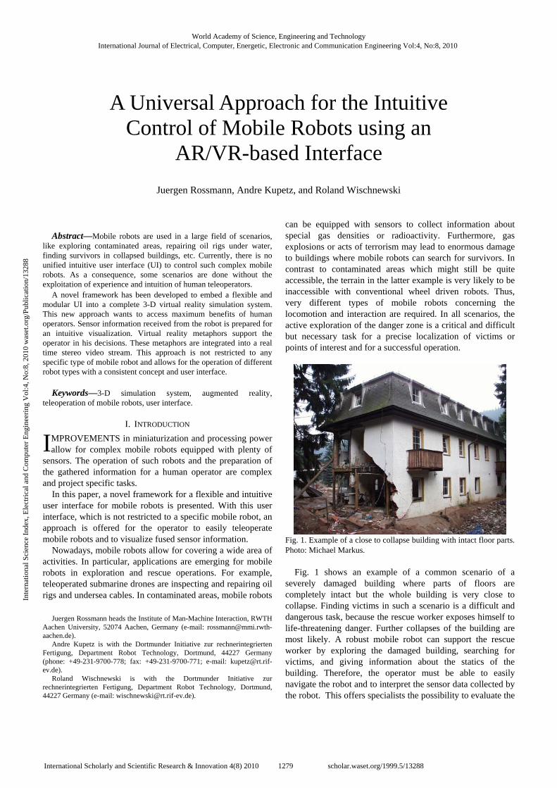
Fig. 1. Example of a close to collapse building with intact floor parts. Photo: Michael Markus.
Fig. 1 shows an example of a common scenario of a severely damaged building where parts of floors are completely intact but the whole building is very close to collapse. Finding victims in such a scenario is a difficult and dangerous task, because the rescue worker exposes himself to life-threatening danger. Further collapses of the building are most likely. A robust mobile robot can support the rescue worker by exploring the damaged building, searching for victims, and giving information about the statics of the building. Therefore, the operator must be able to easily navigate the robot and to interpret the sensor data collected by the robot. This offers specialists the possibility to evaluate the
A Universal Approach for the Intuitive Control of Mobile Robots using an
AR/VR-based Interface Juergen Rossmann, Andre Kupetz, and Roland Wischnewski
I
World Academy of Science, Engineering and TechnologyInternational Journal of Electrical, Computer, Energetic, Electronic and Communication Engineering Vol:4, No:8, 2010
1279International Scholarly and Scientific Research & Innovation 4(8) 2010 scholar.waset.org/1999.5/13288
Inte
rnat
iona
l Sci
ence
Ind
ex, E
lect
rica
l and
Com
pute
r E
ngin
eeri
ng V
ol:4
, No:
8, 2
010
was
et.o
rg/P
ublic
atio
n/13
288
building’s structure. So, the rescue operation can be planned more efficiently and with less danger for the rescue worker.
Even large-area catastrophes like earthquakes can often be broken down into several spots of small operation areas. As a result, the rescue worker will concentrate on one special building and faces a relatively small area of exploration. For a fast and efficient exploration of this area, the use of mobile robots is well suited.
In this field of research, different approaches exist for the design and control of mobile robots. Currently, most approaches try to develop autonomous and map-generating robots. In contrast to this, the authors interests are not autonomous but teleoperated robots. The advantages of continuous teleoperation of mobile robots in many scenarios cannot be fully exploited yet because of inadequate user interfaces. Instead of an autonomous operation mode, the authors want to incorporate the intuition and experience of a human teleoperator, too. In this approach, the robot makes the low-level decisions that would overstrain the operator. For example, the robot is in charge to position its drive assemblies for an optimal traction. Furthermore, the robot calculates values for the different joints to ensure an optimal center of gravity to move along on an incline. However, the operator evaluates and interprets the sensor values. He can decide about points of interest to look at closer. For example, the operator may get evidence for the building’s stability, may have an idea which direction is most promising to search for victims, or he gets information how to activate valves of a wrecked drilling platform to stop leakages. For this purpose, a high-level user interface is offered for the operator. This user interface is not restricted to one special robot platform. Furthermore, it is designed for different interaction media. This novel approach combines experiences in the fields of augmented reality (AR) and virtual reality (VR) the authors gained in [1]–[4] into a framework for a flexible, reusable, and modular user interface.
II. RELATED WORK The tragedy at the World Trade Center in 2001 propelled
search-and-rescue robotics into its next stage and offered an unfortunate opportunity to evaluate human-robot interaction under real conditions. At this time, most rescue robots were operated with the help of remote control box like devices [5].
The RoboCup-Rescue project [6] promotes research and development in this socially significant domain at various levels. This involves multi-agent team work coordination, physical robotic agents for search-and-rescue operations, information infrastructures, personal digital assistants, evaluation benchmarks for rescue strategies, and robotic systems which all will be integrated into a comprehensive system in the future. But currently, this approach is not designed for realistic rough terrain, and the focus lies on an autonomous and not a teleoperated exploration [7]. Researchers, e.g. [8], put lots of effort in solving the “Simultaneous Localization and Mapping Problem” (SLAM).
In consequence, the robots need high intelligence and computation power for their algorithms. Despite the progress in the last years, however, these rescue robots are far away from a successful autonomous exploration in a real scenario. For example, [9] shows the design and development of a robot for rescue missions and outlines the weakness in its mechanical design and path-planning in the conclusion. The necessary communication between operator and robot is done via a remote desktop connection between a notebook integrated into the mobile robot and a notebook at the operating station.
To reduce the required computational power on the robot, the sensor values should be submitted to the teleoperation station, where this information is evaluated and prepared for an intuitive visualization. This concept is in contrast to [9] where all computations are carried out on the robot itself. An IP-based communication is proposed between robot and operating station, which splits the software into two modular parts: one part is running on the robot and the other one on the teleoperation station. Reference [10] describes a multimodal interactive control method called “telecommanding” for teleoperating wheeled mobile robots over the internet in well structured environments. Though this concept is not designed for rough terrain and the robot is equipped with a minimum of sensors only, the paper shows interesting aspects for teleoperation at small bandwidths.
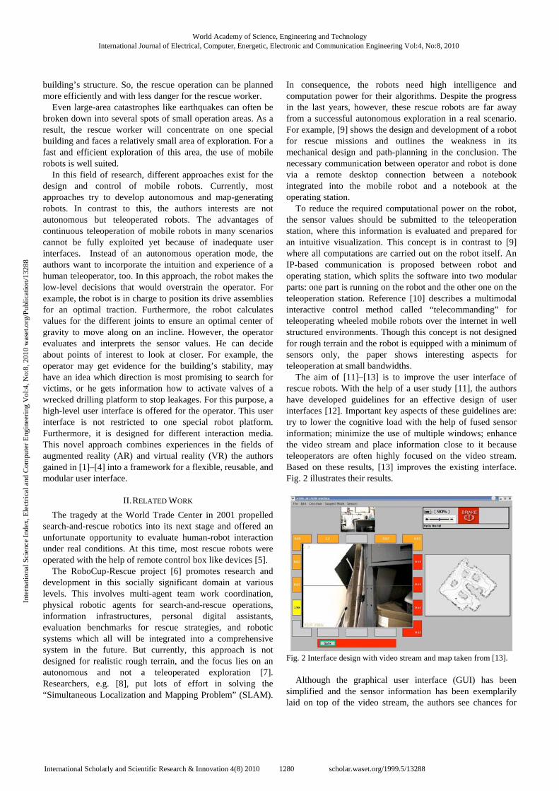
The aim of [11]–[13] is to improve the user interface of rescue robots. With the help of a user study [11], the authors have developed guidelines for an effective design of user interfaces [12]. Important key aspects of these guidelines are: try to lower the cognitive load with the help of fused sensor information; minimize the use of multiple windows; enhance the video stream and place information close to it because teleoperators are often highly focused on the video stream. Based on these results, [13] improves the existing interface. Fig. 2 illustrates their results.
Fig. 2 Interface design with video stream and map taken from [13].
Although the graphical user interface (GUI) has been
simplified and the sensor information has been exemplarily laid on top of the video stream, the authors see chances for
World Academy of Science, Engineering and TechnologyInternational Journal of Electrical, Computer, Energetic, Electronic and Communication Engineering Vol:4, No:8, 2010
1280International Scholarly and Scientific Research & Innovation 4(8) 2010 scholar.waset.org/1999.5/13288
Inte
rnat
iona
l Sci
ence
Ind
ex, E
lect
rica
l and
Com
pute
r E
ngin
eeri
ng V
ol:4
, No:
8, 2
010
was
et.o
rg/P
ublic
atio
n/13
288
improvements with a more flexible and modular approach. Reference [14] suggests an approach for the development
of a robust and relatively inexpensive fire evacuation guide robot system. The robot combined with its control unit shall act as a link between firefighter and victim and provide sensor information to the teleoperator. The robot can be operated with two types of UIs. The first one is a control box type UI, based on a joystick, wheeled buttons, a display, and predefined communication buttons. A second operation approach has been implemented with the help of a touch screen GUI. Due to the fact that the GUI is designed for a hand held device of small size, the possible display resolution for the GUI is limited. The GUI contains the video stream, some buttons, and several bars for sensor values. The evacuation robot uses an embedded operating system which gets its teleoperating commands via the wireless communication protocol Bluetooth. Additionally, dedicated radio frequency interfaces operating at a frequency of 2.4 GHz are used for transmitting video and audio data. Unfortunately, this way of video transmission is not encrypted. The teleoperator has the possibility to switch between four evacuation robots he is currently controlling.
After all, the teleoperator needs to interact with the graphical user interface through a particular input device. Especially for robot platforms with many degrees of freedom like serpentine robots, which can furthermore be used in highly cluttered environments, this is a very sophisticated task. Reference [15] presents an approach using an automobile-like user interface with steering wheel and foot pedals to control a snake-like robot in a mechanical way. This work has been extended in [16] so that arrows occur on the video stream, which guide the operator to a carbon dioxide source. One major disadvantage of this intuitively controllable robot is that there is a necessary mechanical connection between robot and operating station. For the OmniTread serpentine robot [17], a control concept has been developed that is based on a small model of the real robot called “JoySnake” which is physically modified by the operator [18]. These modifications will then be applied to the real robot.
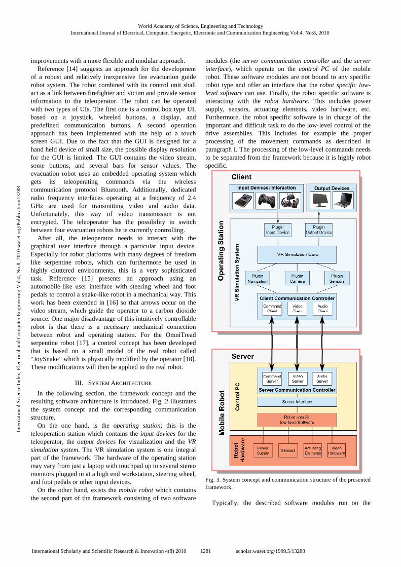
III. SYSTEM ARCHITECTURE In the following section, the framework concept and the
resulting software architecture is introduced. Fig. 2 illustrates the system concept and the corresponding communication structure.
On the one hand, is the operating station; this is the teleoperation station which contains the input devices for the teleoperator, the output devices for visualization and the VR simulation system. The VR simulation system is one integral part of the framework. The hardware of the operating station may vary from just a laptop with touchpad up to several stereo monitors plugged in at a high end workstation, steering wheel, and foot pedals or other input devices.
On the other hand, exists the mobile robot which contains the second part of the framework consisting of two software
modules (the server communication controller and the server interface), which operate on the control PC of the mobile robot. These software modules are not bound to any specific robot type and offer an interface that the robot specific low-level software can use. Finally, the robot specific software is interacting with the robot hardware. This includes power supply, sensors, actuating elements, video hardware, etc. Furthermore, the robot specific software is in charge of the important and difficult task to do the low-level control of the drive assemblies. This includes for example the proper processing of the movement commands as described in paragraph I. The processing of the low-level commands needs to be separated from the framework because it is highly robot specific.
Fig. 3. System concept and communication structure of the presented framework.
Typically, the described software modules run on the
World Academy of Science, Engineering and TechnologyInternational Journal of Electrical, Computer, Energetic, Electronic and Communication Engineering Vol:4, No:8, 2010
1281International Scholarly and Scientific Research & Innovation 4(8) 2010 scholar.waset.org/1999.5/13288
Inte
rnat
iona
l Sci
ence
Ind
ex, E
lect
rica
l and
Com
pute
r E
ngin
eeri
ng V
ol:4
, No:
8, 2
010
was
et.o
rg/P
ublic
atio
n/13
288
control computer of the mobile robot where the robot specific software is running, too. According to this, the framework includes the communication between mobile robot and operating station and offers a defined interface to the robot software. To reduce the required computational power on the robot, the sensor values should be submitted to the teleoperation station, where this information is evaluated and prepared for an intuitive visualization. This concept is in contrast to currently common approaches like [9] where all computations are carried out on the robot itself. An IP-based communication between robot and operating station is proposed. This communication must be fail-safe and robust on the one side. On the other side, the teleoperating interface must be easy to handle by means of the robot specific software. So, a string based IP communication structure is used. This has the advantage that a transparent and well-structured interface is offered for the robot specific software. For a fail-safe operation, it is proposed that each request from the operating station needs to be acknowledged with a solicited message that indicates the status of the request. So, the teleoperator always gets a feedback to his actions.
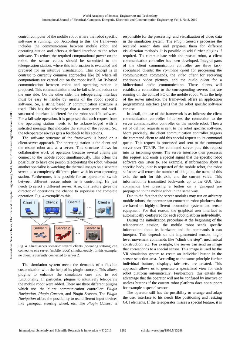
The software structure of the framework is based on a client-server approach. The operating station is the client and the rescue robot acts as a server. This structure allows for collaborative work of operators because several clients can connect to the mobile robot simultaneously. This offers the possibility to have one person teleoperating the robot, whereas another specialist is watching the thermal images on a separate screen at a completely different place with its own operating station. Furthermore, it is possible for an operator to switch between different rescue robots he is controlling. He just needs to select a different server. Also, this feature gives the director of operations the chance to supervise the complete operation. Fig. 4 exemplifies this.
Fig. 4. Client-server scenario: several clients (operating stations) can connect to one server (mobile robot) simultaneously. In this example, no client is currently connected to server 2.
The simulation system meets the demands of a flexible
customization with the help of its plugin concept. This allows plugins to enhance the simulation core and to add functionality. In particular, plugins to intuitively teleoperate the mobile robot were added. There are three different plugins which use the client communication controller: Plugin Navigation, Plugin Camera, and Plugin Sensors. The Plugin Navigation offers the possibility to use different input devices like gamepad, steering wheel, etc. The Plugin Camera is
responsible for the processing and visualization of video data in the simulation system. The Plugin Sensors processes the received sensor data and prepares them for different visualization methods. It is possible to add further plugins if required. To communicate with the rescue robot, a client communication controller has been developed. Integral parts of the client communication controller are three task-specialized clients: the command client for processing the communication commands, the video client for receiving continuous video pictures, and the audio client for a bidirectional audio communication. These clients will establish a connection to the corresponding servers that are running on the control PC of the mobile robot. With the help of the server interface, the framework offers an application programming interface (API) that the robot specific software can use.
In detail, the use of the framework is as follows: the client communication controller initializes the connection to the server communication controller on the mobile robot. Then a set of defined requests is sent to the robot specific software. More precisely, the client communication controller triggers the command client to add this special request to its command queue. This request is processed and sent to the command server over TCP/IP. The command server puts this request into its incoming queue. The server interface then processes this request and emits a special signal that the specific robot software can listen to. For example, if information about a specific body joint is requested of the mobile robot, the robot software will return the number of this joint, the name of this axis, the unit for this axis, and the current value. This information is transmitted backwards up to the GUI. User commands like pressing a button on a gamepad are propagated to the mobile robot in the same way.
Due to the fact that the server modules may run on arbitrary mobile robots, the operator can connect to robot platforms that are based on highly different locomotion systems and sensor equipment. For that reason, the graphical user interface is automatically configured for each robot platform individually.
During the initialization procedure at the beginning of the teleoperation session, the mobile robot sends specific information about its hardware and the commands it can interpret. This depends on the implemented sensors, high-level movement commands like “climb the step”, mechanical construction, etc. For example, the server can send an image that corresponds to a special sensor. This image is used by the VR simulation system to create an individual button in the sensor selection area. According to the same principle further individual buttons, displays, tabs etc. are created. This approach allows us to generate a specialized view for each robot platform automatically. Furthermore, this entails the advantage that the operator will not be confused by inactive or useless buttons if the current robot platform does not support for example a special sensor.
The operator still has the possibility to arrange and adapt the user interface to his needs like positioning and resizing GUI elements. If the teleoperator misses a special feature, it is
World Academy of Science, Engineering and TechnologyInternational Journal of Electrical, Computer, Energetic, Electronic and Communication Engineering Vol:4, No:8, 2010
1282International Scholarly and Scientific Research & Innovation 4(8) 2010 scholar.waset.org/1999.5/13288
Inte
rnat
iona
l Sci
ence
Ind
ex, E
lect
rica
l and
Com
pute
r E
ngin
eeri
ng V
ol:4
, No:
8, 2
010
was
et.o
rg/P
ublic
atio
n/13
288
possible to fulfill the new requirements by creating a new component for this particular need. For example, this may be done by enhancing the sensor plugin with a new custom-built GUI overlay or enhancing the navigation plugin with a new input device like a data glove. As a result, this new feature is available to all visualizations and no changes need to be done to the robot system.
IV. VISUALIZATION CONCEPTS The following chapter describes the integration of the
framework into a simulation system together with concepts for augmented information visualization is presented.
A. Advantages of a VR Simulation System The fact that a complete simulation system is employed,
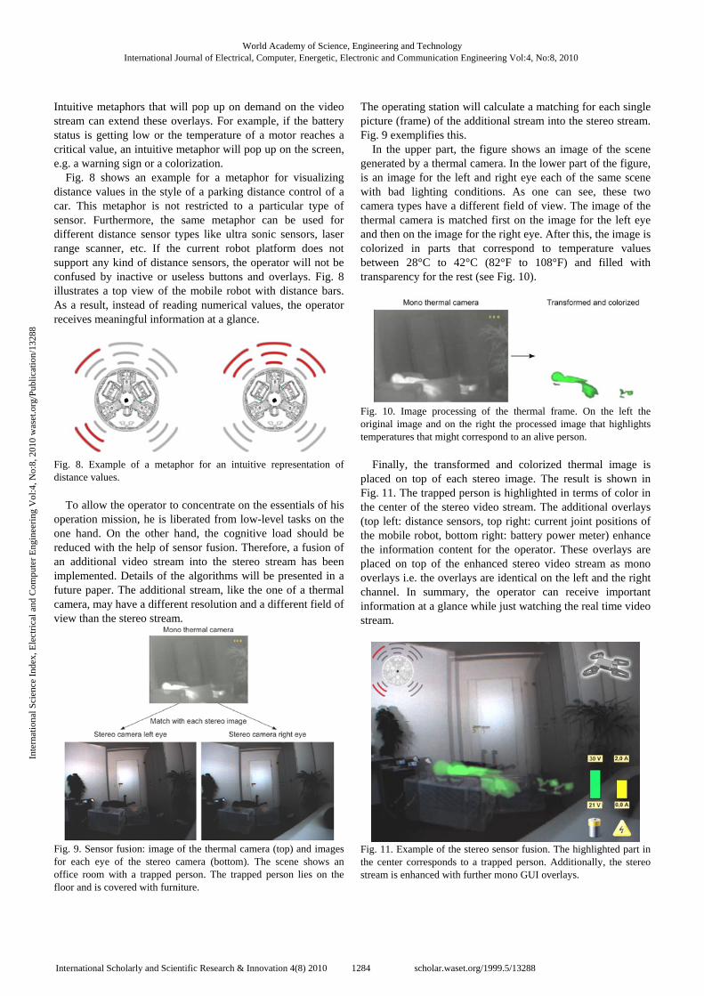
offers the operator a large variety of operating methods that conventional user interfaces cannot provide. For example, the system has a plugin for dynamics simulation, which is of particular use for complex robots with many degrees of freedom. Fig. 5 illustrates a CAD model of a serpentine robot that consists of five modules, which are connected with couplings with three rotational degrees of freedom each. Furthermore, each module (except the last one) has two flippers, which can rotate. The operator modifies positions and orientations of modules in the simulation system and observes the physically correct reaction in the simulation in real time during his interaction with the model. If the operator is pleased with a special position of the model in the simulation he can transfer this setting to the real robot. Additionally, often used settings may be stored in a database and directly accessed on demand.
Fig. 5 A CAD model of a serpentine robot.
One significant feature for the acceptance of a user
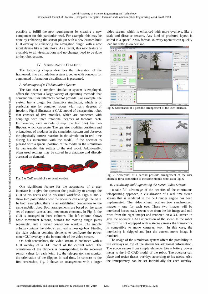
interface is to give the operator the possibility to arrange the GUI to his needs and to his usual workflow. Figs. 6 and 7 show two possibilities how the operator can arrange the GUI. In both examples, there is an established connection to the same mobile robot. Both arrangements are based on the same set of control, sensor, and movement elements. In Fig. 6, the GUI is arranged in three columns. The left column shows basic movement buttons, buttons for moving single joints separately, and a server connection window. The middle column contains the video stream and a message box. Finally, the right column contains elements to configure the power meter GUI overlay in the bottom left of the video stream.
On both screenshots, the video stream is enhanced with a GUI overlay of a 3-D model of the current robot. The orientation of the flippers is corresponding to the received sensor values for each joint. So, the teleoperator can monitor the orientation of the flippers in real time. In contrast to the first screenshot, Fig. 7 shows an arrangement with a larger
video stream, which is enhanced with more overlays, like a scale and distance sensors. Any kind of preferred layout is stored in a special XML format, so every operator can quickly load his settings on demand.
Fig. 6. Screenshot of a possible arrangement of the user interface.
Fig. 7. Screenshot of a second possible arrangement of the user interface for a connection to the same mobile robot as in Fig. 6.
B. Visualizing and Augmenting the Stereo Video Stream To take full advantage of the benefits of the continuous
teleoperating approach, a visualization of a real time stereo stream that is rendered in the 3-D render engine has been implemented. The video client receives two synchronized images – one for each eye. These two images will be interlaced horizontally (even rows from the left image and odd rows from the right image) and rendered on a 3-D screen to give the operator a 3-D impression of the scene. If the robot platform is not equipped with a stereo camera the framework is compatible to mono cameras, too. In this case, the interlacing is skipped and just the current mono image is rendered.
The usage of the simulation system offers the possibility to use overlays on top of the stream for additional information. The scope ranges from simple elements like a battery power meter to the 3-D CAD model of the robot. The operator can place and resize theses overlays according to his needs. Also the transparency can be set individually for each overlay.
World Academy of Science, Engineering and TechnologyInternational Journal of Electrical, Computer, Energetic, Electronic and Communication Engineering Vol:4, No:8, 2010
1283International Scholarly and Scientific Research & Innovation 4(8) 2010 scholar.waset.org/1999.5/13288
Inte
rnat
iona
l Sci
ence
Ind
ex, E
lect
rica
l and
Com
pute
r E
ngin
eeri
ng V
ol:4
, No:
8, 2
010
was
et.o
rg/P
ublic
atio
n/13
288
Intuitive metaphors that will pop up on demand on the video stream can extend these overlays. For example, if the battery status is getting low or the temperature of a motor reaches a critical value, an intuitive metaphor will pop up on the screen, e.g. a warning sign or a colorization.
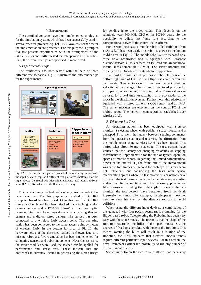
Fig. 8 shows an example for a metaphor for visualizing distance values in the style of a parking distance control of a car. This metaphor is not restricted to a particular type of sensor. Furthermore, the same metaphor can be used for different distance sensor types like ultra sonic sensors, laser range scanner, etc. If the current robot platform does not support any kind of distance sensors, the operator will not be confused by inactive or useless buttons and overlays. Fig. 8 illustrates a top view of the mobile robot with distance bars. As a result, instead of reading numerical values, the operator receives meaningful information at a glance.
Fig. 8. Example of a metaphor for an intuitive representation of distance values.
To allow the operator to concentrate on the essentials of his
operation mission, he is liberated from low-level tasks on the one hand. On the other hand, the cognitive load should be reduced with the help of sensor fusion. Therefore, a fusion of an additional video stream into the stereo stream has been implemented. Details of the algorithms will be presented in a future paper. The additional stream, like the one of a thermal camera, may have a different resolution and a different field of view than the stereo stream.
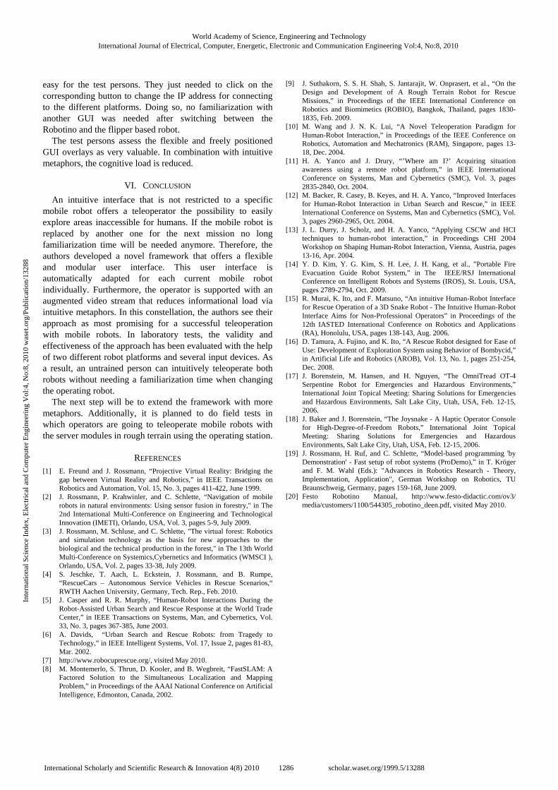
Fig. 9. Sensor fusion: image of the thermal camera (top) and images for each eye of the stereo camera (bottom). The scene shows an office room with a trapped person. The trapped person lies on the floor and is covered with furniture.
The operating station will calculate a matching for each single picture (frame) of the additional stream into the stereo stream. Fig. 9 exemplifies this.
In the upper part, the figure shows an image of the scene generated by a thermal camera. In the lower part of the figure, is an image for the left and right eye each of the same scene with bad lighting conditions. As one can see, these two camera types have a different field of view. The image of the thermal camera is matched first on the image for the left eye and then on the image for the right eye. After this, the image is colorized in parts that correspond to temperature values between 28°C to 42°C (82°F to 108°F) and filled with transparency for the rest (see Fig. 10).
Fig. 10. Image processing of the thermal frame. On the left the original image and on the right the processed image that highlights temperatures that might correspond to an alive person.
Finally, the transformed and colorized thermal image is
placed on top of each stereo image. The result is shown in Fig. 11. The trapped person is highlighted in terms of color in the center of the stereo video stream. The additional overlays (top left: distance sensors, top right: current joint positions of the mobile robot, bottom right: battery power meter) enhance the information content for the operator. These overlays are placed on top of the enhanced stereo video stream as mono overlays i.e. the overlays are identical on the left and the right channel. In summary, the operator can receive important information at a glance while just watching the real time video stream.
Fig. 11. Example of the stereo sensor fusion. The highlighted part in the center corresponds to a trapped person. Additionally, the stereo stream is enhanced with further mono GUI overlays.
World Academy of Science, Engineering and TechnologyInternational Journal of Electrical, Computer, Energetic, Electronic and Communication Engineering Vol:4, No:8, 2010
1284International Scholarly and Scientific Research & Innovation 4(8) 2010 scholar.waset.org/1999.5/13288
Inte
rnat
iona
l Sci
ence
Ind
ex, E
lect
rica
l and
Com
pute
r E
ngin
eeri
ng V
ol:4
, No:
8, 2
010
was
et.o
rg/P
ublic
atio
n/13
288
V. EXPERIMENTS The described concepts have been implemented as plugins
for the simulation system, which has been successfully used in several research projects, e.g. [2], [19]. Now, test scenarios for the implementation are presented. For this purpose, a group of five test persons experimented with the arrangement of the GUI elements and further tested the teleoperation of the robot. First, the different setups are specified in more detail.
A. Experimental Setups The framework has been tested with the help of three
different test scenarios. Fig. 12 illustrates the different setups for the experiments.
Fig. 12. Experimental setups: screenshot of the operating station with the input devices (top) and different test platforms (bottom). Bottom right photo: Lehrstuhl für Maschinenelemente und Konstruktions-lehre (LMK), Ruhr-Universität Bochum, Germany.
First, a stationary testbed without any kind of robot has
been developed. For this purpose, an embedded PC/104+ computer board has been used. Onto this board a PC/104+ frame grabber board has been stacked for attaching analog camera devices and a PC/104+ FireWire board for digital cameras. First tests have been done with an analog thermal camera and a digital stereo camera. The testbed has been connected to a wireless LAN access point. The operating station has been connected to the same access point by means of wireless LAN. In the bottom left area of Fig. 12, the hardware setup of the described testbed is shown. Due to a missing robot, a software emulation has been implemented for simulating sensors and robot movements. Nevertheless, since the server modules were used, the testbed can be applied for performance and stress tests. These indicate that the bottleneck is currently located in processing the stereo image
for sending it to the video client. This depends on the relatively weak 500 MHz CPU on the PC/104 board. So, the possibility to adjust the frame rate according to the computational power of the control PC is offered.
For a second test case, a mobile robot called Robotino from FESTO [20] has been used. This robot is shown in the bottom middle area in Fig. 12. The mobile robot system is based on a three drive omniwheel and is equipped with ultrasonic distance sensors, a USB camera, an I/O card and an additional inertial measurement unit (IMU). The server modules run directly on the Robotino as a stand-alone application.
The third test case is a flipper based robot platform in the bottom right area of Fig. 12. Each flipper is chain driven and can rotate. The motor-control monitors current position, velocity, and amperage. The currently monitored position for a flipper is corresponding to its joint value. These values can be used for a real time visualization of a 3-D model of the robot in the simulation system. Furthermore, this platform is equipped with a stereo camera, a CO2 sensor, and an IMU. The server modules are executed on the control PC of the mobile robot. The network connection is established over wireless LAN.
B. Teleoperation Tests An operating station has been equipped with a stereo
monitor, a steering wheel with pedals, a space mouse, and a gamepad. First, we h the latency between sending commands from the operating station and receiving the affirmation from the mobile robot using wireless LAN has been tested. This period takes about 50 ms in average. The test persons have verified that the latency for changing velocities or stopping movements is unproblematic for the use of typical operation speeds of mobile robots. Regarding the limited computational power of the control PC, the frame rate of the stereo stream was set to five frames per second for each eye. This may seem not sufficient, but considering the tests with typical teleoperating speeds where no fast movements or actions have occurred, the test persons deem the frame rate adequate. After a short familiarization time with the necessary polarization filter glasses and finding the right angle of view to the 3-D monitor, the test persons have benefitted from the depth impression very much. For example, the teleoperator does not need to keep his eyes on the distance sensors to avoid collisions.
When using the different input devices, a combination of the gamepad with foot pedals seems most promising for the flipper based robot. Teleoperating the Robotino has been very easy with the space mouse. The reason is that the shape of the Robotino resembles the billet of the space mouse. So, the degrees of freedoms correlate with those of the Robotino. This means, rotating the billet will result in a rotation of the Robotino, etc. This indicates that different mobile robots require different particular input devices. For this reason, the novel framework offers the possibility to use any number of different input devices.
Switching between the two robot platforms has been very
World Academy of Science, Engineering and TechnologyInternational Journal of Electrical, Computer, Energetic, Electronic and Communication Engineering Vol:4, No:8, 2010
1285International Scholarly and Scientific Research & Innovation 4(8) 2010 scholar.waset.org/1999.5/13288
Inte
rnat
iona
l Sci
ence
Ind
ex, E
lect
rica
l and
Com
pute
r E
ngin
eeri
ng V
ol:4
, No:
8, 2
010
was
et.o
rg/P
ublic
atio
n/13
288
easy for the test persons. They just needed to click on the corresponding button to change the IP address for connecting to the different platforms. Doing so, no familiarization with another GUI was needed after switching between the Robotino and the flipper based robot.
The test persons assess the flexible and freely positioned GUI overlays as very valuable. In combination with intuitive metaphors, the cognitive load is reduced.
VI. CONCLUSION An intuitive interface that is not restricted to a specific
mobile robot offers a teleoperator the possibility to easily explore areas inaccessible for humans. If the mobile robot is replaced by another one for the next mission no long familiarization time will be needed anymore. Therefore, the authors developed a novel framework that offers a flexible and modular user interface. This user interface is automatically adapted for each current mobile robot individually. Furthermore, the operator is supported with an augmented video stream that reduces informational load via intuitive metaphors. In this constellation, the authors see their approach as most promising for a successful teleoperation with mobile robots. In laboratory tests, the validity and effectiveness of the approach has been evaluated with the help of two different robot platforms and several input devices. As a result, an untrained person can intuitively teleoperate both robots without needing a familiarization time when changing the operating robot.
The next step will be to extend the framework with more metaphors. Additionally, it is planned to do field tests in which operators are going to teleoperate mobile robots with the server modules in rough terrain using the operating station.
REFERENCES [1] E. Freund and J. Rossmann, “Projective Virtual Reality: Bridging the
gap between Virtual Reality and Robotics,” in IEEE Transactions on Robotics and Automation, Vol. 15, No. 3, pages 411-422, June 1999.
[2] J. Rossmann, P. Krahwinler, and C. Schlette, “Navigation of mobile robots in natural environments: Using sensor fusion in forestry," in The 2nd International Multi-Conference on Engineering and Technological Innovation (IMETI), Orlando, USA, Vol. 3, pages 5-9, July 2009.
[3] J. Rossmann, M. Schluse, and C. Schlette, "The virtual forest: Robotics and simulation technology as the basis for new approaches to the biological and the technical production in the forest," in The 13th World Multi-Conference on Systemics,Cybernetics and Informatics (WMSCI ), Orlando, USA, Vol. 2, pages 33-38, July 2009.
[4] S. Jeschke, T. Aach, L. Eckstein, J. Rossmann, and B. Rumpe, “RescueCars – Autonomous Service Vehicles in Rescue Scenarios,“ RWTH Aachen University, Germany, Tech. Rep., Feb. 2010.
[5] J. Casper and R. R. Murphy, “Human-Robot Interactions During the Robot-Assisted Urban Search and Rescue Response at the World Trade Center,” in IEEE Transactions on Systems, Man, and Cybernetics, Vol. 33, No. 3, pages 367-385, June 2003.
[6] A. Davids, “Urban Search and Rescue Robots: from Tragedy to Technology,” in IEEE Intelligent Systems, Vol. 17, Issue 2, pages 81-83, Mar. 2002.
[7] http://www.robocuprescue.org/, visited May 2010. [8] M. Montemerlo, S. Thrun, D. Kooler, and B. Wegbreit, “FastSLAM: A
Factored Solution to the Simultaneous Localization and Mapping Problem,” in Proceedings of the AAAI National Conference on Artificial Intelligence, Edmonton, Canada, 2002.
[9] J. Suthakorn, S. S. H. Shah, S. Jantarajit, W. Onprasert, et al., “On the Design and Development of A Rough Terrain Robot for Rescue Missions,” in Proceedings of the IEEE International Conference on Robotics and Biomimetics (ROBIO), Bangkok, Thailand, pages 1830-1835, Feb. 2009.
[10] M. Wang and J. N. K. Lui, “A Novel Teleoperation Paradigm for Human-Robot Interaction,” in Proceedings of the IEEE Conference on Robotics, Automation and Mechatronics (RAM), Singapore, pages 13-18, Dec. 2004.
[11] H. A. Yanco and J. Drury, “’Where am I?’ Acquiring situation awareness using a remote robot platform,” in IEEE International Conference on Systems, Man and Cybernetics (SMC), Vol. 3, pages 2835-2840, Oct. 2004.
[12] M. Backer, R. Casey, B. Keyes, and H. A. Yanco, “Improved Interfaces for Human-Robot Interaction in Urban Search and Rescue,” in IEEE International Conference on Systems, Man and Cybernetics (SMC), Vol. 3, pages 2960-2965, Oct. 2004.
[13] J. L. Durry, J. Scholz, and H. A. Yanco, “Applying CSCW and HCI techniques to human-robot interaction,” in Proceedings CHI 2004 Workshop on Shaping Human-Robot Interaction, Vienna, Austria, pages 13-16, Apr. 2004.
[14] Y. D. Kim, Y. G. Kim, S. H. Lee, J. H. Kang, et al., ”Portable Fire Evacuation Guide Robot System,” in The IEEE/RSJ International Conference on Intelligent Robots and Systems (IROS), St. Louis, USA, pages 2789-2794, Oct. 2009.
[15] R. Murai, K. Ito, and F. Matsuno, “An intuitive Human-Robot Interface for Rescue Operation of a 3D Snake Robot - The Intuitive Human-Robot Interface Aims for Non-Professional Operators” in Proceedings of the 12th IASTED International Conference on Robotics and Applications (RA), Honolulu, USA, pages 138-143, Aug. 2006.
[16] D. Tamura, A. Fujino, and K. Ito, “A Rescue Robot designed for Ease of Use: Development of Exploration System using Behavior of Bombycid,” in Artificial Life and Robotics (AROB), Vol. 13, No. 1, pages 251-254, Dec. 2008.
[17] J. Borenstein, M. Hansen, and H. Nguyen, “The OmniTread OT-4 Serpentine Robot for Emergencies and Hazardous Environments,” International Joint Topical Meeting: Sharing Solutions for Emergencies and Hazardous Environments, Salt Lake City, Utah, USA, Feb. 12-15, 2006.
[18] J. Baker and J. Borenstein, “The Joysnake - A Haptic Operator Console for High-Degree-of-Freedom Robots,” International Joint Topical Meeting: Sharing Solutions for Emergencies and Hazardous Environments, Salt Lake City, Utah, USA, Feb. 12-15, 2006.
[19] J. Rossmann, H. Ruf, and C. Schlette, “Model-based programming 'by Demonstration' - Fast setup of robot systems (ProDemo),” in T. Kröger and F. M. Wahl (Eds.): "Advances in Robotics Research - Theory, Implementation, Application", German Workshop on Robotics, TU Braunschweig, Germany, pages 159-168, June 2009.
[20] Festo Robotino Manual, http://www.festo-didactic.com/ov3/ media/customers/1100/544305_robotino_deen.pdf, visited May 2010.
World Academy of Science, Engineering and TechnologyInternational Journal of Electrical, Computer, Energetic, Electronic and Communication Engineering Vol:4, No:8, 2010
1286International Scholarly and Scientific Research & Innovation 4(8) 2010 scholar.waset.org/1999.5/13288
Inte
rnat
iona
l Sci
ence
Ind
ex, E
lect
rica
l and
Com
pute
r E
ngin
eeri
ng V
ol:4
, No:
8, 2
010
was
et.o
rg/P
ublic
atio
n/13
288