a uml profile for developing airworthiness-compliant … · permettant a la bibliotheque et...
TRANSCRIPT

A UML Profile For Developing Airworthiness-Compliant (RTCA DO-178B)
Safety-Critical SoftwareBy
Gregory Zoughbi
A thesis submitted to
The Faculty of Graduate Studies and Research
In partial fulfillment of the requirements of the degree of
Master’s of Applied Science
Ottawa-Carleton Institute of Electrical and Computer Engineering
Department of Systems and Computer Engineering
Carleton University
Ottawa, Ontario, K1S 5B6
Canada
December 2006
Copyright © 2006 by Gregory Zoughbi
Reproduced with permission of the copyright owner. Further reproduction prohibited without permission.

Library and Archives Canada
Bibliotheque et Archives Canada
Published Heritage Branch
395 Wellington Street Ottawa ON K1A 0N4 Canada
Your file Votre reference ISBN: 978-0-494-23353-5 Our file Notre reference ISBN: 978-0-494-23353-5
Direction du Patrimoine de I'edition
395, rue Wellington Ottawa ON K1A 0N4 Canada
NOTICE:The author has granted a nonexclusive license allowing Library and Archives Canada to reproduce, publish, archive, preserve, conserve, communicate to the public by telecommunication or on the Internet, loan, distribute and sell theses worldwide, for commercial or noncommercial purposes, in microform, paper, electronic and/or any other formats.
AVIS:L'auteur a accorde une licence non exclusive permettant a la Bibliotheque et Archives Canada de reproduire, publier, archiver, sauvegarder, conserver, transmettre au public par telecommunication ou par I'lnternet, preter, distribuer et vendre des theses partout dans le monde, a des fins commerciales ou autres, sur support microforme, papier, electronique et/ou autres formats.
The author retains copyright ownership and moral rights in this thesis. Neither the thesis nor substantial extracts from it may be printed or otherwise reproduced without the author's permission.
L'auteur conserve la propriete du droit d'auteur et des droits moraux qui protege cette these.Ni la these ni des extraits substantiels de celle-ci ne doivent etre imprimes ou autrement reproduits sans son autorisation.
In compliance with the Canadian Privacy Act some supporting forms may have been removed from this thesis.
While these forms may be included in the document page count, their removal does not represent any loss of content from the thesis.
Conformement a la loi canadienne sur la protection de la vie privee, quelques formulaires secondaires ont ete enleves de cette these.
Bien que ces formulaires aient inclus dans la pagination, il n'y aura aucun contenu manquant.
i * i
CanadaReproduced with permission of the copyright owner. Further reproduction prohibited without permission.

iii
ABSTRACT
Many safety-related and certification standards exist for developing safety-critical
systems. Safety assessments are performed in practice, and system certification according
to a standard requires the submitting information about the software. The airworthiness
standard, RTCA DO-178B, is the software de-facto standard for commercial and military
aerospace programmes. The objective of this research is to propose an approach to
improve the line of communication between safety engineers and software engineers by
proposing a Unified Modeling Language (UML) profile that allows software engineers to
model safety related concepts and properties in UML, the de-facto software modeling
language. In this research, the list of safety-related concepts is extracted from RTCA DO-
178B, and then a UML profile is presented to enable modeling them. Then, approaches to
generate certification-related information from UML models are presented. This new
approach is illustrated through a case study on developing an aircraft’s navigation
controller subsystem.
Keywords: UML, UML Profile, Airworthiness, RTCA DO-178B, Safety, Safety-
Critical, Safety Assessment, Certification, Certification Authority.
Reproduced with permission of the copyright owner. Further reproduction prohibited without permission.

ACKNOWLEDGEMENTS
I would like to express sincere gratitude for all those who have helped me throughout this
thesis. First and foremost, I would like to thank my parents Hiyam and Saleem, and my
brother Michael, for continuously and unconditionally supporting me throughout my life.
They have always encouraged me to pursue career-defining opportunities, and the
successful completion of this thesis is no different. I would not have been able to
complete this work without them.
I would like to thank my thesis supervisors, Dr. Lionel Briand and Dr. Yvan Labiche.
They have guided me throughout my master’s degree by helping me select appropriate
courses, developing my interest in safety-critical systems, and most importantly working
closely with me to significantly increase the quality of this thesis. Their constructive
feedback and input was instrumental for this research.
In addition, I would like to thank Dr. Fred Cotaras of General Dynamics (GD) Canada for
helping me define the research problem and relate it to practical needs of engineering
organizations. Fred helped me take the first, and most challenging, step of this journey.
Last but not least, I would like to thank Mr. Christopher Sean Elliott, my software
engineering mentor at the Aurora Data Management System (DMS) project at GD
Canada, for coaching me on how to design high-quality software for large and complex
software systems. Chris has provided me with effective software engineering skills,
which he acquired through decades of experience developing large software systems such
Reproduced with permission of the copyright owner. Further reproduction prohibited without permission.

as the Canadian Automated Air Traffic System (CAATS) - a software system which,
according to Chris, has “one of the finest architectures ever devised”. Those skills were
vital in the design of the UML profile in this thesis.
Thank you all!
Gregory Zoughbi
December 2006
Ottawa, Canada
Reproduced with permission of the copyright owner. Further reproduction prohibited without permission.

TABLE OF CONTENTS
1 INTRODUCTION.............................................................................................................. 11.1 S a f e t y a n d U M L ................................................................................................................................. 1
1 .2 R e s e a r c h P r o b l e m ........................................................................................................................... 4
1.3 D o c u m e n t O r g a n iz a t io n .............................................................................................................5
1.4 R e s e a r c h M e t h o d .............................................................................................................................9
2 INDUSTRIAL PRESPECTIVE.................................................................................... 122.1 S a f e t y A s s e s s m e n t s .......................................................................................................................12
2 .2 S a f e t y -R e l a t e d S t a n d a r d s ..................................................................................................... 14
2 .3 C h a l l e n g e s in S o f t w a r e S a f e t y ...........................................................................................17
2 .4 U s a g e S c e n a r io s f o r S a f e t y In f o r m a t io n .................................................................... 18
2 .5 T r a c e a b il it y R e q u ir e m e n t s ....................................................................................................2 2
2 .6 U M L A P P R O A C H ............................................................................................................................232.6.1 Disadvantages......................................................................................................... 242.6.2 Advantages.............................................................................................................. 252.6.3 Requirements of an Effective UML Profile..............................................................28
3 SAFETY-RELATED CONCEPTS...............................................................................313.1 C o n c e p t Id e n t if ic a t io n a n d C a t e g o r iz a t io n ..............................................................3 4
3 .2 C o n c e p t R e f in e m e n t ..................................................................................................................... 413.2.1 Conceptual Model....................................................................................................433.2.2 Concept Details........................................................................................................443.2.3 Concepts Specifications...........................................................................................473.2.4 Providing Traceability.............................................................................................73
3 .3 In f o r m a t io n R e q u ir e m e n t s ..................................................................................................... 7 4
4 EXISTING UML PROFILES.........................................................................................824 .1 Q u a l it y o f S er v ic e a n d Fa u l t T o l e r a n c e O M G Pr o ftt f. .....................................82
4 .2 SCHEDULABILITY, PERFORMANCE, AND TIME O M G PROFILE........................................83
4 .3 H ID O O R S Pr o f il e ............................................................................................................................ 8 4
4 .4 E ffec ts o f M e s s a g e L o s s , D e l a y , a n d C o r r u p t io n .................................................. 85
4 .5 Pa t t e r n s f o r R e l ia b il it y a n d S a f e t y ............................................................................... 8 6
4 .6 S u m m a r y ................................................................................................................................................ 86
5 PROPOSED UML PROFILE......................................................................................... 895.1 U M L P r o file— Te m p l a t e D e sc r ip t io n ............................................................................... 89
5 .2 Pr o file D e s c r ip t io n ....................................................................................................................... 935.2.1 < <SafetyContext> >................................................................................................. 935.2.2 «ReliabilityC ontext» .......................................................................................... 945.2.3 «In tegrityC ontext» ............................................................................................. 94
Reproduced with permission of the copyright owner. Further reproduction prohibited without permission.

v i i
5.2.4 < <PerformanceContext> >....................................................................................... 955.2.5 «ConcurrencyContext» ..................................................................................... 965.2.6 «CertificationC ontext» ..................................................................................... 965.2.7 < <DesignContext> > ................................................................................................ 975.2.8 « ConfigurationContext> >....................................................................................975.2.9 < <Requirement> >.................................................................................................... 985.2.10 < <Deviation » ....................................................................................................995.2.11 «Im plem entationStyle» .................................................................................1005.2.12 «B ehaviouralS tyle» ......................................................................................1015.2.13 « N a t u r e » ......................................................................................................1025.2.14 « R a t io n a le » .................................................................................................. 1035.2.15 « E v e n t » ........................................................................................................1045.2.16 « R e a c t io n » ................................................................................................... 1055.2.17 « S a fe tyC r itica l» ........................................................................................... 1065.2.18 « P a r t i t io n » ................................................................................................... 1075.2.19 « H a n d le r » .................................................................................................... 1085.2.20 « M o n i t o r » .................................................................................................... 1095.2.21 « S im u la to r » .................................................................................................. 1105.2.22 < <Strategy> > .................................................................................................... I l l5.2.23 « F o r m a lis m » ................................................................................................ 1125.2.24 « C o m p le x ity » ............................................................................................... 1135.2.25 « I n te r fa c e » ................................................................................................... 1145.2.26 « C o n c u r re n t» ............................................................................................... 1155.2.27 « D e fe n s iv e » .................................................................................................. 1165.2.28 « C o n flg u ra b le» ............................................................................................ 1175.2.29 < <Loadable» .................................................................................................. 1185.2.30 « C o n fig u ra to r» ............................................................................................. 1195.2.31 « R e p lic a te d » ..................................................................................................1205.2.32 « C o m p a ra to r» .............................................................................................. 121
5 .3 E x a m p l e s ......................................................................................................................................... 1225.3.1 Hardware/Software Interfaces...............................................................................1225.3.2 Contributions to Failure Conditions...................................................................... 1245.3.3 Software Configurations........................................................................................ 128
5 .4 D e v e l o p m e n t M e t h o d o l o g y ............................................................................................129
6 GENERATION OF CERTIFICATION INFORMATION.................................1336.1 T e c h n o l o g ic a l R e q u ir e m e n t s ..........................................................................................133
6.1.1 Integrated Support in UML Modeling Tools.......................................................... 1346.1.2 Exporting UML Models using XMI........................................................................ 135
6 .2 E x a m p l e s ......................................................................................................................................... 1366.2.1 Hardware/Software Interfaces............................................................................... 1376.2.2 Contributions to Failure Conditions...................................................................... 1386.2.3 COTS Software....................................................................................................... 1396.2.4 Software Partitioning.............................................................................................1396.2.5 Requirements and Traceability.............................................................................. 1406.2.6 Multiple-Version Dissimilar Software................................................................... 1426.2.7 Recursive Software................................................................................................. 143
7 CASE STUDY - NAVIGATION CONTROLLER............................................... 145
Reproduced with permission of the copyright owner. Further reproduction prohibited without permission.
v i i i
7.1 O v e r v ie w ........................................................................................................................................... 146
7 .2 S y st e m A r c h it e c t u r e .............................................................................................................. 148
7 .3 Fu n c t io n a l R e q u ir e m e n t s .................................................................................................... 152
7 .4 S a f e t y A s s e s s m e n t .....................................................................................................................1537.4.1 Action Error Analysis (AEA).................................................................................. 1547.4.2 Failure Modes and Effects Analysis (FMEA)....................................................... 1557.4.3 Hazards and Operability Analysis (HAZOP)........................................................1567.4.4 Interface Analyses (IA).......................................................................................... 1567.4.5 Safety Requirements.............................................................................................. 157
7 .5 S u b s y s t e m D e s i g n ...................................................................................................................... 1597.5.1 Identification of Events and Reactions.................................................................. 1607.5.2 Events.................................................................................................................... 1617.5.3 Reactions............................................................................................................... 1667.5.4 Event-Reaction Relationships............................................................................... 1727.5.5 High-Level Design................................................................................................ 1757.5.6 Low-Level Design of Events and Reactions.......................................................... 194
7 .6 D e sig n A n a l y s i s ............................................................................................................................1967.6.1 USAGE 1: Provide Safety Requirements...............................................................1967.6.2 USAGE 2: Design Safety Requirements in Systems...............................................1977.6.3 USAGE 3: Justify Design Decisions...................................................................... 1997.6.4 USAGE 4: Monitor Safety......................................................................................2007.6.5 USAGE 5: Get Safety Information.........................................................................203
8 CONCLUSION.............................................................................................................. 2068.1 F u l f illin g R e q u ir e m e n t s ...................................................................................................... 2 0 8
8 .2 O pe n Is s u e s a n d F u t u r e W o r k ............................................................................................. 2 1 0
9 SUMMARY.....................................................................................................................215
REFERENCES........................................................................................................................218
APPENDIX A EXAMPLES OF SAFETY/RISK ASSESSMENT METHODS 223
APPENDIX B EXAMPLES OF SAFETY-RELATED STANDARDS...............226
APPENDIX C CONCEPT IDENTIFICATION AND CATEGORIZATION FROM THE AIRWORTHINESS STANDARD............................................................. 229
C . 1 P r im a r il y S a f e t y C o n c e p t s ..................................................................................................2 2 9
C .2 Pr im a r il y R e l ia b il it y C o n c e p t s ....................................................................................... 2 3 2
C .3 Pr im a r il y In t e g r it y C o n c e p t s ........................................................................................... 2 3 4
C .4 Pr im a r il y Pe r f o r m a n c e C o n c e p t s ..................................................................................235
C .5 Pr im a r il y C o n c u r r e n c y C o n c e p t s ..................................................................................2 3 5
C .6 P r im a r il y C e r t if ic a t io n C o n c e p t s ..................................................................................2 3 7
C .7 P r im a r il y D e sig n C o n c e p t s ..................................................................................................2 3 8
C .8 Pr im a r il y C o n f ig u r a t io n C o n c e p t s ................................................................................2 4 2
Reproduced with permission of the copyright owner. Further reproduction prohibited without permission.

APPENDIX D CONCEPTUAL MODEL— CONCEPT RELATIONSHIPS... 244
APPENDIX E GOM AA’S CLASS CLASSIFICATION....................................... 250
APPENDIX F ASSESSING EXISTING PROFILES BASED ON THE INFORMATION REQUIREMENTS................................................................................251
F. 1 Q u a l it y o f S e r v ic e a n d F a u l t T o l e r a n c e O M G Pr o file (d is c u s s e d in
Se c t io n 4 .1 ) ......................................................................................................................................................251
F.2 SCHEDULABILITY, PERFORMANCE, AND TIME OMG PROFILE (DISCUSSED INSe c t io n 4.2)...........................................................................................................................253F.3 HIDOORS P r o f il e (d is c u s s e d in S e c t io n 4 .3 )................................................255F.4 E ffe c t s o f M e s s a g e L o s s , D e l a y , a n d C o r r u p t io n (d is c u s s e d in S e c t io n
4.4) 257F.5 P a t t e r n s f o r R e l ia b il it y a n d S a f e t y (d is c u s s e d in S e c t io n 4.5)............ 259F.6 A s s e s s in g E x is t in g Pr o fil e s b a s e d o n t h e S a f e t y In f o r m a t io n
R e q u ir e m e n t s— S u m m a r y (d is c u s s e d in se c t io n 4.6)..............................................261
APPENDIX G ADDITIONAL UML PROFILE EXAMPLES............................ 263G. 1 COTS S o f t w a r e ............................................................................................................................263G.2 S o f t w a r e P a r t it io n in g ...........................................................................................................265G.3 R e q u ir e m e n t s a n d Tr a c e a b il it y .......................................................................268G .4 M u l t ip l e -V e r s io n D is s im il a r S o f t w a r e ..................................................................... 271
G.5 C o n c u r r e n t S o f t w a r e ............................................................................................................273G.6 S o f t w a r e M o n it o r in g ............................................................................................................. 274
Reproduced with permission of the copyright owner. Further reproduction prohibited without permission.

X
LIST OF TABLEST a b l e 1: D e t a il s o f t h e r e se a r c h m e t h o d s t e p s ............................................................................11Ta b l e 2: E x a m p l e s o f s a f e t y r e q u ir e m e n t s a n d t h e a c c id e n t s t h e y p r o t e c t
AGAINST.......................................................................................................................................................... 13Ta b l e 3: Tr a c in g in f o r m a t io n r e q u ir e m e n t s t o t h e o r ig in a l h ig h -l e v e l
REQUIREMENTS.............................................................................................................................................. 81T a b l e 4: D e t a il s o f t h e d e v e l o p m e n t m e t h o d o l o g y s t e p s ................................................. 1 32T a b l e 5: R e l a t io n sh ip s b e t w e e n e v e n t s a n d r e a c t io n s ........................................................ 1 74T a b l e 6: U sin g t h e pr o p o se d U M L pr o fil e t o fu l fil l t h e in f o r m a t io n
REQUIREMENTS........................................................................................................................................... 2 1 0Ta b l e 7: E x a m p l e s o f sa f e t y o r r is k a s s e s s m e n t m e t h o d s .................................................2 2 5T a b l e 8: S o m e o f t h e m a n y s a f e t y -r e l a t e d s t a n d a r d s t h a t e x is t f o r s e v e r a l
INDUSTRIES................................................................................................................................................... 2 2 8Ta b l e 9: S a f e t y -r e l a t e d c o n c e p t s t h a t a r e c l a s s if ie d a s “p r im a r il y s a f e t y ” . 231T a b l e 10: S a f e t y -r e l a t e d CONCEPTS THAT ARE CLASSIFIED AS “PRIMARILY
r e l ia b il it y ” .............................. ..............234Ta b l e 11: S a f e t y -r e l a t e d c o n c e p t s t h a t a r e c l a s s if ie d a s “p r im a r il y in t e g r it y ” .
.............. 234T a b l e 12: S a f e t y -r e l a t e d CONCEPTS THAT ARE CLASSIFIED AS “PRIMARILY
p e r f o r m a n c e ” ......................... .............. 235T a b l e 13: Sa f e t y -r e l a t e d CONCEPTS THAT ARE CLASSIFIED AS “PRIMARILY
CONCURRENCY” ........................ .............. 236Ta b l e 14: S a f e t y -r e l a t e d CONCEPTS THAT ARE CLASSIFIED AS “PRIMARILY
c e r t if ic a t io n ” ........................ .............. 238T a b l e 15: S a f e t y -r e l a t e d c o n c e p t s t h a t a r e c l a s s if ie d a s “p r im a r il y d e s ig n ” .242T a b l e 16: S a f e t y -r e l a t e d CONCEPTS THAT ARE CLASSIFIED AS “PRIMARILY
c o n f ig u r a t io n ” ..................... .............. 243T a b l e 17: A n a l y s is o f c o n c e p t u a l m o d e l c o n c e p t r e l a t io n s h ip s .................................249T a b l e 18: A ss e s s in g t h e Qu a l it y o f S e r v ic e a n d F a u l t T o l e r a n c e OMG pr o ftle
b a s e d o n t h e in f o r m a t io n r e q u ir e m e n t s ..............................................................................252T a b l e 19: A s s e s s in g t h e S c h e d u l a b il it y , Pe r f o r m a n c e , a n d T im e OMG pr o fil e
BASED ON THE INFORMATION REQUIREMENTS..............................................................................254T a b l e 20: A ss e s s in g th e HIDOORS pr o f il e b a s e d o n t h e in f o r m a t io n
REQUIREMENTS........................................................................................................................................... 256Ta b l e 21: A s s e s s in g t h e E ffe c t s o f M e s s a g e s pr o fil e b a s e d o n t h e in f o r m a t io n
REQUIREMENTS........................................................................................................................................... 258T a b l e 22: A s s e s s in g p a t t e r n s fo r R e l ia b il it y a n d S a f e t y b a s e d o n t h e
INFORMATION REQUIREMENTS............................................................................................................. 260T a b le 23: A s s e s s m e n t s u m m a r y o f e x i s t i n g UML p r o f i l e s b a s e d o n t h e
INFORMATION REQUIREMENTS............................................................................................................. 262
Reproduced with permission of the copyright owner. Further reproduction prohibited without permission.

LIST OF ILLUSTRATIONS (FIGURES)F ig u r e 1: R e s e a r c h m e t h o d ..........................................................................................................................10F ig u r e 2: U sa g e sc e n a r io s fo r s a f e t y in f o r m a t io n ....................................................................19F ig u r e 3: A U M L m o d e l se r v e s a s a c e n t r a l r o l e f o r s t a k e h o l d e r s ............................2 2F ig u r e 4: R o le o f a U M L s a f e t y p r o f il e in th e d e v e l o p m e n t p r o c e s s ...........................2 4F ig u r e 5: R e l a t io n s h ip b e t w e e n s a f e t y a n d o t h e r s a f e t y -r e l a t e d q u a l it y
c a t e g o r ie s a s s u m in g t h a t t h o s e c a t e g o r ie s f o r m m u t u a l l y e x c l u s iv e s e t s ................................................................................................................................................................................39
F ig u r e 6: R e l a t io n sh ip a c r o s s s a f e t y e n t it ie s , a t t r ib u t e s , a n d m e t h o d s ................. 41F ig u r e 7: M e t a -m o d e l f o r t h e r e f in e d s a f e t y -r e l a t e d c o n c e p t s ................................... 4 5F ig u r e 8: K a l m a n fil t e r p r o c e s s in g in p u t , t h r o u g h a n in t e r f a c e , f r o m a
sim u l a t o r (st r u c t u r e ) .......................................................................................................................124F ig u r e 9: L a n d in g w h e e l c o n t r o l l e r p r o c e ssin g u s e r a n d r a d a r in p u t s
(s t r u c t u r e ) ................................................................................................................................................ 127F ig u r e 10: U se r in t e r f a c e l a n g u a g e c o n f ig u r a t io n s (st r u c t u r e ) ...............................129F ig u r e 11: D e v e l o p m e n t m e t h o d o l o g y o f a ir w o r t h in e s s -c o m p l ia n t s o f t w a r e
p r o d u c t s ...................................................................................................................................................... 130F ig u r e 12: S y s t e m a r c h it e c t u r e (s t r u c t u r e ) ...............................................................................149F ig u r e 13: N a v ig a t io n C o n t r o l l e r S u b s y s t e m ’s e v e n t s (s t r u c t u r e ) .......................... 162F ig u r e 14: N a v ig a t io n C o n t r o l l e r s u b s y s t e m r e a c t io n s (s t r u c t u r e ) .......................167F ig u r e 15: N a v ig a t io n C o n t r o l l e r s u b s y s t e m ’s h ig h -l e v e l d e s ig n (st r u c t u r e ).
............................................................................................................................................................................ 176F ig u r e 16: G o m a a ’s c l a s s if ic a t io n o f a p p l ic a t io n c l a s s e s u s in g s t e r e o t y p e s [7].
............................................................................................................................................................................2 5 0F ig u r e 17: A ir c r a f t ’s n a v ig a t io n c o n t r o l l e r u s in g C O T S so f t w a r e (s t r u c t u r e ).
............................................................................................................................................................................2 6 4F ig u r e 18: A ir c r a ft st e e r in g c o n t r o l l e r (st r u c t u r e ) .........................................................2 6 8F ig u r e 19: S a f e t y -r e q u ir e m e n t s f o r a n a ir c r a f t st e e r in g s y s t e m (s t r u c t u r e ) .2 7 0F ig u r e 20: M u l t ip l e -v e r s io n r a d a r fil t e r sy st e m (s t r u c t u r e ) ...................................... 2 7 2F ig u r e 21: C o n c u r r e n t a c c e s s to a n a ir c r a f t ’s C O T S so f t w a r e (s t r u c t u r e ). . 2 7 4 F ig u r e 22: M o n it o r in g t h e a ir c r a f t ’s e n g in e ’s t e m p e r a t u r e (s t r u c t u r e ) 2 7 6
Reproduced with permission of the copyright owner. Further reproduction prohibited without permission.
LIST OF ACRONYMS AND ABBREVIATIONS
AEA Action Error Analysis
AECL Atomic Energy Canada, Limited
AIAA American Institute of Aeronautics and Astronautics
ARINC Aeronautical Radio, Incorporated
CCA Cause-Consequence Analysis
CENELEC European Committee for Electrotechnical Standardisation
CORBA Common Object Resource Broker Architecture
COTS Commercial-Off-The-Shelf
DoD United States Department of Defense
EBNF Extended Backus-Naur Form
EMF Eclipse Modeling Framework
ESA European Space Agency
ETA Event Tree Analysis
FAA Federal Aviation Administration
FHA Fault Hazard Analysis
FIFO First-In-First-Out
FMEA Failure Modes and Effects Analysis
FMECA Failure Modes, Effects, and Criticality Analysis
FT Fault-Tolerant / Fault Tolerance
FT A Fault Tree Analysis
FTP Fly-To-Point
GPS Global Positioning System
HAZOP Hazards and Operability Analysis
HIDOORS High Integrity Distributed Object-Oriented Real-Time Systems
IA Interface Analyses
IEC International Electrotechnical Commission
IEE Institution of Electrical Engineers
IEEE Institute of Electrical & Electronic Engineers
ISO International Organization for Standardization
LAT/LONG Latitude and Longitude
LED Light-Emitting Diode
Reproduced with permission of the copyright owner. Further reproduction prohibited without permission.
LIFO Last-In-First-Out
LLF Linear Logical Framework
MDA Model-Driven Architecture
MISRA Motor Industry Software Reliability Association
MoD United Kingdom Ministry of Defence
MORT Management Oversight and Risk Tree Analysis
MVC Model-View-Controller
NASA National Aeronautics and Space Administration
NATO North Atlantic Treaty Organization
OCL Object Constraint Language
OMG Object Management Group
ORB Object Resource Broker
PSAC Plan for Software Aspects of Certification
QoS Quality of Service
RF Radio Frequency
RMA Rate Monotonic Analysis
RTCA Radio Technical Commission for Aeronautics
SAE Society of Automotive Engineers
SIL Safety Integrity Level
SMHA State Machine Hazard Analysis
SPT Schedulability, Performance, and Time
SQL Structured Query Language
SSAC Streamlining Software Aspects of Certification
SWOT Strengths, Weaknesses, Opportunities, and Threats
VBA Visual Basic for Applications
XMI XML Metadata Interchange
XML Extensible Markup Language
XSL Extensible Stylesheet Language
Reproduced with permission of the copyright owner. Further reproduction prohibited without permission.
1
1 INTRODUCTION
1.1 Safety and UML
Software’s role in various systems has been rapidly increasing over past several decades.
Its purpose is no longer restricted to managing financial or mathematical data. Due to the
technological advances of computer processors, memory and other components, discrete
hardware components in many systems have been replaced by software. Putting software
on aircrafts, for example, has become significantly more affordable than it used to be. As
a result, software now directly affects human life by managing flights, airplanes, ships,
nuclear reactors, medical systems, and many others. This led to increased emphasis on
the quality of software used in such systems. This emphasis focused on many aspects.
First, it led to improved software verification and testing methods to detect software bugs
before the software is delivered and deployed in its target system. However, it was
accepted that software can never be 100% correct and error free. Therefore, fault
tolerance emerged as a design technique to increase the reliability of the software. The
principles of fault tolerance focus on adding protection mechanisms to detect software
failures within a specified software boundary such that the software is able to recover and
continue execution despite the presence of software faults or bugs. Therefore, fault
tolerance aims at reducing the likelihood that the software becomes unavailable due to
software bugs.
However, it was observed that highly reliable software is not necessarily safe within the
context of the system in which it is used. Software is safe if it does not contribute to
Reproduced with permission of the copyright owner. Further reproduction prohibited without permission.
hazards within the context of the system in which it is used, and a system is safe if it does
not cause accidents to or harm its environment. In particular, software may be reliable but
unsafe when any of the following conditions occurs [1]:
1. The software correctly implements the requirements, but the specified behaviour
is unsafe for the system as a whole (i.e. some requirements are unsafe).
2. Some safety-related requirements are missing (i.e. requirements are incomplete).
3. The software implements unintended and unsafe behaviour that is not specified in
the requirements.
As a result, emphasis increased on developing safety requirements, whose goal is to
ensure the safety of the environment in which the system is used. Safety requirements
and constraints are generally the output of safety assessments that are performed on the
system in which the software will be used. As a result, proper requirements development
is vital towards ensuring safety.
Furthermore, safety-related standards generally require gathering information about the
software that is not necessarily related to the implementation of safety-related
requirements. Examples of such information include the use of COTS software and time-
related functions such as filters.
UML is the de-facto standard language for specifying, modeling, analyzing, and
documenting software [2], It is also used in other areas such as modeling systems,
hardware, and even business contexts. UML represents a collection of best engineering
techniques and practices that have proven successful in modeling large and complex
Reproduced with permission of the copyright owner. Further reproduction prohibited without permission.

3
software systems. It is a very important part of the software development process, and is
particularly well-suited for developing object-oriented software. It uses mostly graphical
notations to express the design of software systems. The benefits of UML include helping
project teams communicate, explore potential designs, and validate the software
architecture. It also increases the formalism of the software model, which makes the
analysis process easier. Furthermore, it is the heart of the Model-Driven Architecture
(MDA) initiative [3], whose supporters claim that it is the future of developing software.
UML is an extensible modeling language; it allows developers to add semantics to the
UML language that are applicable in a particular domain, area, or industry. Such added
semantics are called a “UML Profile”, which in effect tailor the UML language to a
specific area of interest such as, for example, fault tolerance, distributed computing, and
Common Object Resource Broker Architecture (CORBA). A UML profile extends the
core UML language by defining additional modeling mechanisms of the following types:
1. Stereotypes: A stereotype is used to describe a UML element in a platform or
domain specific language.
2. Constraints: A constraint is a condition or a restriction that is applied to a UML
element. It can be expressed in any language, regardless on whether it is machine-
readable or not.
3. Tagged Value: A tagged value is used to further describe a stereotyped-element
through parameterization of the stereotype in a platform or domain specific
language.
Reproduced with permission of the copyright owner. Further reproduction prohibited without permission.

4
1.2 Research Problem
Safety assessments are performed on the system as a whole regardless of which of its
features will be implemented in software. As a result, safety requirements are first
developed for the system itself. Once it is determined which functionality will be
implemented in software, the safety requirements associated with that functionality are
allocated to the software that implements it.
Moreover, software certification authorities require information about the software that is
not necessarily captured within the safety requirements. Such information could include
the use of COTS software, time-related functions as filters, state machines, and others.
The certification authorities consider this information along with the safety requirements
when determining whether the software is safe or not.
Generally, safety engineers that perform the safety assessments and collect certification
information are not the software engineers that design and implement the software. In
fact, it is uncommon to find software engineers that are experienced with the safety and
certification aspects of systems and software. Conversely, safety engineers are often
inexperienced with software engineering’s development techniques, including UML. This
creates a critical gap that must be bridged - safety engineers need to have better insight
into the software and to what extent it is compliant with the safety and certification
requirements, and software engineers need to have better understanding of the safety and
certification requirements so that they develop safe software that can run in a certified
system.
Reproduced with permission of the copyright owner. Further reproduction prohibited without permission.

In this research, the airworthiness standard [4], which is the de-facto safety-related
standard in the aerospace industry, is analyzed to extract a list of safety-related concepts
that are of interest to both safety engineers and software engineers. It is argued that if
those concepts are properly represented in UML models of software, then a tool can
automatically generate reports containing safety and certification-related information
about the software. This gives the safety engineers better insight into the software’s
safety and compliance aspects, which they can easily track over time. Those reports could
also be used as evidence of software compliance with the airworthiness requirements, and
then presented to the external certification authority. Furthermore, this will increase
software engineers’ knowledge of safety-related concepts, which will enable them to
implement safer software and better communicate with safety engineers.
To model the safety-related concepts in UML, this research proposed a UML profile that
can be used to model the safety-related information that is extracted from the
airworthiness standard [4], The proposed profile contains stereotypes and tagged values
that correspond to the safety-related concepts, their attributes that capture the concept
details, and the relationships among safety-related concepts. The focus here is modeling
safety and certification information in structural diagrams, specifically class diagrams,
but the stereotypes and tagged values should be easily transferable to dynamic diagrams
such as object diagrams and state charts.
1.3 Document Organization
Section 1.4 of this document describes the research method that was followed in this
research.
Reproduced with permission of the copyright owner. Further reproduction prohibited without permission.
6
Section 2 describes the industrial view of this research. Section 2.1 describes safety
assessments in general, and then provides examples of safety requirements and safety
assessment techniques. Section 2.2 lists several safety-related industrial standards and
then provides a high-level description of the Radio Technical Commission for
Aeronautics (RTCA) DO-178B [4] airworthiness standard. Section 2.3 presents research
findings on the challenges of developing safety-critical software that has certification
requirements. Section 2.4 presents and describes usage scenarios for safety information,
and proposes using UML to model the safety information. Section 2.5 identifies
traceability between software concepts that needs to be tracked. Section 2.6 discusses the
rationale, disadvantages, advantages, and requirements of using a UML profile to model
safety information.
Section 3 introduces safety-related concepts that are extracted from the airworthiness
standard, RTCA DO-178B [4]. Section 3.1 identifies, describes, and categorizes the
safety-related concepts as extracted from the airworthiness standard. Each category is
prefixed with “primarily” to indicate that its concepts are related to other categories as
well. The concepts are then refined in section 3.2. Section 3.2.1 introduces the conceptual
model describing the refined concepts. Section 3.2.2 describes each concept in detail,
presents their attributes and relationships with other concept, and explains which original
safety-related concept from section 3.1 can be represented using each of the refined
concepts. Section 3.2.4 explains how the refined concepts, and their conceptual model,
satisfy the required traceability explained in section 2.5. Section 3.3 identifies precise
information requirements that a suitable UML profile should be able to model.
Reproduced with permission of the copyright owner. Further reproduction prohibited without permission.

7
Section 4 presents some of the existing UML profiles and patterns and assesses each one
of them versus the information requirements identified in section 3.3. Section 4.1
introduces the “UML Profile for Modeling Quality of Service and Fault Tolerance
Characteristics and Mechanism” [5], which is an Object Management Group’s (OMG)
UML profile that enables modeling some safety and fault tolerance concepts. Section 4.2
introduces the “UML Profile for Schedulability, Performance, and Time Specification”
[6], which enables modeling some concepts that are usually important in safety-critical
software such as performance and concurrency. Section 4.3 introduces a UML profile
that was developed by a European research project that specialized in developing high-
integrity real-time systems [26], Section 4.4 introduces a UML profile that was developed
by a researcher who argued that safety is often related to messages across software
components [27]. Section 4.5 introduces patterns that can be used to model some
reliability and safety concepts such as software redundancy. Section 4.6 summarizes the
overall suitability of each profile with respect to the information requirements identified
in section 3.3.
Section 5 presents a new UML Profile, one for modeling safety-related concepts listed in
section 3.2, and provides examples of its usage. Section 5.1 presents the UML profile,
section 5.3 provides numerous examples of its usage, and section 5.4 describes a
development methodology for safety-critical systems within which the proposed UML
profile can be used.
Section 6 describes how safety certification information can be generated from a UML
model where the new UML profile is applied. Section 6.1 describes the technological
requirements that are needed to be able to generate such safety and certification
Reproduced with permission of the copyright owner. Further reproduction prohibited without permission.

information, with sections 6.1.1 and 6.1.2 providing guidance on how such requirements
can be achieved. Section 6.1.1 describes how UML modeling tools can be extended to
support generation of certification information, an section 6.1.2 introduces another
approach that uses XML Metadata Interchange (XMI) to obtain the safety and
certification information. Section 6.2 presentes examples of search queries that can be
executed on a UML model to generate safety and certification information from the
software model.
Section 7 presents a case study of an aircraft’s navigation controller subsystem, which
controls the movement of an aircraft by performing autopilot and custom Fly-To-Point
(FTP) positions from the pilots. Section 7.1 provides an overview of the system and
presents some navigation terminology. Section 7.2 describes the aircraft’s system
architecture in which the navigation controller subsystem appears. Section 7.3 lists the
functional requirements of the navigation controller subsystem. Section 7.4 discussed the
safety assessment that was performed on the system and lists the identified safety hazards
that are relevant to the subsystem under study. Section 7.4.1 lists safety hazards that were
identified using the Action Error Analysis (AEA) safety assessment method, section 7.4.2
lists those that were identified using the Failure Modes and Effects Analysis (FMEA)
method, section 7.4.3 lists those that were identified using the Hazards and Operability
Analysis (HAZOP) method, and section 7.4.4 lists those that were identified using the
Interface Analyses (IA) method. Section 7.4.5 lists safety requirements that were
assigned to the navigation controller subsystem based on the hazards identified in
sections 7.4.1 - 7.4.4. Section 7.5 presents the UML model for the subsystem design
using the proposed UML profile, with section 7.5.2 showing the subsytem’s safety-
Reproduced with permission of the copyright owner. Further reproduction prohibited without permission.
9
related events of interest, section 7.5.3 showing the subsystem’s reactions to those events,
section 7.5.4 explicitly listing all the relationships between events and reactions, section
7.5.5 showing the subsystem’s high-level design, and section 7.5.6 presenting approaches
to low-level design of events and reactions. Section 7.6 discusses the benefits of the
proposed UML profile by analysis the UML model of the subsystem according to the
usage scenarios identified in section 2.4.
Section 8 concludes this research by describing the use of the proposed UML profile and
identifying open issues for future work. Section 8.1 assesses the UML profile according
to the requirements identified in section 2.6.3 the same way existing UML profiles were
assessed in section 4. Section 8.2 lists open issues and improvement opportunities for
future work.
Section 9 provides a summary of this document.
1.4 Research Method
This research was performed according to the method described in Figure 1. There is no
input or entry criterion for the first step, S-l. The input of each of the other steps is all the
outputs from all of its previous steps. The entry criterion of those steps is the exit
criterion of its previous step. Notice, however, that the input to step S-2 includes the
outputs of both steps S-l and S-7 when it is entered from step S-7. The exit criterion for
each step is that its output becomes available. The activity, output, and reference sections
of each step are presented in Table 1 below.
Reproduced with permission of the copyright owner. Further reproduction prohibited without permission.

10
S-1: Select a relevant industrial standard for
analysis
S-7: Are the results
satisfactory?
S-2: Identify a list of relevant safety-related concepts and
define their relationships
S-6: Demonstrate how the ^ defined UML profile improves \
the process of developing J safe software J
S-5: Define a safety-related UML profile based on the
safety-related concepts and information requirements
S-3: Identify requirements for i suitable UML profile
S-4: A ssess existing UML \ profiles based on the )
information requirements J
Figure 1: Research method.
Step Description
S-l Select a relevant industrial standard for analysisActivity: A safety-related standard is identified for analysis.Output: A list of one or more standards that are selected for further analysis. Reference: Section 2.2.
S-2 Identify a list o f relevant safety-related concents and define their relationshipsActivity: Safety-related concepts that are emphasized in the standard selected in S- 1 are identified. Those safety-related concepts are then refined into terms that are friendlier from a software modeling perspective. Relationships across the refined safety-related concepts are defined through a conceptual model.Output: A detailed list of safety-related concepts and their definitions, which includes the definition of each concept as it is used in the selected standard, and a list of refined safety-related concepts including a conceptual model describing their inter-concept relationships.Reference: Sections 3.1 and 3.2.
S-3 Identify reauirements for a suitable UML profileActivity: The safety-related concepts identified in S-2 are further analyzed. Requirements for developing software under the identified standard, as well as software-related requirements for certifying systems, are understood. Information that a suitable UML profile should be able to model are developed into information requirements.Output: A list of high-level requirement, and a list of information requirements specifying which information a suitable UML profile should be able to model. Reference: Sections 2.6.3 and 3.3.
Reproduced with permission of the copyright owner. Further reproduction prohibited without permission.

11
Step Description
S-4 Assess existing UML profiles based on the information requirementsActivity: Identify existing UML profiles that are related to the development of safety-critical software. Assess each one of them based on the information requirements identified in S-3.Output: An assessment of existing UML profiles and how they perform versus the identified information requirements.Reference: Section 4.
S-5 Define a safety-related UML profile based on the safety-related concepts andinformation reauirementsActivity: A safety-related UML profile that fulfils the information requirements is defined. This UML profile is able to represent the refined safety-related concepts on UML designs, thus enabling engineers to better meet the challenges and requirements identified in S-2. A system and software development methodology for using the UML profile is presented.Output: A safety-related UML profile, examples of its usage, and a development methodology for using the UML profile.Reference: Section 5.
S-6 Demonstrate how the defined UML profile improves the process o f developing safesoftwareActivity: The degree to which a software model using this profile describes the safety and certification aspects of the system is considered. An analysis of how the requirements in section 3.3 are fulfilled is presented. Approaches are proposed on how a UML modeling tool can be used to extract certification information from a UML model using this profile are presented. A case study using the profile is performed.Output: A proposed approach on how a UML modeling tool can extract safety and certification-related information from a UML model using this profile, an analysis of the profile versus the information requirements identified in section 3.3, and a case study using the profile.Reference: Sections 6, 7, and 8.1.
S-7 Are the results satisfactory?Activity: The results of steps S-5 and S-6 are assessed. If they satisfactorily improve the development process of safety-critical software, then the process is complete. If not, then step S-2 is revisited for another iteration of this process.Output: The decision on whether to perform another iteration of this process, starting with step S-2, the strengths of the defined UML profile, and a list of open issues in this work.Reference: Section 8.
Table 1: Details of the research method steps.
Reproduced with permission of the copyright owner. Further reproduction prohibited without permission.

12
2 INDUSTRIAL PRESPECTIVE
2.1 Safety Assessments
Safety-critical software must exhibit safe behaviour that does not contribute to hazards
within the context in which it is used. For example, an aircraft must only allow the pilot
to hide the landing wheel if it is flying in the air. If the landing wheel was hidden while
the aircraft is on ground, then there would be a hazard of damaging the aircraft and
hurting its occupants. A hazard is a state of the system that could ultimately lead to an
accident that may result in a loss in human life.
Because of such added requirements and constraints, developing safety-critical software
is more expensive than developing non-safety-critical software. In fact, it is generally
well accepted that developing safety-critical software is at least 10 times more expensive
than non-safety-critical software, and some sources claim that it can be 20 to 30 times
more expensive [8].
Many standards require that a safety assessment be performed for each safety-critical
system. Safety assessments, which have some similarities with risk assessments [1] and
are performed using similar methods, produce a list of safety requirements and
constraints that the system developers must adhere to. Performing a safety assessment is a
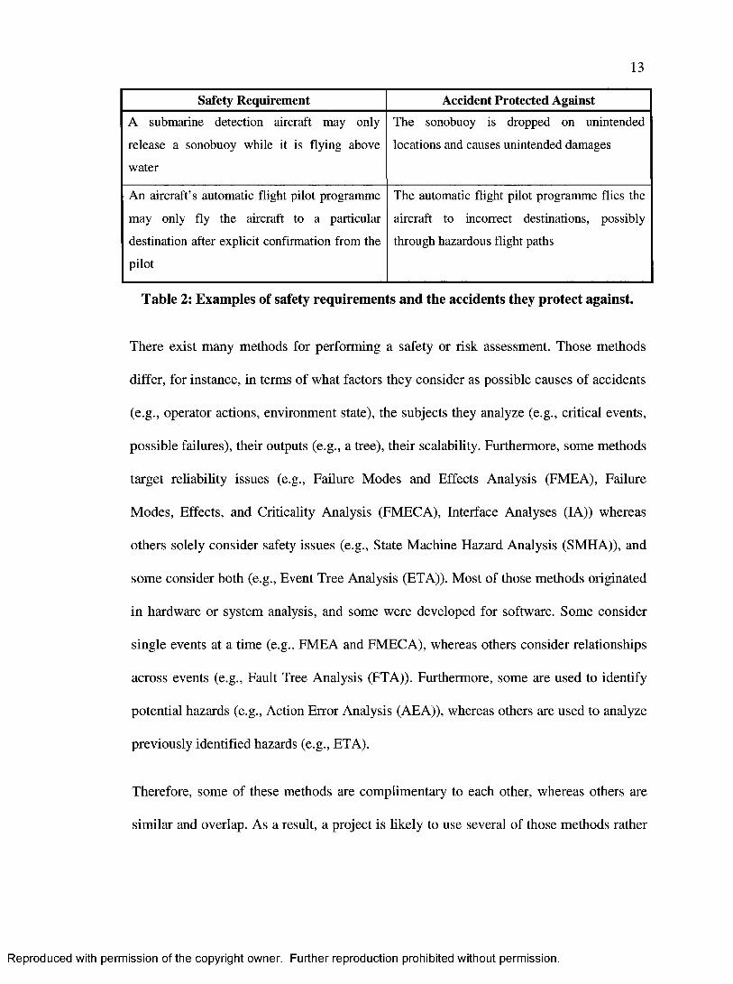
mandatory and critical element to developing a safety-critical system. Table 2 provides
examples of safety requirements and the potential accidents they protect against.
Reproduced with permission of the copyright owner. Further reproduction prohibited without permission.
13
Safety Requirement Accident Protected AgainstA submarine detection aircraft may only
release a sonobuoy while it is flying above
water
The sonobuoy is dropped on unintended
locations and causes unintended damages
An aircraft’s automatic flight pilot programme
may only fly the aircraft to a particular
destination after explicit confirmation from the
pilot
The automatic flight pilot programme flies the
aircraft to incorrect destinations, possibly
through hazardous flight paths
Table 2: Examples of safety requirements and the accidents they protect against.
There exist many methods for performing a safety or risk assessment. Those methods
differ, for instance, in terms of what factors they consider as possible causes of accidents
(e.g., operator actions, environment state), the subjects they analyze (e.g., critical events,
possible failures), their outputs (e.g., a tree), their scalability. Furthermore, some methods
target reliability issues (e.g., Failure Modes and Effects Analysis (FMEA), Failure
Modes, Effects, and Criticality Analysis (FMECA), Interface Analyses (IA)) whereas
others solely consider safety issues (e.g., State Machine Hazard Analysis (SMHA)), and
some consider both (e.g., Event Tree Analysis (ETA)). Most of those methods originated
in hardware or system analysis, and some were developed for software. Some consider
single events at a time (e.g., FMEA and FMECA), whereas others consider relationships
across events (e.g., Fault Tree Analysis (FTA)). Furthermore, some are used to identify
potential hazards (e.g., Action Error Analysis (AEA)), whereas others are used to analyze
previously identified hazards (e.g., ETA).
Therefore, some of these methods are complimentary to each other, whereas others are
similar and overlap. As a result, a project is likely to use several of those methods rather
Reproduced with permission of the copyright owner. Further reproduction prohibited without permission.
14
than just one. Examples of those methods are listed in Table 7 of Appendix A. Those
methods are discussed in many references, and a summary of them is presented in [1].
2.2 Safety-Related Standards
Many industrial standards exist for system and software safety. Some are common to all
industry sectors (e.g., IEC 61508-3 on software requirements for the functional safety of
electrical/electronic/programmable electronic systems) whereas others are industry
specific (e.g., CENELEC 50128 for Railway applications). Table 8 of Appendix B lists
some of these standards that relate to safety, or reliability due to its relation to safety.
Hermann provided a high-level summary for those standards, or some of their earlier
versions, in [9].
RTCA DO-178B [4] is the de-facto safety-related standard for developing software to run
in aerospace systems. It is also known as the “airworthiness” standard. Consequently,
engineers whose responsibilities includes ensuring compliancy with the airworthiness
standard are known as “airworthiness engineers”.
In addition to developing safety-related requirements, standards usually have additional
certification-related requirements. Those requirements are not necessarily implemented in
software, but rather they represent information about the software that must be submitted
to the certification authorities. For example, the airworthiness standard requires that
developers submit information regarding the COTS software used in the system.
Moreover, it requires that the developers specify time-related functions, such as filters,
that are used in the system. Therefore, it is important to be able to gather such
information easily about the software.
Reproduced with permission of the copyright owner. Further reproduction prohibited without permission.

15
DO-178B realizes that not all software components in an airborne system have the same
impact on the safety of the aircraft and its occupants. For example, the failure of software
that controls the altitude of an aircraft is much less acceptable than the failure o f the
software that controls the aircraft VCR for watching movies. This is because the failure
of the former may significantly reduce the aircraft’s chances of a safe flight. The failure
of the latter, however, does not have such effects as long as the VCR is isolated from
other safety-critical software. As a result, DO-178B classifies software failure conditions
into the following five categories [4]:
1. Catastrophic: A failure condition of this type would prevent continued safe flight
and landing of the aircraft. A software component whose failure may result in
failure condition of this category is known as a level A software component, and
is said to have airworthiness level A.
2. Hazardous/Severe-Major: A failure condition of this type would introduce
operating conditions that would severely reduce the ability of the aircraft crew to
cope with them to the extent where there would be large reductions in system
safety, the inability of the crew to perform tasks accurately and completely, and
potential fatal injuries. A software component whose failure may result in failure
condition of this category is known as a level B software component, and is said
to have airworthiness level B.
3. Major: A failure condition of this type would introduce operating conditions that
would severely reduce the ability of the aircraft crew to cope with them to the
extent where there would be significant reductions in system safety and crew
Reproduced with permission of the copyright owner. Further reproduction prohibited without permission.
16
efficiency, significant increase in crew workload and occupant discomfort, and
potential injuries. A software component whose failure may result in failure
condition of this category is known as a level C software component, and is said
to have airworthiness level C.
4. Minor: A failure condition of this type would introduce operating conditions that
can be handled by the crew, but may include a slight increase in the crew’s
workload or occupant discomfort, and a slight reduction in safety. A software
component whose failure may result in failure condition of this category is known
as a level D software component, and is said to have airworthiness level D.
5. No Effect: A failure condition of this type does not impact the system safety of the
aircraft, nor does it increase the aircraft crew’s workload. A software component
whose failure may result in failure condition of this category is known as a level E
software component, and is said to have airworthiness level E.
It should be noted, however, that there exists a difference between the concepts of
“airworthiness” and “safety”. The airworthiness standard, like many other safety-related
standards, defines different levels of impact on safety called “failure condition
categories” and “software levels”. However, it defines the failure condition categories
and the software levels based on the “severity of failure conditions on the aircraft and its
occupants” [4]. This is different from Leveson’s definition of safety, which was stated as
“the freedom from accidents or losses” [1]. While safety is the freedom from accidents or
losses, airworthiness is therefore the freedom from accidents or losses with respect to the
aircraft and its occupants. Thus, airworthiness is a subset of safety, and safe software is
Reproduced with permission of the copyright owner. Further reproduction prohibited without permission.

17
airworthy but airworthy software is not necessarily safe. For example, the first safety
requirement in Table 2 of page 13 is not necessarily an airworthiness requirement,
whereas the second one is.
2.3 Challenges in Software Safety
The NASA Langley Research Center, which has long cooperated with the Federal
Aviation Administration (FAA) on research about software engineering methods for
aerospace applications, conducted a research programme called Streamlining Software
Aspects of Certification (SSAC). This programme included an extensive survey to
identify the challenges in developing safety-critical software for aerospace systems.
Hayhurst and Holloway have documented results of this research in [10].
Hayhurst and Holloway of the NASA Langley Research Center identified “the challenge
of accurately communicating requirements between groups of people” as “the root of
many of the current challenges” in software safety [10]. They presented the
communication challenge as a combination of the following two major communication
channels:
1. Between regulatory people (e.g. certification authorities) and systems people (e.g.
systems engineers and airworthiness engineers).
2. Between systems people (e.g. systems engineers and airworthiness engineers) and
software people (e.g. software engineers).
Since systems engineers and safety/airworthiness engineers need to communicate with
the certification authorities, they need to have insight into the software and its sfety
Reproduced with permission of the copyright owner. Further reproduction prohibited without permission.

18
compliance aspects. The fact that they are unlikely to be experienced in software
engineering makes their responsibilities even more challenging. Moreover, software is
continuously changing and it is likely that the software engineers significantly outnumber
safety engineers. Therefore, it is essential to be able to achieve insight into the software’s
compliance aspects at relatively low costs. Such insight could be the ability to easily
monitor the software engineers’ progress with respect to the safety requirements and the
compliance with the certification requirements of the software.
Hayhurst’s and Holloway’s survey also found out that “requirements definition is
difficult” [10]. This undoubtedly contributes to the communication challenges between
the various people groups. For example, systems engineers may define requirements that
software engineers find unusual or expensive. If software engineers better understand the
needs behind the requirements, then they may be able to propose solutions that are more
cost effective. The software engineers’ misinterpretation of the requirements may also be
due to their lack of experience in safety. In fact, their lack of experience in safety often
causes them to confuse safety with reliability. In many instances, software engineers
cannot clearly define software safety without having prior background knowledge or
experience.
2.4 Usage Scenarios for Safety Information
Based on the discussion in sections 2.1 - 2.3, safety information is used by many
stakeholders as described in the use case diagram in Figure 2.
Reproduced with permission of the copyright owner. Further reproduction prohibited without permission.

19
Usage Scenarios for Safety Information
USAGE 2 Design Safety
Requirements in Systems
USAGE 1 Provide Safety Requirements
Safety Engineers Airworthiness Engineers
Software EngineersUSAGE 3
Record and Justify Design Decisions
USAGE 4 Monitor Safety
USAGE 5 Get Safety InformationCertification Authorities
(3rd Parties)
Figure 2: Usage scenarios for safety information.
The usage scenarios are:
USAGE 1 Provide Safety Requirements: Safety and airworthiness engineers
perform a safety assessment of the system being designed or modified.
As discussed in section 2.1, such a safety assessment results in safety
requirements, a subset of which will be allocated to software and
communicated to the software engineers. The software engineers will
then design and implement the software according to the safety
information and requirements. Thus, this usage scenario represents the
process of communicating safety information from the safety and
airworthiness engineers to the software engineers.
USAGE 2 Design Safety Requirements in Systems: Once the software engineers are
informed with the safety requirements allocated to software, they design
the software system with the safety requirements in mind. Then, they
implement it such that it meets all the safety requirements. Thus, this
Reproduced with permission of the copyright owner. Further reproduction prohibited without permission.

20
usage scenario represents the process of designing and implementing the
software system according to the safety requirements.
USAGE 3 Justify Design Decisions: Not only must the software engineers design
the software to meet the safety requirements, but they must justify their
design decisions as well. Such justification should explain the rationale
for the architecture and design details. In practice, architectural and
major design decisions are documented in separate documents, which
makes it separate from the software model. Furthermore, detailed design
decisions normally appear as plain text comments in the source code,
which makes it hard for safety and airworthiness engineers to obtain
justifications for the various design decisions. Thus, this usage scenario
represents the process of justifying and documenting design decisions so
that they can be easily obtained in the future.
USAGE 4 Monitor Safety: The safety and airworthiness engineers continuously
monitor the safety of the system, including the software, over the
project’s lifecycle. In order to do so, they need to consider how the
software engineers designed the software (USAGE 2) according to the
safety requirements they were provided with (USAGE 1). The software
engineers’ justifications for the design decisions (USAGE 3) will also be
considered. Then, the safety and airworthiness engineers can assess this
information and discuss any issue with the software engineers. This
ensures that the software’s safety is continuously improving during the
software’s lifecycle so that it meets the final safety objectives of the
Reproduced with permission of the copyright owner. Further reproduction prohibited without permission.

21
system. In addition, this usage scenario provides additional confidence
that the system certification process will go more smoothly. Thus, this
usage scenario represents the process of continuously monitoring the
design and implementation of the software in accordance with the
system’s overall safety requirements.
USAGE 5 Get Safety Information: Once it is time to certify the system, which is
usually towards the end of the development lifecycle, safety and
certification information is submitted to the certification authorities. This
information includes the safety requirements (USAGE 1), the software
design (USAGE 2), the justification of the software design (USAGE 3)
given the safety requirements of the software, and the process used to
continuously monitor the system and software safety over the
development lifecycle (USAGE 4). If safety and airworthiness engineers
continuously and appropriately monitor safety over time (USAGE 4),
then certification should be a much easier experience. Thus, this usage
scenario represents the process of obtaining the appropriate safety
information, system and software design, justification of the design from
a safety perspective, and the method used for monitoring safety during
the development lifecycle for the purpose of submitting this information
to the certificatrion authorities.
If the safety information is captured in a UML model, then this would easily facilitate the
above mentioned usage scenarios. UML models are developed for software systems
anyways, so using it to facilitate the usage scenarios and address the challenges in
Reproduced with permission of the copyright owner. Further reproduction prohibited without permission.
22
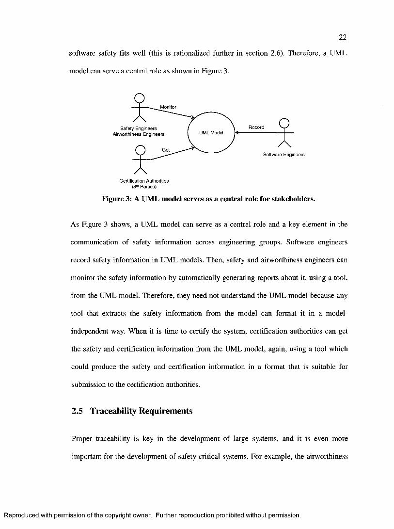
software safety fits well (this is rationalized further in section 2.6). Therefore, a UML
model can serve a central role as shown in Figure 3.
Monitor
RecordSafety Engineers Airworthiness Engineers UML Model
G e tSoftware Engineers
Certification Authorities (3rd Parties)
Figure 3: A UML model serves as a central role for stakeholders.
As Figure 3 shows, a UML model can serve as a central role and a key element in the
communication of safety information across engineering groups. Software engineers
record safety information in UML models. Then, safety and airworthiness engineers can
monitor the safety information by automatically generating reports about it, using a tool,
from the UML model. Therefore, they need not understand the UML model because any
tool that extracts the safety information from the model can format it in a model-
independent way. When it is time to certify the system, certification authorities can get
the safety and certification information from the UML model, again, using a tool which
could produce the safety and certification information in a format that is suitable for
submission to the certification authorities.
2.5 Traceability Requirements
Proper traceability is key in the development of large systems, and it is even more
important for the development of safety-critical systems. For example, the airworthiness
Reproduced with permission of the copyright owner. Further reproduction prohibited without permission.

23
DO-178B standard [4] requires traceability across the development lifecycle. In fact, it
requires that at least the software design be traceable to the original high-level
requirements for all software of level D or higher. Therefore, it is important to be able to
trace design elements to the requirements.
Another important traceability requirement relates to the analysis of safety requirements.
For example, the first requirement in Table 2 states: A submarine detection aircraft may
only release a sonobuoy while it is flying above water. This can be rephrased to: The
ordnance (sonobuoy release) subsystem shall not release a sonobuoy if it is requested to
do so when the aircraft is not flying above water. This results in identifying the following
event of interest: The ordnance subsystem is requested to release a sonobuoy when the
aircraft is not flying above water. Furthermore, this also results in identifying a reaction
to this event, namely: The ordnance subsystem verifies that the aircraft is flying above
water, and forbids the sonobuoy from being released if it is not flying above water. Since
reactions are caused by events, it is important to ensure that every reaction is traceable to
the appropriate events
In summary, two important traceability requirements are:
1. Tracing software design elements to software requirements.
2. Tracing software reactions to software events.
2.6 UML APPROACH
Because the results of safety assessments are an important part of software developers’
work, they need to be appropriately communicated and implemented in the technical
Reproduced with permission of the copyright owner. Further reproduction prohibited without permission.

24
designs. Furthermore, certification information about the software is required for the
certification authorities. It is appropriate and useful to be able to represent the results of
safety assessments and certification information in UML diagrams because it is the
standard modeling language used by software developers throughout the world [2],
Currently, there does not seem to be a comprehensive UML profile specifically targeted
towards modeling safety-related concepts driven from safety standards (see section 4). If
it existed, such a UML profile would help bridge the gap between the system’s safety
assessment (performed by safety engineers) and the software design (performed by
software engineers). The safety engineers need not necessarily understand the UML
profile, but they will need the information that is reprented by the profile. See Figure 4
for an illustration.
Safety and Airworthiness engineers produce a list of safety requirements and certification information
Software and system engineers use UML to model their systems, which must conform to the safety and certification requirements
X \Safety Engineers Airworthiness Engineers
Generate Safety \ Requirements \
and Certification IInformation /
An appropriate UML safety profile bridges this gap by allowing software and system engineers to include safety requirements and certification information in their UML models. In turn, they may discover additional safety or certification information that are communicated back to the safety and airworthiness engineers.
Use Unified Modeling Language
(UML)
nformation Flow
Software Engineers System Engineers
Figure 4: Role of a UML safety profile in the development process.
2.6.1 Disadvantages
Using this approach has the following disadvantages:
Reproduced with permission of the copyright owner. Further reproduction prohibited without permission.
25
1. Is an extra step to the development process: Most software development
processes do not require documenting safety-related properties on design models.
Therefore, this approach will be an additional step to most software development
processes.
2. Requires that software engineers consider a topic they are likely to have little
experience in - safety: Safety is a specialized topic of software engineering. Since
software engineers may come from backgrounds where they were developing
non-safety-critical systems, they may not have sufficient knowledge and
experience in this topic.
2.6.2 Advantages
Using this approach has the following advantages:
1. Results in safer and higher quality software: By representing safety requirements
and constraints on UML diagrams, the engineers are forced to consider them and
use them to design and implement the systems.
2. Enables the possibility o f reusing the results o f a safety assessment through
software models: Performing a safety assessment, like a risk assessment, is costly
and time consuming. Therefore, representing the results of a safety assessment on
UML diagrams allows it to be reused whenever the design is reused instead of
reassessing the new or modified system from scratch. This is important when an
organization is designing similar systems.
Reproduced with permission of the copyright owner. Further reproduction prohibited without permission.

26
3. Improves communication between safety engineers and software engineers:
Software developers will have a better understanding of the safety engineers’
requirements. This will allow software engineers to better understand and review
the results of the safety assessment. As a result, software engineers will be able to
provide feedback regarding the safety assessment.
4. Improves documentation o f safety-related properties: Appropriate documentation
is required by many standards including the MIL-STD-498 [11], and its
replacement IEEE/ELA 12207 [12], which is one of the most referenced software
development documentation standards. Documenting the results of a safety
assessment in UML provides a step in that direction.
5. Increases participation o f software engineers in the safety assessment: This
approach drives software engineers to think about the results of the safety
assessment because it is represented in UML. Therefore, they will implicitly
perform additional analyses as part of their job to design and implement the
software. As a result, they may discover additional safety requirements and
constraints, which can then be communicated back to the safety assessment
process.
6. Increases level o f formalism: The results of the safety assessment will be
represented using methods that are more formal than plain text English. This helps
introduce the benefits of using formal methods, such as being able to detect
conflicting or ambiguous requirements. In addition, this will make it easier for
Reproduced with permission of the copyright owner. Further reproduction prohibited without permission.

27
tools to use this information to help the engineers design, implement, and verify
systems.
7. Maps safety-related properties to source code: This approach allows safety-
related properties to be represented in UML models. In the software development
process, the source code is directly traceable to UML models. Therefore, this
approach allows safety-related properties to be mapped to the source code through
the UML designs. This improves traceability, which is often required by many
standards and is critical in large programmes.
8. Lower cost to use since UML is known in the software community: A UML safety
profile builds on the engineers’ knowledge of UML. Therefore, there is no
additional cost to train the software engineers to use UML. They only need to be
aware of the UML profile specifics and how it builds on top of UML. This should
be inexpensive as software engineers should already be experienced with UML
and the tools that support it.
9. Emphasizes a “develop in safety” culture: In her book on software safety [1],
Nancy Leveson stressed the need for a “develop in safety” culture in
organizations. This UML approach emphasizes Leveson’s point as it involves the
software engineers and developers in the safety aspects of the software.
10. Supports the MDA initiative: The MDA initiative [3] is a promising approach
that, in conjunction with UML, seems to be the future of software development. It
argues that design should be modeled appropriately first, which then allows the
engineers to forward-generate the implementation (e.g. software code) from the
Reproduced with permission of the copyright owner. Further reproduction prohibited without permission.
28
high-level designs using appropriate computer tools. This is a very active research
area that is projected to be the future of the development process as it will
increase the level of automation. Such a UML profile allows describing the safety
aspects in the software model, which would in turn be used in the MDA approach.
11. Makes life o f engineers easier: For the engineers, this means that relevant safety
information will be represented in a language that they understand, namely UML,
rather than having to read other informal documents that risk being ambiguous.
2.6.3 Requirements of an Effective UML Profile
Based on the previous discussion, we identify that the requirements of an effective UML
profile are:
REQ 1 The profile shall provide insight into the software’s compliance aspects with
airworthiness, and such evidence o f compliance shall be obtainable at low
costs: In essence, the cumulative cost of training the engineers to use the
profile and extracting regular software compliance reports for progress
tracking shall be less than the cost of collecting software compliance
evidence when the profile is not used.
REQ 2 The profile shall allow the software engineers to relate technical solutions
to the specific airworthiness requirements: Therefore, it shall be possible to
exactly determine the software design and source code units that are
responsible for satisfying each airworthiness requirement.
Reproduced with permission of the copyright owner. Further reproduction prohibited without permission.

29
REQ 3 The profile shall have clear language semantics with respect to safety and
airworthiness: For example, the profile shall not assume that safety is
simply reliability or some other concept - it shall recognize safety and
airworthiness as a separate quality domain. This will enable better
representation of requirements as well as improve the software engineers’
understanding and ability to distinguish between safety and other concepts
such as reliability.
REQ 4 The profile shall model technical solutions using machine-readable
extension mechanisms that increase the level o f formalism: In other words,
specific domain stereotypes, tags, and constraints shall be preferable to
general purpose comments. In addition, the extensions shall allow software
engineers to identify various kinds of technical solutions. Examples of
technical solutions include safety monitors and multiple-version dissimilar
software. This is particularly useful when developing software under high
software airworthiness (see section 2.2) levels when formal methods are
more likely to be used, and when models are reused across projects.
REQ 5 The profile shall support, or be easily scalable to, developing software
under high airworthiness levels: Different airworthiness levels have
different compliance requirements. For example, level C and above require
tracing source code to low-level requirements and tracing low-level
requirements to high-level requirements, whereas levels D and E do not
have such requirements [4], As another example, high software levels
require checking that requirements are compatible with the target computers
Reproduced with permission of the copyright owner. Further reproduction prohibited without permission.
30
on which the software is deployed. Refer to annex A in [4] for a list of
objectives per software level.
REQ 6 The profile shall favour language semantics that are meaningful to both
software engineers and airworthiness engineers fo r concepts that both
engineering groups need to discuss: Therefore, it will improve
communication between the two groups.
REQ 7 The profile shall favour representing airworthiness requirements using
machine-readable extension mechanisms: Thus, it shall define some
airworthiness-specific stereotypes, tags, and constraints that are
parameterizable. Again, this is particularly useful when developing software
under high-software levels because that is when formal methods are more
likely to be used due to their ability to prove correctness. In addition, this is
also useful when models are to be reused across projects.
Reproduced with permission of the copyright owner. Further reproduction prohibited without permission.
31
3 SAFETY-RELATED CONCEPTS
This section describes airworthiness-related concepts that were extracted from the
airworthiness standard, RTCA DO-178B [4]. Since airworthiness is a subset of safety
(see end of section 2.2), all of the identified airworthiness-related concepts are safety-
related concepts. This does not necessarily mean that those concepts are the only ones
needed for all safety-critical applications including transportation, medical, nuclear, and
other industries. However, they should be enough for any development under the
airworthiness standard [4], which is the goal of this research.
Since airworthiness is a subset of safety, airworthiness-related concepts will be referred
to with their general term, safety-related concepts, in the remainder of this document.
This is to emphasize that they are not restricted to airworthiness even though they
resulted from analysing the airworthiness standard.
Ensuring software safety has many concerns that impact other qualities of service. As a
result, the extracted safety-related concepts form a long list of concepts related to many
concerns and qualities of service. Hence, it is important to group concepts that are most
related together, which will also improve clarity and give the reader the general goal of
each concept. For example, consider the following safety-related requirement:
An aircraft shall ensure that its landing wheels are deployed when the
aircraft’s altitude is less than 100 meters
Reproduced with permission of the copyright owner. Further reproduction prohibited without permission.

32
The following concerns are relevant for designing and implementing the safety-critical
software assigned with the above requirement:
1. It must be safe so that the aircraft does not hit the ground with the landing wheels
not deployed (i.e. when they are in their compartments). Software safety is the
ability of the software to execute within its system context without contributing to
hazards, which may lead to accidents or losses [1].
2. It must be reliable so that it correctly implements the requirement by ensuring
that landing wheels are deployed when the altitude is less than 100 meters.
Software reliability is the capability of the software system to offer continued
service, or more specifically to maintain a specified level of performance when
used under specified conditions [5].
3. It must have high integrity by providing precise and accurate results so that an
altitude of less than 100 meters is not interpreted to be larger than 100 meters (and
thus causing the aircraft not to deploy its wheels when it should). Software
integrity is the capability of the software system to produce the expected quality
of service of the correct functionality delivered by the software [5].
4. It must have high performance capabilities, so that the landing wheels are
deployed when the aircraft’s altitude drops to less than 100 meters even when it
does so quickly in a fast descent such as the case in an emergency. Software
performance refers to the timeliness aspects of how software systems behave, and
sometimes it refers to the relationship between the services provided and the
utilization of resources [5].
Reproduced with permission of the copyright owner. Further reproduction prohibited without permission.

33
5. It must provide concurrent control so that the landing wheels are deployed even if
pilot is already using the system to perform other functionality through the user
interface. Software concurrency refers to the concurrent and temporal consistency
of data and software elements [5].
6. It must be certifiable as vendors of such safety-critical systems often require them
to be certified by an external third-party certification authority. Certification is the
legal recognition by the certification authority that a product, service, organization
or person complies with the requirements [4],
7. It must be properly designed so that non-critical software, such as a language
dictionary, is decoupled from highly safety-critical software, such as the software
interfacing with the landing wheels and the altitude sensors, to ensure that
software bugs in non-critical software do not cause the critical software to fail.
8. It must be independent of the various software configurations that may be loaded
into the system to configure it such as English and French dictionaries to
customize the user interface. Software configuration, which is not the same as
software configuration management, is the concept of having multiple software
configurations or settings, each of which has a different set of functionalities and
behaviours than the others.
Notice that while the concerns above describe various software quality categories, they
all contribute to safety in some way. With that in mind, it is important to classify all of
the extracted safety-related concepts into quality categories that best describe each related
group of concepts. Those categories help the reader have a better understanding of the
Reproduced with permission of the copyright owner. Further reproduction prohibited without permission.
34
general goal of each concept, and they provide guidance on what to look for when
attempting to describe a specific concept.
3.1 Concept Identification and Categorization
The selected standard, the airworthiness RTCA DO-178B standard [4], was analysed and
a list of safety-related concepts was extracted. Those safety-related concepts are not
solely safety concepts, and hence the rationale behind using the term “safety-related
concepts” rather than simply “safety concepts” - in fact, many of those concepts are
primarily non-safety concepts, such as reliability concepts, fault-tolerance concepts,
certification concepts, and others. The “primarily” keyword identifies the category with
which a concept is most associated. For example, fault tolerance is associated with
reliability and, therefore, is a primarily reliability concept that also affects safety in some
way.
To clarify and group related concepts together, the extracted safety-related concepts are
classified in this research into the following safety-related quality categories:
1. Primarily safety concepts: The concepts listed in this category are software
concepts that describe the software’s safety aspects in the context of the system in
which it is used. Software safety is the ability of the software to execute within its
system context without contributing to hazards, which may lead to accidents or
losses [1]. Examples of these concepts include safety-monitoring techniques and
software levels. These concepts are listed and described in section C .l of
Appendix C.
Reproduced with permission of the copyright owner. Further reproduction prohibited without permission.
35
2. Primarily reliability concepts: The concepts listed in this category are software
concepts that describe the software’s reliability aspects. However, they also
impact the safety of the software because of the relationship between software’s
reliability and safety - reliability measures the probability of failure, whereas
safety measures the consequences of those failures [5], Software reliability is the
capability of the software system to offer continued service, or more specifically
to maintain a specified level of performance when used under specified conditions
[5]. Examples of primarily reliability concepts include exception handling and
fault tolerance. These concepts are listed and described in section C.2 of
Appendix C.
3. Primarily integrity concepts: The concepts listed in this category are software
concepts that describe the software’s integrity aspects. However, they also impact
the safety of the software because of the relationship between software’s integrity
and safety. Software integrity is the capability of the software system to produce
the expected quality of service of the correct functionality delivered by the
software [5]. Examples of primarily integrity concepts include accuracy and
precision: Inaccurate data may cause the safety-critical system to behave in a non
safe way. As an example, consider an aircraft the needs to know when to deploy
the landing wheels - it must have an accurate value of the altitude so that it
deploys the landing wheels when it should. These concepts are listed and
described in section C.3 of Appendix C.
4. Primarily performance concepts: The concepts listed in this category are software
concepts that describe the software’s performance aspects. However, they also
Reproduced with permission of the copyright owner. Further reproduction prohibited without permission.
36
impact the safety of the software because of the relationship between software’s
performance and safety. Software performance refers to the timeliness aspects of
how software systems behave, and sometimes it refers to the relationship between
the services provided and the utilization of resources [5]. In this document,
performance concepts include schedulability and time concepts. Examples of
primarily performance concepts include scheduling strategies (e.g. round robin,
rate monotonic) and time-related (e.g. filters) functions. For example, an aircraft’s
scheduling software must schedule safety-critical tasks with priorities higher than
non safety-critical tasks. These concepts are listed and described in section C.4 of
Appendix C.
5. Primarily concurrency concepts: The concepts listed in this category are software
concepts that describe the software’s concurrency aspects. However, they also
impact the safety of the software because of the relationship between software’s
concurrency and safety. Software concurrency refers to the concurrent and
temporal consistency of data and software elements [5]. Examples of primarily
concurrency concepts include multi-tasking and active software components,
which may be safety-critical. These concepts are listed and described in section
C.5 of Appendix C.
6. Primarily certification concepts: The concepts listed in this category are software
concepts that describe the software’s certification aspects. However, they also
impact the safety of the software because of the relationship between software’s
certification and safety. Certification is the legal recognition by the certification
authority that a product, service, organization or person complies with some
Reproduced with permission of the copyright owner. Further reproduction prohibited without permission.
37
requirements. Such certification comprises the activity of technically checking the
product, service, organization or person and the formal recognition of compliance
with the applicable requirements by issue of a certificate, license, approval or
other documents as required by national laws and procedures [4]. Examples of
primarily certification concepts include certification requirements (e.g. specifying
hardware/software interfaces) and software traceability. These concepts are listed
and described in section C.6 of Appendix C.
7. Primarily design concepts: The concepts listed in this category are software
concepts that describe the software’s design aspects. However, they also impact
the safety of the software because of the relationship between software’s design
and safety. These generally impact areas such as the quality, clarity, and
maintainability of the model and the source code. The impact of these decisions
on the use of the end product is usually less defined than those of other quality
categories. Examples of primarily design concepts include software coupling and
software complexity. These concepts are listed and described in section C.7 of
Appendix C.
8. Primarily configuration concepts: The concepts listed in this category are
software concepts that describe the software’s configuration aspects. However,
they also impact the safety of the software because developing multiple-
configuration software is more challenging than developing single configuration
software due to the changing behaviour. As a result, it is more challenging to fully
predict the behaviour of the software, especially when the user of the software can
change the configuration (e.g. by changing memory bits or loading customized
Reproduced with permission of the copyright owner. Further reproduction prohibited without permission.

38
look up tables). Software configuration, which is not the same as software
configuration management, is the concept of having multiple software
configurations or settings, each of which has a different set of functionalities and
behaviours than the others. Choosing the desired software configuration is usually
performed by the user rather than the software developer. Examples of primarily
configuration concepts include option-selectable software and user-modifiable
software. These concepts are listed and described in section C.8 of Appendix C.
An 8-dimensional space is needed to fully describe the relationships across all safety-
related quality categories identified above. For simplicity, let us assume that reliability,
integrity, performance, concurrency, certification, design, and configuration concepts sets
form mutually exclusive sets. If we fix values for 6 dimensions, then we can arrive at a 2-
dimensional view that shows the relationship between safety and each of the other
identified safety-related quality categories independently of their cross relationships. This
view is somehow simplistic but it is useful for illustration purposes. It is shown in Figure
5 below.
Figure 5 shows that the identified quality categories are related to safety. In other words,
there exist concepts that are present in more than one quality category, one of which is
the safety quality category. All of the concepts extracted from the airworthiness standard
belong to at least the safety quality category. In addition, some of those concepts also
belong to categories other than the safety category. For example, a “shared resource” is a
“concurrency” concept because multiple flows of control may be competing for access to
it. This will also impact the performance aspects of the software. Moreover, it is also
relevant to the “design” aspects of the software because the way it will be used is a result
Reproduced with permission of the copyright owner. Further reproduction prohibited without permission.

39
of design decisions. Finally, all of these aspects might impact the “safety”-aspects if one
or more of the competing flows of control are executing a safety-critical software section.
PurelyReliability
PurelyIntegrity
PurelyPerformance
PurelyConcurrency
PrimarilyReliability
Primarilyintegrity
PrimarilyPerformance
Primarily Concurrency I
Primarily Safety
Primarily Primarily Primarily1 Certification ; Design Configuration 1| Purely i Purely Purely
Certification Design | ConfigurationSafety-Related Concepts
(concepts of interest)
Figure 5: Relationship between safety and other safety-related quality categories
assuming that those categories form mutually exclusive sets.
Regardless of its category, each concept can be one of three different kinds:
1. It can be a “safety entity”, which is software that may contribute, positively or
negatively, to the overall safety level of the system or software. Furthermore, a
safety entity can interact with another safety entity. An example of a safety entity
would be identifying a particular software component as a fault monitor. A fault
monitor (one safety entity) is used to monitor particular functions (other safety
entities) to detect faults that could occur and cause the system to enter a
hazardous state. If a fault monitor detects such a fault, it could then perform
appropriate actions to prevent the system from entering hazardous states.
Therefore, the fault monitor is a safety entity whose purpose is to increase the
overall level of safety of the system.
Reproduced with permission of the copyright owner. Further reproduction prohibited without permission.

40
2. It can be a “safety attribute”, which is a concept that describes a safety property,
such as the safety level or impact on safety, of safety entities. For example, the
fault monitor described above may be used to detect specific faults or unusual
results and behaviours. For example, what if a particular software function that is
used to indicate the altitude of the aircraft provides output that says that the
aircraft has a negative altitude? This is clearly an incorrect result. Assume that a
fault resulting in this scenario is detectable by the fault monitor described earlier.
In this case, this specific fault can be used as a safety attribute of the fault
monitor. In other words, the complete specification of the fault monitor safety
entity will explicitly state through one of its safety attributes that it can detect this
fault.
3. It can be a “safety method”, which is an activity, technique, or a process that may
measure or impact, positively or negatively, the safety level of safety entities. For
example, a scenario that describes the fault monitoring example above covers
many concepts such as fault monitoring, faults, and possibly many others that are
related to the ability of monitoring software against faults that they may cause.
Therefore, all that discussion is centred around one concept, namely “fault
monitoring”. Thus, that scenario describes one “safety method” that is fault
monitoring.
The use of the word “safety” in safety entity, safety attribute, and safety method only
means that those concepts are safety-related. It does not assume that they increase the
level of safety.
Reproduced with permission of the copyright owner. Further reproduction prohibited without permission.

41
Figure 6 (a) formalises those definitions through a conceptual conceptual model. Notice
that each safety entity is described through safety attributes. Safety entities may interact
with each other, and they may implement safety methods (usually those that positively
impact safety). Safety methods may measure or impact, positively or negatively, the
safety level of safety entities. Figure 6 (b) describes the fault monitoring example
presented above, which is an instance of the conceptual model in Figure 6 (a).
interactswith recognizes
describedthrough monitors
SafetyAttribute Implements causes
measures or impacts safety ofimplements
improves safety of
SafetyMethod
SafetyEntity
faulMonitor:SafetvEntitv
faultMonitoring:SafetvMethod
Fault:SafetvAttribute
Safety Concept
monitoredComponent:SafetvEntitv
(a) Model (b) Fault monitoring example
Figure 6: Relationship across safety entities, attributes, and methods.
The safety-related concepts for each category are listed in Appendix C. They are
described according to the context in which they appear within the airworthiness
standard, RTCA DO-178B [4]. Those concepts are then refined into a terminology that is
more suitable for modeling software. The refined concepts, along with their descriptions
and their inter-concept relationships, are presented in section 3.2.
3.2 Concept Refinement
Section 3.1 and Appendix C introduced 65 safety-related concepts that were found
relevant for developing airworthiness-compliant software. They were then grouped
Reproduced with permission of the copyright owner. Further reproduction prohibited without permission.

42
according to their software quality category. In this section, those concepts are refined for
the following reasons:
1. Removing duplicate concepts: In some instances, seemingly different concepts
appeared in the airworthiness standard where, in reality, they can be represented
using a single concept or term. This is because the same fundamental software
concept can appear in different forms in airworthiness-related applications.
Examples are presented below.
Consider, for example, the two following primarily reliability concepts exactly as
they appear in the airworthiness standard: Multiple-Version Dissimilar Software
and Software Redundancy (see Appendix C.2 for definitions). They revolve
around the same software concept, which is that of using multiple software
components that have the same functionality but different implementations. It
would be unnecessarily confusing to use two different terms to denote the same
concept. As a result, a single refined term is provided to model both of those
concepts, which is the “replicated” concept to denote software replication or
redundancy.
2. Grouping concepts: Some concepts are in fact examples of a more general
concept.
Consider the following concepts: Safety Monitoring, Loadable Software
Indicator, Safeguard, Safety Feature (primarily safety concepts defined in
Appendix C .l); Error Detection, Fault Detection, Fault Containment (primarily
reliability concepts defined in Appendix C.2); Integrity Check, Software Protector
(primary integrity concepts defined in Appendix C.3); Error Prevention
Reproduced with permission of the copyright owner. Further reproduction prohibited without permission.

43
(primarily design concept defined in Appendix C.l). They are applications of a
single software-concept that is “Monitor” . A “monitor” monitors the activity of
other software components to detect unusual, potentially hazardous, events.
3. Precise definition o f details: Presenting each concept is a single entry in a list may
be misleading by giving the impression that it is the smallest level of detail. In
reality, each concept has many attributes that describe it, with each attribute
describing a single aspect of the concept. Examples are presented below.
For example, “Safety Requirement” is identified as a (primarily safety) safety-
related concept (Appendix C .l). However, it does not mention the specification of
safety requirements. When refining the “Safety Requirement” concept, we give it
an attribute called “specification” that can be used to specify the details of the
requirement. Therefore, a concept’s attribute is used to describe a specific aspect
or detail of it.
The rest of this section shows how the concepts and their relationships have been
formalized under the form of a conceptual model, i.e., a UML class diagram (section
3.2.1), describes the template we use to specify the concepts (section 3.2.2), and then
actually specifies the concepts (section 3.2.3). Appendix D provides additional details on
the relationships between concepts.
3.2.1 Conceptual Model
Before describing the details of the concepts, we introduce a conceptual model to list the
refined concepts and formalize the relationships among them (Figure 7—its elements are
Reproduced with permission of the copyright owner. Further reproduction prohibited without permission.

44
further described in section 3.2.3). Thus, the motivations for defining a conceptual model
for the refined concepts are:
1. It introduces a high-level presentation of the concepts and their relationships, thus
leaving out most attributes that are considered low-level details. This helps the
reader better understand the concepts and their relationships.
2. It formalises the relationships across the concepts, for instance by specifying
multiplicities on relationships.
3. It makes the definition and the use of the UML profile’s extensions (stereotypes,
tagged values, and constraints) in section 5 easier because the refined concepts are
designed to be more appropriate from a modeling point of view. Thus, many of
the profile’s extensions refer back to the refined concepts. In fact, the profile’s
stereotypes and tagged values are based on the refined concepts, their attributes,
and their relationships.
3.2.2 Concept Details
In this section, we describe the template we use in section 3.2.3 to define the concepts in
Figure 7. Each of the following describes one characteristic of a concept:
1. Definition: This presents a definition for the concept. It describes the concept and
gives its general purpose.
Reproduced with permission of the copyright owner. Further reproduction prohibited without permission.
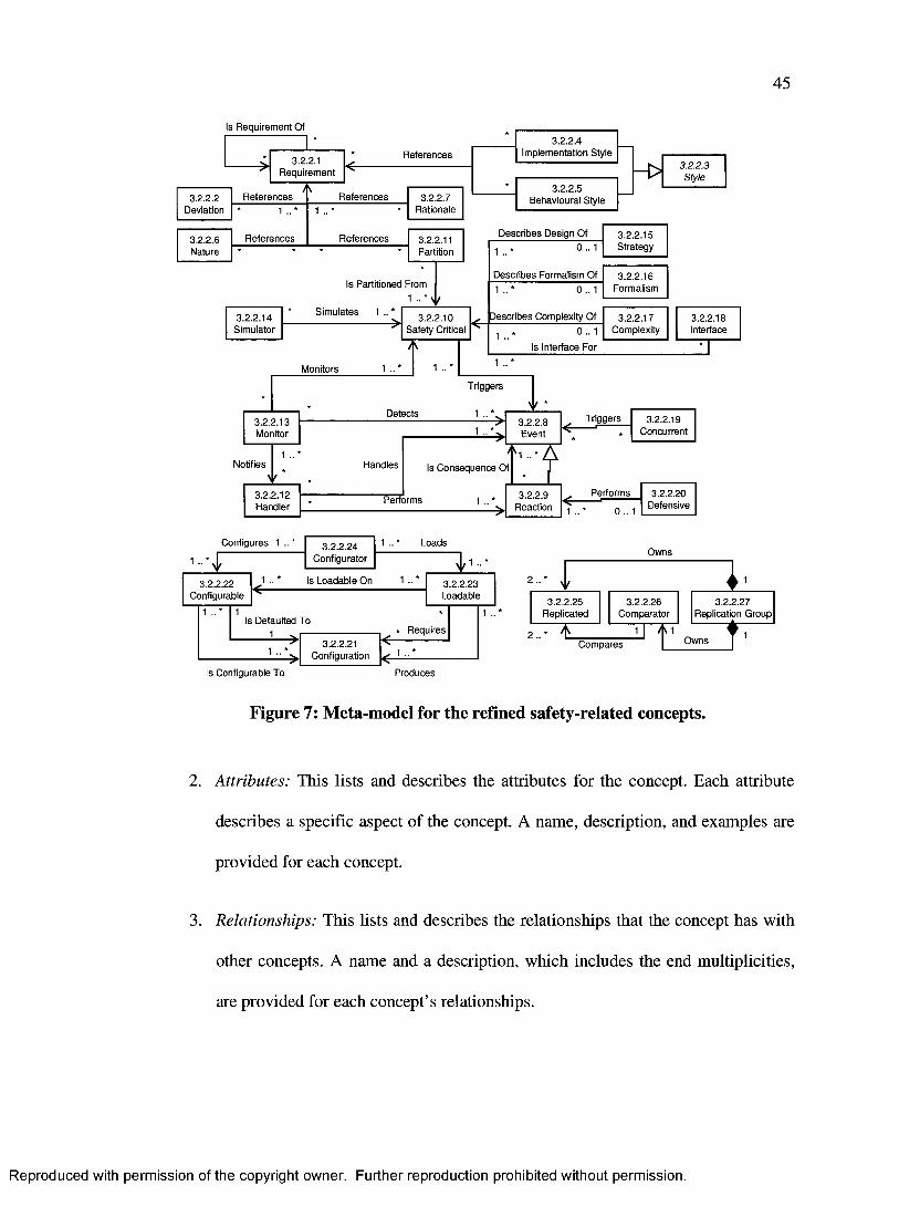
45
Is Requirement Of
3.2.2.1 Requirement
3.2.2.2 Deviation
References
3.2.2.6Nature
1
References
References
References1 . . '
3.2.2.7 Rationale
3.2.2.4 Implementation Style
3.2.2.5 Behavioural Style
3.2.2.3Style
References 3.2.2.11Partition
Is Partitioned From 1
3.2.2.14 * Simulates 1 .. * 3.2.2.10 Describes Complexity Of 3.2.2.17 3.2.2.18Simulator Safety Critical 1. . * 0 - 1 Complexity Interface
y Is Interface For " T '
Monitors 1 •• * 1 1
Describes Design Of
1 0 . . 13.2.2.15Strategy
Describes Formalism Of1 0 . . 1
3.2.2.16Formalism
3.2.2.13Monitor
Notifies
Detects
Triggers
1 *
1
1Handles
\ f3.2.2.12Handler
3.2.2.8 Triggers 3.2.2.19Event ------- Concurrent
Is Consequence Of
Performs 3.2.2.9 Reaction
Performs
1 0 . . 1
3.2.2.20Defensive
Configures 1 .. *
1 .. £3.2.2.24
ConfiguratorLoads
1
Owns1
3.2.2.22 1 .. * Is Loadable On 1 .. * 3.2.2.23Configurable Loadable
Is Defaulted To 1
1 .. *3.2.2.21
Configuration
Requires
\ f
1 .. *
2 .. *Compares
I3.2.2.25 3.2.2.26 3.2.2.27
Replicated Comparator Replication Group
Owns TIs Configurable To Produces
Figure 7: Meta-model for the refined safety-related concepts.
2. Attributes: This lists and describes the attributes for the concept. Each attribute
describes a specific aspect of the concept. A name, description, and examples are
provided for each concept.
3. Relationships: This lists and describes the relationships that the concept has with
other concepts. A name and a description, which includes the end multiplicities,
are provided for each concept’s relationships.
Reproduced with permission of the copyright owner. Further reproduction prohibited without permission.

46
4. Original Safety-Related Concepts: This lists the original safety-related concepts,
which were extracted from the airworthiness standard, RTCA DO-178B [4], and
presented in section 3.1 (and Appendix C), that this concept represents. Thus, this
information serves as additional justification for the concept, its attributes, and its
relationships.
The attributes of each concept are presented in a table. For example, the attributes of the
“Safety Critical” (section 3.2.3.10) refined concept are presented as follows:
Name Description Examples
Criticality Level Indicates the level of criticality (e.g.
airworthiness level, Safety Integrity
Level (SIL)), on some pre-defined
scale, such as the software level or
the failure condition category
For RTCA DO-178B [4]:
“A”, “B”, “C”, “D”, “E”
For IEC 61508 [24]:
“SIL 1”, “SIL 2”, “SIL
3”, “SIL 4”
... etc
Confidence Level Indicates the level of confidence, on
some pre-defined scale, that the
criticality level is satisfied
“High”, “Medium”,
“Low”, “80%”, “50%”,
... etc
Each row describes a single concept attribute. The first column (Name) specifies the
name of the attribute, the second column (Description) describes the attribute, and the
third column (Examples) provides examples for the value of the attribute.
Similarly, the relationships of each concept are presented in a table. For example, the
relationships of the “Safety Critical” (section 3.2.3.10) refined concept are presented as
follows:
Reproduced with permission of the copyright owner. Further reproduction prohibited without permission.

47
Name Description
Triggers Identifies zero or more “Event” instance that the “Safety Critical”
instance triggers
Each row describes a single concept relationship. The first column (Name) specifies the
name of the relationship, and the second column (Description) describes the relationship.
The description of the relationship identifies the concept at the other end of the
relationship as well as its multiplicity.
3.2.3 Concepts Specifications
The refined concepts are listed below in sections 3.2.3.1 to 3.2.3.27 in an order, different
from the alphabetical order, that we think will help the reader better understand them and
their relationships. For example, concept A is listed before concept B if concept B
references or depends on concept A.
Some of the concepts’ attributes presented below are specific to the developed system or
the development project. This is common for attributes whose type is an enumeration. In
such cases, this research does not attempt to define all the possible values. However, it
does present examples on what they could be. It is up to the software developers to define
the enumeration values that are relevant to the system being developed.
The term “design element” is used to indicate “a portion of the design” such as a class,
operation, collaboration (i.e. diagram), or relationship between classes. The design
element can be either hardware or software.
Reproduced with permission of the copyright owner. Further reproduction prohibited without permission.
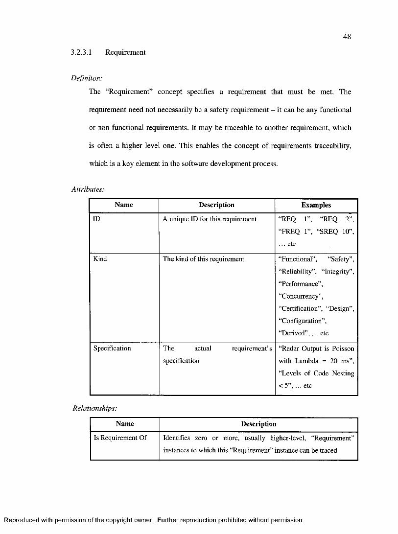
48
3.2.3.1 Requirement
Definiton:
The “Requirement” concept specifies a requirement that must be met. The
requirement need not necessarily be a safety requirement - it can be any functional
or non-functional requirements. It may be traceable to another requirement, which
is often a higher level one. This enables the concept of requirements traceability,
which is a key element in the software development process.
Attributes:
Name Description Examples
ID A unique ID for this requirement “REQ 1”, “REQ 2”,
“FREQ 1”, “SREQ 10”,
... etc
Kind The kind of this requirement “Functional”, “Safety”,
“Reliability”, “Integrity”,
“Performance”,
“Concurrency”,
“Certification”, “Design”,
“Configuration”,
“Derived”, ... etc
Specification The actual requirement’s
specification
“Radar Output is Poisson
with Lambda = 20 ms”,
“Levels of Code Nesting
< 5”, ... etc
Relationships:
Name Description
Is Requirement Of Identifies zero or more, usually higher-level, “Requirement”
instances to which this “Requirement” instance can be traced
Reproduced with permission of the copyright owner. Further reproduction prohibited without permission.

49
Original Safety-Related Concepts:
Safety Requirement, Certification Requirement, Derived Requirement, Design by
Contract
3.2.3.2 Deviation
Definiton:
The “Deviation” concept identifies a design deviation from a plan, standard, or
requirement (3.2.3.1). Deviations are important to note as they must be submitted to
the certification authorities according to the airworthiness standard RTCA DO-
178B [4],
Attributes:
Name Description Examples
Kind The kind of this deviation. This
generally specifies the deviation
action or decision
“Using Recursive
Algorithm”, “Using
Dynamic Memory", ...
etc
Explanation Specifies how, or why, this is a
deviation from the reference
requirements (see relationships
below)
“Kalman filter is
recursive so using
recursive algorithm for
the implementation”, ...
etc
Relationships:
Name Description
References Identifies one or more “Requirement” (3.2.3.1) instances from
which the “Deviation” instance deviates
Original Safety-Related Concepts:
Deviation
Reproduced with permission of the copyright owner. Further reproduction prohibited without permission.

50
3.2.3.3 Style
Definiton:
The “Style” concept is an abstract concept indicating an implementation or a
behavioural style. It does not capture any information, but it serves as a base class
for other concepts.
Attributes:
None
Relationships:
None
Original Safety-Related Concepts:
Implementation Style, Time-Related, State-Related
3.2.3.4 ImplementationStyle
Definiton:
The “ImplementationStyle” concept identifies a style that is used to implement a
design. A development standard should define which styles are permitted and which
ones are not.
Attributes:
Name Description Examples
Kind The kind of this implementation style “Recursive”, “Unbounded
Loop”, “Compacted
Expression”, “Dynamic
Memory”, “Data Alias”,
... etc
Reproduced with permission of the copyright owner. Further reproduction prohibited without permission.

51
Name Description Examples
Parameters Describes additional details of the
implementation style. It is generally
an expression whose meaning is
dependent on the Kind of the
implementation style
“Dynamic memory
allocation frequency =
Poisson with Lambda =
15 seconds”, ... etc
Explanation Specifies how this implementation
style conforms to, or deviates from,
the reference requirements (see
relationships below)
“Using dynamic memory
here because static
because 90% of the time
only 10% of the
maximum memory space
will be needed (which
would be required if static
memory is used). This
improves performance”,
... etc
Relationships:
Name Description
Is Child Class Of States that all “ImplementationStyle” instances are “Style”
(3.2.3.3) instances
References Identifies zero or more “Requirement” (3.2.3.1) instances
indicating that the “ImplementationStyle” instance conforms to or
deviates from
Original Safety-Related Concepts:
Recursion, Compacted Expression, Dynamic Memory, Data Alias
Reproduced with permission of the copyright owner. Further reproduction prohibited without permission.

52
3.2.3.5 BehaviouralStyle
Definiton:
The “BehaviouralStyle” concept identifies and describes a behavioural style of a
design. A development standard should define which styles are permitted and which
ones or not..
Attributes:
Name Description Examples
Kind The kind of thie behavioural style “Time-Related”, “State-
Related”, ... etc
Parameters Describes additional details of the
behavioural style. It is generally an
expression whose meaning is
dependent on the Kind of the
behavioural style
“Number of state machine
states = 10”, “Number of
state transitions = 20”,
“Frequency of state
changes = Periodic every
1 minute”, ... etc
Explanation Specifies how this behavioural style
conforms to, or deviates from, the
reference requirements (see
relationships below)
“Frequency of state
changes is less than the
maximum value permitted
by REQ 23”, ... etc
Relationships:
Name Description
Is Child Class Of States that all “BehaviouralStyle” instances are “Style” (3.2.3.3)
instances
References Identifies zero or more “Requirement” (3.2.3.1) instances
describing that the “BehaviouralStyle” instance conforms to or
deviates from
Reproduced with permission of the copyright owner. Further reproduction prohibited without permission.

53
Original Safety-Related Concepts:
Time-Related, State-Related
3.2.3.6 Nature
Definiton:
The “Nature” concept describes the source for the design such as whether the actual
software is purchased to meet the requirements, whether it was previously
developed as part of another project or software system, or whether it is deactivated
and does not get executed.
Attributes:
Name Description Examples
Kind The kind of the software’s nature. It
is the primary attribute that describes
the actual software represented by
this concept
“COTS”, “Deactivated”,
“Previously Developed”,
... etc
Explanation Specifies how the referenced
requirements are met by the nature of
this design (see relationships below)
“This is a COTS software
component purchased
according to document
number 1234567 to meet
requirements REQ 1 -
REQ 10”, ... etc
Relationships:
Name Description
References Identifies zero or more “Requirement” (3.2.3.1) instances that are
the reasons for the “Nature” instance’s existence
Original Safety-Related Concepts:
COTS Software, Deactivated Code, Previously Developed Software
Reproduced with permission of the copyright owner. Further reproduction prohibited without permission.

54
3.2.3.7 Rationale
Definiton:
The “Rationale” concept specifies that a specific design exists to support another
design element, or to fulfill specific requirements. It explicitly allows modelers to
trace the design to specific requirements (3.2.3.1).
Attributes:
Name Description Examples
Explanation Specifies how the design decision is a
solution for the referenced
requirements
“This class lists safe flight
paths for an aircraft,
which is used to satisfy
safety requirements
SREQ 1, SREQ 2, and
SREQ 3”, ... etc
Relationships:
Name Description
References Identifies one or more “Requirement” (3.2.3.1) instances that are
the reasons for the “Rationale” instance’s existence
Original Safety-Related Concepts:
Traceability
3.2.3.8 Event
Definiton:
The “Event” concept describes an event or action that may occur. An event may
impact safety by either causing or removing hazards. It may also be caused
internally by the system or it may be an external event. It does not need another
event to trigger it.
Reproduced with permission of the copyright owner. Further reproduction prohibited without permission.

55
Attributes:
Name Description Examples
Kind The kind of this event “External”, “Internal”,...
etc
When Describes the conditions under which
this event occurs. This may be
specified in a formal language
“Event occurs when a
sonobuoy is released from
the aircraft”, ... etc
Effect On Safety
Direction
Specifies the direction of its impact
on safety, i.e. whether it removes
some hazards, does not impact safety,
or causes additional hazards to occur.
Therefore, this attribute provides
qualitative information
“Positive”, “Neutral”,
“Negative”, ...etc
Effect On Safety
Value
Specifies the severity of its impact on
safety. This is also used to quantify
the impact on safety, possibly be
identifying the effect of the event on
the number of hazards in the system.
Therefore, this attribute provides
quantitative information
“+5”, “0”, “-5”, ...etc
Effect on Safety
Context
Identifies the context within which
the “Effect On Safety Direction” and
“Effect On Safety Value” attributes
are valid. This attribute is necessary
because understanding the context is
essential to safety [1]
“Aircraft is flying above
water”, “Aircraft is on the
ground”, “Aircraft is in
autopilot mode”, ...etc
Relationships:
None
Original Safety-Related Concepts:
Unsafe Action, Failure, Failure Condition, Fault, Error, Integrity Check
Reproduced with permission of the copyright owner. Further reproduction prohibited without permission.

56
3.2.3.9 Reaction
Definiton:
The “Reaction” concept describes a reaction to one or more events (3.2.3.8) that
may occur. A reaction may impact safety by either causing or removing hazards. It
is an event (3.2.3.8) in itself, but it always occurs in response to other events
(3.2.3.8). It is a subclass of the event (3.2.3.8) concept to allow the possibility of
chain reactions (i.e. there could be a reaction for a reaction).
Attributes:
Name Description Examples
Kind Inherited from “Event” (3.2.3.8) See “Event” (3.2.3.8)
When Inherited from “Event” (3.2.3.8). In
effect, this attribute filters out
situations when the reaction will not
be performed as a result of the event
(3.2.3.8) occurrence. This may be
specified in a formal language
See “Event” (3.2.3.8)
Effect On Safety
Direction
Inherited from “Event” (3.2.3.8) See “Event” (3.2.3.8)
Effect On Safety
Value
Inherited from “Event” (3.2.3.8) See “Event” (3.2.3.8)
Effect on Safety
Context
Inherited from “Event” (3.2.3.8) See “Event” (3.2.3.8)
Relationships:
Name Description
Is Child Class Of States that all “Reaction” instances are also “Event” instances
Is Consequence Of Identifies one or more “Event” (3.2.3.8) instances to which the
“Reaction” instance is a consequence of
Reproduced with permission of the copyright owner. Further reproduction prohibited without permission.

57
Original Safety-Related Concepts:
Safety Response
3.2.3.10 SafetyCritical
Definiton:
The “SafetyCritical” concept represents a safety-critical design or element that
impacts safety. It also identifies the safety or airworthiness level of design elements.
Attributes:
Name Description Examples
Criticality Level Indicates the level of criticality (e.g.
airworthiness level, Safety Integrity
Level (SIL)), on some pre-defined
scale, such as the software level or
the failure condition category
For RTCA DO-178B [4]:
“A”, “B”, “C”, “D”, “E”
For IEC 61508 [24]:
“SIL 1”, “SEL 2”, “SIL
3”, “SIL 4”
... etc
Confidence Level Indicates the level of confidence, on
some pre-defined scale, that the
criticality level is satisfied
“High”, “Medium”,
“Low”, “80%”, “50%”,
... etc
Relationships:
Name Description
Triggers Identifies zero or more “Event” (3.2.3.8) instance that the
“SafetyCritical” instance may trigger
Original Safety-Related Concepts:
Safety-Critical, Software Level, Level of Confidence, Failure Condition Category
Reproduced with permission of the copyright owner. Further reproduction prohibited without permission.

58
3.2.3.11 Partition
Definiton:
The “Partition” concept identifies a design partition that resulted from separating
some design element from other design elements. Partitioning is a technique for
providing isolation between functionally independent entities to contain and/or
isolate faults and potentially reduce the effort of the verification process. It prevents
specific interactions and cross-coupling interference [1]. Its key advantages are in
separating safety-critical design elements that have different safety levels, so that
the failure of the less critical entity does not result in the failure of the more critical
entities.
Attributes:
Name Description Examples
Explanation Provides further details on the
reasons for the partitioning
“Partitioned away from a
software component with
a higher airworthiness
level”, ... etc
Relationships:
Name Description
References Identifies zero or more “Requirement” (3.2.3.1) instances that
specify the reasons for the “Partition” instance’s existence
Is Partitioned From Identifies one or more “Safety Critical” (3.2.3.10) instances from
which this “Partition” instance was partitioned
Original Safety-Related Concepts:
Partitioning
Reproduced with permission of the copyright owner. Further reproduction prohibited without permission.

59
3.2.3.12 Handler
Definiton:
The “Handler” concept identifies a design element that handles events (3.2.3.8) that
are detected by a monitor (3.2.3.13). A handler handles the events (3.2.3.8) by
performing specific reactions (3.2.3.9) in response to the events (3.2.3.8).
Attributes:
None
Relationships:
Name Description
Handles Identifies one or more “Event” (3.2.3.8) instances that the
“Handler” instance can handle by performing certain reactions
Performs Identifies one or more “Reaction” (3.2.3.9) instances that the
“Handler” instance performs to handle events
Original Safety-Related Concepts:
Exception Handling, Fault Containment, Immunity, Software Protector, Safety
Feature
3.2.3.13 Monitor
Definiton:
The “Monitor” concept identifies a design element that monitors other safety-
critical (3.2.3.10) design elements for events (3.2.3.8). Detected events (3.2.3.8) are
passed to handlers (3.2.3.12) for processing, which in turn invoke the appropriate
reactions (3.2.3.9).
Reproduced with permission of the copyright owner. Further reproduction prohibited without permission.

60
Attributes:
Name Description Examples
Kind The kind of this monitor, indicating
the quality of service that it monitors
“Safety”, “Reliability”,
“Integrity”,
“Performance”,
“Concurrency”,
“Configuration”,... etc
Relationships:
Name Description
Monitors Identifies one or more “Safety Critical” (3.2.3.10) instances that
the “Monitor” instance monitors for events
Detects Identifies one or more “Event” (3.2.3.8) instances that the
“Monitor” instance detects
Notifies Identifies zero or more “Handler” (3.2.3.12) instances that the
“Monitor” instance notifies when it detects events
Original Safety-Related Concepts:
Safety Monitoring, Error Detection, Fault Detection, Fault Containment, Error
Prevention, Integrity Check, Software Protector, Loadable Software Indicator,
Safeguard, Safety Feature
3.2.3.14 Simulator
Definiton:
The “Simulator” concept identifies a design element that mimics the behaviour,
usually in test mode, of another design element that will be used in the real system.
For example, software simulators are common for hardware elements or other
subsystems (hardware or software). Simulators are often used in developing large
Reproduced with permission of the copyright owner. Further reproduction prohibited without permission.

61
systems, they make the testing experience easier and more cost effective, and they
play a key role in system integration labs [1].
Attributes:
Name Description Examples
Parameters Specifies which behaviours are
simulated and how
For a communication
subsystem simulator (e.g.
Radio Frequency (RF)):
“Messages received as
Poisson with Lambda =
100ms”, “Message loss
frequency is Poisson with
Lambda = 250 messages”,
... etc
Relationships:
Name Description
Simulates Identifies one or more “Safety Critical” (3.2.3.10) instances that
the “Simulator” instance simulates
Original Safety-Related Concepts:
Simulator
3.2.3.15 Strategy
Definiton:
The “Strategy” concept describes an approach used to achieve a set of
requirements. This approach is a design decision that relates to some category (see
Kind attribute below).
Reproduced with permission of the copyright owner. Further reproduction prohibited without permission.

62
Attributes:
Name Description Examples
Kind The kind of this strategy “Safety”, “Reliability”,
‘Integrity”,
“Performance”,
“Concurrency”,
“Certification”, “Design”,
“Configuration”,
“Scheduling”, ... etc
Parameters Specifies the strategy policy
parameters
For a scheduling strategy:
“Round Robin”, “FIFO”,
“LIFO”, ... etc
Relationships:
Name Description
Describes Design Of Identifies one or more “Safety Critical” (3.2.3.10) instances that is
designed according to a strategy described by the “Strategy”
instance
Original Safety-Related Concepts:
Safety Strategy, Scheduling Strategy
3.2.3.16 Formalism
Definiton:
The “Formalism” concept indicates that formal methods were used to develop, or
prove the correctness, of some design element.
Reproduced with permission of the copyright owner. Further reproduction prohibited without permission.

63
Attributes:
Name Description Examples
Methods Identifies the formal methods that
were used
“Natural Deduction”,
“Linear Logical
Framework (LLF)”, ...
etc
Relationships:
Name Description
Describes Formalism
Of
Identifies one or more “Safety Critical” (3.2.3.10) instances that
are designed according to some formal method as described in the
“Formalism” instance
Original Safety-Related Concepts:
Formal Method
3.2.3.17 Complexity
Definiton:
The “Complexity” concept describes the complexity of a design element.
Complexity aspects, such as coupling between entities or complexity of a single
entity, can be measured through a variety of measures.
Attributes:
Name Description Examples
Measure Identifies the kind of the measure that
is used to quantify the complexity
“Level of Nested Calls”,
“Conditional Structures”,
“Unconditional
Branches”, “Number of
Entry/Exit Points of
Code”, “Big 0 ”, ... etc
Reproduced with permission of the copyright owner. Further reproduction prohibited without permission.

64
Name Description Examples
Value An expression specifying the value,
or the permitted range, of the
measure
“n2”, “logn”, “25”, ... etc
Relationships:
Name Description
Describes
Complexity Of
Identifies one or more “Safety Critical” (3.2.3.10) instances for
which there is a measure of complexity
Original Safety-Related Concepts:
Complexity, Coupling
3.2.3.18 Interface
Definiton:
The “Interface” concept describes an interface between design elements. Interfaces
are common between subsystems of the same system, between the system and some
other external system, between software and hardware, and other situations.
Attributes:
Name Description Examples
Is Between Hardware
And Software
Indicates whether the interface is
between hardware and software
“True”, “False”
Protocol ID Identifies the protocol used “MIL STD 1553” [25],
“Ethernet”, “CORBA”, ...
etc
Input Function
Parameters
Specifies the expected input function
and/or its frequency
“Poisson with Lamba =
20ms”, “Periodic every 1
second”, ... etc
Reproduced with permission of the copyright owner. Further reproduction prohibited without permission.

65
Name Description Examples
Output Function
Parameters
Specifies the expected output
function and/or its frequency
“Poisson with Lamba =
20ms”, “Periodic every 1
second”, ... etc
Relationships:
Name Description
Is Interface For Identifies one or more “Safety Critical” (3.2.3.10) instances that
the “Interface” instance acts as an interface for
Original Safety-Related Concepts:
Hardware / Software Interface
3.2.3.19 Concurrent
Definiton:
The “Concurrent” concept identifies a design element that participates in a
concurrency model. There are several possible roles that the design element can
assume in a concurrency model, such as being a resource or software execution
code that can be either active or passive. An active design element is one that is
capable of generating stimuli concurrently or pseudo (seemingly) concurrently
without being prompted by an explicit stimulus instance, whereas a passive one is
one that cannot generate its own behaviour but only reacts when prompted by a
stimulus [6].
Attributes:
Name Description Examples
Role The role of this entity “Active”, “Passive”,
“Resource”
Reproduced with permission of the copyright owner. Further reproduction prohibited without permission.
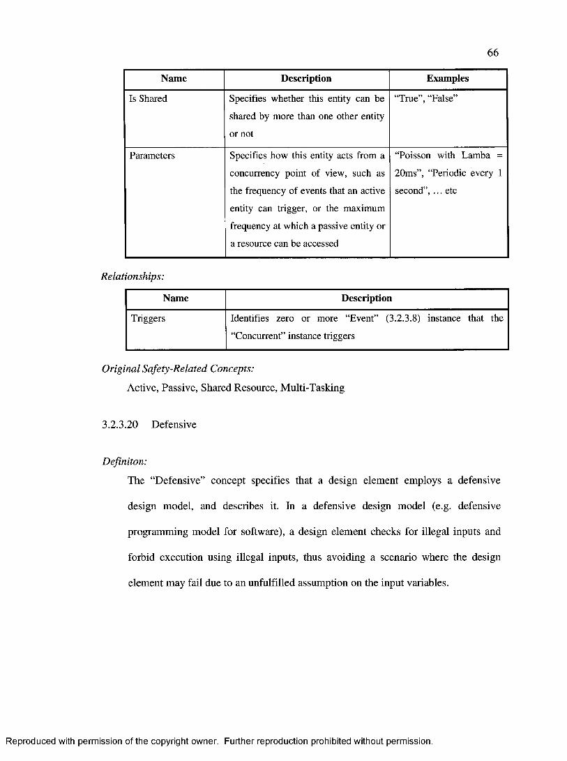
66
Name Description Examples
Is Shared Specifies whether this entity can be
shared by more than one other entity
or not
“True”, “False”
Parameters Specifies how this entity acts from a
concurrency point of view, such as
the frequency of events that an active
entity can trigger, or the maximum
frequency at which a passive entity or
a resource can be accessed
“Poisson with Lamba =
20ms”, “Periodic every 1
second”, ... etc
Relationships:
Name Description
Triggers Identifies zero or more “Event” (3.2.3.8) instance that the
“Concurrent” instance triggers
Original Safety-Related Concepts:
Active, Passive, Shared Resource, Multi-Tasking
3.2.3.20 Defensive
Definiton:
The “Defensive” concept specifies that a design element employs a defensive
design model, and describes it. In a defensive design model (e.g. defensive
programming model for software), a design element checks for illegal inputs and
forbid execution using illegal inputs, thus avoiding a scenario where the design
element may fail due to an unfulfilled assumption on the input variables.
Reproduced with permission of the copyright owner. Further reproduction prohibited without permission.
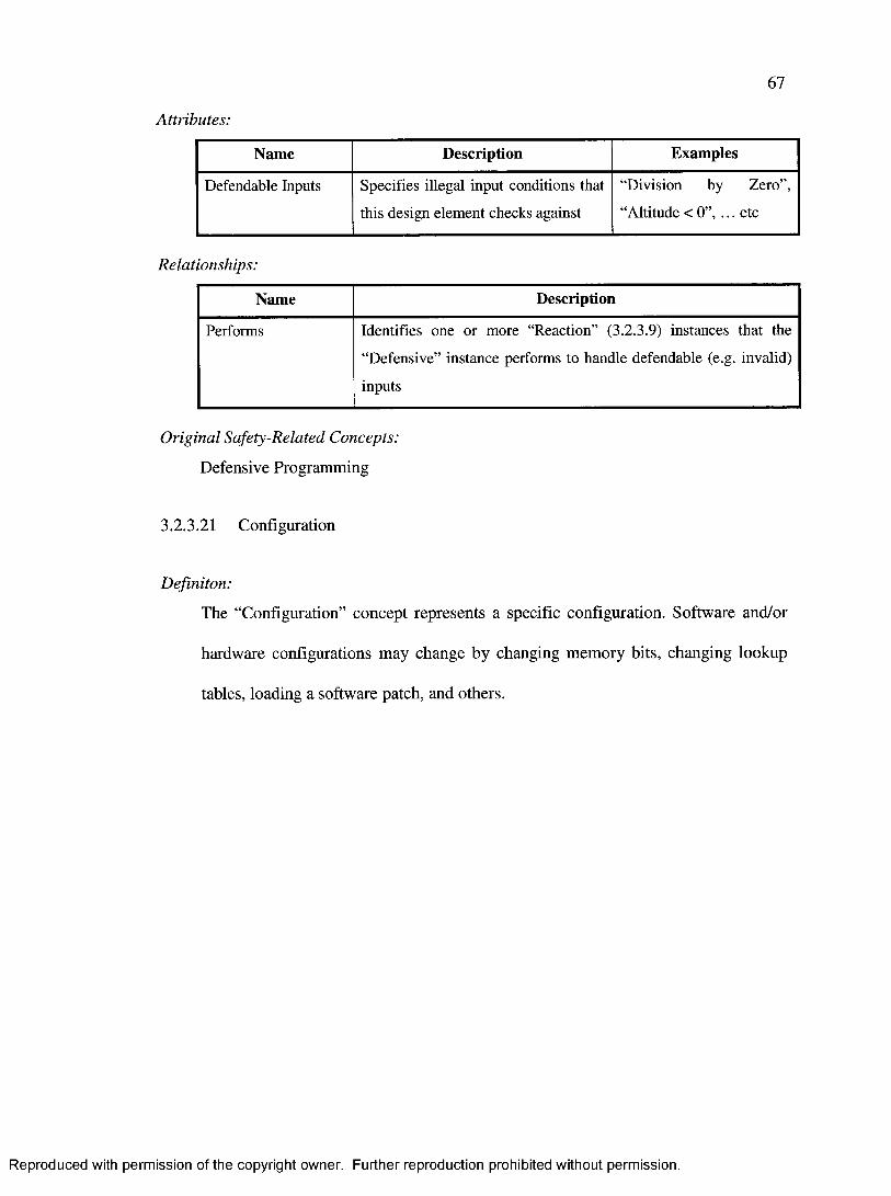
67
Attributes:
Name Description Examples
Defendable Inputs Specifies illegal input conditions that
this design element checks against
“Division by Zero”,
“Altitude < 0”, ... etc
Relationships:
Name Description
Performs Identifies one or more “Reaction” (3.2.3.9) instances that the
“Defensive” instance performs to handle defendable (e.g. invalid)
inputs
Original Safety-Related Concepts:
Defensive Programming
3.2.3.21 Configuration
Definiton:
The “Configuration” concept represents a specific configuration. Software and/or
hardware configurations may change by changing memory bits, changing lookup
tables, loading a software patch, and others.
Reproduced with permission of the copyright owner. Further reproduction prohibited without permission.

68
Attributes:
Name Description Examples
ID Uniquely identifies a specific
software configuration
For a user interface
software that can provide
interface in many
languages based on a
string lookup table:
“English Interface”,
“French Interface”,
“German Interface”, ...
etc
Relationships:
None
Original Safety-Related Concepts:
Configuration
3.2.3.22 Configurable
Definiton:
The “Configurable” concept identifies a design element that can be configured or
altered to produce a different configuration (3.2.3.21) or behaviour. Such change is
generally performed by the user or buyer of the software, not the by vendor or its
development team.
Attributes:
Name Description Examples
Kind The kind of this configurable design
element
“Memory Bits”, “Lookup
Tables”, ...etc
Reproduced with permission of the copyright owner. Further reproduction prohibited without permission.
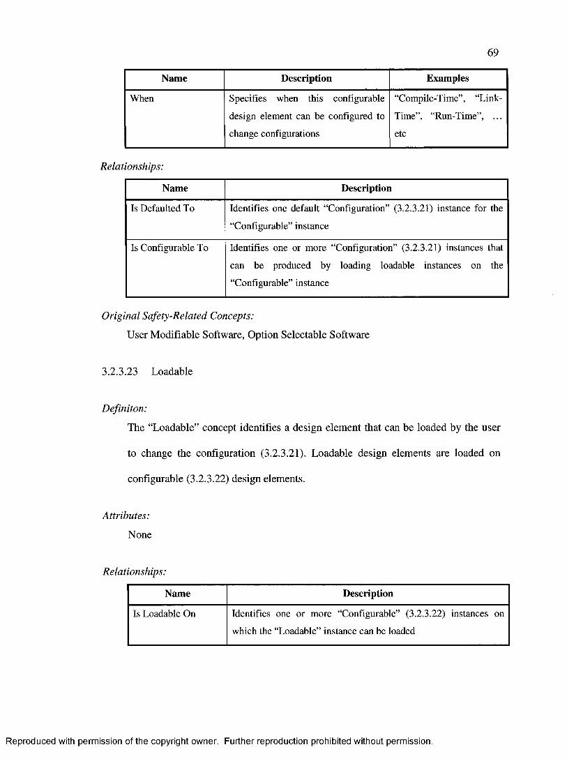
69
Name Description Examples
When Specifies when this configurable
design element can be configured to
change configurations
“Compile-Time”, “Link-
Time”, “Run-Time”, ...
etc
Relationships:
Name Description
Is Defaulted To Identifies one default “Configuration” (3.2.3.21) instance for the
“Configurable” instance
Is Configurable To Identifies one or more “Configuration” (3.2.3.21) instances that
can be produced by loading loadable instances on the
“Configurable” instance
Original Safety-Related Concepts:
User Modifiable Software, Option Selectable Software
3.2.3.23 Loadable
Definiton:
The “Loadable” concept identifies a design element that can be loaded by the user
to change the configuration (3.2.3.21). Loadable design elements are loaded on
configurable (3.2.3.22) design elements.
Attributes:
None
Relationships:
Name Description
Is Loadable On Identifies one or more “Configurable” (3.2.3.22) instances on
which the “Loadable” instance can be loaded
Reproduced with permission of the copyright owner. Further reproduction prohibited without permission.

70
Name Description
Requires Identifies zero or more “Configuration” (3.2.3.21) instances in
which the “Loadable” instance can be loaded
Produces Identifies one or more “Configuration” (3.2.3.21) instances that
result by loading the “Loadable” instance
Original Safety-Related Concepts:
Field Loadable Software, Software Patch
3.2.3.24 Configurator
Definiton:
The “Configurator” concept identifies a design element that can configure
configurable (3.2.3.22) design elements to change the configuration (3.2.3.21),
possibly by loading loadable (3.2.3.23) design elements.
Attributes:
None
Relationships:
Name Description
Configures Identifies one or more “Configurable” (3.2.3.22) instances that can
be configured by the “Configurator” instance
Loads Identifies one or more “Loadable” (3.2.3.23) instances that can be
loaded by a “Configurator” on configurable instances
Original Safety-Related Concepts:
Loader
Reproduced with permission of the copyright owner. Further reproduction prohibited without permission.

3.2.3.25 Replicated
71
Definiton:
The “Replicated” concept identifies a design element that participates in a
replication group (3.2.3.27), such as multiple-version dissimilar software, and
whose output is evaluated by a comparator (3.2.3.26).
Attributes:
Name Description Examples
ID Specifies a unique identifier for this
entity within its replication group
“Filter Version 1”, “Filter
Version 2”, “Filter
Version 3”, ... etc
Relationships:
None
Original Safety-Related Concepts:
Multiple-Version Dissimilar Software, Software Redundancy
3.2.3.26 Comparator
Definiton:
The “Comparator” concept identifies a design element that analyzes outputs of
replicated (3.2.3.25) design elements and determines the formal output of the
replication group (3.2.3.27).
Reproduced with permission of the copyright owner. Further reproduction prohibited without permission.
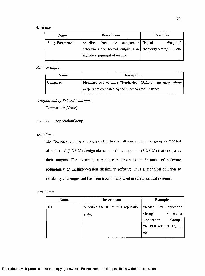
72
Attributes:
Name Description Examples
Policy Parameters Specifies how the comparator
determines the formal output. Can
include assignment of weights
“Equal Weights”,
“Majority Voting”, ... etc
Relationships:
Name Description
Compares Identifies two or more “Replicated” (3.2.3.25) instances whose
outputs are compared by the “Comparator” instance
Original Safety-Related Concepts:
Comparator (Voter)
3.2.3.27 ReplicationGroup
Definiton:
The “ReplicationGroup” concept identifies a software replication group composed
of replicated (3.2.3.25) design elements and a comparator (3.2.3.26) that compares
their outputs. For example, a replication group is an instance of software
redundancy or multiple-version dissimilar software. It is a technical solution to
reliability challenges and has been traditionally used in safety-critical systems.
Attributes:
Name Description Examples
ID Specifies the ID of this replication
group
“Radar Filter Replication
Group”, “Controller
Replication Group”,
“REPLICATION 1”, ...
etc
Reproduced with permission of the copyright owner. Further reproduction prohibited without permission.

73
Relationships:
Name Description
Owns (with
Comparator)
Identifies one “Comparator” (3.2.3.26) instance that belongs to
this “ReplicationGroup” instance
Owns (with
Replicated)
Identifies two or more “Replicated” (3.2.3.25) instances that
belong to this “ReplicationGroup” instance
Original Safety-Related Concepts:
Multiple-Version Dissimilar Software, Software Redundancy
3.2.4 Providing Traceability
The refined concepts and their conceptual model satisfy all the traceabilty requirements
specified in section 2.5.
First, software requirements can be specified using the “Requirement” (3.2.3.1) concept.
Then, software design elements can be traced to software requirements using the
“Rationale” (3.2.3.7) concept. There also exists other concepts that allow for specialized
forms of traceability to requirements, namely the “Deviation” (3.2.3.2), Nature (3.2.3.6),
Partition (3.2.3.11), Implementation Style (3.2.3.4), and Behavioural Style (3.2.3.5)
concepts.
In addition, the conceptual model explicitly identifies the “Event” (3.2.3.8) and
“Reaction” (3.2.3.9) concepts, and establishes traceability links between those two
concepts and the “Handler” concept (3.2.3.12). Furthermore, it requires reactions to be
traceable to events through the “Is Consequence O f’ relationship.
Reproduced with permission of the copyright owner. Further reproduction prohibited without permission.

74
It is important to note that, while the traceability described above and in section 2.5 are
commonly needed for developing software, this conceptual model satisfy many more
traceability requirements than those. In fact, the “Rationale” (3.2.3.7) concept is a “one-
size-fits-all” traceability concept that can be used to trace any model element to any other
model element or requirement. For example, the “Rationale” (3.2.3.7) concept allows
traceability links from safety-critical design elements to requirements, from subsystems
to requirements, and from classes to subsystems
3.3 Information Requirements
Section 3.1 identified detailed safety-related concepts as they appear in the airworthiness
standard, which were refined in section 3.2. Therefore, a UML profile useful for safety
purposes should be able to model at least this information. In other words, the refined
concepts are central to defining information requirements for the definition of a UML
profile, and one can transform every concept into an information requirement.
However, the information requirements we present below are defined at a level lower
than the refined concept and, therefore, a refined concept may correspond to more than
one information requirements. This is done so in order to break down concepts that
capture many details and recognize the fact that existing profiles may only satisfy parts of
a concept. For example, the “Reaction” concept and its “Consequence O f’ attribute can
be considered a single concept, but they capture two different pieces of information.
Therefore, they are represented as two different information requirements (IREQ 22 and
IREQ 23 below) to recognize the fact that a UML profile can meet only one of those two
requirements (and therefore partially, but not entirely, be able to model the concept).
Reproduced with permission of the copyright owner. Further reproduction prohibited without permission.

75
Moreover, there are terms that are useful from a modeling prespective but that are not
really safety-related concepts. They were not mentioned in section 3.2 because they are
not concepts. Nevertheless, they help the modeler specify safety-related information in
the model. Their information requirements are IREQ 1 - IREQ 8 (see below). It is
common in UML profiles to provide stereotypes for such cases (see OMG UML profiles
such as [5] and [6] for examples). Examples of those concepts include: Safety Context,
which is used to provide high-level information about the safety of the software;
Performance Context, which is used to provide high-level information about the
performance aspects of the software.
The information requirements we derived from the concepts presented in section 3.2.3
are:
IREQ 1 The profile shall be able to identify a safety-related software context.
IREQ 2 The profile shall be able to identify a reliability-related software context.
IREQ 3 The profile shall be able to identify an integrity-related software context.
IREQ 4 The profile shall be able to identify a performance-related software
context.
IREQ 5 The profile shall be able to identify a concurrency-related software
context.
IREQ 6 The profile shall be able to identify a certification-related software
context.
IREQ 7 The profile shall be able to identify a configuration-related software
context.
IREQ 8 The profile shall be able to identify a design-related software context.
IREQ 9 The profile shall be able to specify software requirements, including the
kind of the requirements such as safety, certification, and derived.
IREQ 10 The profile shall be able to relate software requirements to other
requirements.
Reproduced with permission of the copyright owner. Further reproduction prohibited without permission.

IREQ 11
IREQ 12
IREQ 13
IREQ 14
IREQ 15
IREQ 16
IREQ 17
IREQ 18
IREQ 19
IREQ 20
IREQ 21
IREQ 22
IREQ 23
IREQ 24
76
The profile shall be able to model a software model deviation from a plan,
requirement, or a standard.
The profile shall be able to model specific software implementation styles
of interest to airworthiness-related software such as recursion, dynamic
memory, compacted expressions, and data aliases.
The profile shall be able to model time-related software such as filters.
The profile shall be able to model state-related software such as state
machines.
The profile shall be able to model COTS software, including the rationale
for using it.
The profile shall be able to model previously-developed software,
including the rationale for using it.
The profile shall be able to model software that has deactivated code and
the rationale for including the deactivated code in the design.
The profile shall be able to provide traceability by relating model
elements to other elements that caused related design decisions, such as
relating a software comparator to a requirement element that says that a
software comparator shall be used for multiple-version dissimilar
software.
The profile shall provide the capability to specify a reference or
explanation for a modeled traceability, possibly referring to non-model
elements or documents.
The profile shall be able to model software events.
The profile shall be able to specify how a particular software event affects
the level of safety.
The profile shall be able to model software reactions, or responses, to
software events.
The profile shall be able to specify which reactions, or responses, occur
for which events.
The profile shall be able to specify how a particular software reaction, or
response, affects the level of safety.
Reproduced with permission of the copyright owner. Further reproduction prohibited without permission.
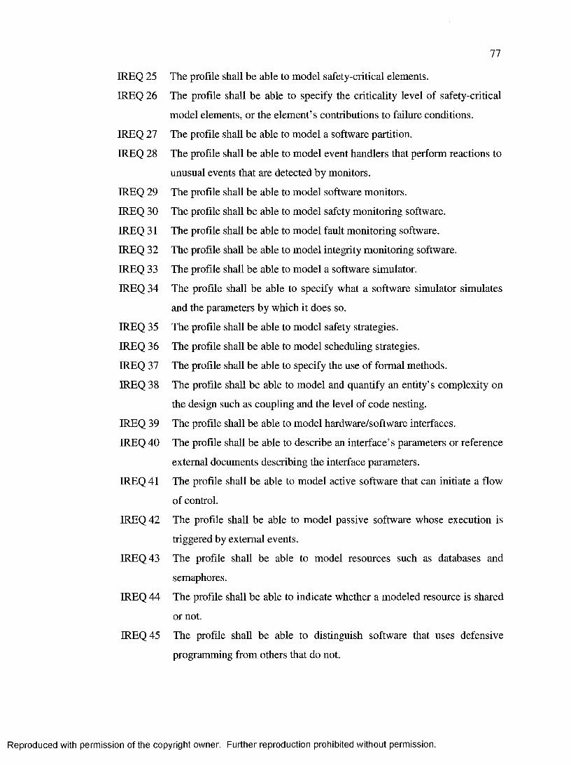
IREQ 25
IREQ 26
IREQ 27
IREQ 28
IREQ 29
IREQ 30
IREQ 31
IREQ 32
IREQ 33
IREQ 34
IREQ 35
IREQ 36
IREQ 37
IREQ 38
IREQ 39
IREQ 40
IREQ 41
IREQ 42
IREQ 43
IREQ 44
IREQ 45
77
The profile shall be able to model safety-critical elements.
The profile shall be able to specify the criticality level of safety-critical
model elements, or the element’s contributions to failure conditions.
The profile shall be able to model a software partition.
The profile shall be able to model event handlers that perform reactions to
unusual events that are detected by monitors.
The profile shall be able to model software monitors.
The profile shall be able to model safety monitoring software.
The profile shall be able to model fault monitoring software.
The profile shall be able to model integrity monitoring software.
The profile shall be able to model a software simulator.
The profile shall be able to specify what a software simulator simulates
and the parameters by which it does so.
The profile shall be able to model safety strategies.
The profile shall be able to model scheduling strategies.
The profile shall be able to specify the use of formal methods.
The profile shall be able to model and quantify an entity’s complexity on
the design such as coupling and the level of code nesting.
The profile shall be able to model hardware/software interfaces.
The profile shall be able to describe an interface’s parameters or reference
external documents describing the interface parameters.
The profile shall be able to model active software that can initiate a flow
of control.
The profile shall be able to model passive software whose execution is
triggered by external events.
The profile shall be able to model resources such as databases and
semaphores.
The profile shall be able to indicate whether a modeled resource is shared
or not.
The profile shall be able to distinguish software that uses defensive
programming from others that do not.
Reproduced with permission of the copyright owner. Further reproduction prohibited without permission.

78
IREQ 46 The profile shall be able to describe the defensive programming
parameters of software developed using defensive programming methods.
IREQ 47 The profile shall be able to model software elements whose behaviour can
be modified by the user (e.g. by changing memory bits or loading look-up
tables).
IREQ 48 The profile shall be able to specify what can be modified about
modifiable software elements (e.g. is it a set of memory bits? A lookup
table?).
IREQ 49 The profile shall be able to specify when a modifiable software element
can be modified, such as at compile-time or run-time.
IREQ 50 The profile shall be able to model software that can be loaded into a
system (e.g. software patch) to result in a different software configuration.
IREQ 51 The profile shall be able to model software that the user uses to change
the software configuration (e.g. software used to change a memory bit or
load a lookup table).
IREQ 52 The profile shall be able to model multiple-version dissimilar software.
IREQ 53 The profile shall be able to model software comparators, or voters, for
multiple version dissimilar software
IREQ 54 The profile shall be able to specify the voting policy parameters for
software comparators, or voters.
The requirements traceability matrix in Table 3 describes how the information
requirements trace back to the original high-level requirements presented in section 2.6.3.
This explains how the original-high level requirements are met by a UML profile meeting
the information requirements. If a “Yes” exists in a particular cell, this means that the
information requirement identified by its row traces back to the high-level requirement
identified by its column. Each information requirement may trace back to more than one
high-level requirement. As the table illustrates, there is an n-to-n relationship between
high-level requirements and information requirements.
Reproduced with permission of the copyright owner. Further reproduction prohibited without permission.

79
The requirements traceability matrix answers the following question: Which information
requirements (IREQ) are required in order to meet a particular high-level requirement
(REQ)? Conversly, it can also be used to answer the following question: For a particular
information requirement (IREQ), which high-level requirements (REQ) does it help
meet? Therefore, it is useful if the reader is interested in knowing additional details about
how a particular profile meets the original requirements (REQ). Therefore, all the
information requirements trace to both the safety-related concepts, which form the basis
for the information requirements, and are justified by the high-level requirements.
The rest of this document focuses on the information requirements (IREQ) rather than the
high-level requirements (REQ) because they are easier to use for assessing UML profiles.
Furthermore, information requirements are the true requirements that the profile must
meet because they specify the particular information that must be modeled in UML
models.
Reproduced with permission of the copyright owner. Further reproduction prohibited without permission.

80
REQ 1 REQ 2 REQ 3 REQ 4 REQ 5 REQ 6 REQ 7 TotalIREQ 1 Yes Yes Yes 3IREQ 2 Yes Yes Yes 3IREQ 3 Yes Yes Yes 3IREQ 4 Yes Yes Yes 3IREQ 5 Yes Yes 2IREQ 6 Yes Yes 2IREQ 7 Yes Yes 2IREQ 8 Yes Yes 2IREQ 9 Yes Yes Yes Yes Yes 5
IREQ 10 Yes Yes Yes Yes Yes 5IREQ 11 Yes Yes Yes Yes 4IREQ 12 Yes Yes Yes Yes 4IREQ 13 Yes Yes Yes 3IREQ 14 Yes Yes Yes 3IREQ 15 Yes Yes Yes Yes Yes 5IREQ 16 Yes Yes Yes Yes Yes 5IREQ 17 Yes Yes Yes Yes 4IREQ 18 Yes Yes Yes 3IREQ 19 Yes Yes Yes Yes 4IREQ 20 Yes Yes 2IREQ 21 Yes Yes Yes Yes 4IREQ 22 Yes Yes Yes 3IREQ 23 Yes Yes Yes 3IREQ 24 Yes Yes Yes Yes Yes 5IREQ 25 Yes Yes - Yes 3IREQ 26 Yes Yes Yes Yes 4IREQ 27 Yes Yes Yes 3IREQ 28 Yes Yes Yes 3IREQ 29 Yes Yes Yes 3IREQ 30 Yes Yes Yes Yes 4IREQ 31 Yes Yes Yes Yes 4IREQ 32 Yes Yes Yes 3IREQ 33 Yes Yes 2IREQ 34 Yes Yes 2IREQ 35 Yes Yes Yes Yes 4IREQ 36 Yes Yes Yes 3IREQ 37 Yes Yes 2IREQ 38 Yes Yes 2IREQ 39 Yes Yes 2IREQ 40 Yes Yes 2IREQ 41 Yes Yes 2IREQ 42 Yes Yes 2IREQ 43 Yes Yes 2IREQ 44 Yes Yes 2IREQ 45 Yes Yes Yes 3IREQ 46 Yes Yes Yes 3IREQ 47 Yes Yes Yes Yes 4IREQ 48 Yes Yes Yes Yes 4IREQ 49 Yes Yes Yes 3IREQ 50 Yes Yes Yes 3IREQ 51 Yes Yes Yes 3IREQ 52 Yes .. Yes Yes | 3
Reproduced with permission of the copyright owner. Further reproduction prohibited without permission.

81
REQ 1 REQ 2 REQ 3 REQ 4 REQ 5 REQ 6 REQ 7 TotalIREQ 53 Yes Yes Yes 3IREQ 54 Yes Yes 2
Total 54 8 18 33 18 34 2 167
Table 3: Tracing information requirements to the original high-level requirements.
Reproduced with permission of the copyright owner. Further reproduction prohibited without permission.

82
4 EXISTING UML PROFILES
This section introduces existing UML profiles and approaches and evaluates each one of
them with respect to the information requirements identified in section 3.3. This is
required to determine whether a suitable profile already exists or not, which would
determine whether an existing profile should be extended (if necessary) or a completely
new profile should be defined. Details of the evaluations are reported in Appendix F and
summarized in the following sections.
4.1 Quality of Service and Fault Tolerance OMG Profile
OMG released a profile to model Quality of Service (QoS) for high-quality and Fault-
Tolerant (FT) systems. The profile, presented in [5], includes frameworks to describe
quality of service, risk assessment, and fault tolerance.
The framework to describe quality of service includes mechanisms to describe generic
quality of service driven from quality-based requirements. It is not specific to any kind of
quality of service, such as safety. Its mechanisms focus on characteristics, constraints,
and levels of quality of service. The risk assessment framework includes support for
model-based risk assessment. It provides mechanisms for modeling risk contexts,
stakeholders, assets, strengths, weaknesses, opportunities and threats, unwanted incidents,
risk quantification, and risk mitigation and treatments. The fault tolerance framework
includes mechanisms for describing fault-tolerant software architectures in general as a
technical solution to reliability requirements. It focuses on modeling software
redundancy, or software replication.
Reproduced with permission of the copyright owner. Further reproduction prohibited without permission.

83
Table 18 in Appendix F presents an analysis of the profile with respect to each of the
information requirements described in section 3.3. The table concludes that this profile is
not adequate for extension to meet the information requirements since only 17 of the
information requirements (out of 54) are fulfilled.
4.2 Schedulability, Performance, and Time OMG Profile
OMG released a profile, the Schedulability, Performance, and Time (SPT) profile, which
provides mechanisms to model concepts of importance to real-time systems. Real-time
systems are those where there exist timing requirements on when the responses to events
occur. Soft real-time systems are those were late responses may be acceptable if they are
not within a specified range, whereas hard real-time systems are those where late
responses are unacceptable and may be fatal [6]. The profile, presented in [6], includes
frameworks to model resources, time, concurrency, schedulability, performance, and
CORBA schedulability properties. Using it allows developers to perform performance
analysis of the model.
The resource modeling framework includes mechanisms to model resources, components
that acquire and release them, and their deployment on hosts. The time modeling
framework includes mechanisms to model clocks, timers, timeouts, and actions that are
applied on them such as delays, interrupts, events, pause, reset, start, and stop. The
concurrency modeling framework includes mechanisms to model synchronous and
asynchronous actions, and event queues for immediate and deferred event processing.
The schedulability analysis framework includes mechanism to model actions, engines,
responses, scheduling resources, triggers, action schedulers, and scheduling hosts. The
Reproduced with permission of the copyright owner. Further reproduction prohibited without permission.

84
performance analysis framework includes mechanism to model performance contexts,
open and closed workloads, and steps. The CORBA schedulability framework includes
mechanisms to model CORBA channels, connections, clients, servers, and Object
Resource Brokers (ORBs).
Table 19 in Appendix F presents an analysis of the profile with respect to each of the
information requirements described in section 3.3. The table concludes that this profile is
not adequate for extension to meet the information requirements since only 6 of the
information requirements (out of 54) are fulfilled. The profile does not meet many of the
information requirements because it does not cover safety and reliabity topics.
4.3 HIDOORS Profile
The High Integrity Distributed Object-Oriented Real-Time Systems (HIDOORS) was a
joint research project by several European companies and research institutions. One of
the goals of HIDOORS was to introduce mechanisms for modeling safety-critical and
embedded real-time applications. Those mechanisms were required to be compliant with
OMG’s SPT profile (see section 4.2), provide mechanisms for modeling the Rate
Monotonic Analysis (RMA) scheduling strategy, and provide specific concepts relating
to inter-task communication. The researchers involved in this project felt that UML’s
SPT profile was too general and too fundamental to provide mechanisms for specifying
RMA and some inter-task communication concepts [26]. The profile therefore specializes
some SPT concepts such as triggers, actions, resources, and scheduling jobs.
Furthermore, it provides mechanisms to model inter-task communication styles such as
buffers, black boards, and events.
Reproduced with permission of the copyright owner. Further reproduction prohibited without permission.

85
Table 20 in Appendix F presents an analysis of the profile with respect to each of the
information requirements described in section 3.3. The table concludes that this profile is
not adequate for extension to meet the information requirements since only 6 of the
information requirements (out of 54) are fulfilled. The profile included only few
stereotypes so it does not meet most of the information requirements. In fact, it did not
meet any information requirements that were not already met by the SPT profile.
4.4 Effects of Message Loss, Delay, and Corruption
Jan Jiirjens presented a UML profile in [27] that aimes at addressing safety issues from a
fault-tolerant point of view. Jiirjens argued that safety goals are often expressed
quantitatively via the maximum failure rate, and then presented some possible failures
that served as the basis of the proposed UML profile. Thus, his profile assumes that those
failures are based on the concept of transmitting messages on links and between nodes.
The profile included mechanisms to model risks, crashes, guarantees, redundancy, safe
links, safe dependencies, safety critical elements, safe behaviours, containment, and error
handling.
Table 21 in Appendix F presents an analysis of the profile with respect to each of the
information requirements described in section 3.3. The table concludes that this profile is
not adequate for extension to meet the information requirements since only 7 of the
information requirements (out of 54) are fulfilled. In fact, it does not meet many of the
information requirements because assuming the airworthiness standard does not make the
assumption that unsafe states result from failures of transmitting messages because safety
is a bigger issue than that.
Reproduced with permission of the copyright owner. Further reproduction prohibited without permission.

86
4.5 Patterns for Reliability and Safety
Hansen and Gullesen presented in [28] a series of UML patterns that can be used to
model some aspects of safety-critical systems. They presented patterns for modeling
safety quality of service, software diversity and voting, partial diversity with built-in
diagnostic or monitoring, “safe” communication protocols, and some other topics such as
testing, hazard analysis and quality development. Their work was driven by the IEC
61508 standard in [24]. They have therefore used the concept of Safety Integrity Level
(SIL), which is similar to the concept of software level presented in the airworthiness
standard [4]. The patterns include mechanisms to model the SIL levels, and other patterns
that could be used to explicitly model, in use cases, redundancy, monitoring, and voting
based on multiple output comparisons.
Table 22 in Appendix F presents an analysis of the profile with respect to each of the
information requirements described in section 3.3. The table concludes that the patterns
presented in this paper are not adequate for extension to meet the information
requirements since only 1 of the information requirements (out of 54) are fulfilled. The
patterns mostly focus on reliability and software replication issues, whereas the
information requirements cover a bigger concern.
4.6 Summary
Table 23 in Appendix F summarizes how each of those existing UML profiles scores
with respect to addressing the information requirements identified in section 3.3. Each
Reproduced with permission of the copyright owner. Further reproduction prohibited without permission.

87
profile’s score is calculated based on how many information requirements it meets.
Therefore, the maximum score is 54 (100%).
As it can be noticed from previous sections, which results are summarized in Table 23,
none of the existing profiles that were evaluated achieves more than 31% of the
maximum score. In fact, all of the profiles combined only meet 44% of the information
requirements.
The two OMG profiles are useful, but only within their intended domain. The OMG QoS
and FT profile is suitable for modeling fault tolerance and software redundancy. The
OMG SPT profile is suitable for modeling schedulability, performance, and concurrency
concepts. However, it was evident in section 3 that safety and airworthiness are
dependent on many domains. Therefore, those two OMG profiles would be
complimentary, but not complete enough. It should also be noticed that the SPT profile
included more details than the QoS and FT profile, but it was centred on domains that are
somehow less important to safety (resources, time, concurrency, performance, and
schedulability) than those covered by the QoS and FT profile (quality of service, risk
assessment, fault tolerance).
Furthermore, the profile for the “effects of messages on safety” introduces some useful
stereotypes such as « s a f e behaviour» , « g u a ra n te e » , « c r i t ic a l» ,
« co n ta in m en t» an d « re d u n d a n c y » . However, some of them are too general to be
effective, such as « c r i t i c a l» which does not tell us the criticality level (e.g.
airworthiness level) of the software. Neverthless, it meets some information requirements
that are not met by the 2 OMG profiles such as the ability to model exception handlers.
Reproduced with permission of the copyright owner. Further reproduction prohibited without permission.

88
The “HIDOORS” profile did not meet any information requirements that were not
already met by the SPT profile.
The “Patterns” paper did not fulfil any information requirements that were not fulfilled
by the other profiles.
Because none of the existing UML profiles and patterns comes close to fulfilling the
information requirements, a new UML profile is proposed instead of extending an
existing one. This has the advantage that the resultant profile will be coherent and
specifically designed to meet the information requirements instead of “patching” an
existing profile that was originally designed for some other purpose.
Reproduced with permission of the copyright owner. Further reproduction prohibited without permission.
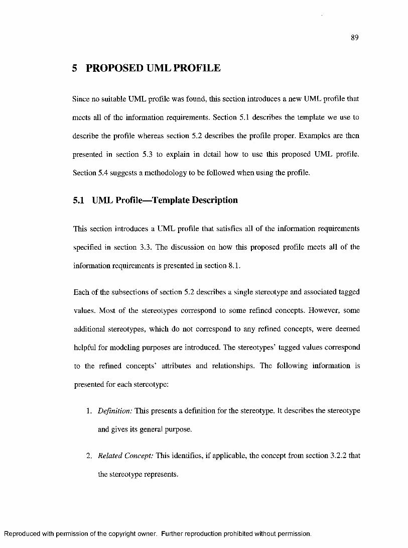
89
5 PROPOSED UML PROFILE
Since no suitable UML profile was found, this section introduces a new UML profile that
meets all of the information requirements. Section 5.1 describes the template we use to
describe the profile whereas section 5.2 describes the profile proper. Examples are then
presented in section 5.3 to explain in detail how to use this proposed UML profile.
Section 5.4 suggests a methodology to be followed when using the profile.
5.1 UML Profile—Template Description
This section introduces a UML profile that satisfies all of the information requirements
specified in section 3.3. The discussion on how this proposed profile meets all of the
information requirements is presented in section 8.1.
Each of the subsections of section 5.2 describes a single stereotype and associated tagged
values. Most of the stereotypes correspond to some refined concepts. However, some
additional stereotypes, which do not correspond to any refined concepts, were deemed
helpful for modeling purposes are introduced. The stereotypes’ tagged values correspond
to the refined concepts’ attributes and relationships. The following information is
presented for each stereotype:
1. Definition: This presents a definition for the stereotype. It describes the stereotype
and gives its general purpose.
2. Related Concept: This identifies, if applicable, the concept from section 3.2.2 that
the stereotype represents.
Reproduced with permission of the copyright owner. Further reproduction prohibited without permission.

90
3. Base Classes: This lists the UML meta-classes on which the stereotype may be
applied. The explanation on how and why the stereotype may be applied on each
meta-class is also presented. This does not identify meta-classes on which the
stereotype may not be applied to allow future extenstions of this profile to be
backwards compatible. This is because future extension may permit the
application of the stereotypes on meta-classes that are not explicit here. This is
necessary because extending UML, such as in the form of UML profiles, permits
adding new rules but does not allow removing existing rules.
4. Tags: This lists the tags that the stereotype has. For each tag, the type,
multiplicity, and a description is presented.
The base classes of each stereotype are presented in a table. For example, the base classes
of the « S a fe ty C ritic a l» (5.2.17) stereotype are presented as follows:
Base Class Usage RationaleClass To indicate that the class is safety-critical (3.2.3.10) and specify
its safety (e.g. airworthiness) level
Operation To indicate that invoking the operation is safety-critical (3.2.3.10)
and specify its safety (e.g. airworthiness) level
Relationship To indicate that the relationship is safety-critical (3.2.3.10) and
specify its safety (e.g. airworthiness) level
The first column lists the UML meta-classes on whose instances the stereotype can be
applied. The UML classes are specified as defined in the UML meta-model in [29] and
[30]. This profile uses only the following base classes in the first column:
Reproduced with permission of the copyright owner. Further reproduction prohibited without permission.
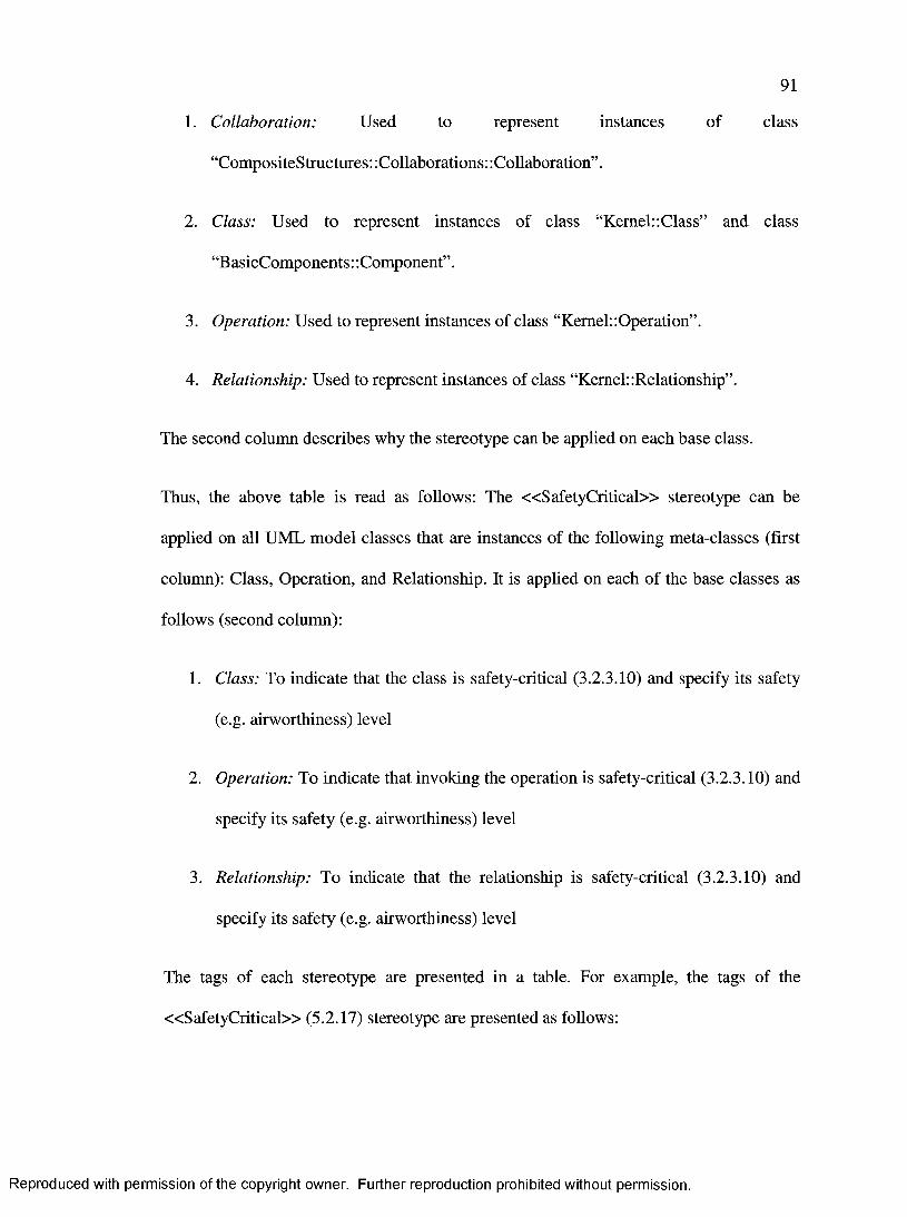
91
1. Collaboration: Used to represent instances of class
“CompositeStructures: :Collaborations:: Collaboration”.
2. Class: Used to represent instances of class “Kernel:-.Class” and class
“BasicComponents: :Component” .
3. Operation: Used to represent instances of class “Kernel::Operation”.
4. Relationship: Used to represent instances of class “Kernel: Relationship”.
The second column describes why the stereotype can be applied on each base class.
Thus, the above table is read as follows: The « S a fe ty C ritic a l» stereotype can be
applied on all UML model classes that are instances of the following meta-classes (first
column): Class, Operation, and Relationship. It is applied on each of the base classes as
follows (second column):
1. Class: To indicate that the class is safety-critical (3.2.3.10) and specify its safety
(e.g. airworthiness) level
2. Operation: To indicate that invoking the operation is safety-critical (3.2.3.10) and
specify its safety (e.g. airworthiness) level
3. Relationship: To indicate that the relationship is safety-critical (3.2.3.10) and
specify its safety (e.g. airworthiness) level
The tags of each stereotype are presented in a table. For example, the tags of the
« S a fe ty C ritic a l» (5.2.17) stereotype are presented as follows:
Reproduced with permission of the copyright owner. Further reproduction prohibited without permission.

92
Name Type Multiplicity DescriptionCriticalityLevel Enumeration [0..1] See attribute: Criticality Level
ConfidenceLevel Enumeration [0..1] See attribute: Confidence
Level
TriggeredEvent Reference to a
model element
stereotyped
« E v e n t»
(5.2.15) (or its
subclass
« R eac tio n »
(5.2.16))
[0..*] See relationship: Triggers
The first column specifies the tag name, the second column specifies the type of the tag,
the third column specifies its multiplicity, and the fourth column provides a description of
the tag. In most cases, the fourth column will refer the reader to an attribute or a
relationship of the related concept.
This example tells us that this stereotype has the following tags and they are described as
follows:
1. The “CriticalityLevel” tag (first column) of the « S a fe ty C ritic a l» stereotype is
specified through an enumeration (second column). It can be specified zero or one
time (third column) for each stereotype. Its description is the same as the
“Criticality Level” attribute of the related concept (“Safety Critical” (3.2.3.10)
concept in this case) (fourth column).
2. The “ConfidenceLevel” tag (first column) of the « S a fe ty C ritic a l» stereotype is
specified through an enumeration (second column). It can be specified zero or one
Reproduced with permission of the copyright owner. Further reproduction prohibited without permission.

93
time (third column) for each stereotype. Its description is the same as the
“Confidence Level” attribute of the related concept (“Safety Critical” (3.2.3.10)
concept in this case) (fourth column).
3. The “TriggeredEvent” tag (first column) of the « S a fe ty C ritic a l» stereotype is
specified through a reference to a model element stereotyped with « E v e n t » or
« R e a c t io n » (second column). It can be specified zero or as many times as one
wishes (third column) for each stereotype. Its description is the same as the
“Triggers” relationship of the related concept (“SafetyCritical” (3.2.3.10) concept
in this case) (fourth column).
5.2 Profile Description
5.2.1 « S a fe ty C o n tex t»
Definiton:
The « S a fe ty C o n te x t» stereotype is used to indicate that there is safety-related
information of interest such as information representing the original primarily
safety concepts listed in Appendix C .l.
Related Concept:
None
Base Classes:
Base Class Usage RationaleCollaboration To indicate that the collaboration contains safety information
Tags:
None
Reproduced with permission of the copyright owner. Further reproduction prohibited without permission.

94
5.2.2 «R eliab ilityC on text»
Definiton:
The «R eliab ilityC on tex t» stereotype is used to indicate that there is reliability-
related information of interest such as information representing the original
primarily reliability concepts listed in Appendix C.2. In one specific usage, it could
also be used to describe or identify a specific replication group (see related
concept).
Related Concept:
ReplicationGroup (3.2.3.27)
Base Classes:
Base Class Usage RationaleCollaboration To indicate that the collaboration contains reliability information,
or to identify a particular replication group (3.2.3.27) composed
of replicated (3.2.3.25) design elements and a comparator
(3.2.3.26)
Tags:
Name Type Multiplicity Description
ID String [0..1] See attribute: ID
5.2.3 «IntegrityC ontext»
Definiton:
The « In teg rityC on tex t» stereotype is used to indicate that there is safety-related
information of interest such as information representing the original primarily
integrity concepts listed in Appendix C.3.
Reproduced with permission of the copyright owner. Further reproduction prohibited without permission.

95
Related Concept:
None
Base Classes:
Base Class Usage RationaleCollaboration To indicate that the collaboration contains integrity information
Tags:
None
5.2.4 «P erform anceC on text»
Definiton:
The «P erfo rm anceC ontex t» stereotype is used to indicate that there is
performance-related information of interest such as information representing the
original primarily performance concepts listed in Appendix C.4.
Related Concept:
None
Base Classes:
Base Class Usage RationaleCollaboration To indicate that the collaboration contains performance
information
Tags:
None
Reproduced with permission of the copyright owner. Further reproduction prohibited without permission.

96
5.2.5 «C oncurren cyC ontext»
Definiton:
The «C oncurrencyC ontex t» stereotype is used to indicate that there is
concurrency-related information of interest such as information representing the
original primarily concurrency concepts listed in Appendix C.5.
Related Concept:
None
Base Classes:
Base Class Usage RationaleCollaboration To indicate that the collaboration contains concurrency
information
Tags:
None
5.2.6 «C ertificationC on text»
Definiton:
The «C ertifica tionC ontex t» stereotype is used to indicate that there is
certification-related information of interest such as information representing the
original primarily certification concepts listed in Appendix C.6.
Related Concept:
None
Reproduced with permission of the copyright owner. Further reproduction prohibited without permission.

97
Base Classes:
Base Class Usage RationaleCollaboration To indicate that the collaboration contains certification
information
Tags:
None
5.2.7 « D esig n C o n tex t»
Definiton:
The « D esig n C o n tex t» stereotype is used to indicate that there is specific design-
related information of interest such as information representing the original
primarily design concepts listed in Appendix C.7.
Related Concept:
None
Base Classes:
Base Class Usage RationaleCollaboration To indicate that the collaboration contains specific design
information such as design constraints and design decisions
Tags:
None
5.2.8 «C onfigurationC ontext»
Definiton:
The «C onfigurationC ontext» stereotype is used to indicate that there is
configuration-related information of interest such as information representing the
Reproduced with permission of the copyright owner. Further reproduction prohibited without permission.
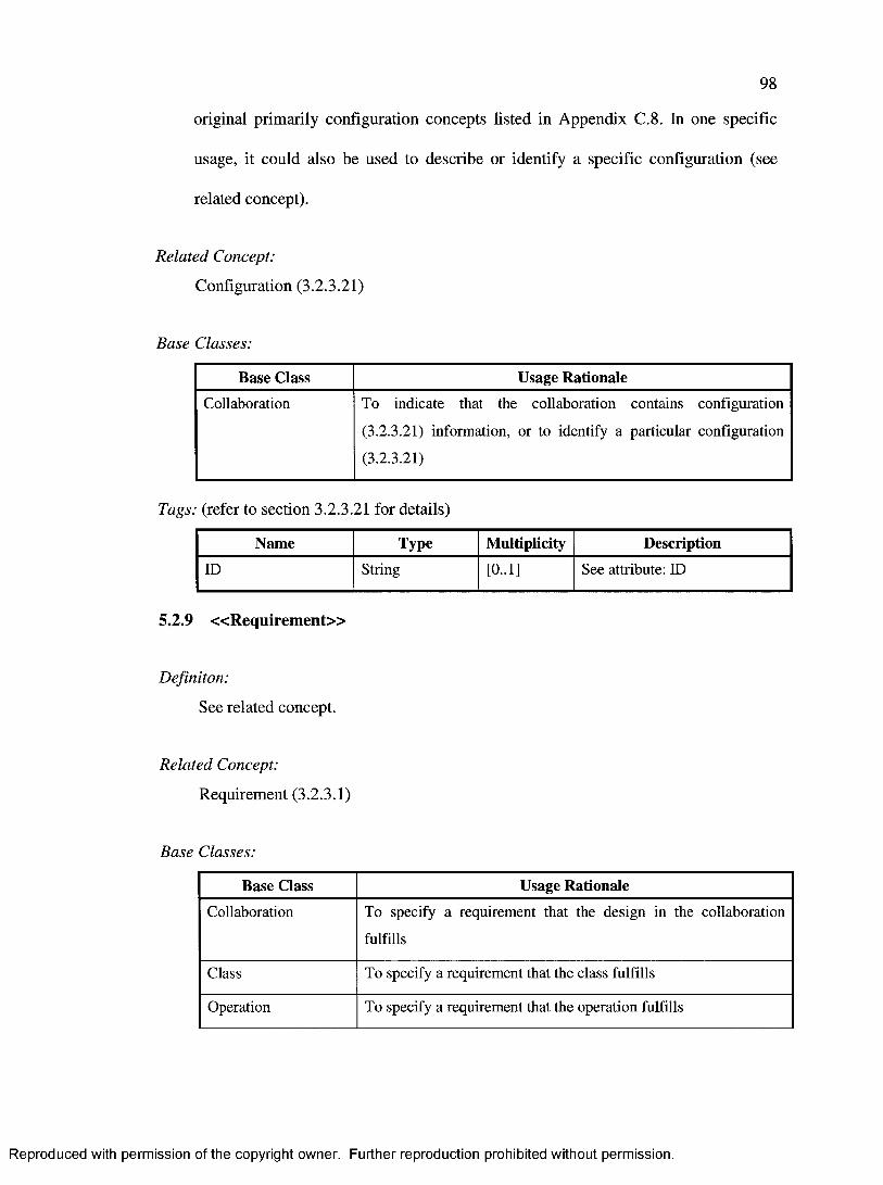
98
original primarily configuration concepts listed in Appendix C.8. In one specific
usage, it could also be used to describe or identify a specific configuration (see
related concept).
Related Concept:
Configuration (3.2.3.21)
Base Classes:
Base Class Usage RationaleCollaboration To indicate that the collaboration contains configuration
(3.2.3.21) information, or to identify a particular configuration
(3.2.3.21)
Tags: (refer to section 3.2.3.21 for details)
Name Type Multiplicity DescriptionID String [0..1] See attribute: ID
5.2.9 « R e q u ir e m e n t»
Definiton:
See related concept.
Related Concept:
Requirement (3.2.3.1)
Base Classes:
Base Class Usage RationaleCollaboration To specify a requirement that the design in the collaboration
fulfills
Class To specify a requirement that the class fulfills
Operation To specify a requirement that the operation fulfills
Reproduced with permission of the copyright owner. Further reproduction prohibited without permission.

99
Base Class Usage Rationale
Relationship To specify a requirement that a relationship fulfills
Tags: (refer to section 3.2.3.1 for details)
Name Type Multiplicity Description
ID String [0..1] See attribute: ID
Kind Enumeration [0..1] See attribute: Kind
Specification Expression [1-1] See attribute: Specification
OfRequirement Reference to a
model element
stereotyped
«R equirem ent»
(5.2.9)
[0..*] See relationship: Is
Requirement Of
5.2.10 « D e v ia t io n »
Definiton:
See related concept.
Related Concept:
Deviation (3.2.3.2)
Base Classes:
Base Class Usage RationaleCollaboration To specify that the collaboration’s design and/or implementation
deviates from a requirement (3.2.3.1), standard, or plan
Class To specify that the class’ design and/or implementation deviates
from a requirement (3.2.3.1), standard, or plan
Operation To specify that the operation’s design and/or implementation
deviates from a requirement (3.2.3.1), standard, or plan
Reproduced with permission of the copyright owner. Further reproduction prohibited without permission.

100
Base Class Usage RationaleRelationship To specify that the relationship’s design and/or implementation
deviates from a requirement (3.2.3.1), standard, or plan
Tags: (refer to section 3.2.3.2 for details)
Name Type Multiplicity DescriptionKind Enumeration [0..1] See attribute: Kind
Reference Reference to a
model element
stereotyped
«R equirem ent»
(5.2.9)
[1..*] See relationship: References
Explanation String [0..*] See attribute: Explanation
5.2.11 «Im plem entationS tyle»
Definiton:
See related concept.
Related Concept:
ImplementationStyle (3.2.3.4)
Base Classes:
Base Class Usage RationaleClass To identify an implementation style (3.2.3.4) (e.g. dynamic
memory, recursive algorithms, ... etc) that is followed in the
implementation of the class
Operation To identify an implementation style (3.2.3.4) (e.g. dynamic
memory, recursive algorithms, ... etc) that is followed in the
implementation of the operation
Reproduced with permission of the copyright owner. Further reproduction prohibited without permission.

101
Tags: (refer to section 3.2.3.4 for details)
Name Type Multiplicity Description
Kind Enumeration [0..1] See attribute: Kind
Parameter Expression [0..*] See attribute: Parameters
Reference Reference to a
model element
stereotyped
«R equirem ent»
(5.2.9), or a String
[0..*] See relationship: References
Explanation String [0.*] See attribute: Explanation
5.2.12 «B eh av iou ra lS ty le»
Definiton:
See related concept.
Related Concept:
BehaviouralStyle (3.2.3.5)
Base Classes:
Base Class Usage RationaleCollaboration To identify a behavioural style (3.2.3.5) (e.g. state-related such as
state machines, ... etc) that is followed in the implementation of
the design specified in the collaboration
Class To identify a behavioural style (3.2.3.5) (e.g. state-related as in
class attributes, time-related as in filters, ... etc) that is followed
in the implementation of the class
Operation To identify a behavioural style (3.2.3.5) (e.g. state-related as in
static operations, time-related as in filters) that is followed in the
implementation of the operation
Reproduced with permission of the copyright owner. Further reproduction prohibited without permission.

102
Tags: (refer to section 3.2.3.5 for details)
Name Type Multiplicity DescriptionKind Enumeration [0..1] See attribute: Kind
Parameter Expression [0..*] See attribute: Parameters
Reference Reference to a
model element
stereotyped
«R equirem ent»
(5.2.9), or a String
[0..*] See relationship: References
Explanation String [0..*] See attribute: Explanation
5.2.13 « N a t u r e »
Definiton:
See related concept.
Related Concept:
Nature (3.2.3.6)
Base Classes:
Base Class Usage RationaleClass To identify the nature (3.2.3.6) (e.g. COTS, previously developed,
deactivated, ... etc) of the class
Operation To identify the nature (3.2.3.6) (e.g. deactivated, ... etc) of the
operation
Tags: (refer to section 3.2.3.6 for details)
Name Type Multiplicity DescriptionKind Enumeration [0..1] See attribute: Kind
Reproduced with permission of the copyright owner. Further reproduction prohibited without permission.

103
Name Type Multiplicity Description
Reference Reference to a
model element
stereotyped
«R equirem ent»
(5.2.9), or a String
[0..*] See relationship: References
Explanation String [0..*] See attribute: Explanation
5.2.14 « R a t io n a le »
Definiton:
See related concept.
Related Concept:
Rationale (3.2.3.7)
Base Classes:
Base Class Usage RationaleCollaboration To explain the rationale (3.2.3.7) or explain the design decisions
for the design specified in the collaboration
Class To explain the rationale (3.2.3.7), explain the design decisions, or
identify the reason for defining and developing the class
Operation To explain the rationale (3.2.3.7), explain the design decisions, or
identify the reason for defining and developing the operation
Relationship To explain the rationale (3.2.3.7), explain the design decisions, or
identify the reason for defining the relationship
Reproduced with permission of the copyright owner. Further reproduction prohibited without permission.

104
Tags: (refer to section 3.2.3.7 for details)
Name Type Multiplicity DescriptionReference Reference to a
model element
stereotyped
«R equirem ent»
(5.2.9), or a String
[1..*] See relationship: References
Explanation String [0..*] See attribute: Explanation
5.2.15 « E v e n t »
Definiton:
See related concept.
Related Concept:
Event (3.2.3.8)
Base Classes:
Base Class Usage RationaleClass To indicate that the class contains information that constitutes and
describes an event (3.2.3.8) of interest
Operation To indicate that invoking the specified operation is an event
(3.2.3.8) of interest, and to further describe the operation’s effect
on safety
Tags: (refer to section 3.2.3.8 for details)
Name Type Multiplicity Description
Kind Enumeration [0..1] See attribute: Kind
When Expression [0..*] See attribute: When
EffectOnSafety Direction Enumeration [0..*] See attribute: Effect On
Safety Direction
Reproduced with permission of the copyright owner. Further reproduction prohibited without permission.

105
Name Type Multiplicity Description
EffectOnSafety V alue Expression [0..*] See attribute: Effect On
Safety Value
EffectOnSafetyContext Expression [0..*] See attribute:
EffectOnSafetyContext
5.2.16 « R e a c t io n »
Definiton:
See related concept.
Related Concept:
Reaction (3.2.3.9)
Base Classes:
Base Class Usage RationaleClass To indicate that the class contains the logic (e.g. hardware or
executable software code) that constitutes and describes a reaction
(3.2.3.9)
Operation To indicate that invoking the specified operation is a reaction
(3.2.3.9) to one or more events (3.2.3.8) of interest, and to further
describe the operation’s effect on safety
Tags: (refer to section 3.2.3.9 for details)
Name Type Multiplicity Description
Kind Enumeration [0..1] See attribute: Kind
Reproduced with permission of the copyright owner. Further reproduction prohibited without permission.

106
Name Type Multiplicity DescriptionConsequenceOf Reference to a
model element
stereotyped
« E v e n t»
(5.2.15) (or its
subclass
«R eac tio n »
(5.2.16))
[1..*] See relationship: Is
Consequence Of
When Expression [0..*] See attribute: When
EffectOnSafetyDirection Enumeration [0..*] See attribute: Effect On
Safety Direction
EffectOnSafety V alue Expression [0..*] See attribute: Effect On
Safety Value
EffectOnSafetyContext Expression [0..*] See attribute:
EffectOnSafetyContext
5.2.17 « S a fe ty C r itica l»
Definiton:
See related concept.
Related Concept:
SafetyCritical (3.2.3.10)
Base Classes:
Base Class Usage RationaleClass To indicate that the class is safety-critical (3.2.3.10) and specify
its safety (e.g. airworthiness) level
Operation To indicate that invoking the operation is safety-critical (3.2.3.10)
and specify its safety (e.g. airworthiness) level
Reproduced with permission of the copyright owner. Further reproduction prohibited without permission.

107
Base Class Usage RationaleRelationship To indicate that the relationship is safety-critical (3.2.3.10) and
specify its safety (e.g. airworthiness) level
Tags: (refer to section 3.2.3.10 for details)
Name Type Multiplicity Description
CriticalityLevel Enumeration [0..1] See attribute: Criticality Level
ConfidenceLevel Enumeration [0..1] See attribute: Confidence
Level
TriggeredEvent Reference to a
model element
stereotyped
« E v e n t»
(5.2.15) (or its
subclass
«R eac tio n »
(5.2.16))
[0..*] See relationship: Triggers
5.2.18 « P a r t it io n »
Definiton:
See related concept.
Related Concept:
Partition (3.2.3.11)
Base Classes:
Base Class Usage RationaleClass To indicate that the class is has been partitioned (3.2.3.11) from
some other (usually more safety-critical (3.2.3.10)) class
Reproduced with permission of the copyright owner. Further reproduction prohibited without permission.

108
Tags: (refer to section 3.2.3.11 for details)
Name Type Multiplicity DescriptionPartitionedFrom Reference to a
class model
element
stereotyped
«SafetyC ritical»
(5.2.17)
[1..*] See relationship: Is
Partitioned From
Reference Reference to a
model element
stereotyped
«R equirem ent»
(5.2.9), or a String
[0..*] See relationship: References
Explanation String [0..*] See attribute: Explanation
5.2.19 « H a n d le r »
Definiton:
See related concept.
Related Concept:
Handler (3.2.3.12)
Base Classes:
Base Class Usage RationaleClass To indicate that the class is an event (3.2.3.8) handler (3.2.3.12)
Reproduced with permission of the copyright owner. Further reproduction prohibited without permission.

109
Tags: (refer to section 3.2.3.12 for details)
Name Type Multiplicity DescriptionHandleableEvent Reference to a
model element
stereotyped
« E v e n t»
(5.2.15) (or its
subclass
«R eac tio n »
(5.2.16))
[1..*] See relationship: Handles
PerformedReaction Reference to a
model element
stereotyped
«R eac tio n »
(5.2.16)
[1..*] See relationship: Performs
5.2.20 « M o n it o r »
Definiton:
See related concept.
Related Concept:
Monitor (3.2.3.13)
Base Classes:
Base Class Usage RationaleClass To indicate that the class is a monitor (3.2.3.13) that monitors
some other class
Tags: (refer to section 3.2.3.13 for details)
Name Type Multiplicity DescriptionKind Enumeration [0..1] See attribute: Kind
Reproduced with permission of the copyright owner. Further reproduction prohibited without permission.

110
Name Type Multiplicity DescriptionMonitoredEntity Reference to a
class model
element
stereotyped
«SafetyCritical»
(5.2.17)
[1..*] See relationship: Monitors
DetectableEvent Reference to a
model element
stereotyped
« E v e n t»
(5.2.15) (or its
subclass
« R eac tio n »
(5.2.16))
[1..*] See relationship: Detects
EventHandler Reference to a
model element
stereotyped
« H an d le r»
(5.2.19)
[0..*] See relationship: Notifies
5.2.21 « S im u la to r »
Definiton:
See related concept.
Related Concept:
Simulator (3.2.3.14)
Reproduced with permission of the copyright owner. Further reproduction prohibited without permission.

I l l
Base Classes:
Base Class Usage RationaleClass To indicate that the class is a simulator (3.2.3.14) for some other
class or operation
Tags: (refer to section 3.2.3.14 for details)
Name Type Multiplicity DescriptionSimulatedEntity Reference to a
class or operation
model element
stereotyped
«SafetyCritical»
(5.2.17)
[1..*] See relationship: Simulates
Parameter Expression [0..*] See attribute: Parameters
5.2.22 « S t r a t e g y »
Definiton:
See related concept.
Related Concept:
Strategy (3.2.3.15)
Base Classes:
Base Class Usage RationaleCollaboration To specify and describe a particular strategy (3.2.3.15) that is used
throughout the collaboration
Class To specify and describe a particular strategy (3.2.3.15) that the
class implements
Reproduced with permission of the copyright owner. Further reproduction prohibited without permission.

112
Tags: (refer to section 3.2.3.15 for details)
Name Type Multiplicity DescriptionKind Enumeration [0..1] See attribute: Kind
Parameter Expression [0..*] See attribute: Parameters
DesignOf Reference to a
class or operation
model element
stereotyped
«SafetyCritical»
(5.2.17)
[1..*] See relationship: Describes
Design Of
5.2.23 « F o r m a lism »
Definiton:
See related concept.
Related Concept:
Formalism (3.2.3.16)
Base Classes:
Base Class Usage RationaleCollaboration To indicate that the collaboration is designed or verified by the
use of formal methods (3.2.3.16)
Class To indicate that the class is designed or verified by the use of
formal methods (3.2.3.16)
Operation To indicate that the operation is designed or verified by the use of
formal methods (3.2.3.16)
Tags: (refer to section 3.2.3.16 for details)
Name Type Multiplicity DescriptionMethod Enumeration [0..*] See attribute: Methods
Reproduced with permission of the copyright owner. Further reproduction prohibited without permission.

113
Name Type Multiplicity DescriptionFormalismOf Reference to a
class or operation
model element
stereotyped
«SafetyCritical»
(5.2.17)
[1..*] See relationship: Describes
Formalism Of
5.2.24 « C o m p le x ity »
Definiton:
See related concept.
Related Concept:
Complexity (3.2.3.17)
Base Classes:
Base Class Usage RationaleCollaboration To describe a complexity (3.2.3.17) aspect (e.g. coupling using a
specific measure, ... etc) of a collaboration
Class To describe a complexity (3.2.3.17) aspect (e.g. number of entry
points of code, ... etc) of a class
Operation To describe a complexity (3.2.3.17) aspect (e.g. level of nesting,
... etc) of an operation
Relationship To describe a complexity (3.2.3.17) aspect (e.g. coupling using a
specific measure, ... etc) of a relationship
Tags: (refer to section 3.2.3.17 for details)
Name Type Multiplicity DescriptionMeasure Enumeration [0..1] See attribute: Measure
Value Expression [0..1] See attribute: Value
Reproduced with permission of the copyright owner. Further reproduction prohibited without permission.
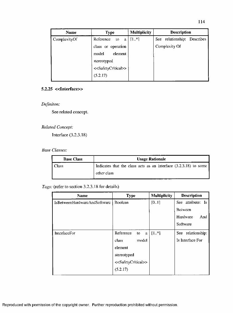
114
Name Type Multiplicity Description
ComplexityOf Reference to a
class or operation
model element
stereotyped
«SafetyCritical»
(5.2.17)
See relationship: Describes
Complexity Of
5.2.25 « I n te r fa c e »
Definiton:
See related concept.
Related Concept:
Interface (3.2.3.18)
Base Classes:
Base Class Usage Rationale
Class Indicates that the class acts as an interface (3.2.3.18) to some
other class
Tags: (refer to section 3.2.3.18 for details)
Name Type Multiplicity DescriptionIsBetweenHardwareAndSoftware Boolean [0..1] See attribute: Is
Between
Hardware And
Software
InterfaceFor Reference to a
class model
element
stereotyped
«SafetyCritical»
(5.2.17)
[1..*] See relationship:
Is Interface For
Reproduced with permission of the copyright owner. Further reproduction prohibited without permission.

115
Name Type Multiplicity DescriptionProtocolID String [0..1] See attribute:
Protocol ID
InputFunctionParameter Expression [0..*] See attribute:
Input Function
Parameters
OutputFunctionParameter Expression [0.*] See attribute:
Output Function
Parameters
5.2.26 « C o n c u r r e n t»
Definiton:
See related concept.
Related Concept:
Concurrent (3.2.3.19)
Base Classes:
Base Class Usage RationaleClass To identify the concurrency (3.2.3.19) role (e.g. active, passive,
resource, ... etc) that a specific class assumes in the model
Tags: (refer to section 3.2.3.19 for details)
Name Type Multiplicity DescriptionRole Enumeration [0..1] See attribute: Role
IsShared Boolean [0..1] See attribute: Is Shared
Reproduced with permission of the copyright owner. Further reproduction prohibited without permission.
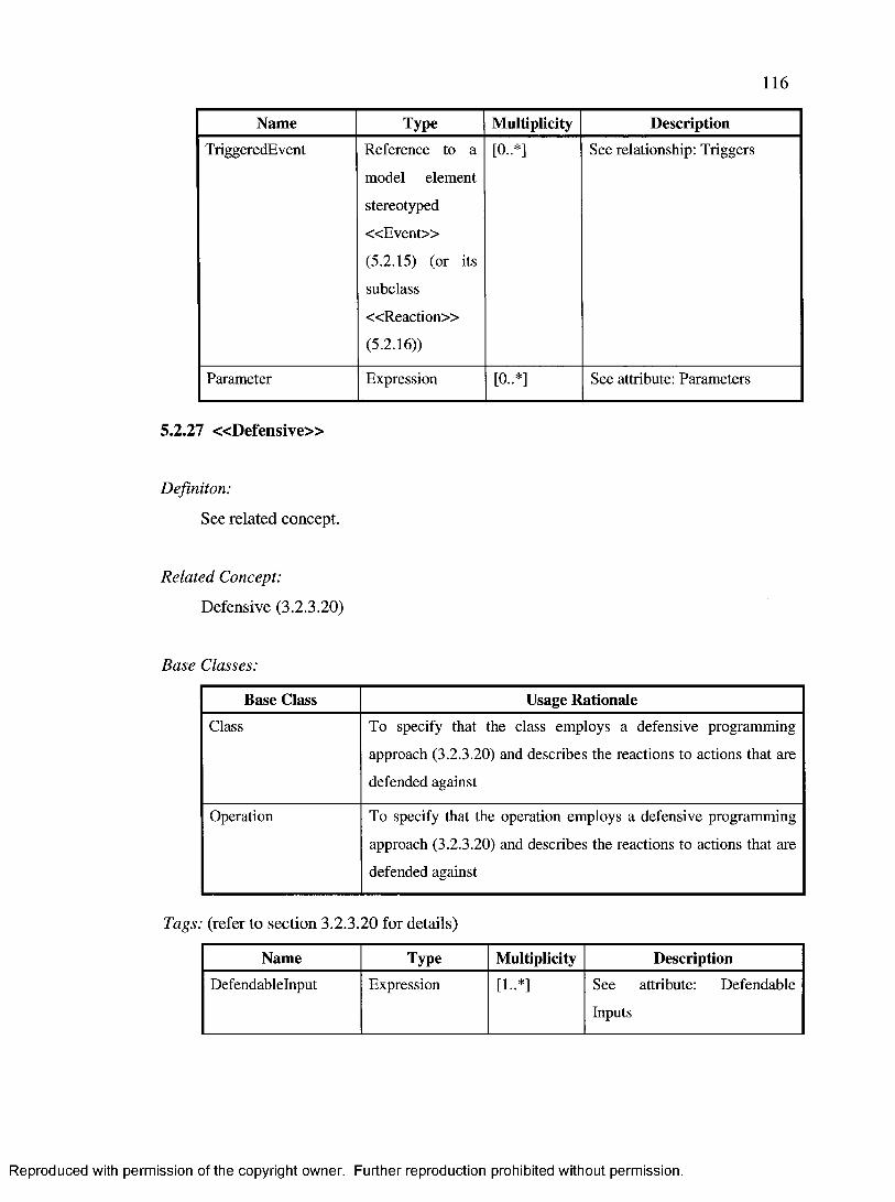
116
Name Type Multiplicity DescriptionTriggeredEvent Reference to a
model element
stereotyped
« E v e n t»
(5.2.15) (or its
subclass
« R eac tio n »
(5.2.16))
[0..*] See relationship: Triggers
Parameter Expression [0..*] See attribute: Parameters
5.2.27 « D e fe n s iv e »
Definiton:
See related concept.
Related Concept:
Defensive (3.2.3.20)
Base Classes:
Base Class Usage RationaleClass To specify that the class employs a defensive programming
approach (3.2.3.20) and describes the reactions to actions that are
defended against
Operation To specify that the operation employs a defensive programming
approach (3.2.3.20) and describes the reactions to actions that are
defended against
Tags: (refer to section 3.2.3.20 for details)
Name Type Multiplicity DescriptionDefendablelnput Expression [1..*] See attribute: Defendable
Inputs
Reproduced with permission of the copyright owner. Further reproduction prohibited without permission.

117
Name Type Multiplicity Description
Reaction Reference to a
model element
stereotyped
« R eac tio n »
(5.2.16)
[1..*] See relationship: Performs
5.2.28 « C o n fig u r a b le »
Definiton:
See related concept.
Related Concept:
Configurable (3.2.3.22)
Base Classes:
Base Class Usage RationaleClass To specify that the class can be configured (3.2.3.22) to produce a
different configuration (3.2.3.21) with a different behaviour
Tags: (refer to section 3.2.3.22 for details)
Name Type Multiplicity Description
Kind Enumeration [0..1] See attribute: Kind
When Enumeration [0..1] See attribute:
When
DefaultConfiguration Reference to a model
element stereotyped
«ConfigurationContext»
(5.2.8)
[1-1] See relationship:
Is Defaulted To
Reproduced with permission of the copyright owner. Further reproduction prohibited without permission.

118
Name Type Multiplicity Description
ProducibleConfiguration Reference to a model
element stereotyped
«ConfigurationContext»
(5.2.8)
[1..*] See relationship:
Is Configurable To
5.2.29 « L o a d a b le »
Definiton:
See related concept.
Related Concept:
Loadable (3.2.3.23)
Base Classes:
Base Class Usage Rationale
Class To specify that the class can be loaded (3.2.3.23) on some other
configurable (3.2.3.22) class to produce a different configuration
(3.2.3.21)
Tags: (refer to section 3.2.3.23 for details)
Name Type Multiplicity Description
LoadableOn Reference to a model
element stereotyped
«C onfigurable» (5.2.28)
[1..*] See relationship: Is
Loadable On
B aseConfiguration Reference to a model
element stereotyped
«ConfigurationContext»
(5.2.8)
[0..*] See relationship:
Requires
Reproduced with permission of the copyright owner. Further reproduction prohibited without permission.

119
Name Type Multiplicity DescriptionResultantConfiguration Reference to a model
element stereotyped
«ConfigurationContext»
(5.2.8)
[1..*] See relationship:
Produces
5.2.30 « C o n fig u r a to r »
Definiton:
See related concept.
Related Concept:
Configurator (3.2.3.24)
Base Classes:
Base Class Usage RationaleClass To specify that the class can configure configurable (3.2.3.22)
classes to change the configuration (3.2.3.21) (and thus produce a
different behaviour)
Operation To specify that the invoking the operation can configure
configurable (3.2.3.22) classes to change the configuration
(3.2.3.21) (and thus produce a different behaviour)
Tags: (refer to section 3.2.3.24 for details)
Name Type Multiplicity DescriptionConfigurableEntity Reference to a
model element
stereotyped
«Configurable»
(5.2.28)
[1..*] See relationship: Configures
Reproduced with permission of the copyright owner. Further reproduction prohibited without permission.

120
Name Type Multiplicity DescriptionConfigurationEntity Reference to a
model element
stereotyped
« L o ad ab le»
(5.2.29)
[1..*] See relationship: Loads
5.2.31 « R e p lic a te d »
Definiton:
See related concept.
Related Concept:
Replicated (3.2.3.25)
Base Classes:
Base Class Usage RationaleClass To indicate that class is replicated (3.2.3.25)
Tags: (refer to section 3.2.3.25 for details)
Name Type Multiplicity DescriptionID String [0..1] See attribute: ID (Replicated)
ReplicationGroupID String [0..1] Identifies the ReplicationGroup
(3.2.3.27), specified using the
«ReliabilityContext» (5.2.2)
stereotype, which owns this
replicated instance.
See relationship: Owns
(ReplicationGroup)
Reproduced with permission of the copyright owner. Further reproduction prohibited without permission.
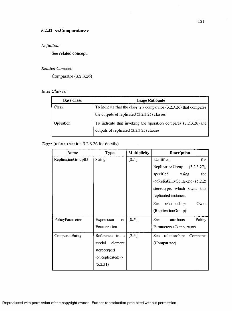
121
5.2.32 « C o m p a r a to r »
Definiton:
See related concept.
Related Concept:
Comparator (3.2.3.26)
Base Classes:
Base Class Usage RationaleClass To indicate that the class is a comparator (3.2.3.26) that compares
the outputs of replicated (3.2.3.25) classes
Operation To indicate that invoking the operation compares (3.2.3.26) the
outputs of replicated (3.2.3.25) classes
Tags: (refer to section 3.2.3.26 for details)
Name Type Multiplicity DescriptionReplicationGroupID String [0..1] Identifies the
ReplicationGroup (3.2.3.27),
specified using the
«ReliabilityContext» (5.2.2)
stereotype, which owns this
replicated instance.
See relationship: Owns
(ReplicationGroup)
PolicyParameter Expression or
Enumeration[0..*] See attribute: Policy
Parameters (Comparator)
ComparedEntity Reference to a
model element
stereotyped
«R eplicated»
(5.2.31)
[2..*] See relationship: Compares
(Comparator)
Reproduced with permission of the copyright owner. Further reproduction prohibited without permission.

122
5.3 Examples
This section presents examples of software models using the proposed UML profile. The
examples are explained in detail, and they serve to help the reader better understand the
UML profile and how it can be used.This thesis discusses a total of nine examples (plus a
case study in section 7). Three of those examples are discussed below as they primarily
use concepts (and stereotypes) that are key to the airworthiness standard (e.g., the notion
of software level) or that are not supported by other UML profiles. The reminaing six
examples are discussed in . Appendix G. The examples are also stereotyped according to
Gomaa’s class classification as presented in [7] and summarized in Appendix E.
5.3.1 Hardware/Software Interfaces
The example in Figure 8 shows a Kalman filter and how it connects to the radar that
provides its input and a simulator of the outside world’s events.
Kalman filters are recursive functions. Therefore, KaimanFiiter is stereotyped with
«Im plem entationS ty le» (5.2.11) whose “Kind” tagged value is set to “Recursive”.
The project in which this system is developed has a coding standard requirement that says
that “recursive algorithms shall not be used”. Therefore the KaimanFiiter class is also a
deviation, or a violation, of the coding standard requirement, and is stereotyped with
« D e v ia t io n » (5.2.10) whose “Kind” tagged value is set to
“UsingRecursiveAlgorithm”. The “Reference” tagged value is set to “CodingStandard” to
indicate that using recursive algorithms is a deviation from, or a violation of, the project’s
coding standard.
Reproduced with permission of the copyright owner. Further reproduction prohibited without permission.

123
Furthermore, filters are time-related functions. Therefore, KaimanFiiter is also
stereotyped with «B eh av io u ra lS ty le» (5.2.12) whose “Kind” tagged value is set to
“Time-Related”.
Now, Kalman filters process radar outputs. Since this example has a software
implementation for the Kalman filter, it has to interface with the actual radar hardware on
the aircraft. For this reason, Radarinterf ace is available to provide an interface between
the software Kalman filter and the hardware radar device. Thus, Radarinterface is
stereotyped with « I n te r f a c e » (5.2.25) whose “IsBetweenHardwareAndSoftware”
tagged value is set to “true”. The “InterfaceFor” tagged value indicates that
Radarinterface is an interface for the actual radar hardware.
The testing of such systems is often performed in system integration labs. In other words,
the software is not loaded on the aircraft and the aircraft flown just to perform software
unit or integration testing. That would just be too expensive! Therefore, a software
simulator is developed to simulate world events that happen outside of the aircraft. This
simulator is ReaiworidEventsimuiator and is stereotyped with « S im u la to r »
(5.2.21). The “SimulatedEntity” tagged value indicates that it simulates the input to
Radarinterface. Furthermore, the “SimulationParameter” tagged value indicates that
the inputs exhibit a stochastic Poisson process with an average inter-arrival time of 20
milliseconds.
All the information described above is relevant for two purposes. First, it describes how
software was designed to improve the development process - this was achieved, as
described above, by using a simulator to improve the testing process and a
Reproduced with permission of the copyright owner. Further reproduction prohibited without permission.

124
hardware/software interface to provide communication between radar hardware and
Kalman filter software. Simulators are often used to test systems [1]. Therefore, the
whole diagram is stereotyped with « D esig n C o n tex t» (5.2.7) to indicate that this design
setup is of special interest. Secondly, the modeled classes contain information that is
relevant for the software certification aspects. For example, the airworthiness standard
specifies that the certification authorities need to know about all hardware/software
interfaces and deviations from plans or standards. Therefore, the diagram is stereotyped
with «C ertificationC ontex t» (5.2.6) to indicate that it contains information relevant for
the certification of the software in this diagram.
«D esignC ontext»«CertificationContext»
Reads Simulator Outputs
Reads Radar Outputs
« in p u t device interface»
« ln te r fa c e »{lsBetweenHardwareAndSoftware=true
lnterfaceFor=RadarHardware}
Radarinterface
« a lg o rith m »
« S im u la to r» {SimulatedEntity=“Radarlnput” ,
SimulatorParameter=(Poisson, Lamba=20ms)}
RealWorldEventSimulator
« a lg o rith m »
«lm plem entationStyle» {Kind=Recursive}
«D e v ia tio n »{Kind=UsingRecursiveAlgorithm
Reference=CodingStandard}
«BehaviouraIStye» {Kind=Time-Related}
KaimanFiiter
Figure 8: Kalman filter processing input, through an interface, from a simulator
(structure).
5.3.2 Contributions to Failure Conditions
The example Figure 9 shows software that controls the landing wheels of the aircraft.
pilotKeyboar dint erf ace is an interface to the keyboard used by the aircraft’s pilots to
deploy or hide the landing wheels when desired. An aircraft normally has two pilots, so it
Reproduced with permission of the copyright owner. Further reproduction prohibited without permission.

125
is likely that there will be several keyboards that can command
LandingWhee is Controller to deploy or hide the landing wheels.
LandingWheeisControiier communicates with the landing wheel hardware, through
LandingWheel sinter face, and can command it to hide or deploy the wheels. The
wheels are deployed when the aircraft is on the ground or about to land. Since
LandingWheel sinter face is an interface for the landing wheel hardware, it is
stereotyped with « In te r f a c e » (5.2.25), its “IsBetweenHardwareAndSoftware” tagged
value is set to “true”, and its “InterfaceFor” tagged value is set to “LandingWheels”.
LandingWheeisControiier is a safety-critical element as well because it must ensure
that the landing wheels are deployed when the aircraft is on the ground or it is at a low
altitude because it is landing. If the landing wheels are not deployed when the aircraft is
on the ground or is landing, then this could result in fatal injuries to the aircraft
occupants. In the context of airworthiness, such software is assigned is assigned level B.
Therefore, LandingWheeisControiier is stereotyped with « S a fe ty C ritic a l» (5.2.17)
and its “CriticalityLevel” tagged value is set to “B”. This is also why this diagram was
stereotyped with « S a fe ty C o n te x t» (5.2.1). Because it depends on
LandingWheel sinter face, the airworthiness rules specify that
LandingWheel sinter face must also be safety-critical and have a software level equal to
at least the highest level of all classes that depend on it. In this example,
LandingWheel sinter face is stereotyped with « S a fe ty C ritic a l» (5.2.17) and is
assigned “CriticalityLevel” equal to that of LandingWheeisControiier, namely level
“B”.
Reproduced with permission of the copyright owner. Further reproduction prohibited without permission.

126
To ensure a higher level of safety, LandingWheeisControiier implements defensive
programming mechanisms by ensuring that the pilot does not attempt to hide the landing
wheels when they shouldn’t. Defensive programming is common when developing user
interfaces. In this example, LandingWheeisControiier defends against the pilot’s
attempt to hide the landing wheels when the aircraft’s altitude is less than 100 meters by
keeping the landing wheels deployed. This is explicitly specified by stereotyping
LandingWheeisControiier with the « D e fe n s iv e » (5.2.27) stereotype and specifying
its “Defendablelnput” and “Reaction” tagged values. (The KeepWheelsDeployed model
element stereotyped « R e a c t io n » is not shown in the diagram: It would be an operation
of the LandingWheelsInterface class.)
LandingWheeisControiier determines the aircraft’s altitude by reading the radar output
from Radarinterface. Radarinterface was explained in detail in section 5.3.1.
However, it has also been stereotyped here with « S a fe ty C ritic a l» (5.2.17) to explicitly
specify the fact that some safety-critical functionality, such as
LandingWheeisControiier, depends on it. Moreover, it has also been stereotyped with
« C o m p le x ity » (5.2.24) and its “Measure” and “Value” tagged values indicate that the
implementation must not have a “Big-O” larger than “n2 (where the meaning of “n” is
dependent on the algorithm in context). This is because radars usually have high
frequency inputs, so the code of the corresponding interfaces must be optimized.
Furthermore, Radarinterface is monitored by RadarDataValidator.
RadarDataValidator is a monitor whose purpose is to ensure that Radarinterface
produces high-integrity information (i.e. high precision and accuracy). This is specified
Reproduced with permission of the copyright owner. Further reproduction prohibited without permission.
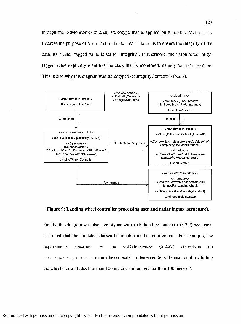
127
through the « M o n i to r » (5.2.20) stereotype that is applied on RadarDataValidator.
Because the purpose of RadarvaiidatorDatavaiidator is to ensure the integrity o f the
data, its “Kind” tagged value is set to “Integrity” . Furthermore, the “MonitoredEntity”
tagged value explicitly identifies the class that is monitored, namely Radarinterface.
This is also why this diagram was stereotyped « In teg rity C o n tex t» (5.2.3).
«S afetyC ontext»«ReliabilityContext»« ln tegrityC ontext»
Commands Monitors
1 Reads Radar Outputs 1
Commands
« in p u t device interface»
PilotKeyboardlnterface
« a lg o rith m »
« M o n ito r» {Kind=lntegrity MonitoredEntity=Radarlnterface}
RadarDataValidator
« ou tpu t device in terface»
« ln te r fa c e »{lsBetweenHardwareAndSoftware=true
lnterfaceFor=LandingWheels}
«S a fe tyC ritica l» {CriticalityLevel=B}
LandingWheelsInterface
« s ta te dependent con tro l»
«S afe tyC ritica l» {CriticalityLevel=B}
« D e fe ns ive»{Defendablelnput^
‘Altitude < 100 m && Command=“HideWheels”’ Reaction=KeepWheelsDeployed}
LandingWheeisControiier
« C o m p le x ity» {Measure=Big-0, Value=“n2"}, ComplexityOf=Radarlnterface}
« ln te rfa c e »{lsBetweenHardwareAndSoftware=true
lnterfaceFor=RadarHardware}
Radarinterface
« in p u t device in terface»
«S a fe tyC ritica l» {CriticalityLevel=B}
Figure 9: Landing wheel controller processing user and radar inputs (structure).
Finally, this diagram was also stereotyped with « R eliab ilityC on tex t» (5.2.2) because it
is crucial that the modeled classes be reliable to the requirements. For example, the
requirements specified by the « D e fe n s iv e » (5.2.27) stereotype on
LandingWheeisControiier must be correctly implemented (e.g. it must not allow hiding
the wheels for altitudes less than 100 meters, and not greater than 100 meters!).
Reproduced with permission of the copyright owner. Further reproduction prohibited without permission.

128
5.3.3 Software Configurations
The diagram in Figure 10 shows a configurable user interface. The user interface interacts
with the users by displaying text in their language of preference, userinterface itself is
language-independent. It reads and displays textual strings in any of three languages:
English, French, and German. This is achieved through userinterfaceDictionary,
which is stereotyped with « C o n fig u ra b le » (5.2.28) to indicate that the user can change
its configuration. The “Kind” tagged value is set to “Lookup-Table” and the “When”
tagged value is set to “Run-Time” to indicate that look-up tables can be loaded into it at
run-time to change its configuration. The “DefaultConfiguration” tagged value specifies
that the “Englishlnterface” is the default configuration for UserinterfaceDictionary.
The possible configurations that can result from such a load are listed in the
“ProducibleConfiguration” tagged values. In this example, we have three possible
configurations that can result from such a load: “Englishlnterface”, “Frenchlnterface”,
and “Germanlnterface”.
DictionaryLoader is the actual software than can perform the software load and
therefore change the software configuration. Thus, it is stereotyped with
« C o n fig u ra to r» (5.2.29). The “ConfigurableEntity” tagged value identifies the class
that can be configured, namely userinterfaceDictionary. The “ConfigurationEntity”
tagged values identify the classes that can be loaded on the “ConfigurableEntity”, namely
EnglishDictionaryTable, FrenchDictionaryTable, and GermanDictionaryTable,
which are stereotyped with « L o a d a b le » (5.2.29) to indicate that they can be loaded in
appropriate situations. The “LoadableOn” tagged values are set to
“UserinterfaceDictionary” to indicate that they are loadable on
Reproduced with permission of the copyright owner. Further reproduction prohibited without permission.

129
UserinterfaceDictionary, and the “ResultantConfiguration” specifies which
configuration is produced by loading EnglishDictionaryTable,
FrenchDictionaryTable, and GermanDictionaryTable, which are
Englishlnterface, Frenchlnterface, and Germanlnterface, respectively.
The diagram is stereotyped with «C onfigurationC ontex t» (5.2.8) to indicate that it
contains information that is relevant to changing software configurations.
«ConfigurationContext»
Reads
1 Configures 1
LoadsReads
« u s e r interface»
Userlnterface
DictionaryTable« e n ti ty »
« e n ti ty »
« L o a d a b le »{LoadableOn=UserlnterfaceDictionary,
ResultantConfiguration=Englishlnterface}
EnglishDictionaryTable
« e n t i ty »
« L o a d a b le »{LoadableOn=UserlnterfaceDictionary,
ResultantConfiguration=Frenchlnterface}
French DictionaryT able
« e n ti ty »
« L o a d a b le »{LoadableOn=UserlnterfaceDictionary,
ResultantConfiguration=Germanlnterface)
German DictionaryT able
« e n t i ty »
« C on figurab le» {Kind=Lookup-Table, When=Run-Time, DefaultConfiguration=‘Englishlnterface’,
ProducibleConfiguration='Englishlnterface’, ProducibleConfiguration=‘Frenchlnterface’, ProducibleConfiguration=‘Germanlnterface’,
________ UserinterfaceDictionary________
« coo rd ina to r»
«C on figura to r»{ConfigurableEntity=‘UserlnterfaceDictionary’,ConfigurationEntity=‘EnglishDictionaryTable',ConfigurationEntity='FrenchDictionaryTable’,ConfigurationEntity=‘GermanDictionaryTable’}
DictionaryLoader
Figure 10: User interface language configurations (structure).
5.4 Development Methodology
The proposed UML profile provides a mechanism to model safety information in UML
models. However, such mechanism is only a part of an overall process for developing
Reproduced with permission of the copyright owner. Further reproduction prohibited without permission.

130
airworthiness-compliant software. A methodology for developing airworthiness-
compliant software products is shown in Figure 11. In practice, it is likely that a step
starts before its previous step is fully completed and closed. The different steps are
further described below.
StartS -1 : Define the system ’s
high-level functional requirem ents
S-2: Define the system architecture
identified?S-5: Perform a critical review
S-7: Develop the subsystem s’ detailed design while
monitoring safetyS-8: Certify system
S-3: Develop th e detailed functional and non-functional,
excluding safety, requirem ents
(S-4: Perform a safety a sse ssm en t and develop safety requirem ents
Figure 11: Development methodology of airworthiness-compliant software products.
Each step in Figure 11 is explained in Table 4.
Step Description
S-1 Define the system’s high-level functional requirementsActivity: The system boundaries, behaviour, and high-level requirements are defined. The system’s boundaries define what consistutes part of the system, and what does not. This is an important aspect for analysing the safety aspects of the system, as whether a system is safe or not depends on what is considered part of the system and what is not. In addition, the system’s general behaviour, along with the high-level functional requirements, are defined. At the end of this step, the system’s behaviour is understood and documented.Output: The documented behaviour of the system, usually presented as the system’s high-level functional requirements based on the definition of the system boundaries.
Reproduced with permission of the copyright owner. Further reproduction prohibited without permission.

131
Step Description
S-2 Define the system architectureActivity: The system architecture is defined based on its high-level functional requirements. The various subsystems are defined, and the role of each subsystem in implementing the system’s high-level functional requirements are defined and documented. As a result, the high-level functional requirements for each subsystem are defined. The proposed UML profile may be used to model the system architecture.Output: The system architecture, including the identification and definition of its subsystems.
S-3 Develop the detailed functional and non-functional excluding, safety, reauirementsActivity: Detailed functional requirements are developed for the system and its subsystems. In addition, non-functional requirements, excluding safety requirements, are developed.Output: Detailed functional and non-functional, excluding safety, requirements of the system and its subsystems.
S-4 Perform a safety assessment and develop safety reauirementsActivity: By this stage, the behaviour of the system and its subsystems is already understood. In this step, therefore, a safety assessment of the system is performed based on its architecture and intended behaviour, and using one or more safety assessment methods such as the ones identified in section 2.1. The results of the safety assessment are translated into safety requirements, and then the safety requirements are assigned to the various subsystems. This step includes USAGE 1 as defined in section 2.4.Output: Safety hazards identified in the safety assessment, and safety requirements for the system and its subsystems.
S-5 Perform a critical reviewActivity: The output of steps S-1 - S-4 are checked for consistency among each other. Areas of interest in this step are whether the safety requirements are complete with respect to the functional and non-functional requirements, and whether there are any ambiguous, missing, or conflicting requirements. In addition, the system architecture is analysed to determine whether there exists a more suitable architecture for the identified safety requirements. Thus, the results of the previous SI - S4 steps iteration are analysed, which will be later used to determine whether another iteration is necessary or not. In practice, such critical reviews are common to hold with the project’s customer at selected milestones.Output: A list of identified issues to be fixed. This list may be empty, but this will be surprising unless steps S-1 - S-5 have already gone through at least two iterations.
Reproduced with permission of the copyright owner. Further reproduction prohibited without permission.

132
Step Description
S-6 Are any issues identified?Activity: The results from step S-5 are analysed. If any issues are encountered, step S-1 is revisited to correct all identified issues. Otherwise, development is progressed to step S-7.Output: The decision on whether to perform another iteration of steps S-1 - S-5 or not.
S-7 Develop the subsystems’ detailed design while monitoring safetyActivity: The subsystems’ detailed design is developed. The detailed design will also include the specification of the system’s events of interest, and the desired reactions to those events. The definition of the events and reactions will depend on the safety requirements of the system. The proposed UML profile is used to design the subsystems (USAGE 2 in section 2.4), and the design decisions are justified (USAGE 3 in section 2.4). The design elements are traced back to the requirements using the proposed UML profile’s stereotypes. While the subsystems are being designed, the design’s conformance to the safety requirements is continuously monitored (USAGE 4 in section 2.4). In practice, software implementation also occurs in this step.Output: The detailed design of the subsystems, the system events and reactions, the justifications of the design decisions, and the safety monitoring information.
S-8 Certify systemActivity: The project’s safety and airworthiness engineers are engaged with the certification authority to demonstrate the project’s compliance with the certification requirements. In this step, safety information is obtained from the software (USAGE 5 in section 2.4), and evidence of performing relevant activities (such as USAGE 1, USAGE 2, USAGE 3, and USAGE 4 in section 2.4) are presented. Any issues identified by the certification authority are corrected and the certification is ensured to completion.Output: Successful certification of the system.
Table 4: Details of the development methodology steps.
Reproduced with permission of the copyright owner. Further reproduction prohibited without permission.
133
6 GENERATION OF CERTIFICATION INFORMATION
Now that a UML profile is defined, it can be used to model software that requires
certification according to the airworthiness standard. This section shows how a UML
model using the proposed UML profile can be used to automatically generate information
that can either be submitted to the certification authorities, or can be used to track issues
of relevance to the certification authorities. In either case, this information improves
communication between airworthiness engineers and software engineers. The
information required for submission to the certification authorities for each software level
is listed in section 11 and annex A in the airworthiness standard, RTCA DO-178B [4].
6.1 Technological Requirements
In order to be able to generate certification information from UML models, there are
technological requirements that software development tools must support. Those
requirements can be summarized in one requirement, namely the ability to search UML
models based on the stereotypes that are applied to model elements and the values of the
stereotypes’ tagged values.
For example, consider a scenario when one needs to identify all safety-critical model
elements. In this case, the modeling tool must be able to search the UML model and
identify all model elements, such as classes in class diagrams, that have been stereotyped
with « S a fe ty C ritic a l» (5.2.17). If the user of the tool needs to identify all safety-
critical model elements that are assigned software level A, for example, then the tool
must be able to read the “CriticalityLevel” tagged value of the « S a fe ty C ritic a l»
Reproduced with permission of the copyright owner. Further reproduction prohibited without permission.

134
(5.2.17) stereotype and identify when it is set to “A”. This is why the proposed UML
profile emphasizes specifying information in machine-readable language.
In practice, there are several possible methods to achieve this technological requirement
of being able to search UML models. Below is a list of some methods to guide the users
of the proposed UML profile.
6.1.1 Integrated Support in UML Modeling Tools
One convenient method to extract safety information from UML models is to provide a
mechanism to do so in the UML modeling tool itself. UML modeling tools already offer
some sort of search capabilities for the designers. For example, ARTiSAN Studio [31],
which is a UML modeling tool from ARTiSAN Software Inc., allows designers to
identify where specific model elements are used. That is one example of ARTiSAN’s
search capabilities. Another example of a modeling tool is International Business
Machines Corporation’s (IBM) Rational Software Architect [32]. A third example is
Telelogic’s Rhapsody [33], This UML model-driven development tool allows designers
to search UML models for uses of specific stereotypes. In addition, it supports the Visual
Basic for Applications (VBA) scripting language, which allows modelers to write their
own scripts and execute them on models. This could be used to perform search queries.
The Eclipse Modeling Framework (EMF) for Java [34] is a popular, and easily
extensible, software development framework. Some of EMF’s extensions include the
capability to use the Object Constraint Language (OCL) [35] to specify search queries on
UML models, and then write Java code to execute them. Examples of the search
capabilities of this technology include the capability to search for all objects that are
Reproduced with permission of the copyright owner. Further reproduction prohibited without permission.

135
instances of a specific class. However, the current state of this technology does not
support searching UML models based on the stereotypes applied to model elements and
the values assigned to the tagged values. Nevertheless, the integration of EMF and OCL
is a promising approach that should be easibly extensible to support search queries based
on stereotypes and tagged values.
6.1.2 Exporting UML Models using XMI
XMI [36] is an OMG standard for representing, and therefore exchanging, models and
metadata in an XML-based language.
In practice, UML modeling tools can export UML models in the XMI language. This
would create an XML file containing all the model data. Since XMI is a standard format,
it can be imported by any other tool, thus establishing a common format across different
tools. For example, imagine project A that is using Rational Software Architect to model
its software. Further, assume that project A is similar in nature to a previously completed
project B that used ARTiSAN Studio to model its software. Project A now wants to reuse
the software model from project B. To achieve this, one would use a feature from
ARTiSAN Studio that would export an XMI file containing all the software model for
project B. Then, project A can import this XMI file using an import XMI file feature in
Rational Software Architect. Thus, the model would be transfered from project B to
project A.
In our case of generating certification information, the model would be exported from the
modeling tool by generating an XMI file. Once an XMI file containing the software
model is available, it can be easily parsed and searched. This is possible in many ways,
Reproduced with permission of the copyright owner. Further reproduction prohibited without permission.
136
but the most appropriate method would probably involve the use of the Extensible
Stylesheet Language (XSL) [37]. XSL is used to parse and transform XML-based files,
such as XMI files, to any desired format. Such transformation is achieved by using XSL
files called stylesheets. The purpose of XSL stylesheets is then to display the same model
data in different formats or views, just like the Model-View-Controller (MVC) software
pattern displays the same model information in different views. Using this approach, XSL
stylesheets can be developed to execute search queries on the model data in the XMI
files.
6.2 Examples
The examples presented below are specified in a high-level Structured Query Language
(SQL)-like language. It is intended to be pseudocode-like, result in shorter text (see
below), and be implementation-independent. Developers can also use them to implement
using existing development tools and frameworks (refer to documentation of the existing
tools and frameworks for more detail). It does not require the reader to have any
knowledge of other tools or frameworks. The grammar for the language used is specified
in an extension of the Extended Backus-Naur Form (EBNF), which is a popular syntax
for specifiying languages [38]. The EBNF language itself is specified in the EBNF
standard [39]. One popular example of a language specified in EBNF is the Ada language
as specified in the Ada 95 Language Reference Manual [40].
The EBNF meta-symbols used in this section are:
1. means “is defined as”.
Reproduced with permission of the copyright owner. Further reproduction prohibited without permission.

137
2. “I” means “or” .
3. Literal strings are enclosed in double-quotes
4. Angle brackets “<>” are used around category names.
5. Optional items (zero or one) are enclosed in square brackets “[]”.
6. Repetitive items (zero or more) are enclosed in braces “{}”.
The grammar for the search language used in this section, represented in EBNF form, is:
<search-query> ::= "SEARCH FOR " <subject> [" " <stereotype-criteria>]
< su b ject> : :== "all model elements"
< s te r e o ty p e - c r i t e r ia > ::= "STEREOTYPED WITH (" <stereotype-criterion> ") {" AND STEREOTYPED WITH (" <stereotype-criterion> } ")"
< s te r e o ty p e -c r it e r io n > ::= "<<" <stereotype-name> ">>" [ctagged-value-criteria]
<stereotyp e-nam e> ::= <string>
< t a g g e d -v a lu e -c r it e r ia > "WITH TAGGED VALUE (" <tagged-value-criterion> ") " {"AND WITH TAGGED VALUE (" <tagged-value-criterion>" ) " }
< ta g g e d -v a lu e -c r ite r io n > ::= <tagged-value-name> "=" <tagged-value> | <tagged-value-element-dereference> "IS " <stereotype-criteria>
< ta g g e d -v a lu e -e le m e n t-d e r e fe r e n c e > ::= <tagged-value-name> ".Element"
<tagged=value-nam e> ::= <string>
The < ta g g e d -v a iu e -e ie m e n t-d e r e fe r e n c e > is used to obtain the model element to
which a tagged value refers.
6.2.1 Hardware/Software Interfaces
Section 11.1 bullet a. in the airworthiness standard RTCA DO-178B [4] requires that the
project’s Plan for Software Aspects of Certification (PSAC), which is submitted to the
Reproduced with permission of the copyright owner. Further reproduction prohibited without permission.

138
certification authority, include a description of hardware/software interfaces in the
system. Furthermore, section 11.9 bullet f. in the airworthiness standard RTCA DO-178B
[4] requires that hardware/software interfaces be documented and the requirements of
their protocols, frequency of input, and frequency of outputs be presented.
A list of hardware/software interfaces can be extracted from the model using the
following search query:
SEARCH FOR all model elements STEREOTYPED WITH («Interface»
WITH TAGGED VALUE (IsBetweenHardwareAndSoftware = true))
From the results of this query, the “ProtocolID”, “InputFunctionParameter”, and
“OutputFunctionParameter” tagged values of the « In te r f a c e » (5.2.25) stereotype can
be read to present the information described above. For example, executing this search
query on the model in Figure 8 gives the following results: Radarinterface.
6.2.2 Contributions to Failure Conditions
Section 11.1 bullet c. in the airworthiness standard RTCA DO-178B [4] requires that the
project’s PS AC include a description of software’s contributions to failure conditions.
A list of software that can contribute to failure conditions, along with the severity of the
failure conditions, can be extracted from the model using the following search query:
SEARCH FOR all model elements STEREOTYPED WITH
(<<SafetyCritical>>)
From the results of this query, the “CriticalityLevel” tagged value of the
« S a fe ty C ritic a l» (5.2.17) stereotype can be read to identify the failure condition levels
Reproduced with permission of the copyright owner. Further reproduction prohibited without permission.

139
that each safety-critical software component contributes to. For example, executing this
search query on the model in Figure 9 gives the following results:
LandingWheelsControiler,LandingWheelsinterface, Radarinterface.
6.2.3 COTS Software
Section 11.1 bullet g. in the airworthiness standard RTCA DO-178B [4] requires that the
project’s PS AC include a description of COTS software used.
A list of COTS software can be extracted from the model using the following search
query:
SEARCH FOR all model elements STEREOTYPED WITH («Nature»
WITH TAGGED VALUE (Kind = COTS))
For example, executing this search query on the model in Figure 17 (discussed in
Appendix G .l) gives the following results: safeFiightPaths.
6.2.4 Software Partitioning
Section 11.3 bullet f. in the airworthiness standard RTCA DO-178B [4] requires that the
project specify which methods are used to verify the integrity of partitions performed.
Furthermore, section 11.9 bullet h. requires that partitioning requirements allocated to
software, as well as the software level(s) for each partition, be specified.
A list of partitions can be extracted from the model using the following search query:
SEARCH FOR all model elements STEREOTYPED WITH
(<<Partition>>)
Reproduced with permission of the copyright owner. Further reproduction prohibited without permission.
140
From the results of this query, the “PartitionedFrom” tagged value of the « P a r t i t io n »
(5.2.18) stereotype can be read to determine which software component this partition was
partitioned from. Furthermore, the “Reference” tagged value of the « P a r t i t io n »
(5.2.18) stereotype can be read to determine the requirement that resulted in this partition.
For example, executing this search query on the model in Figure 18 (discussed in
Appendix G.2) gives the following results: AutoPiiotControiier,
ConvertibleSteeringlnformation.
A list of partitions that have been assigned software levels, along with the software level
for each partition, can be extracted from the model using the following search query:
SEARCH FOR all model elements STEREOTYPED WITH
(<<Partition») AND STEREOTYPED WITH (<<SafetyCritical»)
From the results of this query, the “CriticalityLevel” tagged value of the
« S a fe ty C ritic a l» (5.2.17) stereotype can be read to determine the software level for
each partition. For example, executing this search query on the model in Figure 18 gives
the following results: AutoPiiotControiier.
6.2.5 Requirements and Traceability
Section 11.9 in the airworthiness standard RTCA DO-178B [4] requires that the software
requirements data be available. Furthermore, the airworthiness standard RTCA DO-178B
[4] requires that the software design (e.g. UML model) be traced to the software
requirements for software assigned level D or above. It also requires that the source code
be traceable to the requirements for software assigned level C or above.
Reproduced with permission of the copyright owner. Further reproduction prohibited without permission.
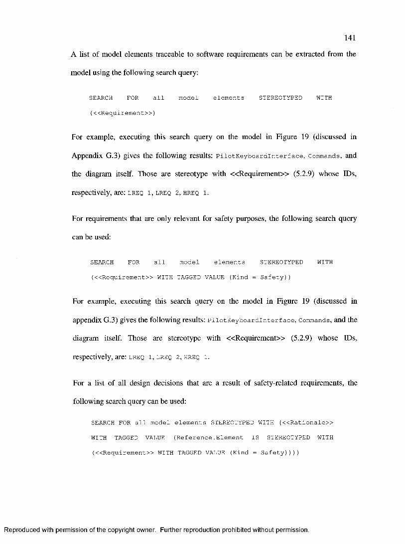
141
A list of model elements traceable to software requirements can be extracted from the
model using the following search query:
SEARCH FOR all model elements STEREOTYPED WITH
(<<Requirement>>)
For example, executing this search query on the model in Figure 19 (discussed in
Appendix G.3) gives the following results: PilotKeyboardlnterface, Commands, and
the diagram itself. Those are stereotype with « R e q u ire m e n t» (5.2.9) whose IDs,
respectively, are: lreq i, lreq 2, hreq i.
For requirements that are only relevant for safety purposes, the following search query
can be used:
SEARCH FOR all model elements STEREOTYPED WITH
(<<Requirement>> WITH TAGGED VALUE (Kind = Safety))
For example, executing this search query on the model in Figure 19 (discussed in
appendix G.3) gives the following results: PilotKeyboardlnterface, Commands, and the
diagram itself. Those are stereotype with « R e q u ire m e n t» (5.2.9) whose IDs,
respectively, are: lreq i, lreq 2, hreq i.
For a list of all design decisions that are a result of safety-related requirements, the
following search query can be used:
SEARCH FOR all model elements STEREOTYPED WITH («Rationale»
WITH TAGGED VALUE (Reference.Element IS STEREOTYPED WITH
(<<Requirement>> WITH TAGGED VALUE (Kind = Safety))))
Reproduced with permission of the copyright owner. Further reproduction prohibited without permission.

142
The search query can be read as follows: Find all model elements that are stereotyped
with « R a t io n a le » (5.2.14). Then, pick only those elements where the “Reference”
tagged value points to safety requirements (as indicated in the model with the
« R eq u ire m e n t» (5.2.9) stereotype and its “Kind” tagged value). Thus, the above
search query specifies that the results are all model elements that are stereotyped with
« R a t io n a le » (5.2.14), and where the “Reference” tagged value of the « R a t io n a le »
(5.2.14) stereotype is a reference to another model element stereotyped with
« R eq u ire m e n t» (5.2.9) whose “Kind” tagged value is “Safety”. For example,
executing this search query on the model in Figure 19 gives the following result:
SafeFlightPaths.
6.2.6 Multiple-Version Dissimilar Software
Section 11.1 bullet g. in the airworthiness standard RTCA DO-178B [4] requires that the
project’s PS AC include a description of the multiple-version dissimilar software used.
Furthermore, section 11.3 bullet j. in the airworthiness standard RTCA DO-178B [4]
requires that a description of the software verification process activities used to verify
multiple-version dissimilar software be presented.
A list of multiple-version dissimilar software can be extracted from the model using the
following search query:
SEARCH FOR all model elements STEREOTYPED WITH
(<<Replicated>>)
Reproduced with permission of the copyright owner. Further reproduction prohibited without permission.

143
For example, executing this search query on the model in Figure 20 (discussed in
Appendix G.4) gives the following results: RadarFilterl, RadarFilter2,
RadarFilter3.
6.2.7 Recursive Software
Section 11.7 bullet e. in the airworthiness standard RTCA DO-178B [4] requires that the
software design standards specify which constraints on the software design exist. Such
design constraints could require the exclusion of software recursion.
If software recursion is used, then its use can be identified in the model. A list of
recursive software can then be extracted from the model using the following search
query:
SEARCH FOR all model elements STEREOTYPED WITH
(<<ImplementationStyle>> WITH TAGGED VALUE (Kind =
Recursive))
For example, executing this search query on the model in Figure 8 gives the following
results: KalmanFilter.
If recursive software is not permitted by the software design standard but this rule was
broken for some reason in some place, then a list of similar deviations from the standard
can be extracted using the following search query:
SEARCH FOR all model elements STEREOTYPED WITH («Deviation»
WITH TAGGED VALUE (Kind = UsingRecursiveAlgorithm))
Reproduced with permission of the copyright owner. Further reproduction prohibited without permission.
144
From the results of this query, the “Reference” and “Explanation” tagged values of the
« D e v ia t io n » (5.2.10) stereotype can be read to determine the standard from which this
deviation existed and the rationale for this deviation. For example, executing this search
query on the model in Figure 8 gives the following results: KalmanFilter
Reproduced with permission of the copyright owner. Further reproduction prohibited without permission.
145
7 CASE STUDY - NAVIGATION CONTROLLER
In this section, an aircraft’s navigation system is analysed, and its navigation controller
subsystem is designed using the proposed UML profile (section 5.1). The goal is to
demonstrate, through a realistic case study the usefulness of the profile in the context of
the usage scenarios we defined (section 2.4). In order to be complete and provide enough
insights about the system to the reader, we also go through the development methodology
described in section 5.4.
Here is a mapping between the steps of the development methodology (Figure 11 in
section 5.4) and the subsections where they are addressed:
S-l Define the system’s high-level functional requirements: In section 7.1, an
overview of the system is introduced, which describes in high-level language
the major functionalities of the system.
S-2 Define the system architecture: The system architecture is presented and
explained in section 7.2.
S-3 Develop the detailed functional and nonfunctional requirements (excluding
safety): The functional requirements of the subsystem under study are presented
and explained in section 7.3.
S-4 Perform a safety assessment and develop safety requirements: A safety
assessment is performed in section 7.4 using four standard, complementary
Reproduced with permission of the copyright owner. Further reproduction prohibited without permission.

146
methods. Its results are presented in sections 7.4.1 - 7.4.4, from which the
safety requirements are derived and presented in section 7.4.5.
S-5 Perform a critical review: Due to space constraints, only the final results are
presented in this case study rather than the actual iterations used to develop the
system. Therefore, the results of this step are not presented.
S-6 Are any issues identified?: For the same reasons as above, the results of this
step are not presented.
S-7 Develop the subsystems’ detailed design while monitoring safety: The design of
the subsystem under study, including aspects related the defined safety
requirements, is presented in section 7.5.
S-8 Certify system: In section 7.6, the usage scenarios of our proposed UML profile
are discussed in the context of our case study. Their results are generally
submitted to the certification authorities to certify the system, particularly the
results of usage USAGE 5 (Get Safety Information), which are discussed in
section 7.6.5.
7.1 Overview
The navigation controller subsystem is used to control the aircraft’s flight paths through
both automatic pilot and manual input from the pilots.
Reproduced with permission of the copyright owner. Further reproduction prohibited without permission.

147
It is worth reviewing the following terminology before proceeding with the case study:
1. Fly-To-Point (FTP): An FTP specifies a location on earth that the aircraft plans to
fly to. For example, an aircraft flying from London to Paris will have at least one
FTP, which is Paris.
2. Latitude/Longitude (LAT/LONG): A LAT/LONG specifies a particular
geographic position on earth in latitude and longitude. LAT/LONG values are the
standard measures for specifying geographic positions in navigation systems. The
unit of both LAT and LONG are degrees, with LAT ranging from 90 South to 90
North, and Longitude ranging from 180 Westward to 180 Eastward. LAT/LONG
values are generally used to specify FTP positions.
3. Bearing: The bearing on an aircraft is the direction in which it is flying. The
bearing is generally specified in degrees, with a range of [0, 360[. A bearing of
zero is in a direction starting from the aircraft’s position and towards the North
Pole.
4. Dead-Reckoning: Dead-reckoning an aircraft’s position means that the aircraft’s
position is being approximated using a previously known position at a given point
of time, the current speed and bearing (direction). Ideally, the navigation system
uses a Global Positioning System (GPS) to determine the aircraft’s LAT/LONG
position. If the GPS system fails, however, the navigation system can then
approximate the position by dead-reckoning it.
Reproduced with permission of the copyright owner. Further reproduction prohibited without permission.
148
The aircraft’s navigation controller subsystem has the following primary responsibilities:
1. Autopilot (Automatic): Based on the source and destination of the aircraft, this
subsystem can choose an appropriate flight path. During the entire flight period, it
can also guide the aircraft by generating appropriate commands to the aircraft’s
wings and engines to change the speed and bearing (i.e. direction) as required.
2. Supporting Custom Flight Paths (Semi-Automatic): This subsystem can accept
commands from the pilots such as a specific position’s latitude and longitude
(LAT/LONG). Then, it controls the aircraft’s speed and bearing to get to the
desired FTP that was indicated by the pilot.
In order to perform such functionality, this subsystem needs to have continuous input
from the aircraft’s navigation system, which reports the current position and altitude of
the aircraft at all time. In addition, it needs to be able to command the aircraft’s wings
and engines to change the speed and bearing.
7.2 System Architecture
Recall that software safety is only meaningful within the context of the system in which
the software is used. As a result, it is mandatory to consider the system architecture as a
whole to determine the safety aspects of NavigationControiierSubsystem. The system
architecture, in which NavigationControiierSubsystem appears, is shown in Figure
12, and is discussed below. In the discussion, the rationale for assigning each software
level is explained. The software levels were defined in section 2.2.
Reproduced with permission of the copyright owner. Further reproduction prohibited without permission.

149
« S a f e t y C o n t e x t »
« S u b s y s te m » « S u b s y s te m » « S u b s y s te m »
« S a fe ty C r itic a l» {CriticalityLevel=B} « S a fe ty C r itic a l» {Critical ityLevel=D) « S a fe ty C r itic a l» {Critical ity Level=D}
M echanicalSteeringW heelSubsystem LEDDisplaySubsystemNavigationUserlnterfaceSubsystem
« S u b s y s te m »
«SafetyCritical»{CriticalityLevel=C}
« P a r t i t io n »{Partitioned From=NavigationSubsystem}
NavigationControiierSubsystem
« S u b s y s te m » « S u b s y s te m » « S u b s y s te m »
« S a fe ty Critical» { C riticaiity Level=A) « S a fe ty C r itic a l» {CriticalityLevel=C} « S a fe ty C r itic a l» {Critical ity Level=B}
W ingsAndEnginesSubsystem NavigationD atabaseSubsystem NavigationSubsystem
Figure 12: System architecture (structure).
The system is composed of the following subsystems:
1. WingsAndEnginesSubsystem: This subsystem represents the wings and the
engines of the aircraft, and is used to control them. Therefore, it is the most
important element to control the aircraft’s speed and bearing. Thus, it is safety-
critical and is assigned level A, as the « S a fe ty C ritic a l» (5.2.17) stereotype
illustrates, because its failure prevents the continued safe flight and landing. This
subsystem will not be considered any further in this case study.
2. Mechanical steer ingwheeiSubsy stem: This subsystem represents the pilots’
mechanical steering wheel. They can use it to manually change the aircraft’s
speed and bearing. Thus, it is safety-critical and is assigned level B, as the
« S a fe ty C ritic a l» (5.2.17) stereotype illustrates, because its failure prevents the
Reproduced with permission of the copyright owner. Further reproduction prohibited without permission.

150
pilots from performing their tasks correctly and accurately, but the aircraft’s speed
and bearing can still be controlled by other subsystems. This subsystem will not
be considered any further in this case study.
3. NavigationSubsystem: This subsystem represents the navigation system that
determines the current position, altitude, speed, and bearing of the aircraft through
a GPS system and other technologies. Thus, it is safety-critical and is assigned
level B, as the « S a fe ty C ritic a l» (5.2.17) stereotype illustrates, because its
failure prevents the pilots from performing their tasks correctly and accurately,
but the pilots can approximate the aircraft’s navigation information by observing
ground landmarks. This subsystem will not be considered any further in this case
study.
4. LEDDi splay Subsystem: This subsystem represents a simple Light-Emitting
Diode (LED) display to the pilots showing continuous navigation information as
it is read from the “Navigation” subsystem. LEDs are a classical kind of
information display technology. Thus, it is safety-critical and is assigned level D,
as the « S a fe ty C ritic a l» (5.2.17) stereotype illustrates, because its failure
increases the pilots’ workload and discomfort, but they can still read the
navigation information from NavigationUserlnterfaceSubsystem. In case
LEDDi splay Subsystem fails, they can approximate navigation information
through ground landmarks or through radio communication with ground stations
or other aircrafts. This subsystem will not be considered any further in this case
study.
Reproduced with permission of the copyright owner. Further reproduction prohibited without permission.

151
5. NavigationDatabaseSubsystem: This subsystem stores and manages all the
possible flight paths relevant to this aircraft. It is safety-critical and is assigned
level C, as the « S a fe ty C ritic a l» (5.2.17) stereotype illustrates, because the
NavigationControiierSubsystem subsystem (at level “C”) depends on it. This
is a rule in the airworthiness standard - components are assigned to the highest
level of the components whose operations depend on it. This subsystem will not
be considered any further in this case study.
6. NavigationControiierSubsystem: This subsystem is in charge of automatically
guiding the aircraft through pre-determined flight paths and FTPs. The pilots can
use it for the autopilot feature, or to fly to specific points. It is safety-critical and
is assigned level C, as the « S a fe ty C ritic a l» (5.2.17) stereotype illustrates,
because its failure increases the pilots’ workload and discomfort and may cause
injuries because the pilots will not necessarily be able to safely fly the aircraft
without it as this would require them to use the mechanical steering wheels. It is
partitioned away from NavigationSubsystem, as indicated by the « P a r t i t io n »
(5.2.18) stereotype, because it has a software level that is lower than that of
NavigationSubsystem (i.e. level C is lower than level B). This partitioning
allows NavigationSubsystem to continue providing information to other relevant
subsystems such as LEDDi spiaySubsystem even if
NavigationControiierSubsystem fails. This subsystem is the topic of this case
study, and is the only subsystem considered further here.
Reproduced with permission of the copyright owner. Further reproduction prohibited without permission.

152
7. NavigationUser Inter face Subsystem: This subsystem serves as the pilots’
interface to NavigationControiierSubsystem. It can be used to read navigation
information including flight paths, and to command
NavigationControiierSubsystem to Use the autopilot feature Or to fly to
specific FTPs. It is safety-critical and is assigned level C, as the
« S a fe ty C ritic a l» (5.2.17) stereotype illustrates, because its failure increases the
pilots’ workload and discomfort and may cause injuries because the pilots will
only be able to control the aircraft through
MechanicaisteeringwheelSubsystem. This subsystem will not be considered
any further in this case study.
7.3 Functional Requirements
The following functional requirements are assigned to
NavigationControiierSubsystem:
FREQ 1 NavigationControiierSubsystem shall be able to list pre-determined
flight paths for a requested source/destination pair.
FREQ 2 NavigationControiierSubsystem shall provide an autopilot feature
where it flies the aircraft through a requested flight path.
FREQ 3 NavigationControiierSubsystem shall be able to fly the aircraft to a
requested FTP.
Reproduced with permission of the copyright owner. Further reproduction prohibited without permission.

153
FREQ 4 NavigationControiierSubsystem shall provide the capability to guide
the pilots through a requested flight path when the pilot is controlling the
aircraft through MechanicalSteeringWheelsSubsystem.
FREQ 5 NavigationControiierSubsystem shall be able to provide navigation
information received from NavigationSubsystem.
7.4 Safety Assessment
A safety assessment of NavigationControiierSubsystem was performed based on the
functional requirements listed in section 7.3 and the system architecture presented in
Figure 12. This is common practice because such a safety assessment on the system helps
identify potential hazards and their causes. This results in developing safety requirements
to treat the hazards, which in turn impact the system and software design. Therefore, the
safety assessment is performed at the early stages of the design because, unlike risk
assessment, it emphasizes designing the system and software with safety in mind rather
than adding safety features to a completed design.
The safety assessment in this case study was performed using various methods to identify
additional safety-related requirements. Each one of the following sections (7.4.1 - 7.4.4)
first presents and explains a safety assessment method. A description and analysis of the
various safety assessment methods can be found in [1]. Several safety assessment
methods are used in practice because they are complementary. Safety assessment
methods differ in terms of inputs, outputs, objectives, and scalability. (Refer to section
2.1 for more detail.) Then, in each section, we apply the corresponding safety assessment
Reproduced with permission of the copyright owner. Further reproduction prohibited without permission.
154
method on the system, and only report on the results that are relevant to our case study
(i.e., NavigationControiierSubsystem).
Section 7.4.5 then presents safety requirements for NavigationControiierSubsystem
based on the safety assessments performed in sections 7.4.1 - 7.4.4.
7.4.1 Action Error Analysis (AEA)
AEA is a qualitative safety-analysis technique used to analyse human behaviour and
identify actions that can potentially cause accidents. It focuses on potential deviations of
human behaviour from the normal or intended behaviour. Examples of scenarios
considered in this analysis include forgetting to do a step, doing a step at the wrong time,
incorrect ordering of steps, taking too long to do a step, or doing an unintended step.
Therefore, it uses a forward search strategy to identify what could result from such errors
in human behaviour. It is very similar to FMEA, but it is applied to human behaviour
instead [1]. More detailed discussions of AEA can be found in [1] and [42].
The following potentially unsafe human actions, which could result in hazards, were
analysed using this method:
AEA 1 A pilot attempts to manually control the aircraft through
MechanicalSteeringWheelSubsystem while the aircraft is in autopilot
mode.
AEA 2 A pilot requests flying to an FTP that is in an unsafe area.
Reproduced with permission of the copyright owner. Further reproduction prohibited without permission.
155
AEA 3 A pilot requests flying to an FTP where the path to it requires passing
through an unsafe area.
AEA 4 A pilot requests a long flight path or a far FTP that would cause the aircraft
to run out of fuel before landing.
7.4.2 Failure Modes and Effects Analysis (FMEA)
FMEA is a popular analysis technique, which was developed by reliability engineers.
Therefore, it focuses on the failures of components and, using a forward search approach,
analyses the effects of such failures. It is also used in safety assessments because the
effects of such failures could include potential hazards and risks. When applied to safety
assessments, however, it is important to realize that not all failures result in hazards or
accidents. In addition, it pays little attention to human errors because it focuses on the
failure of components. Therefore, FMEA and AEA complement each other. More
detailed discussions of FMEA can be found in [1] and [43].
Using FMEA, failures that would result in the failure of
NavigationControiierSubsystem were identified. Such failures could potentially result
in hazards because NavigationControiierSubsystem is safety-critical. They include
the potential failure of NavigationControiierSubsystem itself and any of the
subsystems on which it depends.
The following failures, which could result in hazards, were identified using this method:
FMEA 1 NavigationControiierSubsystem fails.
Reproduced with permission of the copyright owner. Further reproduction prohibited without permission.

156
FMEA 2 WingsAndEnginesSubsystem fails.
FMEA 3 NavigationDatabaseSubsystem fails.
FMEA 4 NavigationSubsystem fails.
7.4.3 Hazards and Operability Analysis (HAZOP)
HAZOP is an analysis technique that assumes that accidents are caused by deviations
from the design or operating intentions. Therefore, it encourages creative thinking about
all the possible ways in which hazards or operating problems may arise as a result of
using the system in a mode other than its intended operating conditions. Because HAZOP
considers a design and investigates what hazards could be caused by each design and
operating deviation, it can discover new hazards that were not previously identified. More
detailed discussions of HAZOP can be found in [1] and [44].
The following deviation from the operating intention, which could result in hazards, was
identified using this method:
HAZOP 1 The autopilot mode is being used when NavigationSubsystem is unable
to use the GPS feature and is instead dead-reckoning (i.e. periodically
approximating) the aircraft’s position.
7.4.4 Interface Analyses (IA)
IA is an analysis method that is used to evaluate connections and relationships between
components. It examines the interfaces between components and determines whether
failures can be propagated between components. The types of problems that are often
Reproduced with permission of the copyright owner. Further reproduction prohibited without permission.

157
examined include, but are not limited to, failure to receive inputs from the connection,
unstable connection, and erroneous output. IA is similar in use to HAZOP because
interface problems are deviations from the intended design operation, but it is more
general because it considers other types of problems. More detailed discussions of IA can
be found in [1] and [45].
The following connection problems, which could result in hazards, were identified using
this method:
IA 1 NavigationControiierSubsystem can no longer communicate with
WingsAndEnginesSubsystem.
IA 2 NavigationControiierSubsystem can no longer communicate with
NavigationSubsystem.
7.4.5 Safety Requirements
The following safety requirements are assigned to NavigationControiierSubsystem
based on the results of the safety assessment performed above. Notice that sections 7.4.1
- 7.4.4 describe the events that could occur and the hazards that could result from them,
whereas this section describes the positive reactions to those events, which would
eliminate or reduce the hazards. The parenthesis specify the hazards that each safety
requirement guards against:
SREQ 1 NavigationControiierSubsystem shall disable autopilot and FTP
features when the pilot is using MechanicalSteeri’ngWheelSubsystem,
Reproduced with permission of the copyright owner. Further reproduction prohibited without permission.
158
and re-enable them when the pilot stops using
MechanicalSteeringWheelSubsystem (AEA 1).
SREQ 2 NavigationControiierSubsystem shall be able to identify whether a
specific LAT/LONG position is in a safe area or not, and not fly the
aircraft to unsafe positions unless explicitly confirmed by the pilot (AEA
2).
SREQ 3 NavigationControiierSubsystem shall be able to determine whether
flying to a specific LAT/LONG position requires flying through unsafe
areas or not, and not fly the aircraft through unsafe areas unless explicitly
confirmed by the pilot (AEA 3).
SREQ 4 NavigationControiierSubsystem shall alert the pilot when the next
FTP cannot be reached without having to refuel the aircraft (AEA 4).
SREQ 5 When NavigationControiierSubsystem fails, an alert shall be raised
and, until NavigationControiierSubsystem is operational again, the
pilot shall be required to manually fly the aircraft using
MechanicalSteeringWheeIsSubsystem (FMEA 1).
SREQ 6 NavigationControiierSubsystem shall ensure that the autopilot and
FTP features are enabled only when all of the following conditions hold:
SREQ 6.1 WingsAndEnginesSubsystem is functional (FMEA 2).
SREQ 6.2 NavigationDatabaseSubsystem is functional (FMEA 3).
Reproduced with permission of the copyright owner. Further reproduction prohibited without permission.

159
SREQ 6.3 NavigationSubsystem is functional (FMEA 4).
SREQ 6.4 NavigationControiierSubsystem is able to communicate with
WingsAndEnginesSubsystem (IA 1).
SREQ 6.5 NavigationControiierSubsystem is able to communicate with
NavigationSubsystem (IA 2).
SREQ 7 NavigationControiierSubsystem shall require explicit confirmation to
continue autopilot or FTP flight modes every 5 minutes until
NavigationSubsystem indicates that the GPS feature is functional again.
If the confirmation is not performed for a period of 7 consecutive minutes,
then NavigationControiierSubsystem shall signal an emergency to the
pilots (HAZOP 1).
7.5 Subsystem Design
This section further defines NavigationControiierSubsystem, and then it introduces
its UML model. Sections 7.5.1 - 7.5.4 aim at further defining the subsystem by
understanding its events of interest, and how the subsystem should react to those events.
Section 7.5.1 explains how the events and reactions can be derived from the safety
requirements. Section 7.5.2 defines the events that are of interest to the subsystem, and
section 7.5.3 defines how the subsystem behaves, or reacts, in response to those events.
Thus, they provide an event-reaction relationship that defines the system behaviour. To
ensure that the system’s behaviour is complete with respect to the events and reactions,
the reactions are traced to the events that caused them. This is explained in section 7.5.4.
Reproduced with permission of the copyright owner. Further reproduction prohibited without permission.

160
Once the subsystem’s behaviour is understood, its software design in presented in section
7.5.5. While the limited space in the diagrams makes it difficult to list all the possible
stereotypes and tagged values that could be used, the safety information that is modeled
is varied enough to show different kinds of safety information, stereotypes, and tagged
values. It is important to note that, in practice, a UML modeling tool would allow the
designers to specify as many stereotypes and tagged values while giving them the choice
to show or hide specific stereotypes (or stereotype categories such as a particular profile’s
stereotypes) on diagrams while retaining the information in the tool’s database.
Furthermore, the model is also stereotyped according to Gomaa’s class classification as
presented in [7] and summarized in Appendix E.
The discussions in the sections below will often cross-reference events and reactions
through their numbers, prefixed by either an “E” for events or “R” for reactions.
Whenever an event is cross-referenced, the number between parenthesis represents its
number as listed in section 7.5.2. Whenever a reaction is cross-referenced, similarly, the
number between parenthesis represents its number as listed in section 7.5.3. For example,
the controiierFaiied (E5) event is described in section 7.5.2, but the
DisabieControiler (R4) reaction is described in section 7.5.3.
7.5.1 Identification of Events and Reactions
To design safety into the system, it is important to identify all events (3.2.3.8) that could
have safety implications, and the reactions (3.2.3.9) to those events. To identify the
events, one needs to ask: Which inputs to the system, or changes in its state, should the
system respond to because they may impact its safety? To identify the reactions, one
Reproduced with permission of the copyright owner. Further reproduction prohibited without permission.

161
needs to ask: How should the system behave when any of the identified events occurs?
The answers to those questions are found in the safety requirements. For example,
consider safety requirement SREQ 1 from section 7.4.5:
NavigationControiierSubsystem shall disable autopilot and FTP features
when the pilot is using MechanicalSteeringWheelSubsystem, and re
enable them when the pilot stops using
MechanicalSteeringWheelSubsystem (AEA 1).
From this requirement, one can identify at least two events of interest: (1) The event of
when the pilot starts using MechanicalSteeringWheelSubsystem; (2) The event of
when the pilot stops using MechanicalSteeringWheelSubsystem. Also from this
requirement, and from the identified events, one can identify at least the following
reactions: (1) The reaction of disabling the autopilot and FTP features when the pilot
starts using Mechanicaisteeringwheeisubsystem; (2) The reaction of enabling the
autopilot and FTP features when the pilot stops using
MechanicalSteeringWheelSubsystem.
7.5.2 Events
Figure 13 shows all the system events of interest. Each concrete class (i.e., leaf class in
the generalization hierarchy) represents a unique event type, and an instantiation of a
concrete event class represents a unique event. Each event class is stereotyped with
« E v e n t » (5.2.15) to indicate that it is an event of interest, and its
“EffectOnSafetyDirection” and “Context” tagged values are set where applicable.This
figure is primarily used here to arrange events in a hierachy and therefore facilitate
Reproduced with permission of the copyright owner. Further reproduction prohibited without permission.

162
discussion and analysis. During design, these events may not necessarily tranlate into
actual classes in the subsystem class diagram (and implementation).
<h
PilotlnputEvent (E7)
« E v e n t»
ChangeFlightPath (E8)
« E v e n t»
EditFTPList (E9)
« E v e n t»
SystemEvent (E1)
WingsAndEnginesEvent (E 14)
« E v e n t»
NavigationEvent (E21)
« E v e n t»
NavigationDatabaseEvent (E11)
« E v e n t»
IndependentSubsystemEvent (E2)
« E v e n t»
D&pendentSubsystemEvent (E10)
« E v e n t»
« E v e n t»{EffectOnSafetyDirection=Negative}
NavigationDatabaseFailed (E12)
« E v e n t»{EffectOnSafetyDirection=Positive}
NavigationDatabaseRestored (E13)
« E v e n t»{EffectOnSafetyDirection=Negative}
NavigationFailed (E22)
« E v e n t»{EffectOnSafetyDirection=Positive}
UseGPSForAircraftPosition (E27)
NavigationConnectionEstablished (E25)
« E v e n t>{EffectOnSafetyDirection=Positive}
StartDeadReckoningAircraftPosition (E26)
« E v e n t»{EffectOnSafetyDirection=Negative}
« E v e n t»{EffectOnSafetyDirection=Negative}
NavigationConnectionLost (E24)
« E v e n t»{EffectOnSafetyDirection=Positive}
NavigationRestored (E23)
WingsAndEnginesConnectionLost (E17)
« E v e n t»{EffGCtOnSafetyDirection=Negative}
WingsAndEnginesConnectionEstablished (E18)
« E ve n t>{EffectOnSafetyDirection=Positive}
« E v e n t»{EffectOnSafetyDirection=Negative}
WingsAndEnginesFailed (E15)
« E v e n t»{EffectOnSafetyDirection=Positive}
WingsAndEnginesRestored (E16)
« E v e n t» {EffectOnSafetyDirection=Negative,
When='Aircraft is not expected to run out of fuel’}
ControiierFaiied (E5)
« E ve n t>{EffectOnSafetyDirection=Positive}
WingsAndEnginesNotControlled ByOtherSubsystems (E20)
« E v e n t»{EffectOnSafetyDirection=Positive}
ControllerRestored (E6)
« E ve n t> {EffectOnSafetyDirection=Negative,
EffectOnSafetyContext='Autopilot or FTP Mode is ON'}
WingsAndEnginesControlledByOtherSubsystem (E19)
« E v e n t» {EffectOnSafetyDirection=Negative,
When='Aircraft is expected to run out of fuel’}
« E v e n t»{EffectOnSafetyDirect'ion=Negative}
FuelShortageNotExpected (E4)
FuelShortageExpected (E3)
Figure 13: NavigationControllerSubsystem’s events (structure).
Here is a description of each event class:
E l SystemEvent: This event represents any event that occurs in the system. It can
be raised by any class in the system. It is abstract and it serves as a parent class
for other event classes. A direct or indirect subclass of SystemEvent may have
a negative, neutral, or positive effect on the overall safety level. However, we
Reproduced with permission of the copyright owner. Further reproduction prohibited without permission.
163
limit the discussion here to only those events that can have a positive or
negative effect on safety.
E2 independentSubsystemEvent: This event represents any event that originates
in NavigationContr oiler Subsystem, excluding the interface classes to other
subsystems that it uses. It is abstract and it serves as a parent class for other
event classes.
E3 FueishortageExpected: This event is raised when the
investigateFueishortage (R6) reaction executes and it determines that the
aircraft is expected to run out of fuel during the flight according to the current
flight and navigation information (i.e. the flight path, list and sequence of FTPs,
wind speed and bearing, ... etc).
E4 FueishortageNotExpected: This event is raised when the
investigateFueishortage (R6) reaction executes and it determines that the
aircraft is not expected to run out of fuel during the flight according to the
current flight and navigation information. This is of importance when, just
before the investigateFueishortage (R6) reaction executes, the aircraft was
expected to run out of fuel during the flight.
E5 ControllerFailed: This event is raised when the main controller class has
failed and is not functioning correctly or at all.
E6 ControllerRestored: This event is raised when the main controller class has
transitioned from a failure state to a functional state and is now functioning
correctly.
E7 PilotinputEvent: This event represents any event that occurs as a direct result
of the pilot’s usage of the subsystem through the user interface, namely
NavigationUserinterfaceSubsystem. It is abstract and it serves as a parent
class for other event classes.
Reproduced with permission of the copyright owner. Further reproduction prohibited without permission.

164
E8 changeF light Path: This event is raised when the pilot has requested, through
NavigationUser Inter face Subsystem, that the flight path for autopilot mode
be changed.
E9 EditFTPList: This event is raised when the pilot has requested that, through
NavigationUserlnterfaceSubsystem, the list of FTPs be changed (such as
changing an FTP’s position or resequencing a list of more than one FTP).
E10 DependentsubsystemEvent: This event represents any event that originates in
a subsystem on which NavigationControiierSubsystem depends, namely
WingsAndEnginesSubsystem, NavigationDatabaseSubsystem, and
NavigationSubsystem. It is abstract and it serves as a parent class for other
event classes.
E l l NavigationDatabaseEvent: This event represents any event that originates in
NavigationDatabaseSubsystem. It is abstract and it serves as a parent class
for other event classes.
E12 NavigationDatabaseFailed: This event is raised when
NavigationDatabaseSubsystem has failed and is not functioning correctly or
at all.
E13 NavigationDatabaseRestored: This event is raised when
NavigationDatabaseSubsystem has transitioned from a failure state to a
functional state and is now functioning correctly.
E14 wingsAndEnginesEvent: This event represents any event that originates in
WingsAndEnginesSubsystem. It is abstract and it serves as a parent class for
other event classes.
E15 wingsAndEnginesFaiied: This event is raised when
WingsAndEnginesSubsystem has failed and is not functioning correctly or at
all.
Reproduced with permission of the copyright owner. Further reproduction prohibited without permission.

E16 wingsAndEnginesRestored: This event is raised when
WingsAndEnginesSubsystem has transitioned from a failure state to a
functional state and is now functioning correctly.
E17 wingsAndEnginesConnectionLost: This event is raised when connection to
WingsAndEnginesSubsystem has been lost.
E18 wingsAndEnginesConnectionEstabiished: This event is raised when
connection to WingsAndEnginesSubsystem was lost but has now been
established.
E19 WingsAndEnginesControlledByOtherSubsystem: This event is raised when
WingsAndEnginesSubsystem is now being controlled by a subsystem other
than NavigationControiierSubsystem. Based on the system architecture in
Figure 12, this means that MechanicalSteeringWheelSubsystem is now
Controlling WingsAndEnginesSubsystem.
E20 WingsAndEnginesNotControlledByOtherSubsystem: This event is raised
when WingsAndEnginesSubsystem is no longer being controlled by a
subsystem other than NavigationControiierSubsystem. Based on the system
architecture in Figure 12, this means that
MechanicalSteeringWheelSubsystem has just Stopped controlling
WingsAndEnginesSubsystem.
E21 NavigationEvent: This event represents any event that originates in
NavigationSubsystem. It is abstract and it serves as a parent class for other
event classes.
E22 NavigationFailed: This event is raised when NavigationSubsystem has
failed and is not functioning correctly or at all.
E23 NavigationRestored: This event is raised when NavigationSubsystem has
transitioned from a failure state to a functional state and is now functioning
correctly.
Reproduced with permission of the copyright owner. Further reproduction prohibited without permission.
166
E24 NavigationConnectionLost: This event is raised when connection to
NavigationSubsystem has been lost.
E25 NavigationConnectionEstabiished: This event is raised when connection to
NavigationSubsystem was lost but has now been established.
E26 startDeadReckoningAircraftPosition: This event is raised when the
position of the aircraft is now being periodically estimated by the computer
based on the knowledge of the current aircraft’s position, speed, and bearing
and the wind’s speed and bearing. This occurs if the aircraft’s
NavigationSubsystem is no longer able to continuously determine the
aircraft’s position based on the GPS signals, most likely because it is no longer
able to receive the GPS satelittes signals.
E27 useGPSForAircraftPosition: This event is raised when the position of the
aircraft is now being determined by the signals received from the GPS satelittes.
This occurs when the aircraft’s position was being dead-reckoned (see
StartDeadReckoningAircraftPosition (E26) event), but the aircraft is now able
to determine its position based on the GPS satellite signals, most likely because
it is again able to receive the GPS satellite signals.
7.5.3 Reactions
Figure 14 shows all the system reactions to events of interest. Each class represents a
unique reaction type, and an instantiation of a concrete reaction class (leaf class in the
generalization hierarchy) represents a unique reaction. Each reaction class is stereotyped
with « R e a c t io n » (5.2.16) to indicate that it is a reaction to an event of interest, and its
tagged values are set where applicable. Like for events, the figure is primarily used to
facilitate discussion and analysis. During design, these reactions will unlikely translate
Reproduced with permission of the copyright owner. Further reproduction prohibited without permission.

167
into actual subsystem classes, but rather will likely translate into class operations
stereotyped « R e a c t io n » .
« R e a c tio n » {ConsequenceOf=WingsAndEnginesRestored, ConsequenceOf=NavigationRestored,
ConsequenceOf=NavigationDatabaseRestored, ConsequenceOf=WingsAndEnginesConnectionEstablished,
ConsequenceOf=NavigationConnectionEstablished, ConsequenceOf=WingsAndEnginesNotControlledByOtherSubsystems,
When=‘Connections Available to Functional Subsystems’, EffectOnSafetyDirection=Positive}
« R a tio n a le » {Reference="SREQ 1”, Reference=“SREQ 6”}
EnableController{R3)
« R e a c tio n »{ConsequenceOf=ChangeFlightPath,
ConsequenceOf=EditFTPList,EffectOnSafetyDirection=Positive}
« R a tio n a le » {Reference=“SREQ 4”}
InvestigateFueishortage (R6)
« R e a c tio n »{ConsequenceOf=ChangeFlightPath,
ConsequenceOf=EditFTPList,EffectOnSafetyDirection=Positive}
« R a tio n a le » {Reference=“SREQ 2", Reference=“SREQ 3”}
EnsureFlightPathOverSafeAreas (R7)
« R e a c tio n » {ConsequenceOf=StartDeadReckoningAircraftPosition,
ConsequenceOf=UseGPSForAircraftPosition, When=‘(Controller in Autopilot or FTP mode) AND (Every 5 Minutes
Until UseGPSForAircraftPosition Event Occurs), EffectOnSafetyDirection=Positive)
« R a tio n a le » {Reference=“SREQ 7”}
RequirePilotConfirmation (R8)
SystemReaction (R1)
« R e a c tio n »
ReactionToDependentSubsystemEvent (R2)
« R e a c tio n »
ReactionTolndependentSubsystemEvent (R5)
« R e a c tio n »
« R e a c tio n »{ConsequenceOf=FuelShortageNotExpected,
EffectOnSafetyDirection=Positive}
« R a tio n a le » {Reference=uSREQ 4”}
HideFuelShortageExpectedAlert (R12)
« R e a c tio n »{ConsequenceOf=FuelShortageExpected,
EffectOnSafetyDirection=Positive}
RaiseFuelShortageExpectedAlert (R11)
« R a tio n a le » {Reference=“SREQ 4”}
« R e a c tio n »{ConsequenceOf=EnableController,
ConsequenceOf=ControllerRestored,EffectOnSafetyDirection=Positive}
HideSubsystemFailureAlert (R10)
« R a tio n a le » {Reference=“SREQ 5”, Reference=“SREQ 6"}
« R e a c tio n »{ConsequenceOf=DisableController,ConsequenceOf=ControllerFailed,EffectOnSafetyDirection=Positive}
RaiseSubsystemFailureAlert (R9)
« R a tio n a le » {Reference=“SREQ 5”, Reference=“SREQ 6’’}
« R e a c tio n » {ConsequenceOf=WingsAndEnginesFailed,
Consequence Of=NavigationFailed, ConsequenceOf=NavigationDatabaseFailed,
ConsequenceOf=WingsAndEnginesConnectionLost, ConsequenceOf=NavigationConnectionLost,
ConsequenceOf= WingsAndEnginesControlledByOtherSubsystem, EffectOnSafetyDirection=Positive}
« R a tio n a le » {Reference=“SREQ 1”, Reference=“SREQ 6”}
DisableController (R4)
Figure 14: NavigationController subsystem reactions (structure).
Here is a description of each reaction class:
R1 SystemReaction: This represents any reaction that occurs in the system, which
generally occurs in response to an event that is a subclass of SystemEvent (El).
It is abstract and it serves as a parent class for other reaction classes. A direct or
indirect subclass of SystemReaction may have negative, neutral, or positive
effect on the overall safety level. However, all the concrete class reactions
Reproduced with permission of the copyright owner. Further reproduction prohibited without permission.

168
presented in this section have positive effect on safety, as indicated by the
“EffectOnSafetyDirection” tagged value of the « R e a c t io n » (5.2.16)
stereotype, because they implement the safety requirements described in section
7.4.5.
R2 ReactionToDependentsubsystemEvent: This represents any reaction that
occurs in response to an event class that is a subclass of the abstract
DependentsubsystemEvent (E10) event. It is abstract and it serves as a parent
class for other event classes.
R3 EnabieControiier: This reaction enables the main controller class to start
functioning. As the “ConsequenceOf” tagged values of the « R e a c t io n »
(5.2.16) stereotype indicate, this reaction can be triggered by the occurrence of
any of the following events: WingsAndEnginesRestored (El 6),
NavigationRestored (E23), NavigationDatabaseRestored (E13),
WingsAndEnginesConnectionEstablished (El 8), NavigationConnection-
Established (E25), WingsAndEnginesNotControlledByOtherSubsystems
(E20). Furthermore, the “When” tagged value indicates that this reaction (i.e.
enabling the controller) only executes when connections are available to all
functional subsystems on which the main controller class depends, namely
WingsAndEnginesSubsystem, NavigationDatabaseSubsystem, and
NavigationSubsystem. The « R a t io n a le » (5.2.14) stereotype and its
“Reference” tagged values indicate that this reaction class helps implement
safety requriements SREQ 1 and SREQ 6.
Reproduced with permission of the copyright owner. Further reproduction prohibited without permission.

R4 DisabieControiier: This reaction disables the main controller class. As the
“ConsequenceOf” tagged values of the « R e a c t io n » (5.2.16) stereotype
indicate, this reaction can be triggered by the occurrence of any of the following
events: WingsAndEnginesFailed (El 5), NavigationFailed (E22),
NavigationDatabaseFailed (E12), WingsAndEnginesConnectionLost
(El 7), NavigationConnectionLost (E24), WingsAndEnginesControlledBy-
OtherSubsystems (E19). The « R a t io n a le » (5.2.14) stereotype and its
“Reference” tagged values indicate that this reaction class helps implement
safety requriements SREQ 1 and SREQ 6.
R5 ReactionToindependentsubsystemEvent: This represents any reaction that
occurs in response to an event that is a subclass of the abstract
independentsubsystemEvent (E2) event. It is abstract and it serves as a parent
class for other event classes.
R6 investigateFueishortage: This represents a reaction that calculates the fuel
quantity needed to fly the aircraft according to the current settings, which
include the aircraft’s position, flight path, list of FTPs, and wind speed and
bearing. As the “ConsequenceOf’ tagged values of the « R e a c t io n » (5.2.16)
stereotype indicate, this reaction is triggered by either the changeFiightPath
(E8) or EditFTPList (E9) events. The “Reference” tagged value of the
« R a t io n a le » (5.2.14) stereotype indicates that this reaction implements safety
requirement SREQ 4. If the execution of this reaction determines that the
aircraft is expected to run out of fuel, then a FueishortageExpected (E3)
Reproduced with permission of the copyright owner. Further reproduction prohibited without permission.

170
event is raised. Otherwise, a FueishortageNotExpected (E4) event is raised.
This is specified in the diagram using the “When” tagged value of the
« E v e n t » (5.2.15) stereotype applied on the FueishortageExpected (E3)
and FueishortageNotExpected (E4) events.
R7 EnsureFiightPathOverSaf eAreas: This represents a reaction that ensures that
the aircraft flies only over safe areas. As the “ConsequenceOf’ tagged values of
the « R e a c t io n » (5.2.16) stereotype indicate, this reaction is triggered by
either the changeFiightPath (E8) or EditFTPList (E9) events. The
“Reference” tagged values of the « R a t io n a le » (5.2.14) stereotype indicate
that this reaction implements safety requirements SREQ 2 and SREQ 3.
R8 RequirePi lot Confirmation: This represents a reaction that prompts the pilot
to confirm the use of autopilot or FTP mode every 5 minutes as long as the pilot
is in autopilot or FTP mode and the aircraft’s position is being dead-reckoned
instead of calculated using the GPS satellite signals, i.e. the
useGPSForAircraftPosition (E27) event has not been raised yet. As the
“ConsequenceOf’ tagged values of the « R e a c t io n » (5.2.16) stereotype
indicate, this reaction is triggered by two events, namely
StartDeadReckoningAircraftPosition (E26) or UseGPSForAircraft
Position (E27). The “Reference” tagged value of the « R a t io n a le » (5.2.14)
stereotype indicates that this reaction implements safety requirement SREQ 7.
R9 RaiseSubsystemFailureAlert: This represents a reaction that raises an alert
to the pilots indicating that NavigationControiierSubsystem has failed,
Reproduced with permission of the copyright owner. Further reproduction prohibited without permission.
171
possibly because one of the subsystems on which it depends has failed as well.
As the “ConsequenceOf’ tagged values of the « R e a c t io n » (5.2.16) stereotype
indicate, this reaction is triggered by the DisabieControiier (R4) reaction or
the controiierFaiied (E5) event. The “Reference” tagged value of the
« R a t io n a le » (5.2.14) stereotype indicates that this reaction implements safety
requirements SREQ 5 and SREQ 6.
RIO HideSubsystemFaiiureAiert: This represents a reaction that hides an alert,
which was previously raised to the pilots as part of the
RaiseSubsystemFailureAlert (R9) reaction, because
NavigationControiierSubsystem has recovered from a previous failure. As
the “ConsequenceOf’ tagged values of the « R e a c t io n » (5.2.16) stereotype
indicate, this reaction is triggered by the EnabieControiier (R3) reaction or
the controiierRestored (E6) event. The “Reference” tagged values of the
« R a t io n a le » (5.2.14) stereotype indicate that this reaction implements safety
requirements SREQ 5 and SREQ 6.
R l l RaiseFueiShortageExpectedAiert: This represents a reaction that raises an
alert to the pilots indicating that the aircraft is expected to run out of fuel before
the final destination of the selected flight path or FTPs is reached. As the
“ConsequenceOf’ tagged value of the « R e a c t io n » (5.2.16) stereotype
indicates, this reaction is triggered by the FueishortageExpected (E3) event.
The “Reference” tagged values of the « R a t io n a le » (5.2.14) stereotype
indicate that this reaction implements safety requirement SREQ 4.
Reproduced with permission of the copyright owner. Further reproduction prohibited without permission.
172
R12 HideFueishortageExpectedAiert: This represents a reaction that hides an
alert, which was previously raised to the pilots as part of the
RaiseFueishortageExpectedAiert (R ll) reaction, because the flight path or
FTPs have changed and it is not expected that they will cause fuel shortage
anymore. As the “ConsequenceOf’ tagged values of the « R e a c t io n » (5.2.16)
stereotype indicate, this reaction is triggered by the FueishortageNotExpected
(E4) event. The “Reference” tagged values of the « R a t io n a le » (5.2.14)
stereotype indicate that this reaction implements safety requirement SREQ 4.
7.5.4 Event-Reaction Relationships
A traceability matrix can be constructed as follows:
1. Identify the Events and Reactions: If the events (resp. reactions) are not explicitly
identified and listed, then search for all model elements stereotyped with
« E v e n t » (5.2.15) (resp. « R e a c t io n » (5.2.16)). In general, only concrete
events (resp. reactions) are those of interest here.
2. Create the Traceability Matrix: Create an (N+M) x M matrix, where N is the
number of unique events, and M is the number of unique reactions. Recall from
section 3.2.3.9 that reactions are events by inheritance.
3. Identify Relationships: For every « R e a c t io n » (5.2.16) stereotype, look at the
“ConsequenceOf’ tagged values. This tagged value identifies the events that can
cause this reaction to occur. Therefore, this traces each reaction to the events that
can cause it.
Reproduced with permission of the copyright owner. Further reproduction prohibited without permission.

4. Analyse Traceability: In general, each event must trigger at least one reaction.
Each reaction may trigger zero or more reactions.
The relationships and traceability between the events described in section 7.5.2 and the
reactions in section 7.5.3 are shown in Table 5 in the form of a traceability matrix, as
described above. If a “Yes” exists in a particular cell, this means that the event identified
by its row may trigger the reaction identified by its column. Only concrete events and
reactions appear in the table.
Events ReactionsR3 R4 R6 R7 R8 R9 RIO R ll R12 Total
E3 Yes 1E4 Yes 1E5 Yes 1E6 Yes 1E8 Yes YesE9 Yes Yes
E12 Yes 1E13 Yes 1E15 Yes 1E16 Yes 1E17 Yes 1E18 Yes 1E19 Yes 1E20 Yes 1E22 Yes 1E23 Yes 1E24 Yes 1E25 Yes 1E26 Yes 1E27 Yes 1R3 Yes 1R4 Yes 1R6 0R7 0R8 0R9 0RIO 0R ll 0R12 0
Total 6 6 2 2 1 3 2 1 1 24
Reproduced with permission of the copyright owner. Further reproduction prohibited without permission.
174
Table 5: Relationships between events and reactions.
By analysing Table 5 we notice that there is an n-to-n relationship between events and
reactions. More specifically:
1. Every event causes at least one reaction: Since all the reactions described in
section 7.5.3 have a positive effect on safety, every event that may introduce
hazards is being handled in a way that increases the level of safety by masking,
reducing, or removing the hazard. Note, however, that reactions do not always
cause other reactions to occur.
2. Every reaction can be triggered by at least one event: In essence, this means that
none of the reactions will result in dead code that is never executed. In addition, a
reaction’s code may occur if any of a number of events occur (e.g.
ChangeFlightPath (E8) occurs if either InvestigateFueishortage (R6) or
EnsureFlightPathOverSafeAreas (R7) OCCUrs).
3. Some reactions are triggered by other reactions: the RaiseSystemFailureAiert
(R9) reaction is triggered by the DisabieControiier (R4) reaction; the
HideSystemFailureAlert (RIO) reaction is triggered by the EnableController
(R3) reaction.
4. Every event causes a finite number o f reactions: In other words, it is guaranteed
that the triggering of an event would eventually cause a reaction that does not
trigger other reactions. If that was not the case, then the system could never
restore itself to a steady-state.
Reproduced with permission of the copyright owner. Further reproduction prohibited without permission.

175
Note that we have initially defined our stereotypes (and associated tagged values) for a
subset of the UML metamodel, specifically for metaclasses Class, Operation, and
Relationship. The behavior suggested by these event-reaction relationships would, during
a complete realistic design, also be modeled by one or several statechart diagrams. These
statechart diagrams would specify which reactions (i.e., actions on transitions and states)
result from which events (triggering transitions). The transitions’ guard conditions would
then correspond to the “When” tagged value of the « R e a c t io n » (5.2.16) stereotype
above. This suggests that our UML profile needs to be extended to model elements of
UML statechart diagrams. This will be considered in future work, and we do not foresee
any major difficulty for doing so..
7.5.5 High-Level Design
Figure 15 illustrates the NavigationControiierSubsystem high-level design, which
contains safety information indicating requirements traceability, certification information,
and safety monitoring. This will be elaborated further in the remainder of this section.
One key area of interest is tracing model elements, or classes, to requirements as
described in section 2.5. This will be discussed in detail here as each classes contributing
to the implementation of a requirement will be explained. The discussion will say that a
class classi implements requirement reqi if, as a minimum, class classi partially
implements requirement r e q i.
Reproduced with permission of the copyright owner. Further reproduction prohibited without permission.

176
« S a f e ty C o n te x t»
« R e q u i r e m e n t» {Kind=Functional, Specification=‘Fulfills all FR E Q s’} « R e q u i r e m e n t» {Kind=Safely, Specification=‘Fulfills ail SREQs'}
E xecutesM onitors
E xecutes
Q ueries and C om m ands
E xecutes
R ead s S ta tu sR ead s and W rites.C om m ands and R ead s S ta tu s Status
Monitors Monitors Monitors
* ( Notifies
Notifies Notifies
C om m ands
« R a t io n a l e » {R eference=“SR EQ 2, SR E Q 3"}
«SafetyCritical» {CriticalityLevel=C}
SafePoint D eterm inator
:algorithm>:
« l n t e r f a c e »{lnterfaceFor=NavigationControllerSubsystem }
« S a fe ty C r i t ic a l» {Criticality Le ve I=C>
« s y s t e m i n te r f a c e »
Controllerlnterface« R a t io n a l e » {Reference=“FREQ 2, FREQ 3,
SR E Q 3")
« S a fe ty C r i t ic a l» {CriticalityLeve l=C}
PathProjector
a lgorithm :
« c o o r d in a to r »
« M o n i to r » {Kind=Safety, M onitoredEntity=W ingsAndEngineslnterface,
Detect ableEvent=W ingsA ndEnginesEvent, EventH andler=ExternalSubsystem sEventH andler}
« R a t i o n a l e » {R eference*“SR EQ 1, SR EQ 6.1, SREQ 6.4"}
W ingsAndEnginesM onitor
< c o o rd in a to r»
« M o n i to r » {Kind=Safety, MonitoredEntity=Navigationlnterface,
D etectableEvent=N avigationEvent, EventH andler=ExternalSubsystem sEventH andler}
« R a t i o n a l e » {Reference=“SREQ 6.3, SR EQ 6.5, SR EQ 7"}
NavigationMonitor
« c o o r d in a to r »
« M o n i to r » {Kind=Safety, M onitoredEntity=N avigationD atabaselnterface,
D etectableEvent=N avigationD atabaseEvent, EventHandler=ExternalSubsystem sEventH andler}
« R a tio n a le > {Reference=“SR E Q 6.2”}
N avigationD atabaseM onitor
«H and le r» {HandleableEvent=DependentSubsystemEvent, PerformedReaction=ReactionToDependentSubsystemEvent}
« R a t i o n a l e » {Reference=“SR E Q 1, SR E Q 6 , SREQ 7”}
E xternalSubsystem sEventH andler
« s t a t e d ep en d en t c o n tro l»
« l n t e r f a c e » { lsBetw eenH ardw areA ndSoftw are=true, lnterfaceFor=W ingsA ndEnginesSubsystem }
« R a t i o n a l e » {R eference=“FREQ 2, FREQ 3””}
« S a fe ty C r i t ic a l» {CriticalityLevel=C}
W ingsAndEngineslnterface
« s y s t e m in te r f a c e »
« l n t e r f a c e » {lsBetweenHardwareAndSoftware=true, lnterfaceFor=N avigationSubsystem }
« R a t io n a l e » {R eference=“FREQ 2 , FREQ 3, FREQ 4, FREQ 5, SR EQ 4 ”}
«SafetyCritical» {CriticalityLevel=C}
« s y s te m in te r fa c e »
N avigationlnterface
« l n t e r f a c e » {IsBetw eenH ardw areA ndSoftw are^false, ln terfaceFor=N avigationD atabaseSubsystem }
« R a t i o n a l e » {Reference=“FREQ 1”}
« S a fe ty C r i t ic a l» {CriticalityLeve I—C>
N avigationD atabaseln terface
« s y s t e m in te r fa c e »
« c o o r d in a to r »< M o n ito r» {Kind=Safety, MonitoredEntity=Controller,
D etectab leE vent= lndependentSubsystem E vent, EventHandler*ControllerM onitorAndHandler}
« H a n d l e r » {H andelab!eEvent= lndependentSubsystem Event, Perform edR eaction=R eactionTolndependentSubsystem Event}
< R a tio n a le » {Reference=“S R E Q 4 , SR EQ 5, SR EQ 7”}
ControllerM onitorAndHandler
« R a t i o n a l e » { R eference=“FREQ 1, FREQ 2, FREQ 3, FREQ 4, FREQ 5, S R E Q 2, SREQ 3, SR E Q 4”}
« H a n d l e r » {H andelableEvent=PilotlnputEvent, Perform edR eaction=lnvestigateFuelShortage}
« S a fe ty C r i t ic a l» {CriticalityLevel=C}
d ep en d en t c o n tro l»
Controller
Figure 15: NavigationController subsystem’s high-level design (structure).
The diagram is stereotyped with « S a fe ty C o n te x t» (5.2.1) to indicate that it contains
information that is relevant to safety. Furthermore, it is also stereotyped with
« R e q u ire m e n t» (5.2.9) twice. The first « R e q u ire m e n t» (5.2.9) stereotype has a
“Kind” tagged value equal to “Functional” to indicate that it is a functional requirement,
and its “Specification” tagged value is set to “Fulfills all FREQs” to indicate that the
design in this diagram must fulfill all the FREQ functional requirements of the subsystem
(section 7.3). The second « R e q u ire m e n t» (5.2.9) stereotype has a “Kind” tagged value
equal to “Safety” to indicate that it is a safety requirement, and its “Specification” tagged
Reproduced with permission of the copyright owner. Further reproduction prohibited without permission.

177
value is set to “Fulfills all SREQs” to indicate that the design in this diagram must fulfill
all SREQ safety requirements of the subsystem (section 7.4.5).
Most classes in Figure 15 use the « R a t io n a le » (5.2.14) stereotype and its “Reference”
tagged value. For clarity and brevity, the “Reference” tagged value was used once to list
more than one requirement. For example, controller has a « R a t io n a le » (In 5.2.14)
stereotype with a “Reference” tagged value set to “FREQ 1, FREQ 2, FREQ 3, FREQ 4,
FREQ 5, SREQ 2, SREQ 3”. This abbreviation is used in this , we say that a class classi
depends on class class2 if there is an association between classi and class2 in which
classi is the source end of the uni-directional association and class2 is the target end.
Additionally, we say that classi depends on class2 if a usage dependency exists for
classi on class2, which would be the case study to indicate that the sterotype actually
has several “Reference” tagged values, and each “Reference” tagged value identifies only
if class 2 is a parameter to at least one requirement. Therefore, the {Reference=“FREQ
1, FREQ 2, FREQ 3, FREQ 4, FREQ 5, SREQ 2, SREQ 3” } string is actually identical to
{Reference=“FREQ 1”, Reference=“FREQ 2”, Reference=“FREQ 3”,
Reference=“FREQ 4”, Reference=“FREQ 5”, Reference=“SREQ 2”, Reference=“SREQ
3” }. Whereas the latter format is what the proposed UML profile defines and therefore
would be used when the design is modeled in a UML modeling tool, we have used the
former abbreviated format in the figuremethod in this section to make the UML diagram
clearer and easier to understand.
Similarly, the “Explanation” tagged value of the « R a t io n a le » (5.2.14) stereotype is not
shown in Figure 15 because the explanation text is large and would have cluttered the
diagram. Instead, the explanation can be found below in the subsections describing each
Reproduced with permission of the copyright owner. Further reproduction prohibited without permission.

178
class: each time we provide the text (i.e., the value of the “Explanation” tagged value)
that would be used by a UML CASE tool supporting our profile.
The different classes in the class diagram of Figure 15 are now described in sections
7.5.5.1 to 7.5.5.10.
7.5.5.1 Description of class controller
controller is the key and central element of the subsystem. It is stereotyped with
«SafetyC ritical> (5.2.17) and assigned software level C, as indicated by the
“CriticalityLevel” tagged value, because its failure results in the failure of the entire
subsystem, which is assigned software level C itself. Furthermore, controller is
stereotyped with « H a n d le r » (5.2.19) whose “HandleableEvent” tagged value is set to
“PilotlnputEvent” to indicate that it handles all concrete events that are subclasses of
PilotinputEvent (E7). In addition to normal code execution (e.g. changing the flight
path in response to a changeFiightPath (E8) input event), controller also executes
the investigateFueishortage (R6) reaction to decide whether the changes requested
by the pilots will result in a fuel shortage or not. This reaction results in sending one of
two events (discussed later): FueishortageExpected (E3) and
FueishortageNotExpectedEvent (E4). There is not a separate monitor shown here,
using the « M o n i to r » (5.2.20) stereotype, because those events are explicit invocation
calls through Navigationlnterface.
WingsAndEnginesInterface is NavigationControllerSubsystem’s interface to
wingsAndEnginesSubsystemSubsystem. Therefore, it is stereotyped with « In te r f a c e »
(5.2.25). Its “IsBetweenHardwareAndSoftware” tagged value is set to “true” to indicate
Reproduced with permission of the copyright owner. Further reproduction prohibited without permission.

179
the class interfaces directly with hardware, and its “InterfaceFor” tagged value is set to
WingsAndEnginesSubsystemSubsystem to Specify the subsystem for which this class is
an interface for.
Controller implements all the functional requirements assigned to the subsystem,
namely FREQ 1, FREQ 2, FREQ 3, FREQ 4, and FREQ 5. This is explicitly indicated in
the diagram by stereotyping controller with « R a t io n a le » (5.2.14) and identifying
the functional requirements through the “Reference” tagged value. Furthermore,
controller also implements three safety requirements, namely SREQ 2, SREQ 3, and
SREQ 4, which are also listed in the “Reference” tagged value of the « R a t io n a le »
(5.2.14) stereotype. The “Explanation” tagged value for each requirement is:
1. FREQ 1: To implement this functional requirement, controller uses
NavigationDat abase inter face (see section 7.5.5.10) to read pre-determined
flight paths from NavigationDatabaseSubsystem.
2. FREQ 2: To implement this functional requirement, controller needs to provide
an autopilot functionality, which requires continuously controlling the aircraft’s
wings and engines through wingsAndEnginesinterface, as well as using
Navigationlnterface to read the navigation parameters and determine the
correct input parameters to the wings and engines (section 7.5.5.10). If the
requested flight path is not pre-determined (i.e. loaded from the navigation
database), then controller uses PathProjector (section 7.5.5.9) to determine
the most appropriate flight path based on the pilots’ input parameters.
Reproduced with permission of the copyright owner. Further reproduction prohibited without permission.

180
3. FREQ 3: To implement this functional requirement, controller needs to be able
to fly the aircraft to a specific FTP, which requires continuously controlling the
aircraft’s wings and engines through wingsAndEnginesinterface , as well as
using Navigationlnterface to read the navigation parameters (section 7.5.5.10).
To determine the flight path from the aircraft’s current position to the requested
FTP, controller uses PathProjector to determine what the most appropriate
flight path based on the pilots’ requested FTP (section 7.5.5.9).
4. FREQ 4: To implement this functional requirement, controller needs to be able
to guide the pilots with navigation directions by tracking the aircraft’s position
and bearing, following the flight path, without controlling the aircraft’s wings and
engines through WingsAndEnginesinterface. In this mode, the pilot manually
controls the aircraft through MechanicaisteeringwheeiSubsystem. However,
controller uses Navigationlnterface to read the navigation parameters and
be able to provide correct flight guidance to the pilots (section 7.5.5.10). This
operating mode requires controller to calculate the required inputs to
WingsAndEnginesSubsystem, which is then displayed to the pilots. Such
calculations take various factors into account, including the aircraft’s navigation
information, wind navigation information, and unsafe areas.
5. FREQ 5: To implement this functional requirement, controller needs to be able
to read the navigation information (e.g., aircraft’s and the wind’s position and
Speed) from NavigationSubsystem (section 7.5.5.10).
Reproduced with permission of the copyright owner. Further reproduction prohibited without permission.
181
6. SREQ 2: To implement this safety requirement, controller needs to be able to
execute an algorithm that determines whether a specific LAT/LONG position is in
safe area or not. This is the responsibility of safePointDeterminator (section
7.5.5.8).
7. SREQ 3: To implement this safety requirement, controller needs to be able to
execute an algorithm that projects a flight path based on the current aircraft’s
position and the target FTP, and then determines whether this path includes flying
in unsafe areas. This algorithm is the responsibility of PathProjector (section
7.5.5.9). Once a path is determined, then an algorithm in
SafePointDeterminator is executed to determine whether the flight path is safe
or not (section 7.5.5.8).
8. SREQ 4: To implement this safety requirement, controller needs to be able to
investigate whether a fuel shortage is expected, based on the current navigation
information and flight information, or not. The navigation information is available
through Navigationlnterface (section 7.5.5.10). The determination of whether
fuel shortage is expected or not occurs in the execution of the
investigateFueishortage (R6) reaction. As a result of this execution, it raises
either the FuelShortageExpected (E3) event or the FueishortageNotExpected
(E4) event. Raising an event is the explicit indication that a particular event has
occurred, which would normally result in the detection of the event and its
appropriate handing by executing the corresponding reactions. The event is then
detected and handled by controiierMonitorAndHandier (section 7.5.5.6).
Reproduced with permission of the copyright owner. Further reproduction prohibited without permission.
182
7.5.5.2 Description of class WingsAndEnginesMonitor
wingsAndEnginesMonitor is a safety monitoring class as indicated by the « M o n i to r »
(5.2.20) stereotype and its “Kind” tagged value, which is set to “Safety”. The purpose of
this class is to continuously monitor WingsAndEnginesSubsystem through
wingsAndEnginesinterface to detect any event that may impact safety. This is
specified in the “MonitoredEntity” tagged value, which is set to
“wingsAndEnginesinterface” because, as far as NavigationControiierSubsystem is
concerned, wingsAndEnginesinterface is the single point of interface with
WingsAndEnginesSubsystem. The Safety-related events that WingsAndEnginesMonitor
detects are specified in the “DetectableEvent” tagged value, which is set to
“WingsAndEnginesEvent” to indicate that it detects all events of type
wingsAndEnginesEvent and its subclasses. Furthermore, the “EventHandler” tagged
value is set to “ExtemalSubsystemsEventHandler” to indicate that
ExternalSubsystemsEventHandier is the event handler for the events that
WingsAndEnginesMonitor detects.
The requirements that WingsAndEnginesMonitor implements are indicated by the
“Reference” tagged value of the « R a t io n a le » (5.2.14) stereotype, namely SREQ 1,
SREQ 6.1, and SREQ 6.4. The “Explanation” tagged values of stereotype « R a t io n a le »
are:
1. SREQ 1: It implements this safety requirement by monitoring
WingsAndEnginesinterface for the following tWO events:
WingsAndEnginesControlledByOtherSubsystem (El 9) and
Reproduced with permission of the copyright owner. Further reproduction prohibited without permission.
183
WingsAndEnginesNotControlledByOtherSubsystem (E20). If any of them is
detected, ExternalSubsystemsEventHandier is notified accordingly to handle
the event (section 7.5.5.5).
2. SREQ 6.1: It implements this safety requirement by monitoring
WingsAndEnginesinterface for the WingsAndEnginesFailed (E l5) and
wingsAndEnginesRestored (E16) events. If any of them is detected,
External SubsystemsEventHandier is notified accordingly to handle the event
(section 7.5.5.5).
3. SREQ 6.4: It implements this safety requirement by monitoring
WingsAndEnginesinterface for the WingsAndEnginesConnectionLost (El 7)
and WingsAndEnginesConnectionEstablished (E18) events. If any of them is
detected, External SubsystemsEventHandier is notified accordingly to handle
the event (section 7.5.5.5).
7.5.5.3 Description of class NavigationDatabaseMonitor
NavigationDatabaseMonitor is a safety monitoring class as indicated by the
« M o n i to r » (5.2.20) stereotype and its “Kind” tagged value, which is set to “Safety”.
The purpose of this class is to continuously monitor NavigationDatabaseSubsystem
through NavigationDat abase inter face to detect any events that may impact safety.
This is specified in the “MonitoredEntity” tagged value, which is set to
“NavigationDatabaselnterface” because, as far as NavigationControiierSubsystem is
concerned, NavigationDatabaselnterface is the single point of interface with
NavigationDatabaseSubsystem. The safety-related events that NavigationDatabase-
Reproduced with permission of the copyright owner. Further reproduction prohibited without permission.

184
Monitor detects are specified in the “DetectableEvent” tagged value, which is set to
“NavigationDatabaseEvent” to indicate that it detects all events of
NavigationDatabaseEvent and its subclasses. Furthermore, the “EventHandler” tagged
value is set to “ExtemalSubsystemsEventHandler” to indicate that
External SubsystemsEventHandier is the event handler for the events that
NavigationDatabaseMonitor detects.
The requirements that NavigationDatabaseMonitor implements are indicated by the
“Reference” tagged value of the « R a t io n a le » (5.2.14) stereotype, namely SREQ 6.2.
The detectable events are NavigationDatabaseFailed (E12) and
NavigationDatabaseRestored (E13). If any of them is detected,
ExtemalSubsystemsEventHandler is notified accordingly to handle the event (section
7.5.5.5). The “Explanation” tagged value of the « R a t io n a le » (5.2.14) stereotype is
exactly the explanation provided in this paragraph.
7.5.5.4 Description of class NavigationMonitor
NavigationMonitor is a safety monitoring class as indicated by the « M o n i to r »
(5.2.20) stereotype and its “Kind” tagged value, which is set to “Safety”. The purpose of
this class is to continuously monitor NavigationSubsystem through
Navigationlnterface to detect any events that may impact safety. This is specified in
the “MonitoredEntity” tagged value, which is set to “Navigationlnterface” because, as far
as NavigationControiierSubsystem is concerned, Navigationlnterface is the single
point of interface with NavigationSubsystem. The safety-related events that
NavigationMonitor detects are specified in the “DetectableEvent” tagged value, which
Reproduced with permission of the copyright owner. Further reproduction prohibited without permission.

185
is set to “NavigationEvent” to indicate that it detects all events of NavigationEvent and
its subclasses. Furthermore, the “EventHandler” tagged value is set to
“ExtemalSubsystemsEventHandler” to indicate that ExtemalSubsystemsEventHandler
is the event handler for the events that NavigationMonitor detects. This is an example
of using the same class as both a monitor and an event handler, which may be more
appropriate in cases where the events and reactions are relatively simple, possibly
because the “MonitoredEntity” is a single class, namely, controller. Each of the other
monitors in the subsystem monitors an entire subsystem, through its interface. Those
monitored subsystems reside on different nodes, and therefore there are several other
factors that monitors need to be aware of, such as communication through data buses.
The requirements that NavigationMonitor implements are indicated by the “Reference”
tagged value of the « R a t io n a le » (5.2.14) stereotype, namely SREQ 6.3, SREQ 6.5, and
SREQ 7. The “Explanation” tagged values of the « R a t io n a le » (5.2.14) stereotype are:
1. SREQ 6.3: It implements this safety requirement by monitoring
Navigationlnterface for the NavigationFailed (E22) and
NavigationRestored (E23) events.
2. SREQ 6.5: It implements this safety requirement by monitoring
Navigationlnterface for the NavigationConnectionLost (E24) and
NavigationConnectionEstablished (E25) events.
3. SREQ 7: It implements this safety requirement by monitoring
Navigationlnterface for the StartDeadReckoningAircraftPosition (E26)
and UseGPSForAircraftPosition (E27) events.
Reproduced with permission of the copyright owner. Further reproduction prohibited without permission.
186
If any of these events is detected, ExtemalSubsystemsEventHandler is notified
accordingly to handle the event (section 7.5.5.5).
7.5.5.5 Description of class ExtemalSubsystemsEventHandler
ExtemalSubsystemsEventHandler is an event handler as indicated by the
« H a n d le r » (5.2.19) stereotype. Thus, the “HandleableEvent” tagged value is set to
“DependentSubsystemEvent”, which is the event class, and its subclasses, that
ExtemalSubsystemsEventHandler can recognize and handle. All the events that are
passed to ExtemalSubsystemsEventHandler from WingsAndEnginesMonitor,
NavigationDatabaseMonitor, or NavigationMonitor are subclasses of the
DependentSubsystemEvent (E10). The reactions that
ExtemalSubsystemsEventHandler performs in response to those events are the
concrete subclasses of ReactionToDependentSubsystemEvent (R2) and its subclasses.
The “Reference” tagged value of the « R a t io n a le » (5.2.14) stereotype specifies the
requirements that ExtemalSubsystemsEventHandler fulfills by performing the
reactions to the event, namely1 SREQ 1, SREQ 6 (and its sub-requirements), and SREQ
7. Specifically, it implements each requirement by invoking the corresponding reaction
for each event it is notified with. As before, the “Explanation” tagged value of the
« R a t io n a le » (5.2.14) stereotype is not shown in the diagram because it is large and
would have cluttered the diagram, but the explanation provided in this paragraph is
1 WingsAndEnginesMonitor, NavigationDatabaseMonitor, and NavigationMonitor send events that are handled by ExtemalSubsystemsEventHandler to implement requirements SREQ 1, SREQ 6.1, and SREQ 6.4 (WingsAndEnginesMonitor-section 7.5.5.2), SREQ 6.2 (NavigationDatabaseMonitor-section 7.5.5.3), SREQ 6.3, SREQ 6.5, and SREQ 7 (NavigationMonitor—section 7.5.5.4).
Reproduced with permission of the copyright owner. Further reproduction prohibited without permission.

187
actually the value of the “Explanation” tagged value and is what would be captured in a
UML tool.
7.5.5.6 Description of class ControllerMonitorAndHandler
ControllerMonitorAndHandler is a safety monitoring class that monitors Controller.
Unlike the monitoring classes discussed above, this class is also the handler for the events
it detects. It was a design decision to combine those two functionalities in one class
because all of the events detected, and reactions performed, by this class are simple
enough to combine both in one class. On the other hand, WingsAndEnginesMonitor,
NavigationDatabaseMonitor, and NavigationMonitor are designed to detect more
complex events. Those complex events require the monitors to continuously interact with
the subsystems they monitor by sending and receiving inter-subsystem messages through
their interface classes.
The « M o n i to r » (5.2.20) stereotype on ControllerMonitorAndHandler explicitly
indicates that the class is a monitor, and the “Kind” tagged value, which is set to
“Safety”, indicates that its purpose is to monitor safety. The “MonitoredEntity” tagged
value is set to “Controller” to indicate ControllerMonitorAndHandler monitors
Controller for safety-related events. The “DetectableEvent” tagged value is set to
“IndependentSubsystemEvent” to indicate that it detects all events of
independentsubsystemEvent and its subclasses. Furthermore, the “EventHandler”
tagged value is set to “ControllerMonitorAndHandler” to indicate that
ControllerMonitorAndHandler itself is the event handler for the events that it detects.
Reproduced with permission of the copyright owner. Further reproduction prohibited without permission.
188
The « H a n d le r » (5.2.19) stereotype explicitly indicates that
ControllerMonitorAndHandier also handles the events that it detects. The
“HandleableEvents” tagged value is set to “IndependentSubsystemEvent” to indicate that
the class can handle all IndependentSubsystemEvent events and its subclasses.
Furthermore, the “PerformedReaction” tagged value is set to
“ReactionToIndependentSubsystemEvent” to indicate that controiierMonitor-
AndHandler performs all reactions Of ReactionToIndependentSubsystemEvent and its
subclasses in response to the events.
Control lerMonitorAndHandier is also stereotyped with « R a t io n a le » (5.2.14) whose
“Reference” tagged value is set to “SREQ 4, SREQ 5, SREQ 7”. The “Explanation”
tagged values of the « R a t io n a le » (5.2.14) stereotype are:
1. SREQ 4: It implements this safety requirement by monitoring controller for the
FuelShortageExpected (E3) and FuelShortageNotExpected (E4) events
(section 7.5.5.1). Since controiierMonitorAndHandier is also an event handler,
it executes the RaiseFueishortageExpectedAiert (R ll) reaction in response to
the FuelShortageExpected (E3) event, and the
HideFueishortageExpectedAiert (R12) reaction in response to the
FuelShortageNotExpected (E4) event.
2. SREQ 5: It implements this safety requirement by monitoring controller for the
ControllerFailed (E5) and controiierRestored (E6) events (section 7.5.5.1).
It is ControiierMonitorAndHandier that creates those events based on how it
observes the behaviour of controller to be. Since
Reproduced with permission of the copyright owner. Further reproduction prohibited without permission.

189
ControiierMonitorAndHandier is also an event handler, it executes the
Raise subsystemFaiiureAiert (R9) reaction in response to the
FuelShortageExpected (E5) event, and the HideSubsystemFailureAlert
(RIO) reaction in response to the controiierRestored (E6) event.
3. SREQ 7: It implements this safety requirement by monitoring controller, and
by being sensitive to the startDeadReckoningAircraftPosition (E26) and
UseGPSForAircraftPosition (E27) events (section 7.5.5.1). Since
ControiierMonitorAndHandier is also an event handler, it executes the
RequirePi lot Confirmation (R8) reaction, which periodically requires the
pilot’s confirmation as long as the aircraft’s position is being dead-reckoned, in
response to the StartDeadReckoningAircraftPosition (E26) and
UseGPSForAircraftPosition (E27) events.
7.5.5.7 Description of class Controllerlnterface
Controller Interface serves as the fa£ade of NavigationControllerSubsystem to the
other subsystems. This has two implications. First of all, it is safety-critical and has a
software level equal to that of NavigationControllerSubsystem. This is indicated by
stereotyping it with « S a fe ty C ritic a l» (5.2.17) and setting its “CriticalityLevel” tagged
value to “C”. Secondly, it is stereotyped with « I n te r f a c e » (5.2.25) and has its
“InterfaceFor” tagged value set to “NavigationControllerSubsystem” to indicate that it
serves as an interface for NavigationControllerSubsystem. The services this interface
provides is quering Controller, and consequently other classes that it depends on, and
commanding controller to perform certains functionalities such as activating autopilot
Reproduced with permission of the copyright owner. Further reproduction prohibited without permission.
190
or FTP mode. Notice that controiierinterface is not stereotyped with « R a t io n a le »
(5.2.14) in this diagram because it is controller that implements the functional
requirements. In the class diagram for some other subsystem, such as
NavigationUserInterfaceSubsystem, Controiierinterface serves as the fagade of
NavigationControllerSubsystem and its classes, including Controller. In that
context, it is likely to include Controiierinterface and stereotype it with
« R a t io n a le » (5.2.14) and include all the FREQ ans SREQ requirements in its
“Reference” tagged value. This is what was done here for the interfaces for other
subsystems (wingsAndEnginesInterface, NavigationDatabaselnterface, and
Navigationlnterf ace).
7.5.5.8 Description of class SafePointDeterminator
safePointDeterminator implements an algorithm that determines whether a specific
LAT/LONG position is in a safe area or not. Similarly, it implements an algorithm that
determines whether a flight path is safe or not. These services are provided to
controller to implement requirements SREQ 2 and SREQ 3 (see section 7.5.5.1).
Therefore SafePointDeterminator participates in the implementation of this
requirement and is stereotyped with « R a t io n a le » (5.2.14) whose “Reference” tagged
value includes “SREQ 2” and “SREQ 3”.
Reproduced with permission of the copyright owner. Further reproduction prohibited without permission.

191
Additionally, SafePointDeterminator is stereotyped with « S a fe ty C ritic a l» (5.2.17)
whose “CriticalityLevel” tagged value is set to “C” because2 it is used by controller
which is itself safety critical at level “C”.
7.5.5.9 Description of class PathPro jector
PathProjector provides services to controller, such as obtaining the source and
destination LAT/LONG positions, specific intermediate flight points, ... of a path, when
controller does not have a pre-determined flight path (see section 7.5.5.1). Therefore,
PathPro jector participates in implementing requirement FREQ 2. Similarly,
PathPro jector participates in implementing requirement FREQ 3 (see section 7.5.5.1).
Additionally, PathPro jector implements an algorithm that projects a flight path based
on the current aircraft’s position and the target FTP. This service is also used by
controller to implement requirement SREQ 3. PathPro jector is therefore stereotyped
with « R a t io n a le » (5.2.14) whose “Reference” tagged value includes “FREQ 2”,
“FREQ 3”, and “SREQ 3”.
Additionally, PathProjector is stereotyped with « S a fe ty C ritic a l» (5.2.17) whose
“CriticalityLevel” tagged value is set to “C” because2 it is used by controller which is
itself safety critical at level “C”.
2 According to the rules for determining software levels described in the airworthiness standard RTCA DO- 1786 [4], when a safety critical component has a specific criticality level, then all the components it depends on are safety critical and have at least this criticality level ( ‘A ’ is more critical than ‘B ’, which is more critical than ‘C’, ...). In our case, components are classes, and a class depends on another class if the former class requires services from the latter class, which is specified in the class diagram as an association that can be navigated from the former to the latter.
Reproduced with permission of the copyright owner. Further reproduction prohibited without permission.

192
7.5.5.10 Description of WingsAndEnginesInterface, NavigationDatabase-
Interface, and Navigationlnterf ace classes
Finally, the class diagram for NavigationControllerSubsystem includes three
interface classes that communicate with other subsystems. For each one of those interface
(client) classes, there exists a server class in the corresponding subsystem that
communicates with it by receiving messages, usually known as requests in such
distributed systems, from the interface and then responding to them. Those interface
classes are:
1. WingsAndEnginesInterface, which belongs to WingsAndEnginesSubsystem. It
is NavigationControllerSubsystem’s interface to WingsAndEngines
Subsystem. Therefore, it is stereotyped with « In te r f a c e » (5.2.25). Its
“IsBetweenHardwareAndSoftware” tagged value is set to “true” to indicate the
class interfaces directly with hardware, and its “InterfaceFor” tagged value is set
to WingsAndEnginesSubsystemSubsystem to specify the subsystem for which
this class is an interface for. WingsAndEnginesInterface is stereotyped with
« R a t io n a le » (5.2.14) whose “Reference” tagged value includes “FREQ 2” and
“FREQ 3” because it is used by class controller to implement these
requirements (see section 7.5.5.1).
2. NavigationDatabaselnterf ace, which belongs to the
NavigationDatabaseSubsystem. It is NavigationControllerSubsystem'S
interface to NavigationDatabaseSubsystem. Therefore, it is stereotyped with
« In te r f a c e » (5.2.25). Its “IsBetweenHardwareAndSoftware” tagged value is set
Reproduced with permission of the copyright owner. Further reproduction prohibited without permission.
193
to “false” to indicate the class does not interface with hardware, and its
“InterfaceFor” tagged value is set to “NavigationDatabaseSubsystem” to specify
the subsystem for which this class is an interface for.
NavigationDat abase inter face is stereotyped with « R a t io n a le » (5.2.14)
whose “Reference” tagged value includes “FREQ 1” because it is used by class
Controller to implement this requirement (see section 7.5.5.1).
3. Navigationlnterface, which belongs to the NavigationSubsystem. It is
NavigationControllerSubsystem’s interface to NavigationSubsystem.
Therefore, it is stereotyped with « I n te r f a c e » (5.2.25). Its
“IsBetweenHardwareAndSoftware” tagged value is set to “true” to indicate the
class interfaces directly with hardware, and its “InterfaceFor” tagged value is set
to “NavigationSubsystem” to specify the subsystem for which this class is an
interface for. Navigationinterface is stereotyped with « R a t io n a le » (5.2.14)
whose “Reference” tagged value includes “FREQ 2”, “FREQ 3”, “FREQ 4”,
“FREQ 5”, and “SREQ 4” because it provide navigation parameters, such as the
aircraft’s and the wind’s bearing and speed, the aircraft’s and the wind’s position
and speed, to the controller class to implement these requirements (see section
7.5.5.1).
Last, these three classes are stereotyped with « S a fe ty C ritic a l» (5.2.17) whose
■y“CriticalityLevel” tagged value is set to “C” because they are used by controller
which is itself safety critical at level “C”.
Reproduced with permission of the copyright owner. Further reproduction prohibited without permission.
194
7.5.6 Low-Level Design of Events and Reactions
There are several possible ways to design and implement the events and reactions in
software. One approach would be to design them as classes. In this case, the class
diagram for each the events would be exactly the one shown in Figure 13, and the class
diagram for reactions would be exactly the one shown in Figure 14. A concrete event
instance is simply an instantiation of its corresponding class. This object instance would
then be passed from a monitor, stereotyped with « M o n i to r » (5.2.20), to a handler
« H a n d le r » (5.2.19). A reaction would also be an instantiation of a reaction class.
Executing it would simply correspond to passing an event object instance to a procedure
in the reaction object instance. For example, here is a sample code for
ControiierMonitorAndHandier illustrating how reactions to the ChangeFlightPath
(E8) event are executed:
ChangeFlightPath event = new ChangeFlightPath (params); InvestigateFuelShortage reactionl =
new InvestigateFuelShortage (params); EnsureFlightPathOverSafeAreas reaction2 =
new EnsureFlightPathOverSafeAreas (params); reactionl.handle (event); reaction2.handle (event);
However, it is not necessary to have a separate class for each reaction. In fact, only one
procedure, in a Handler (3.2.3.12) class, is generally needed to describe and execute a
reaction instead of an entire class, although this is dependent on the application details
and the sizes of the events and reactions (i.e. it is up to the designers to ensure that events
and reactions are appropriately defined). Therefore, it is often feasible to group all related
reaction procedures together and include them in the class that is stereotyped with
Reproduced with permission of the copyright owner. Further reproduction prohibited without permission.
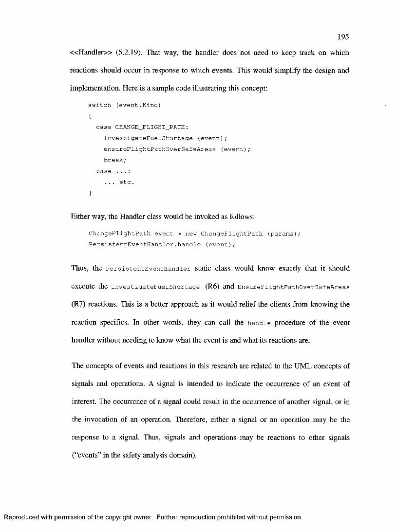
195
« H a n d le r » (5.2.19). That way, the handler does not need to keep track on which
reactions should occur in response to which events. This would simplify the design and
implementation. Here is a sample code illustrating this concept:
switch (event.Kind){
case CHANGE_FLIGHT_PATH:investigateFuelShortage (event); ensureFlightPathOverSafeAreas (event); break;
case . . . :... etc.
}
Either way, the Handler class would be invoked as follows:
ChangeFlightPath event = new ChangeFlightPath (params); PersistentEventHandler.handle (event);
Thus, the PersistentEventHandler static class would know exactly that it should
execute the InvestigateFuelShortage (R6) and EnsureFlightPathOverSafeAreas
(R7) reactions. This is a better approach as it would relief the clients from knowing the
reaction specifics. In other words, they can call the handle procedure of the event
handler without needing to know what the event is and what its reactions are.
The concepts of events and reactions in this research are related to the UML concepts of
signals and operations. A signal is intended to indicate the occurrence of an event of
interest. The occurrence of a signal could result in the occurrence of another signal, or in
the invocation of an operation. Therefore, either a signal or an operation may be the
response to a signal. Thus, signals and operations may be reactions to other signals
(“events” in the safety analysis domain).
Reproduced with permission of the copyright owner. Further reproduction prohibited without permission.
196
In summary, structuring and interpreting events and reaction is an implementation detail
rather than a significant design decision. Therefore, it will not be pursued any further in
this case study.
7.6 Design Analysis
Now that NavigationControllerSubsystem is designed according to the functional and
safety requirements, the design model is analysed according to the UML profile’s usage
scenarios identified in section 2.4. This section will illustrate the usefulness of modeling
safety information in the UML model using the proposed UML profile.
7.6.1 USAGE 1: Provide Safety Requirements
Safety requirements are provided by the safety and airworthiness engineers. In this case
study, the safety requirements resulted from the safety assessment performed in section
7.4, and the safety requirements were listed in section 7.4.5.
Two general requirements were specified in the class diagram for
NavigationControllerSubsystem in Figure 15 (see the top of the diagram). One of
them was a functional requirement, which indicated that the class diagram must fulfill all
FREQ requirements of the subsystem. The second one was a safety requirement, which
indicated that the class diagram must fulfill all SREQ requirements of the subsystem. To
ensure that every functional and safety requirement is addressed by at least one class, one
needs to ensure that every functional and safety requirement is referenced by at least one
class using an appropriate stereotype and its tagged values. The « R a t io n a le » (5.2.14)
Reproduced with permission of the copyright owner. Further reproduction prohibited without permission.

197
stereotype is the most common for such usage. This is a step towards ensuring that the
diagram fulfills those two high-level diagram requirements.
In addition, safety (and functional) requirements were referenced in the UML model
using the « R a t io n a le » (5.2.14) stereotype. Each model element that implemented at
least one safety (or functional) requirement was stereotyped with « R a t io n a le » (5.2.14).
Thus, the design was explicitly and precisely related to the safety requirements. This had
several advantages. One particular advantage that is relevant for this usage scenario is
that software engineers better consider safety requirements if they have to explicitly
relate the design model elements to them. This improves the communication between
software and airworthiness/safety engineers because software engineers are now better
able to relate the safety requirements to their software designs.
7.6.2 USAGE 2: Design Safety Requirements in Systems
Safety requirements were decomposed into events and reactions in section 7.5, which
helped design the safety requirements in the software. Event handlers, which perform
reactions to events, were designed and stereotyped with « H a n d le r » (5.2.19). When
events and reactions were modeled, either as a class or as an operation, they were
stereotyped with « E v e n t » (5.2.15) and « R e a c t io n » (5.2.16), respectively.
As a result of decomposing safety requirements into events and reactions, designing
safety requirements in the system reduces to ensuring that safety-related events are
detected and that the relevant reactions are properly executed. The events are listed and
described in section 7.5.2, and the reactions are listed and described in section 7.5.3. This
can be ensured by analysing event handling classes in Figure 15, which were stereotyped
Reproduced with permission of the copyright owner. Further reproduction prohibited without permission.

198
with « H a n d le r » (5.2.19), and ensuring that the “HandleableEvent” tagged values
include all previously identified safety-related events. In addition, it must be ensured that
all previously identified safety-related reactions are included in the “PerformedReaction”
tagged values, and that all such reactions are properly executed in response to the events
that trigger them. This helps ensure that all previously identified safety requirements are
accounted for in the design.
All classes that implement safety requirements are stereotyped with « R a t io n a le »
(5.2.14) and their “Reference” tagged values explicitly identify all the requirements that
they implement. Therefore, another way to ensure that the safety requirements are
accounted for in the design is to analyse the UML model and identify all « R a t io n a le »
(5.2.14) stereotypes. Then, their “Reference” tagged values are analysed to ensure that
every safety requirement is referenced by at least one class. A class references a safety
requirement if it implements it or at least helps implement it.
One particular use of the « R a t io n a le » (5.2.14) stereotype and its “Reference” tagged
value is to associate reactions to the safety requirements that they implement. This is
evident in Figure 14 as each modeled reaction is stereotyped with « R a t io n a le » (5.2.14)
to identify the safety requirements that it implements.
Since this is a highly-safety critical subsystem that has almost as many safety
requirements as functional requirements, safety-monitoring is emphasized. Safety
monitors are needed to design the safety requirements in the software. Thus, that
subsystem has several safety monitors, one for each subsystem on which it depends and
one for itself. The monitors can be identified by analysing the model and identifying all
Reproduced with permission of the copyright owner. Further reproduction prohibited without permission.

199
classes that are stereotyped with « M o n i to r » (5.2.20). Each monitor class explicitly
identifies what it monitors through the “MonitoredEntity” tagged value. Therefore,
NavigationControllerSubsystem will be able to track subsystem and class failures and
ensure that this does not cause any safety hazards. In fact, once a monitor detects an event
of interest, it notifies an appropriate event handler, which is stereotyped with
« H a n d le r » (5.2.19) itself.
The monitors were designed to detect the safety-critical events of interest to the safety
requirements. Once such an event is detected, the appropriate event handler is notified.
Once notified, the event handler executes the corresponding reaction for each event. The
reactions are intended to alleviate the safety hazards introduced by each event, which is
indicated by stereotyping each reaction with « R e a c t io n » (5.2.16) and setting its
“EffectOnSafetyDirection” tagged value to “Positive”. The safety monitoring classes,
which are stereotyped with « M o n i to r » (5.2.20) in the design are
WingsAndEnginesMonitor, NavigationDatabaseMonitor, NavigationMonitor, and
ControiierMonitorAndHandier. The event handlers, stereotyped with « H a n d le r »
(5.2.19) in the design are ExternalSubsystemsEventHandler and
ControiierMonitorAndHandier.
7.6.3 USAGE 3: Justify Design Decisions
Justifying design decisions is captured in the “Explanation” tagged value of the
« R a tio n a le » (5.2.14) stereotype. In this case study, a detailed explanation on how the
class implements each safety requirement, and often even functional requirement,
Reproduced with permission of the copyright owner. Further reproduction prohibited without permission.
200
assigned to it was discussed. This explanation was presented in section 7.5.5 and each
occurrence was explicitly identified as the value of an “Explanation” tagged value.
7.6.4 USAGE 4: Monitor Safety
There are many approaches to monitoring the design and ensuring that it fulfills safety
requirements. One way is to ensure that each safety requirement has design elements
traceable to it. This case study has used the « R a t io n a le » (5.2.14) stereotype to trace
design elements to safety requirements and provide justifications for this. The following
search query can be executed to determine which model elements. Including classes and
reactions, are traceable to (e.g. implement) safety requirements:
SEARCH FOR all model elements STEREOTYPED WITH (<<Rationale»)
The results can be analysed to determine how safety requirements were designed into the
system in USAGE 2, and the “Explanation” tagged value of the « R a t io n a le » (5.2.14)
stereotype can be read to determine the justifications, performed in USAGE 3, for the
design decisions performed in USAGE 2.
Executing this search query and then sorting the results per software requirement (i.e.
according to the “Reference” tagged value of the « R a t io n a le » stereotype) tells us
which classes and reactions implement each safety requirement. Notice that we do not
have events stereotyped with « R a t io n a le » (5.2.14) because they do not contain
executable code that implements safety requirements. The results (classes and reactions)
of the above query for each safety requirement are:
SREQ 1 WingsAndEnginesMonitor, ExternalSubsystemsEventHandler, EnableController (R3), DisableController (R4)
Reproduced with permission of the copyright owner. Further reproduction prohibited without permission.

201
SREQ 2 Controller, SafePointDeterminator,EnsureFlightPathsOverSafeAreas (R7)
SREQ 3 Controller, SafePointDeterminator,PathProjector, EnsureFlightPathsOverSafeAreas (R7)
SREQ 4 ControiierMonitorAndHandier, InvestigateFuelShortage (R6),RaiseFuelShortageExpectedAlert (R ll) , HideFuelShortageExpectedAlert (R12)
SREQ 5 ControiierMonitorAndHandier, RaiseSubsystemFailureAlert(R9),HideSubsystemFailureAlert (RIO).
SREQ 6 WingsAndEnginesMonitor, NavigationDatabaseMonitor,NavigationMonitor, ExternalSubsystemsEventHandler, EnableController (R3), DisableController (R4),RaiseSubsystemFailureAlert (R9), HideSubsystemFailureAlert (RIO)
SREQ 7 NavigationMonitor, ExternalSubsystemsEventHandler,ControiierMonitorAndHandier, and RequirePilotConfirmation (R8)
Furthermore, monitoring safety includes ensuring that each event that can have negative
effect on safety has one or more appropriate reactions that have a positive effect on
safety. This basically means that all hazards caused by events must be treated, and
technically removed, by reactions. Thus, each class stereotyped with « E v e n t » (5.2.15)
must be referenced at least once by a “ConsequenceOf ’ tagged value of a « R e a c t io n »
(5.2.16) stereotype of some class. In this case study, this was presented in sections 7.5.4
and 7.5.4, specifically in Figure 14 and Table 5, respectively.
Furthermore, one must ensure that all the safety-related events are detectable by
monitors. This is ensured through the “DetectableEvent” tagged value of the
« M o n i to r » (5.2.20) stereotype. Notice that a monitor can recognize events, but it does
not know which reactions may execute in response to each event. In fact, this is the
responsibility of an event handler. The following search query can be executed to obtain
a list of monitors:
SEARCH FOR all model elements STEREOTYPED WITH («Monitor»)
Reproduced with permission of the copyright owner. Further reproduction prohibited without permission.

202
Executing this query on the design in Figure 15 gives the following result:
ControiierMonitorAndHandier, WingsAndEnginesMonitor, NavigationDatabase
Monitor, and NavigationMonitor.
Then, looking into the “DetectableEvent” tagged value of the « M o n i to r » (5.2.20)
stereotype for each of the classes in the result above tells us which events are detected by
the identified monitors. This tells us whether all events of interest are detectable (i.e. the
design of monitors is complete) or not.
In addition, events detected by monitors must be handled by event handlers. The
“EventHandler” tagged value of the « M o n i to r » (5.2.20) stereotype for each monitor
class identifies the classes that the monitor notifies when any of the events represented by
the “DetectableEvent” tagged value occurs.
This case study contained two event handlers, each of which explicitly specifies the
events it can handle and the reactions that it performs in response to those events. This
information was presented in the “HandleableEvent” and “PerformedReaction” tagged
values, respectively, of the « H a n d le r » (5.2.19) stereotype. A list of event handlers can
be obtained by executing the following search query:
SEARCH FOR all model elements STEREOTYPED WITH («Handler»)
Executing this search query on the design model in Figure 15 gives the following result:
ExternalSubsystemsEventHandler, and ControiierMonitorAndHandier.
Then, one needs to ensure that the “HandleableEvent” and “PerformedReaction” of the
« H a n d le r » (5.2.19) stereotype for all handler classes reference all the previously
Reproduced with permission of the copyright owner. Further reproduction prohibited without permission.

203
determined events and their reactions. This tells us whether all safety-related events of
interest are properly handled, through the execution of appropriate reactions, or not.
7.6.5 USAGE 5: Get Safety Information
Safety information that is required to prove compliance with airworthiness requirements
includes ensuring that each safety requirement is implemented. This was discussed in
sections 7.6.1 - 7.6.4.
In addition, safety information that is required by the certification authorities also
includes determining hardware/software interfaces as explained in section 6.2.1. This can
be obtained by executing the search query described in section 6.2.1. The search query is:
SEARCH FOR all model elements STEREOTYPED WITH («Interface»
WITH TAGGED VALUE (IsBetweenHardwareAndSoftware = true))
Executing it on NavigationControllerSubsystem (section 7.5.5) gives:
WingsAndEnginesInterface, and Navigationlnterface.
Furthermore, the certification authorities require that software levels be specified and
submitted as explained in section 6.2.2. This can be obtained by executing the search
query in section 6.2.2. This search query is:
SEARCH FOR all model elements STEREOTYPED WITH
(<<SafetyCritical>>)
Executing it on the system architecture in section 7.2 gives all the subsystems, namely:
Me chanicalSteeringWheelSubsystem, NavigationUserInterfaceSubsystem,
Reproduced with permission of the copyright owner. Further reproduction prohibited without permission.
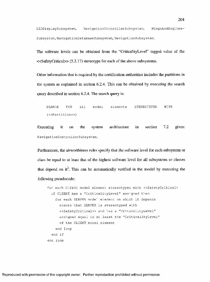
204
LEDDisplaySubsystem, NavigationControllerSubsystem, WingsAndEngines-
Subsystem, NavigationDatabaseSubsystem, NavigationSubsystem.
The software levels can be obtained from the “CriticalityLevel” tagged value of the
« S a fe ty C ritic a l» (5.2.17) stereotype for each of the above subsystems.
Other information that is required by the certification authorities includes the partitions in
the system as explained in section 6.2.4. This can be obtained by executing the search
query described in section 6.2.4. The search query is:
SEARCH FOR all model elements STEREOTYPED WITH
(<<Partition>>)
Executing it on the system architecture in section 7.2 gives:
NavigationControllerSubsystem.
Furthermore, the airworthiness rules specify that the software level for each subsystem or
class be equal to at least that of the highest software level for all subsystems or classes
that depend on it2. This can be automatically verified in the model by executing the
following pseudocode:
for each CLIENT model element stereotyped with <<SafetyCritical> if CLIENT has a "CriticalityLevel" assigned then
for each SERVER model element on which it depends ensure that SERVER is stereotyped with <<SafetyCritical>> and has a "CriticalityLevel" assigned equal to at least the "CriticalityLevel" of the CLIENT model element
end loop end if
end loop
Reproduced with permission of the copyright owner. Further reproduction prohibited without permission.
205
Moreover, the certification authorities require a list and description of all safety monitors.
The monitors and handlers were discussed in sections 7.6.2 and 7.6.4.
Reproduced with permission of the copyright owner. Further reproduction prohibited without permission.

206
8 CONCLUSION
This research has proposed a UML profile for developing software to be compliant with
the airworthiness standard, RTCA DO-178B [4], The profile was based on the safety-
related concepts that were extracted from the airworthiness standard as well as their
refined concepts. As a result, the UML extensions provided by this profile are a
consequence of the concepts emphasized by the airworthiness standard.
For example, the airworthiness standard emphasized traceability across requirements,
design, and source code. The proposed profile provides specific extensions to model
traceability of design elements to requirements, deviation of design elements from
original requirements, requirements in the UML model, justification of design and
implementation styles according to requirements, and partitioning of the architecture
according to the requirements. A detailed analysis on how the UML profile can be used
to fulfill each information requirement is presented in section 8.1.
Furthermore, this research has shown how a software model using an appropriate UML
profile can be used to effectively generate airworthiness-related information. Such
information can be submitted to the certification authorities, or it can be used by the
airworthiness engineers to track how software evolves over the lifetime of a project from
an airworthiness point of view.
The profile’s completeness and usefulness was validated by performing a case study. An
aircraft’s navigation subsystem was defined and analysed by performing a safety
assessment. It was then modeled using the proposed UML profile. Analysing the model
Reproduced with permission of the copyright owner. Further reproduction prohibited without permission.

207
showed that the UML profile effectively supported the previously identified usage
scenarios for safety information. In addition, it is effective in tracing model elements to
safety requirements and in automatically generating certification information from a
UML model.
To achieve the results presented above, this research had to define the used safety-related
concepts precisely. The original safety-related concepts that were extracted from the
airworthiness standard were refined into concepts that better grouped related concepts.
Furthermore, each safety related concept was described in detail, and attributes were
defined to describe the various aspects and dimensions of each concept. A conceptual
model (class diagram) was also defined and presented, which precisely defined the
relationships across safety-related concepts and modeled them as associations and
inheritance relationships. Furthermore, the profile precisely defined the tagged values for
each stereotype including its type and multiplicity, and mapped each stereotype and its
tagged values to the refined concepts and their attributes and relationships.
It is also important to note that this UML profile builds on top of existing UML model
diagrams within a project. In other words, using this UML profile does not require the
software engineers to create new diagrams but they must stereotype model elements
accordingly. Therefore, the amount of effort involved in using this profile is minimal.
This also contribute towards improving communication between safety and airworthiness
engineers on the one hand, and software engineers on the other hand.
Reproduced with permission of the copyright owner. Further reproduction prohibited without permission.

208
8.1 Fulfilling Requirements
The proposed UML profile was defined based on the refined safety-related concepts
specified in section 3.2. As section 5 illustrates, there exists a stereotype for each of the
refined concepts. Therefore, the proposed UML profile is able to model all the refined
concepts. Table 6 illustrates how each information requirement is fulfilled by the
proposed UML profile.
IREQ# How to Fulfill the Information RequirementIREQ 1 Use «SafetyContext» (5.2.1) stereotypeIREQ 2 Use «ReliabilityContext» (5.2.2) stereotypeIREQ 3 Use «IntegrityContext» (5.2.3) stereotypeIREQ 4 Use «PerformanceContext» (5.2.4) stereotypeIREQ 5 Use «ConcurrencyContext» (5.2.5) stereotypeIREQ 6 Use «CertificationContext» (5.2.6) stereotypeIREQ 7 Use «ConfigurationContext» (5.2.8) stereotypeIREQ 8 Use «DesignContext» (5.2.7) stereotypeIREQ 9 Use «R equirem ent» (5.2.9) stereotype and its “Kind” and “Specification” tagsIREQ 10 Use «R equirem ent» (5.2.9) stereotype and its “OfGoal” tagIREQ 11 Use «D ev iation» (5.2.10) stereotypeIREQ 12 Use «ImplementationStyle» (5.2.11) stereotype and its “Kind” tagIREQ 13 Use «BehaviouralStyle» (5.2.12) stereotype with its “Kind” tag equal to “Time-
Related”IREQ 14 Use «BehaviouralStyle» (5.2.12) stereotype with its “Kind” tag equal to “State-
Related”IREQ 15 Use « N a tu re » (5.2.13) stereotype and its “Reference” and “Explanation” tags with
its “Kind” tag equal to “COTS”IREQ 16 Use « N a tu re » (5.2.13) stereotype and its “Reference” and “Explanation” tags with
its “Kind” tag equal to “Previously Developed”IREQ 17 Use « N a tu re » (5.2.13) stereotype and its “Reference” and “Explanation” tags with
its “Kind” tag equal to “Deactivated”IREQ 18 Use «R ationale» (5.2.14) stereotypeIREQ 19 Use «R ationale» (5.2.14) stereotype and its “Reference” and “Explanation” tagsIREQ 20 Use « E v e n t» (5.2.15) stereotypeIREQ 21 Use « E v e n t» (5.2.15) stereotype and its “EffectOnSafetyDirection” and
“EffectOnSafety Value” tags
Reproduced with permission of the copyright owner. Further reproduction prohibited without permission.
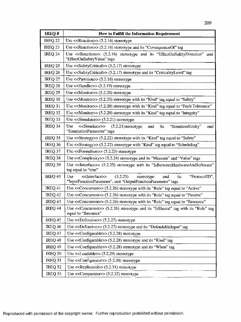
209
IREQ# How to Fulfill the Information RequirementIREQ 22 Use « R eac tio n » (5.2.16) stereotypeIREQ 23 Use « R eac tio n » (5.2.16) stereotype and its “ConsequenceOf” tagIREQ 24 Use « R eac tio n » (5.2.16) stereotype and its “EffectOnSafetyDirection” and
“EffectOnSafetyValue” tagsIREQ 25 Use «SafetyCritical» (5.2.17) stereotypeIREQ 26 Use «SafetyCritical» (5.2.17) stereotype and its “CriticalityLevel” tagIREQ 27 Use « P artitio n » (5.2.18) stereotypeIREQ 28 Use « H a n d le r» (5.2.19) stereotypeIREQ 29 Use « M o n ito r» (5.2.20) stereotypeIREQ 30 Use « M o n ito r» (5.2.20) stereotype with its “Kind” tag equal to “Safety”IREQ 31 Use « M o n ito r» (5.2.20) stereotype with its “Kind” tag equal to “Fault Tolerance”IREQ 32 Use « M o n ito r» (5.2.20) stereotype with its “Kind” tag equal to “Integrity”IREQ 33 Use «S im u la to r» (5.2.21) stereotypeIREQ 34 Use «S im u la to r» (5.2.21)stereotype and its “SimulatedEntity” and
“SimulationParameter” tagsIREQ 35 Use « S tra teg y » (5.2.22) stereotype with its “Kind” tag equal to “Safety”IREQ 36 Use « S tra teg y » (5.2.22) stereotype with “Kind” tag equal to “Scheduling”IREQ 37 Use «Form alism » (5.2.23) stereotypeIREQ 38 Use «C om plexity» (5.2.24) stereotype and its “Measure” and “Value” tagsIREQ 39 Use « In te rface» (5.2.25) stereotype with its “IsBetweenHardwareAndSoftware”
tag equal to “true”IREQ 40 Use « In te rface» (5.2.25) stereotype and its “ProtocolID”,
“InputFunctionParameter”, and “OutputFunctionParameter” tagsIREQ 41 Use «C oncurrent» (5.2.26) stereotype with its “Role” tag equal to “Active”IREQ 42 Use «C oncurrent» (5.2.26) stereotype with its “Role” tag equal to “Passive”IREQ 43 Use «C oncurrent» (5.2.26) stereotype with its “Role” tag equal to “Resource”IREQ 44 Use «C oncurren t» (5.2.26) stereotype and its “IsShared” tag with its “Role” tag
equal to “Resource”IREQ 45 Use «D efensive» (5.2.27) stereotypeIREQ 46 Use «D efensive» (5.2.27) stereotype and its “Defendablelnput” tagIREQ 47 Use «C onfigurable» (5.2.28) stereotypeIREQ 48 Use «C onfigurable» (5.2.28) stereotype and its “Kind” tagIREQ 49 Use «Configurable» (5.2.28) stereotype and its “When” tagIREQ 50 Use « L o adab le» (5.2.29) stereotypeIREQ 51 Use «Configurator» (5.2.30) stereotypeIREQ 52 Use «R eplicated» (5.2.31) stereotypeIREQ 53 Use «C om parator» (5.2.32) stereotype
Reproduced with permission of the copyright owner. Further reproduction prohibited without permission.

210
IREQ# How to Fulfill the Information RequirementIREQ 54 Use «C om parator» (5.2.32) stereotype and its “PolicyParameter” tag
Total All 54 information requirements are fulfilled
Table 6: Using the proposed UML profile to fulfill the information requirements.
8.2 Open Issues and Future Work
This research has defined a software safety UML profile and demonstrated how it can
help solve the identified challenges. Numerous examples of its usage have been presented
(section 5.3). Furthermore, the profile has been applied in a case study (section 7)
involving an aircraft navigation controller system - a key software element in every
aircraft. Future work could include applying the profile for other systems in diverse
organizations, and then soliciting the engineers participating in those projects to identify
the strengths and weaknesses of this profile. Such solicitations can be used to generate
qualitative and quantitative results in an approach similar to the one used in [46],
This research has focused on modeling safety information in class diagrams. It
demonstrated how the proposed UML profile’s stereotypes and tagged values can be used
to model information in class diagrams. There was little discussion of other types of
diagrams, such as dynamic diagrams including object diagrams and statecharts. This has
been left for future work. However, the proposed UML profile should be easily
transferable for dynamic diagrams.
The proposed UML profile lists the UML meta classes on which each stereotype may be
applied (section 5.1). This list may not necessarily be sufficient for all usages. More
specifically, certain applications of this profile may determine that it is useful to apply
Reproduced with permission of the copyright owner. Further reproduction prohibited without permission.

211
certain stereotypes on UML meta classes that are not listed here. Nevertheless, this will
form the path in which this profile can evolve in the future.
The refined safety-related concepts (section 3.2), which formed the basis of the UML
profile, are mostly based on the general safety-related concepts identified in the
airworthiness standard [4]. A standard is normally written in a high-level language as to
not restrict the developers following it. Different projects have different airworthiness
requirements and/or technical solutions to airworthiness requirements, and hence may
have additional refined concepts. This is because UML models can be used as an
interface between safety engineers and software developers. This may introduce the need
for additional profile stereotypes and tagged values.
Although airworthiness is a subset of safety, it is specific to the aerospace industry. Many
other industries exist where safety-critical software is used such as the medical, nuclear,
transport, and defence industries. This research was based on the airworthiness standard,
and therefore is intended to meet requirements of the aerospace industry. Those
requirements may or may not be sufficient in other industries that use different safety-
related standards. However, an attempt has been made in this research to generalize
results as much as possible without compromising the ability to model specific
airworthiness concepts and needs. Therefore, this UML profile should be easily tailorable
and applicable to other industries.
It was initially thought that it would be best to propose a UML profile that would be as
compliant as possible with existing OMG UML profiles. However, it was found that it
was better to define concepts for which similar stereotypes existed in other profiles (e.g.
Reproduced with permission of the copyright owner. Further reproduction prohibited without permission.

212
« R eq u irem en t» (5.2.9) stereotype is similar to the « Q o S C o n s tra in t» and its
subtypes in the QoS and FT OMG UML profile [5]). This redefinition allowed this
profile to be simple, clear, and most importantly self-contained and independent of other
existing profiles. This is important from a maintainability point of view because we may
not necessarily need to modify this profile if other OMG UML profiles are revised and
newer versions are available.
While some of its stereotypes and tagged values can be used to model safety-related
information for systems, this UML profile has focused on modeling them for software.
This is jusitified by the fact that the airworthiness standard [4] focuses on software itself.
Nevertheless, it may be useful to model such information for systems in future work. In
that regard, the OMG System Modeling Language [47], which resuses and extends a
subset of UML [30] to model systems, may be helpful. In fact, it may be merged with
UML to constitute the base modeling language for a new systems and software UML
profile.
Certain extension mechanisms that describe the code were added. Examples of these
include using «Im plem entationStyle» (5.2.11) to identify recursive code, or code that
dynamically allocates memory. Another example is using the « C o m p le x ity » (5.2.24)
stereotype to identify constraints on the level of code nesting. While they were provided
here for completeness and their need in software certification, some of them are generally
better addressed by a software code analysis tool that could parse software code, analyse
it, and extract this information. The later approach would provide more complete and
accurate results, and it would relieve the developers from maintaining this information in
the model. Therefore, it may be more appropriate to use such stereotypes and tagged
Reproduced with permission of the copyright owner. Further reproduction prohibited without permission.

213
values as placeholders for data entered by software analysis tools. This UML profile does
not specify the source of the information entered by the software engineers. Thus, a
possible future extension could explicitly address this distinction and potentially provide
two different values for each piece of information - a specified value, which is entered by
the engineers to indicate requirements, and an analysis value, which is entered by a tool
to indicate a predicted or measured value. Then, a tool can compare those two sets of
values to detect violations.
Most enumeration tagged values for some stereotypes were left open for extension by the
users of this profile. This recognizes the fact that each software application may have
specific needs or usages whose level of detail that is not addressed here. Therefore, this
gives flexibility in a seemingly open UML profile. However, this UML profile lists
sample values for each enumeration type that are deemed most useful. Thus, users o f this
UML profile do not need to do extra work in defining the enumeration values unless they
truly need to.
Search queries on UML models were used to illustrate how certification-relevant
information can be extracted from a UML model. Those search queries were specified in
a Structured Query Language (SQL)-like textual language. This could be refined and
eventually lead into the development of an SQL-variant language that is used specifically
to search and query UML models. Such a language should be defined such as it is
independent of the UML profiles used.
Alternatively, the integration of EMF and OCL seems to be a promising integration of
technologies to query UML models. The current state of this technology does not support
Reproduced with permission of the copyright owner. Further reproduction prohibited without permission.

214
querying UML models for model elements according to criteria specifying the
stereotypes and tagged values applied on the model elements. However, EMF and OCL
should be easily extensible to support this because it already supports some form of
querying UML models and class objects. Such an extension would be supportive of this
UML profile as it will allow developers to dynamically query this information.
Reproduced with permission of the copyright owner. Further reproduction prohibited without permission.

215
9 SUMMARY
This research has investigated the relationship between UML and software safety. The
airworthiness standard [4] is widely considered as the de-facto safety standard in the
aerospace industry. Therefore, modeling software that has to be developed in an
environment satisfying the airworthiness standard was considered. Since UML has
become the de-facto software modeling language, it was fitting to define a UML profile
for modeling safety-critical software. Therefore, even high-level requirements were
identified for a UML profile to be able to effectively model safety-critical software
developed under the airworthiness standard.
The airworthiness standard was analysed to determine safety-related concepts of interest.
A list of 65 safety-related concepts was formed, and the concepts were categorized in
eight different but related categories: safety, reliability, integrity, performance,
concurrency, certification, design, and configuration.
Given the language difference between standards and UML modeling techniques, the 65
safety-related concepts were refined into 27 concepts that were more appropriate from a
software modeling perspective. This refined list of concepts removed duplication across
similar concepts, and it defined additional concepts that were not covered by the original
65. The 27 refined safety-related concepts were explained in detail and their inter-concept
relationships were formalized through a conceptual model. This allowed us to define 54
information requirements for a candidate UML profile to model those concepts. Those 54
information requirements were traced back to the original 7 high-level concepts.
Reproduced with permission of the copyright owner. Further reproduction prohibited without permission.

216
After analyzing several existing UML profiles and concluding that they did not fulfill an
acceptable percentage of the 54 information requirements, a UML profile was proposed.
The profile, composed of 32 stereotypes and their tagged values, was presented in detail.
Several examples of using the profile were presented and explained in detail. The profile
fulfilled the 54 information requirements and guidance was presented on how it can be
used to fulfill each one of the information requirements.
One specific usage of the profile was the ability to automatically provide airworthiness
and certification information from a UML model. Therefore, examples of such usage
were presented. Each example identified a specific need from the airworthiness standard,
and then it presented search queries that a UML modeling tool can execute on a model
employing the proposed profile to automatically generate the required information. This
is handy for submitting software-related information to the certification authority as well
as continuous project monitoring and control by managers and airworthiness engineers
that are likely to be less experienced with software.
The UML profile was validated by using it to design and analyse an aircraft’s navigation
controller subsystem - a key element in every aircraft. The overall system’s architecture
was presented and explained, and then the navigation controller’s subsystem’s functional
requirements were defined. Then, a safety assessment using the AEA, FMEA, HAZOP,
and LA methods was performed, which identified 11 safety hazards relevant to the
subsystem under study. Those resulted in 7 safety requirements for the subsystem’s
software. The subsystem was then designed using the UML profile, and an analysis of the
model was performed. The analysis showed that the resultant UML model contained
Reproduced with permission of the copyright owner. Further reproduction prohibited without permission.

217
information on how the model elements were traceable to the safety requirements, as well
as additional information relevant to the certification authorities.
Future work in this area could include using the profile in real-life projects and soliciting
participating stakeholders for improvement information.
Reproduced with permission of the copyright owner. Further reproduction prohibited without permission.

218
REFERENCES
[1] Nancy G. Leveson, Safeware - System Safety and Computers, Addison-Wesley, 1995
[2] Tom Pender, UML Bible, Wiley, 2003
[3] A. Kleppe, J. Warmer and W. Bast, MDA Explained: The Model Driven Architecture
- Practice and Promise, Addison-Wesley, First Edition, 2003
[4] Radio Technical Commission for Aeronautics (RTCA) Inc., DO-178B - Software
Considerations in Airborne Systems and Equipment Certification, December 1992
[5] Object Management Group (OMG) Inc., UML Profile fo r Modeling Quality o f Service
and Fault Tolerance Characteristics and Mechanisms, http://www.omg.org/docs/ptc/05-
05-02.pdf, May 2005
[6] Object Management Group (OMG) Inc., UML Profile fo r Schedulability,
Performance, and Time Specification, http://www.omg.org/docs/formal/05-01-02.pdf,
January 2005
[7] Hassan Gomaa, Designing Concurrent, Distributed, and Real-Time Applications with
UML, Addison-Wesley, 2000
[8] RTC Magazine, Certification Requirements fo r Safety-Critical Software,
http://www.rtcmagazine.com/home/article.php?id=100010, June 2004
[9] Debra S. Hermann, Software Safety and Reliability, IEEE Computer Society, 1999
Reproduced with permission of the copyright owner. Further reproduction prohibited without permission.
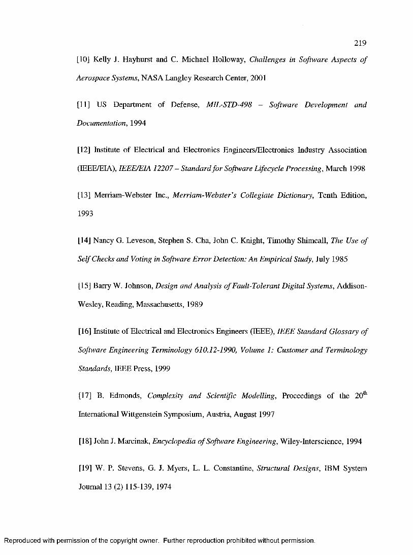
219
[10] Kelly J. Hayhurst and C. Michael Holloway, Challenges in Software Aspects o f
Aerospace Systems, NASA Langley Research Center, 2001
[11] US Department of Defense, MIL-STD-498 - Software Development and
Documentation, 1994
[12] Institute of Electrical and Electronics Engineers/Electronics Industry Association
(IEEE/EIA), IEEE/EIA 12207 - Standard fo r Software Lifecycle Processing, March 1998
[13] Merriam-Webster Inc., Merriam-Webster’s Collegiate Dictionary, Tenth Edition,
1993
[14] Nancy G. Leveson, Stephen S. Cha, John C. Knight, Timothy Shimeall, The Use o f
Self Checks and Voting in Software Error Detection: An Empirical Study, July 1985
[15] Barry W. Johnson, Design and Analysis o f Fault-Tolerant Digital Systems, Addison-
Wesley, Reading, Massachusetts, 1989
[16] Institute of Electrical and Electronics Engineers (IEEE), IEEE Standard Glossary o f
Software Engineering Terminology 610.12-1990, Volume 1: Customer and Terminology
Standards, IEEE Press, 1999
[17] B. Edmonds, Complexity and Scientific Modelling, Proceedings of the 20th
International Wittgenstein Symposium, Austria, August 1997
[18] John J. Marcinak, Encyclopedia o f Software Engineering, Wiley-Interscience, 1994
[19] W. P. Stevens, G. J. Myers, L. L. Constantine, Structural Designs, IBM System
Journal 13 (2) 115-139, 1974
Reproduced with permission of the copyright owner. Further reproduction prohibited without permission.

220
[20] R. W. Jensen, C. C. Tonies, Software Engineering, Prentice Hall, 1979
[21] G. J. Myers, Software Reliability Principles and Practices, John Wiley & Sons, 1976
[22] Bertrand Meyer, Object-Oriented Software Construction, Prentice Hall, Second
Edition, 1997
[23] J. B. Wordsworth, The Best from Formal Methods, Information and Software
Technology 41(14), pp. 1027-1032, November 1999
[24] International Electrotechnical Commission (TEC), IEC 61508 - Functional Safety o f
Electrical/Electronic/Programmable Electronic Safety-Related Systems, December 1998
[25] US Department of Defense, MIL-STD-1553B — Aircraft Internal Time-Division
Command/Response Multiplex Data Bus, 1986
[26] Jean-Noel Meunier, Frank Lippert, and Ravi Jadhav, RT Modeling with UML fo r
Safety Critical Applications - the H1DOORS Project Example, 2003
[27] Jan Jtiijens, Developing Safety-Critical Systems with UML, 2003
[28] Kai T. Hansen and Ingolf Gullesen, Utilizing UML and Patterns fo r Safety Critical
Systems, 2002
[29] Object Management Group (OMG) Inc., Unified Modeling Language:
Infrastructure, http://www.omg.org/docs/formal/05-07-05.pdf, March 2006
[30] Object Management Group (OMG) Inc., Unified Modeling Language:
Superstructure, http://www.omg.org/docs/formal/05-07-04.pdf, August 2005
Reproduced with permission of the copyright owner. Further reproduction prohibited without permission.

221
[31] ARTiSAN Software Inc., ARTiSAN Studio,
http://www.artisansw.com/pdf/product_sheets/studio.pdf, September 2006
[32] International Business Machines (IBM) Software, Rational Software Architect,
http://www-306.ibm.com/software/awdtools/architect/swarchitect/, August 2006
[33] Telelogic, Rhapsody, http://www.ilogix.com/sublevel.aspx?id=53, October 2006
[34] Frank Budinsky, David Steinberg, Ed Merks, Raymond Ellersick, Timothy J. Grose,
Eclipse Modeling Framework: A Developer's Guide, Addison-Wesley, August 2003
[35] Object Management Group (OMG) Inc., Object Constraint Language,
http://www.omg.org/docs/formal/06-05-01.pdf, May 2006
[36] Object Management Group (OMG) Inc., MOF 2.0/XMIMapping Specification v2.1,
http://www.omg.org/docs/formal/05-09-01.pdf, September 2005
[37] World Wide Web Consortium, The Extensible Stylesheet Language Family (XSL),
http://www.w3.org/Style/XSL/, September 2005
[38] Daniel P. Friedman, Mitchell Wand, Christopher T. Haynes, Essentials o f
Programming Languages, Second Edition, The MIT Press, January 2001
[39] International Organization for Standardization/ International Electrotechnical
Commission, ISO/IEC 14977:1996 - Information Technology - Syntactic Metalanguage
- Extended BNF, First Edition, 1996
Reproduced with permission of the copyright owner. Further reproduction prohibited without permission.

222
[40] International Organization for Standardization/ International Electrotechnical
Commission, ISO/IEC 8652:1995 - Information Technology - Programming Languages
-A d a , 1995
[41] E. D. Lazowska, J. Zahoijan, G. S. Graham, and K. Sevcik, Quantitative System
Performance, Prentice Hall, 1984
[42] Juoko Suokas, The Role o f Safety Analysis in Accident Prevention, 1988
[43] D. H. Stamatis, Failure Mode and Effect Analysis: FMEA From Theory to
Execution, Second Edition, 2003
[44] Trevor Kletz, Lessons from Disaster, Gulf Publishing Company, Houston, 1993
[45] William B. Noble, Developing safe software fo r critical airborne applications, IEEE
6th Digital Conference, Baltimore, December 1984
[46] Bente Anda, Kai Hansen, Ingolf Gullesen, and Hanne Kristin Thorsen, Experiences
from Introducing UML-based Development in a Large Safety-Critical Project, 2004
[47] Object Management Group (OMG) Inc., Systems Modeling Language,
http://www.omg.org/cgi-bin/apps/doc7ptc/06-05-04.pdf, May 2006
Reproduced with permission of the copyright owner. Further reproduction prohibited without permission.

223
Appendix A Examples of Safety/Risk Assessment Methods
Method Analyzed Subjects Output CommentsAction Error
Analysis (AEA)
Human-machine
interactions
Consequences of
actions that operators
perform at the wrong
time, or do not perform
when they should
Similar to FMEA but is
applied to steps in human
procedures rather than
hardware or components
Cause-
Consequence
Analysis (CCA)
Critical events Causes and
consequences of critical
events
Unlike fault trees, it
explicitly shows the
sequence of events.
Unlike event trees, it
allows the representation
of time delays, alternative
consequence paths, and
combination of events
Event Tree
Analysis (ETA)
Critical events Consequences of
critical events
Is a version of FTA that
is tailored to large and
complex systems. Breaks
large problems into
smaller ones to which
FTA may be applied
Failure Modes and
Effects Analysis
(FMEA)
Possible failures Probabilities of failures.
Overall probability that
the product will operate
without a failure for a
specific period of time
Reliability-oriented rather
than safety-oriented.
Emphasizes correct
functioning rather than
hazards and risks.
Concentrates on single
events of failures
Reproduced with permission of the copyright owner. Further reproduction prohibited without permission.

224
Method Analyzed Subjects Output CommentsFailure Modes,
Effects, and
Criticality
Analysis
(FMECA)
Possible failures Same as FMEA but it
includes the criticalities
of failures
Is an extended FMEA
that examines the
criticality of each event in
more detail. Concentrates
on single events of
failures
Fault Hazard
Analysis (FHA)
Possible failures
that may result in
accidents
Similar to FMEA or
FMECA, but it
considers a different
scope
Causes of failures are
considered over a wide
scope that even includes
human errors, procedural
deficiencies, and
environmental conditions.
Concentrates on single
events of failures that
may cause accidents
Fault Tree
Analysis (FTA)
Previously-
identified hazards
Causes of the
previously-identified
hazards, fault trees and
Boolean expressions
for them
Hazards should have
already been identified by
other methods. A popular
method but not scalable
to large and complex
systems. Considers
relationships across
events that cause hazards
Hazards and
Operability
Analysis
(HAZOP)
System design and
operating intentions
Possible deviations
from the design and
operating intentions,
and hazards that result
from them
Uses a qualitative
approach. Labour
intensive. Does not
require that the hazards
be previously identified
Interface Analyses
(IA)
Inter-component
interfaces
Connection failures that
can lead to failure
propagations
Similar to HAZOP but is
more general
Reproduced with permission of the copyright owner. Further reproduction prohibited without permission.

225
Method Analyzed Subjects Output CommentsManagement
Oversight and
Risk Tree Analysis
(MORT)
Managerial
functions, human
behaviour, and
environmental
factors
Problems, defects, and
oversights that create
hazards or prevent their
early identification by
poor planning,
inadequate operational
checks, or limited
information-exchange
within the organization.
Checklist-based
State Machine
Hazard Analysis
(SMHA)
Hazardous states in
software state
machines
Conditions that cause
the software to enter
the hazardous states
Intended for software.
Works on the model
rather than the design
itself
Table 7: Examples of safety or risk assessment methods.
Reproduced with permission of the copyright owner. Further reproduction prohibited without permission.

226
Appendix B Examples of Safety-Related Standards
Industry Owner StandardAerospace Radio Technical
Commission for
Aeronautics (RTCA)
DO-178B, Software Considerations in Airborne
Systems and Equipment Certification
European Space Agency
(ESA)
Set of Several Standards - ECSS-Q-OOA, ECSS-Q-
20A, ECSS-Q-30A, ECSS-Q-40A, ECSS-Q-80A,
ECSS-Q-80-2, ECSS-Q-80-3, ECSS-Q-80-4
National Aeronautics and
Space Administration
(NASA)
NASA-STD-8719.13A - Software Safety,
September 1997
National Aeronautics and
Space Administration
(NASA)
NASA-GB-1740.13-96 - NASA Guidebook for
Safety Critical Software - Analysis and
Development, September 1997
American Institute of
Aeronautics and
Astronautics (AIAA)
R-013-1992 - Recommended Practice: Software
Reliability, 1992
Biomedical International
Electrotechnical
Commission (IEC)
601-1-4(1996-06) - Medical Electrical Equipment
- Part 1: General Requirements for Safety - 4.
Collateral Standard: Programmable Electric
Medical Systems, June 1996
Defence U.S. Department of
Defense (DoD)
MIL-STD-882D - Standard Practice for System
Safety, February 2000
U.K. Ministry of Defence
(MoD)
DEF STAN 00-55 - Requirements for Safety
Related Software in Defence Equipment, August
1997
North Atlantic Treaty
Organization (NATO)
Commercial Off-the-Shelf (COTS) Software
Acquisition Guidelines and COTS Policy Issues,
January 1996
Reproduced with permission of the copyright owner. Further reproduction prohibited without permission.

227
Industry Owner StandardNuclear Power International
Electrotechnical
Commission (IEC)
61508:1986-09 - Software for Computers in Safety
Systems of Nuclear Power Stations, including the
First Supplement, 60880-1 (FDIS), 1977
Ontario Hydro Nuclear and
Atomic Energy Canada,
Ltd. (AECL)
CE-1001-STD - Standard for Software
Engineering of Safety Critical Software, January
1995
Transportation European Committee for
Electrotechnical
Standardisation
(CENELEC)
EN 50128:2001 - Railway Applications: Software
for Railway Control and Protection Systems
Motor Industry Software
Reliability Association
(MISRA)
Development Guidelines for Vehicle-Based
Software, November 2001
Society of Automotive
Engineers (SAE)
JA 1002 - Software Reliability Program Standard,
July 2004
Non-Industry
Specific
International
Electrotechnical
Commission (IEC)
61508-3:1998-12 - Functional Safety of
Electrical/Electronic/Programmable Electronic
Safety-Related Systems - Part 3: Software
Requirements, December 1998
International
Electrotechnical
Commission (IEC)
300-3-9:1995-12 - Dependability Management -
Part 3: Application Guide - Section 9: Risk
Analysis of Technological Systems, December
1995
International Organization
for Standardization (ISO)
15026:1998-04-29 - System and Software
Integrity Levels, April 1998
Institution of Electrical
Engineers (IEE)
Software Engineering Methods for Safe
Programmable Logic Controllers (SEMSPLC)
Guidelines - Safety-Related Application Software
for Programmable Logic Controllers, September
1996
Reproduced with permission of the copyright owner. Further reproduction prohibited without permission.

228
Industry Owner StandardInstitute of Electrical &
Electronic Engineers
(IEEE)
Std. 982.1-1989 and 982.2-1989 - Measures to
Produce Reliable Software
Institute of Electrical &
Electronic Engineers
(IEEE)
Std. 1228-1994 - Standard for Software Safety
Plans, 1994
Table 8: Some of the many safety-related standards that exist for several industries.
Reproduced with permission of the copyright owner. Further reproduction prohibited without permission.

Appendix C Concept Identification and Categorization from
the Airworthiness Standard
C.l Primarily Safety Concepts
Concept Description RTCA DO- 1788 Section
Failure Condition The effect that one or more failures cause on, or
contribute to, the aircraft and its occupants, directly or
indirectly, considering relevant adverse operational and
environmental conditions [4],
2.2
Failure Condition Failure conditions are categorized according to the 2.2
Category severity of their effects as defined in some standard [4], 2.2.1
Level of Confidence In the context of software safety, the level of confidence
is the extent of the assurance to which the software is
believed to exhibit the desired behaviour of safety, with
respect to the system in which it is deployed.
4.1
6.4
Loadable Software
Indicator
A hardware or software that is used to indicate the status
of the field-loadable software (see section C.l). This
indicator should be able to detect incorrect software
and/or hardware and/or aircraft combinations and should
provide protection appropriate to the failure condition of
the function [4],
2.5
Safeguard A technical contrivance to prevent accident [13]. 7.2.8
11.4
Safety Feature A prominent part or characteristic [13], which is
intended to increase the safety of the system.
4.4
11.1
Reproduced with permission of the copyright owner. Further reproduction prohibited without permission.
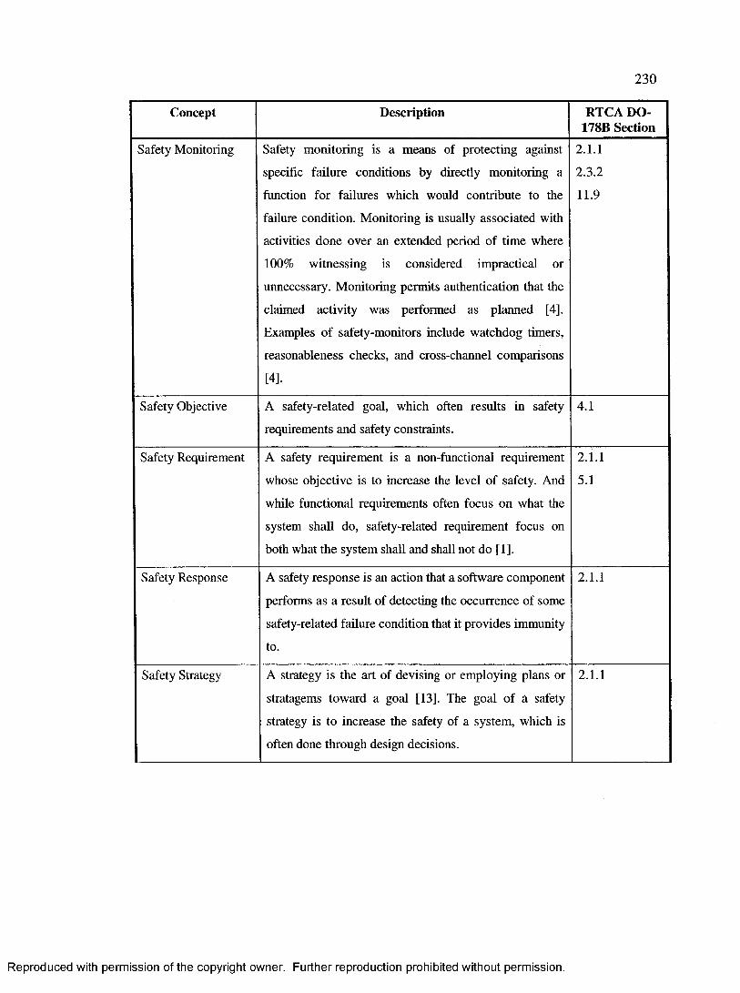
230
Concept Description RTCA DO- 178B Section
Safety Monitoring Safety monitoring is a means of protecting against
specific failure conditions by directly monitoring a
function for failures which would contribute to the
failure condition. Monitoring is usually associated with
activities done over an extended period of time where
100% witnessing is considered impractical or
unnecessary. Monitoring permits authentication that the
claimed activity was performed as planned [4],
Examples of safety-monitors include watchdog timers,
reasonableness checks, and cross-channel comparisons
[4].
2.1.1
2.3.2
11.9
Safety Objective A safety-related goal, which often results in safety
requirements and safety constraints.
4.1
Safety Requirement A safety requirement is a non-functional requirement
whose objective is to increase the level of safety. And
while functional requirements often focus on what the
system shall do, safety-related requirement focus on
both what the system shall and shall not do [1],
2.1.1
5.1
Safety Response A safety response is an action that a software component
performs as a result of detecting the occurrence of some
safety-related failure condition that it provides immunity
to.
2.1.1
Safety Strategy A strategy is the art of devising or employing plans or
stratagems toward a goal [13]. The goal of a safety
strategy is to increase the safety of a system, which is
often done through design decisions.
2.1.1
Reproduced with permission of the copyright owner. Further reproduction prohibited without permission.

231
Concept Description RTCA DO- 178B Section
Safety-Critical A safety-critical system is any system that can directly
or indirectly cause a loss of human life [1]. Examples of
such systems include transportation vehicles, air traffic
controllers, medical devices, nuclear reactors, and
military equipment and vehicles. A loss of human life
may be caused by accidents, which may be the results of
hazards introduced by the system.
Software Level Assigning different levels to software components is a
means of classifying software components according to
their contribution to potential failure conditions as
determined by the system safety assessment process.
Having different software levels imply different levels
of effort are required to show compliance with different
failure condition categories [4],
2.2
2.2.2
Unsafe Action An action that can directly or indirectly contribute to the
occurrence of a hazardous system state, which may
result in an accident. Such an action may occur with or
without an explicit action by the software or system
user.
Table 9: Safety-related concepts that are classified as “primarily safety”.
Reproduced with permission of the copyright owner. Further reproduction prohibited without permission.
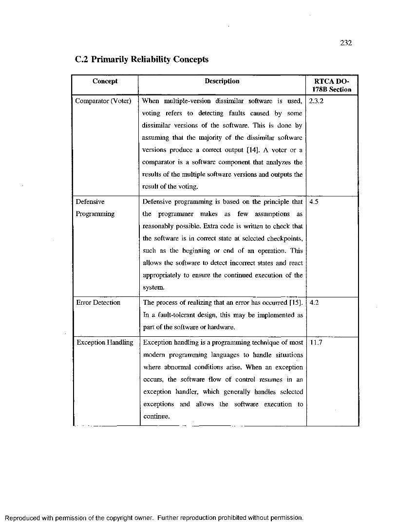
C.2 Primarily Reliability Concepts
232
Concept Description RTCA DO- 1788 Section
Comparator (V oter) When multiple-version dissimilar software is used,
voting refers to detecting faults caused by some
dissimilar versions of the software. This is done by
assuming that the majority of the dissimilar software
versions produce a correct output [14]. A voter or a
comparator is a software component that analyzes the
results of the multiple software versions and outputs the
result of the voting.
2.3.2
Defensive
Programming
Defensive programming is based on the principle that
the programmer makes as few assumptions as
reasonably possible. Extra code is written to check that
the software is in correct state at selected checkpoints,
such as the beginning or end of an operation. This
allows the software to detect incorrect states and react
appropriately to ensure the continued execution of the
system.
4.5
Error Detection The process of realizing that an error has occurred [15].
In a fault-tolerant design, this may be implemented as
part of the software or hardware.
4.2
Exception Handling Exception handling is a programming technique of most
modem programming languages to handle situations
where abnormal conditions arise. When an exception
occurs, the software flow of control resumes in an
exception handler, which generally handles selected
exceptions and allows the software execution to
continue.
11.7
Reproduced with permission of the copyright owner. Further reproduction prohibited without permission.

233
Concept Description RTCA DO- 17811 Section
Failure A failure is the inability of a system or system
component to perform a required function within
specified limits. It may be produced when a fault is
encountered [4],
2.2
Fault A fault is a manifestation of an error in software that, if
it occurs, may cause a failure [4], which is a deviation in
the expected performance of the system [15],
2.1.1
Fault Containment In designing and implementing fault tolerant systems,
fault containment is the process of preventing an error
from propagating within a system. Fault containment is
one of four steps required to reconfigure a system from
a faulty state back to some operational state. The other
three steps are fault detection, fault location, and fault
recovery [15].
2.1.2
Fault Detection The process of realizing that a fault has occurred [15]. In
a fault-tolerant design, this may be implemented as part
of the software or hardware.
2.1.1
11.9
Fault Tolerance The built-in capability of a system or software to
provide continued correct execution in the presence of a
limited number of hardware or software faults [4],
2.1.1
4.4
11.1
Immunity The quality or state of being immune [13], A system or
software is immune to some failure condition if it can
detect it and perform an appropriate safety response that
renders it harmless.
2.1.1
Multiple-Version
Dissimilar Software
A form of fault tolerance design technique where a set
of two or more programs developed separately to satisfy
the same functional requirements are used. Errors
specific to one of the versions are detected by
comparison of the multiple outputs [4],
2.1.1
2.3.2
11.1
11.3
Reproduced with permission of the copyright owner. Further reproduction prohibited without permission.

234
Concept Description RTCA DO- 1786 Section
Software
Redundancy
Redundancy is the use of redundant components, which
is exceeding what is necessary or normal [13]. Software
redundancy implies using multiple-version dissimilar
software.
2.1.1
11.1
Table 10: Safety-related concepts that are classified as “primarily reliability”.
C.3 Primarily Integrity Concepts
Concept Description RTCA DO- 1786 Section
Accuracy Degree of conformity of a measure to a standard or a
true value [13].
11.9
Discontinuity A mathematical discontinuity is the property of not
being continuous. A continuous function has the
property that the absolute value of the numerical
difference between the value at a given point and the
value at any point in a neighbourhood of the given point
can be made as close to zero as desired by choosing the
neighbourhood small enough [13].
6.3.2
Integrity Check The act of testing or verifying the integrity of an object.
Integrity is the quality or state of being complete [13],
accurate, and precise.
11.16
Precision The degree of refinement with which an operation is
performed or a measurement stated [13].
11.9
Software Protector Software that provides protection for user modifications
in user-modifiable software, option-selectable software,
and commercial-off-the-shelf software [4],
2.4
Table 11: Safety-related concepts that are classified as “primarily integrity”.
Reproduced with permission of the copyright owner. Further reproduction prohibited without permission.

C.4 Primarily Performance Concepts
235
Concept Description RTCA DO- 178B Section
Scheduling Strategy A strategy is the art of devising or employing plans or
stratagems toward a goal [13]. The goal of a scheduling
strategy is to determine how various active components
share resources. Examples of scheduling strategies
include round robin, rate monotonic, and earliest
deadline first [6],
11.1
Time-Related Software functionality whose output or behaviour is a
function of time such as filters, integrators, and delays.
6.4.2.1
Table 12: Safety-related concepts that are classified as “primarily performance”.
C.5 Primarily Concurrency Concepts
Concept Description RTCA DO- 178B Section
Active An active component is a component that is capable of
generating stimuli concurrently or pseudo (seemingly)
concurrently without being prompted by an explicit
stimulus instance (i.e., devices that appear capable of
“spontaneous” unprompted behaviour such as hardware,
operating system processes and threads, etc.) [6], In
terms of a software component, package, or object,
activeness implies that a thread is continually executing
within the context of that software component, package,
or object.
12.3.3
Multi-Tasking Software that runs with more than one flow of control,
i.e. concurrent software. Different flows of control may
interact at which point their interactions need to be
managed.
11.7
Reproduced with permission of the copyright owner. Further reproduction prohibited without permission.

236
Concept Description RTCA DO- 178B Section
Passive A passive component is a component that cannot
generate its own behaviour, but only reacts when
prompted by a stimulus [6]. In terms of a software
component, package, or object, passiveness implies that
there is no thread that is continually executing within the
context of that software component, package, or object,
but its code is executed as a result of some other active
software component, package, or object. A passive
element is generally event-driven.
11.7
12.3.3
Shared Resource A resource that is shared across multiple software
modules or flows of control (software threads or
processes). Examples of resources include memory,
CPU cycles, network, and others.
11.1
Table 13: Safety-related concepts that are classified as “primarily concurrency”.
Reproduced with permission of the copyright owner. Further reproduction prohibited without permission.
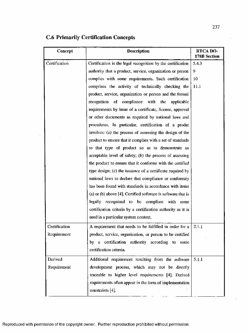
C.6 Primarily Certification Concepts
237
Concept Description RTCA DO- 178B Section
Certification Certification is the legal recognition by the certification
authority that a product, service, organization or person
complies with some requirements. Such certification
comprises the activity of technically checking the
product, service, organization or person and the formal
recognition of compliance with the applicable
requirements by issue of a certificate, license, approval
or other documents as required by national laws and
procedures. In particular, certification of a produt
involves: (a) the process of assessing the design of the
product to ensure that it complies with a set of standards
to that type of product so as to demonstrate an
acceptable level of safety; (b) the process of assessing
the product to ensure that it conforms with the certified
type design; (c) the issuance of a certificate required by
national laws to declare that compliance or conformity
has been found with standards in accordance with items
(a) or (b) above [4]. Certified software is software that is
legally recognized to be compliant with some
certification criteria by a certification authority as it is
used in a particular system context.
5.4.3
9
10
11.1
Certification
Requirement
A requirement that needs to be fulfilled in order for a
product, service, organization, or person to be certified
by a certification authority according to some
certification criteria.
2.1.1
Derived
Requirement
Additional requirement resulting from the software
development process, which may not be directly
traceable to higher level requirements [4], Derived
requirements often appear in the form of implementation
constraints [4],
5.1.1
Reproduced with permission of the copyright owner. Further reproduction prohibited without permission.

238
Concept Description RTCA DO- 178B Section
Deviation Difference in the output or execution of a process, such
as the design or implementation processes, from its plan.
8.2
Hardware / Software The boundary at which software and hardware directly 6.4.3Interface communicate with each other. This is usually done at 11.1
the bit or byte level. 11.9
Traceability The evidence of an association between items, such as 5.3.1
between process outputs, between an output and its
originating process, or between a requirement and its
implementation [4]. Horizontal traceability expresses
relationship between items in different phases of the
development life cycle, such as the relationship between
a design component and software requirements. On the
other hand, vertical traceability expresses relationship
between items in the same phase of the development life
cycle, such as the relationship between two software
requirements.
5.5
Table 14: Safety-related concepts that are classified as “primarily certification”.
C.7 Primarily Design Concepts
Concept Description RTCA DO- 1788 Section
COTS Software Commercially available applications sold by vendors
through public catalogue listings. COTS software is not
intended to be customized or enhanced. Contract-
negotiated software developed for a specific application
is not COTS software [4].
2.4
11.1
Compacted
Expression
A shorter, but equal, form of an expression such as a
mathematical expression.
11.7
Reproduced with permission of the copyright owner. Further reproduction prohibited without permission.

239
Concept Description RTCA DO- 178B Section
Complexity The degree to which a system, software, or component
has a design and implementation that is difficult to
understand and verify [16]. Increasing the complexity
level of software makes it harder to formulate its overall
behaviour, even when given almost complete
information about its atomic components and their inter
relations [17]. It also makes it harder to verify the
software design and the fulfilment of the safety
objectives [4], Examples of complexity measures
include level of nesting, cyclomatic complexity,
conditional structure, unconditional branches, number of
entries into a code component, and number of exits from
a code component.
5.2.2
6.3.4
11.7
Coupling Coupling is a factor of the inter-module complexity of
software [18], which represents the strength of
connection between two modules [19], [20], Myers
identified several types of coupling in [21], namely,
content coupling, common coupling, external coupling,
control coupling, stamp coupling, and data coupling.
11.8
Data Alias In software, a data alias is a name for a software
variable, which is also accessible through another
different name. Essentially, the same data is known and
accessed under different names. Although allowed by
programming languages, this technique is generally
avoided in safety-critical software as they may introduce
confusion.
11.7
Reproduced with permission of the copyright owner. Further reproduction prohibited without permission.
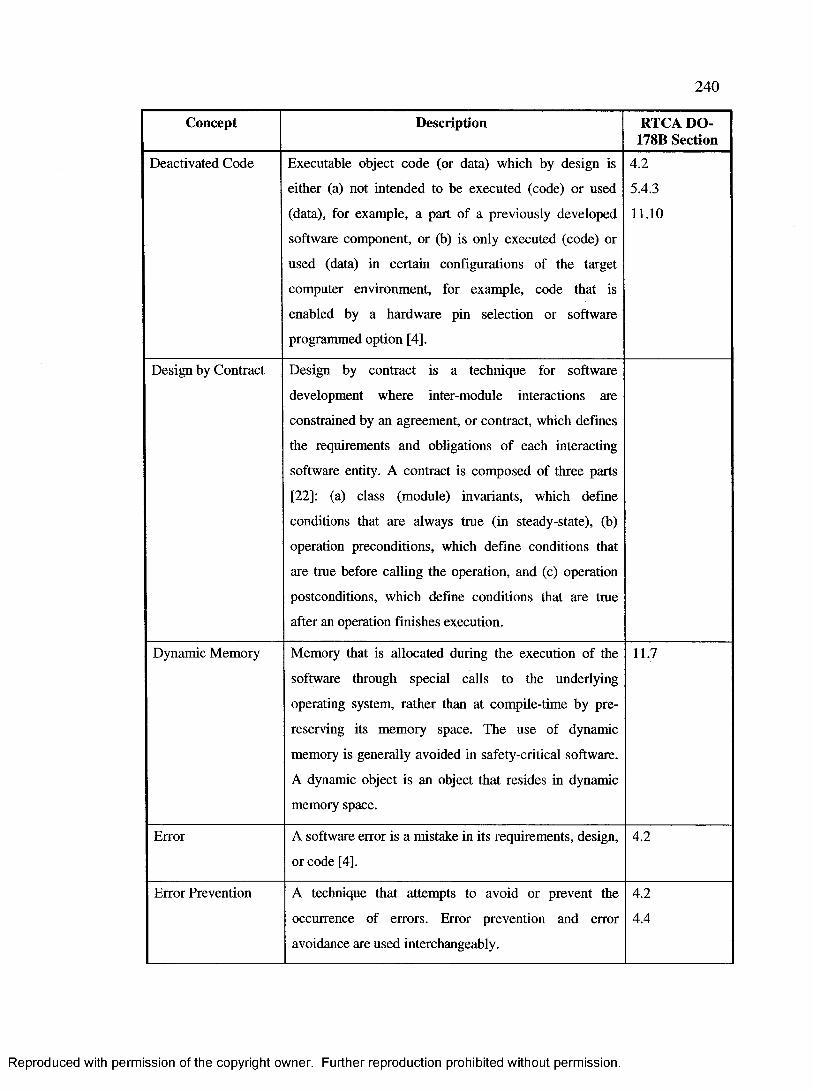
240
Concept Description RTCA DO- 178B Section
Deactivated Code Executable object code (or data) which by design is
either (a) not intended to be executed (code) or used
(data), for example, a part of a previously developed
software component, or (b) is only executed (code) or
used (data) in certain configurations of the target
computer environment, for example, code that is
enabled by a hardware pin selection or software
programmed option [4].
4.2
5.4.3
11.10
Design by Contract Design by contract is a technique for software
development where inter-module interactions are
constrained by an agreement, or contract, which defines
the requirements and obligations of each interacting
software entity. A contract is composed of three parts
[22]: (a) class (module) invariants, which define
conditions that are always true (in steady-state), (b)
operation preconditions, which define conditions that
are tme before calling the operation, and (c) operation
postconditions, which define conditions that are tme
after an operation finishes execution.
Dynamic Memory Memory that is allocated during the execution of the
software through special calls to the underlying
operating system, rather than at compile-time by pre
reserving its memory space. The use of dynamic
memory is generally avoided in safety-critical software.
A dynamic object is an object that resides in dynamic
memory space.
11.7
Error A software error is a mistake in its requirements, design,
or code [4],
4.2
Error Prevention A technique that attempts to avoid or prevent the
occurrence of errors. Error prevention and error
avoidance are used interchangeably.
4.2
4.4
Reproduced with permission of the copyright owner. Further reproduction prohibited without permission.

241
Concept Description RTCA DO- 178B Section
Field-Loadable Field-loadable software refers to software or data tables 2.5
Software that can be loaded without removing the system or 6.4.3
equipment from its installation [4], 11.1
Formal Method A formal method of software development is a process
for developing software that exploits the power of
mathematical notation and mathematical proofs [23]. It
involves the use of formal logic, discrete mathematics,
and computer readable languages to improve the
specification and verification of software [4],
12.3.1
Loader A hardware or software that is used to load field-
loadable software.
2.5
Partitioning Software partitioning is a technique for providing 2.1.1
isolation between functionally independent software 2.3.1
components to contain and/or isolate faults and 5.2.2
potentially reduce the effort of the software verification 6.3.3
process. It prevents specific interactions and cross 11.3
coupling interference [4], 11.9
11.10
Previously Software that was developed in a previous project. It 11.1
Developed Software may or may not have been previously certified for use in 11.3
one or more systems. 12.1
Recursion Recursion is a software implementation approach to 6.3.3
solve a problem by breaking it into a smaller problem
that is easier to solve. Recursion is generally avoided in
airborne and safety-critical software due to their high
demand of resources.
11.7
Reproduced with permission of the copyright owner. Further reproduction prohibited without permission.

242
Concept Description RTCA DO- 178B Section
Simulator A device that enables the operator to reproduce or
represent under test conditions phenomena likely to
occur in actual performance [13]. A simulator may be an
actual device, computer program, or a system, which
interfaces to other software or hardware system in the
same manner as the actual devices, which will be
eventually used in the final system. Simulators are often
used when testing software.
12.3.3.5
Software Patch A modification to an object program, in which one or
more of the planned steps of re-compiling, re
assembling or re-linking is bypassed. This does not
include identifiers embedded in the software product,
for example, part numbers and checksums [4].
5.4.3
State-Related Related to a state machine or its states or transitions. 6.4.2.1
Table 15: Safety-related concepts that are classified as “primarily design”.
C.8 Primarily Configuration Concepts
Concept Description RTCA DO- 178B Section
Configuration A system can have multiple configurations, not all of
which are intended to be used in every application.
Therefore, a configuration represents a set of enabled
and disabled functionality. This can lead to deactivated
code that cannot be executed or data that is not used [4],
5.4.3
Option-Selectable
Software
Software that contains software-programmed options,
which may be configured by the user to produce
different possible configurations.
2.4
11.1
Reproduced with permission of the copyright owner. Further reproduction prohibited without permission.
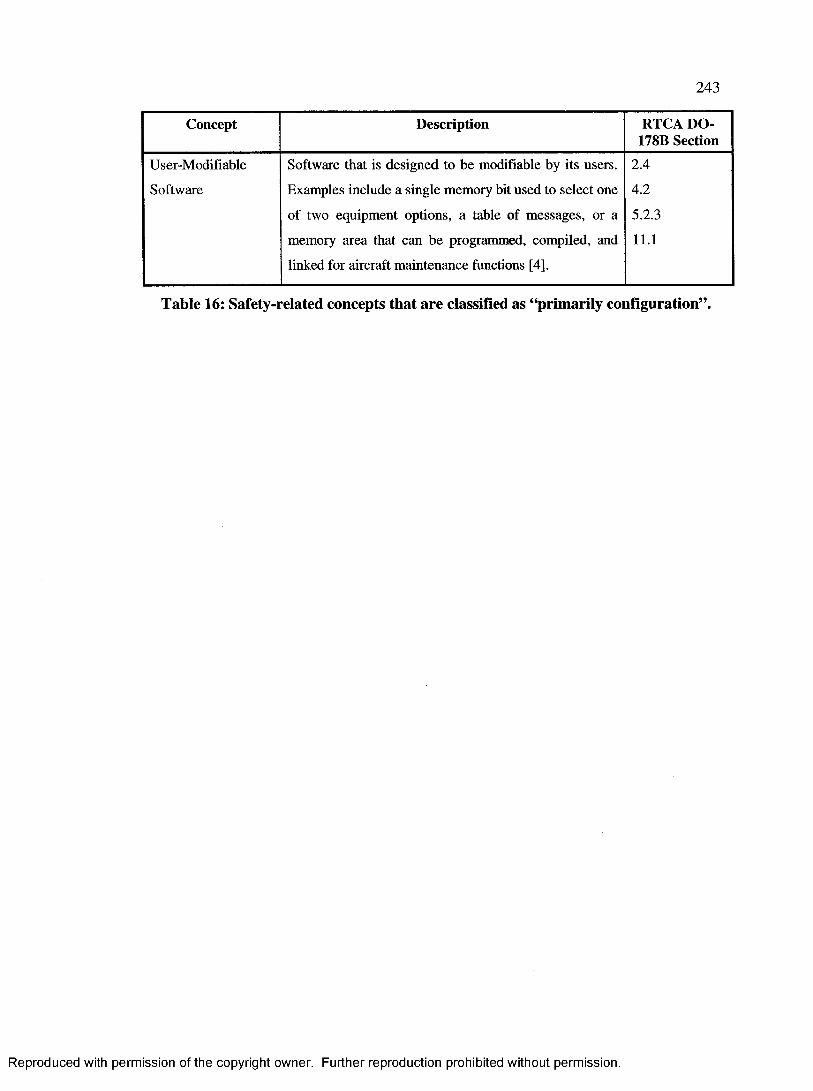
243
Concept Description RTCA DO- 1781} Section
User-Modifiable Software that is designed to be modifiable by its users. 2.4
Software Examples include a single memory bit used to select one 4.2
of two equipment options, a table of messages, or a 5.2.3
memory area that can be programmed, compiled, and
linked for aircraft maintenance functions [4],
11.1
Table 16: Safety-related concepts that are classified as “primarily configuration”.
Reproduced with permission of the copyright owner. Further reproduction prohibited without permission.

244
Appendix D Conceptual Model—Concept Relationships
Source End Relationship Analysis Destination EndRequirement
[0..*]
Is Requirement Of: Each Requirement may be
traceable to zero or more higher-level Requirements.
Conversely, a Requirement may have zero or more
lower-level Requirements (traceable to it).
Requirement
[0..*]
Deviation
[0..*]
References: Each Deviation must deviate from at
least one, potentially more, Requirement. Moreover,
there may exist more than one Deviation from a
particular Requirement. However, not every
Requirement may have Deviations from it, which
would be the case when the design fully conforms to
the Requirements.
Requirement
[1..*]
ImplementationStyle Is Child Class Of: Each ImplementationStyle is a
Style.
Style
ImplementationStyle
[0..*]
References: Each ImplementationStyle may
conform to, or deviate from, zero or more
Requirements. Conversely, a Requirement may
require zero or more ImplementationStyles. In the
case where an ImplementationStyle is not associated
with any Requirements, the ImplementationStyle
signifies a design decision rather than an obligation
or a requirement.
Requirement
[0..*]
BehaviouralStyle Is Child Class Of: Each BehaviouralStyle is a Style. Style
Reproduced with permission of the copyright owner. Further reproduction prohibited without permission.

245
Source End Relationship Analysis Destination End
B ehaviouralStyle
[0-.*]
References: Each BehaviouralStyle may conform to,
or deviate from, zero or more Requirements.
Conversely, a Requirement may require zero or more
BehaviouralStyles. In the case where a
BehaviouralStyle is not associated with any
Requirements, the BehaviouralStyle signifies a
design decision rather than an obligation or a
requirement.
Requirement
[0..*]
Nature
[0..*]
References: A Nature may have been used solely as
a design decision, in which case it is not associated
with any Requirements, or it may have been used to
conform to one or more Requirements. Conversely, a
Requirement may exist but not cause any Natures, or
it may cause one or more Natures.
Requirement
[0..*]
Rationale
[0..*]
References: Each Rationale must be associated with
at least one, potentially more, Requirement.
Moreover, there may exist more than one Rationale
associated with a particular Requirement. However,
not every Requirement may have Rationales
associated with it. However, such a case is
uncommon because it would mean that there are no
design elements traceable to this Requirement.
Requirement
[1..*]
Reaction Is Child Class Of: Each Reaction is an Event. Event
Reaction
[0..*]
Is Consequence Of: Each Reaction is a consequence
of one or more Events because it is executed in
response to the Events. However, each Event may
not cause any reactions at all, or it may cause one or
several Reactions. Since Reactions are Events by
inheritance, then a terminal Reaction, which is the
last Reaction in a chain of Reactions, does not cause
any more Reactions.
Event
[1.*]
Reproduced with permission of the copyright owner. Further reproduction prohibited without permission.

246
Source End Relationship Analysis Destination End
SafetyCritical
[1..*]
Triggers: A SafetyCritical entity may trigger zero or
or more Events. A particular Event may not be
triggered by any SafetyCritical entity, or it may be
triggered by one or more SafetyCritical entities.
Event
[0..*]
Partition
[0..*]
References: A Partition may exist to fulfill one or
more Requirements, or it may exist as a design
decision to isolate functionally independent elements
such that a failure in one component does not cause
the other to fail. Conversely, a Requirement may or
may not require one or more Partitions to be
performed.
Requirement
[0..*]
Partition
[0..*]
Is Partitioned From: By definition, a Partition is
always Partitioned from one or more SafetyCritical
entities. However, a SafetyCritical entity may not
necessarily have one or more Partitions from it.
SafetyCritical
[1..*]
Handler
[0..*]
Handles: A Handler handles at least one Event, and
it usually handles more than one Event. However,
one or more Events may not necessarily be handled
by a Handler. The latter case may occur for Events
that are not of interest in the system, such as non
safety-critical events. In addition, it usually occurs
for many Reactions, which are Events by
inheritance.
Event
[1.*]
Handler
[0.*]
Performs: A Handler performs one or more
Reactions. However, a Reaction may not necessarily
be performed by a Handler, or it may be performed
by one or more Handlers.
Reaction
[1..*]
Reproduced with permission of the copyright owner. Further reproduction prohibited without permission.

247
Source End Relationship Analysis Destination EndMonitor
[0..*]
Monitors: A Monitor monitors one or more
SafetyCritical entities. However, not every
SafetyCritical entity is monitored by a monitor. It is
also possible for a SafetyCritical entity to be
monitored by more than one Monitor.
SafetyCritical
[1..*]
Monitor
[0..*]
Detects: A Monitor detects at least, but usually more
than, one Event. However, an Event may go
undetected by Monitors, or it may be detected by one
or more Monitors.
Event
[1.*]
Monitor
[1..*]
Notifies: Each Handler is notified by at least one
Monitor. However, some Monitors may not
necessarily notify any Handlers, and a Monitor may
notify more than one Handler.
Handler
[0..*]
Simulator
[0..*]
Simulates: A Simulator simulates at least one
SafetyCritical entity. A SafetyCritical entity may not
have any Simulators, or it may have one or more
Simulators. For example, a radar may have two
simulators, with each one simulating the radar’s
behaviour under different environmental conditions.
Another example is having two different versions for
a particular Simulator.
SafetyCritical
[1.*]
Strategy
[0..1]
Describes Design Of: A Strategy describes the
design of one or more SafetyCritical entities. In
addition, a SafetyCritical entity’s design may, or
may not, be described by a Strategy.
SafetyCritical
[1..*]
Formalism
[0-1]
Describes Formalism Of: A Formalism describes
the formalism of one or more SafetyCritical entities.
In addition, a SafetyCritical entity’s formalism may,
or may not, be described by a Formalism.
SafetyCritical
[1..*]
Reproduced with permission of the copyright owner. Further reproduction prohibited without permission.
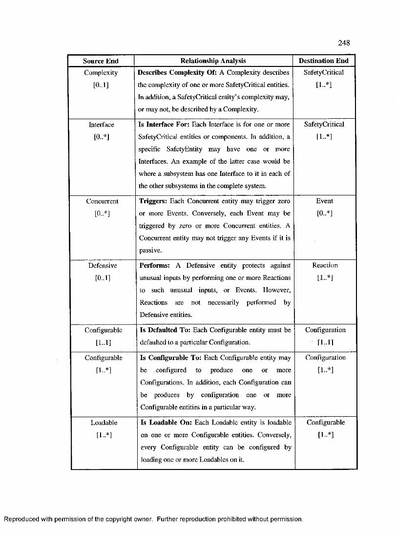
248
Source End Relationship Analysis Destination EndComplexity
[0..1]
Describes Complexity Of: A Complexity describes
the complexity of one or more SafetyCritical entities.
In addition, a SafetyCritical entity’s complexity may,
or may not, be described by a Complexity.
SafetyCritical
[1.*]
Interface
[0..*]
Is Interface For: Each Interface is for one or more
SafetyCritical entities or components. In addition, a
specific SafetyEntity may have one or more
Interfaces. An example of the latter case would be
where a subsystem has one Interface to it in each of
the other subsystems in the complete system.
SafetyCritical
[I..*]
Concurrent
[0..*]
Triggers: Each Concurrent entity may trigger zero
or more Events. Conversely, each Event may be
triggered by zero or more Concurrent entities. A
Concurrent entity may not trigger any Events if it is
passive.
Event
[0..*]
Defensive
[0..1]
Performs: A Defensive entity protects against
unusual inputs by performing one or more Reactions
to such unusual inputs, or Events. However,
Reactions are not necessarily performed by
Defensive entities.
Reaction
[1.*]
Configurable
[1-1]
Is Defaulted To: Each Configurable entity must be
defaulted to a particular Configuration.
Configuration
[1-1]
Configurable
[1..*]
Is Configurable To: Each Configurable entity may
be configured to produce one or more
Configurations. In addition, each Configuration can
be produces by configuration one or more
Configurable entities in a particular way.
Configuration
[1..*]
Loadable
[1..*]
Is Loadable On: Each Loadable entity is loadable
on one or more Configurable entities. Conversely,
every Configurable entity can be configured by
loading one or more Loadables on it.
Configurable
[1..*]
Reproduced with permission of the copyright owner. Further reproduction prohibited without permission.

249
Source End Relationship Analysis Destination EndLoadable
[0. *3
Requires: Loading a Loadble entity may require
specific base Configurations for it to be Loaded. For
example, loading a particular software patch may
require pre-loading earlier patches. However, there
may not be such a requirement if the patch is a
complete and comprehensive patch, rather than an
incremental patch. Conversely, not every
Configuration is required by Loadable entities.
Configuration
[0.*]
Loadable
[1..*]
Produces: A Configuration may be produced by
loading a Loadable. A Loadable may produce more
than Configuration if loaded on different base
Configurations. For a Configuration to be produced,
at least one Loadable must be loaded.
Configuration
[1..*]
Configurator
[1.*]
Configures: A Configurator configures one or more
Configurable entities. A Configurable entity may be
configured by more than one Configurator, such as
the case where the Configurators configure different
aspects of the Configurable entity.
Configurable
[1.*]
Configurator
[I-*]
Loads: A Configurator loads one or more Loadables.
In addition, a Loadable is loaded by one or more
Configurators.
Loadable
[1.*]
Comparator
[1-1]
Compares: A Comparator compares the outputs of
at least two Replicated entities. The output of a
Replicated entity is compared by exactly one
Comparator.
Replicated
[2..*]
ReplicationGroup
[1-13
Owns: Each ReplicationGroup has exactly one
Comparator.
Comparator
[1-1]
ReplicationGroup
[1-13
Owns: Each ReplicationGroup has at least two
Replicated entities.
Replicated
[2..*]
Table 17: Analysis of conceptual model concept relationships.
Reproduced with permission of the copyright owner. Further reproduction prohibited without permission.

250
Appendix E Gomaa’s Class Classification
This section identifies Gomaa’s class classifications as described in [7]. Each
classification is represented by a unique stereotype. The stereotypes are shown in Figure
16.
« t i m e r »
« i n t e r f a c e » « e n t i t y »
« s y s t e min te r f a c e »
« u s e rin te r f a c e »
« a l g o r i t h m »
« c o n t r o l »
« d e v ic ein te r ta c e »
« c o o r d i n a t o r »
« a p p lic a tio nl o g i c »
« a p p l i c a t i o n »
« b u s i n e s sl o g i c »
« s t a t ed e p en d e n tc o n t r o l»
« in p u t/o u tp u tdev ice
in te r f a c e »
« in p u tdev ice
in te r f a c e »
« o u tp u tdev ice
in te r f a c e »
Figure 16: Gomaa’s classification of application classes using stereotypes [7].
Reproduced with permission of the copyright owner. Further reproduction prohibited without permission.
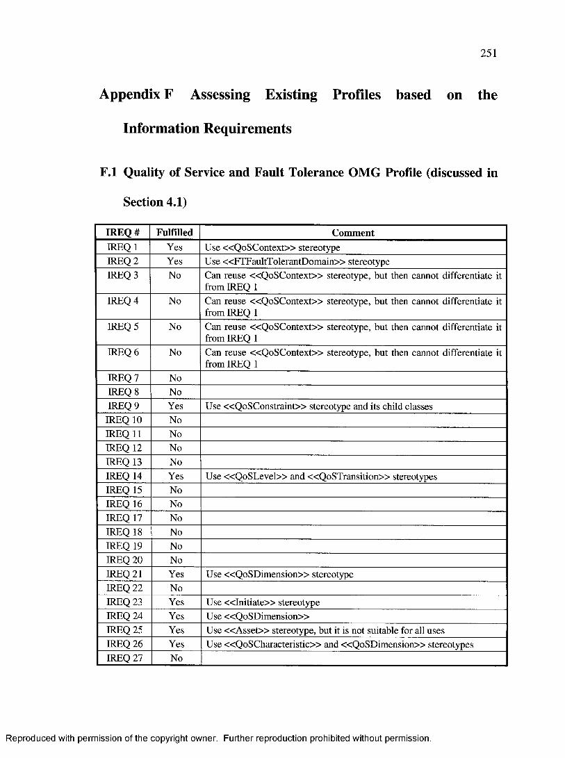
251
Appendix F Assessing Existing Profiles based on the
Information Requirements
F.l Quality of Service and Fault Tolerance OMG Profile (discussed in
Section 4.1)
IREQ# Fulfilled CommentIREQ 1 Yes Use «Q oSC ontext» stereotypeIREQ 2 Yes Use «FTFaultTolerantDomain» stereotypeIREQ 3 No Can reuse «Q oSC ontext» stereotype, but then cannot differentiate it
from IREQ 1IREQ 4 No Can reuse «Q oSC ontext» stereotype, but then cannot differentiate it
from IREQ 1IREQ 5 No Can reuse «Q oSC ontext» stereotype, but then cannot differentiate it
from IREQ 1IREQ 6 No Can reuse «Q oSC ontext» stereotype, but then cannot differentiate it
from IREQ 1IREQ 7 NoIREQ 8 NoIREQ 9 Yes Use «QoSConstraint» stereotype and its child classesIREQ 10 NoIREQ 11 NoIREQ 12 NoIREQ 13 NoIREQ 14 Yes Use «Q oS L evel» and «Q oSTransition» stereotypesIREQ 15 NoIREQ 16 NoIREQ 17 NoIREQ 18 NoIREQ 19 NoIREQ 20 NoIREQ 21 Yes Use «QoSDim ension» stereotypeIREQ 22 NoIREQ 23 Yes Use « In it ia te » stereotypeIREQ 24 Yes Use «QoSDim ension»IREQ 25 Yes Use « A s s e t» stereotype, but it is not suitable for all usesIREQ 26 Yes Use «QoSCharacteristic» and «QoSDimension» stereotypesIREQ 27 No
Reproduced with permission of the copyright owner. Further reproduction prohibited without permission.

252
IREQ# Fulfilled CommentIREQ 28 NoIREQ 29 Yes Use «FTReplicationStyle» and «FTFaultTolerantDomain»
stereotypesIREQ 30 NoIREQ 31 Yes Use «FTReplicationStyle» and «FTFaultTolerantDomain»
stereotypesIREQ 32 NoIREQ 33 NoIREQ 34 Yes The simulation parameters may be specified by using the
«Q oS V alue» stereotype and its child classesIREQ 35 NoIREQ 36 NoIREQ 37 NoIREQ 38 Yes Can use «Q oSV alue» stereotype, but it may get confusing with others
such as IREQ 40IREQ 39 NoIREQ 40 Yes Use « Q oS V alue» stereotype and its child classesIREQ 41 NoIREQ 42 NoIREQ 43 NoIREQ 44 NoIREQ 45 NoIREQ 46 NoIREQ 47 NoIREQ 48 NoIREQ 49 NoIREQ 50 NoIREQ 51 NoIREQ 52 Yes Use Fault-Tolerance sub-profileIREQ 53 Yes Use Fault-Tolerance sub-profile, and specifically the
«FTReplicationStyle» stereotypeIREQ 54 Yes Use Fault-Tolerance sub-profile, and specifically the
«FTReplicationStyle» and «FTFaultTolerantDomain» stereotypesTotal 17 Only 17 information requirements out of 54 are fulfilled
Table 18: Assessing the Quality of Service and Fault Tolerance OMG profile based
on the information requirements.
Reproduced with permission of the copyright owner. Further reproduction prohibited without permission.

253
F.2 Schedulability, Performance, and Time OMG Profile (discussed in
Section 4.2)
IREQ# Fulfilled CommentIREQ 1 NoIREQ 2 NoIREQ 3 NoIREQ 4 Yes Use «PA contex t» stereotypeIREQ 5 Yes Use «SA situation» stereotypeIREQ 6 NoIREQ 7 NoIREQ 8 NoIREQ 9 No
IREQ 10 NoIREQ 11 NoIREQ 12 NoIREQ 13 NoIREQ 14 NoIREQ 15 NoIREQ 16 NoIREQ 17 NoIREQ 18 NoIREQ 19 NoIREQ 20 Yes Use « S A trigger» stereotypeIREQ 21 NoIREQ 22 Yes Use «SA response» stereotypeIREQ 23 NoIREQ 24 NoIREQ 25 NoIREQ 26 NoIREQ 27 NoIREQ 28 NoIREQ 29 NoIREQ 30 NoIREQ 31 NoIREQ 32 NoIREQ 33 NoIREQ 34 NoIREQ 35 NoIREQ 36 No
Reproduced with permission of the copyright owner. Further reproduction prohibited without permission.
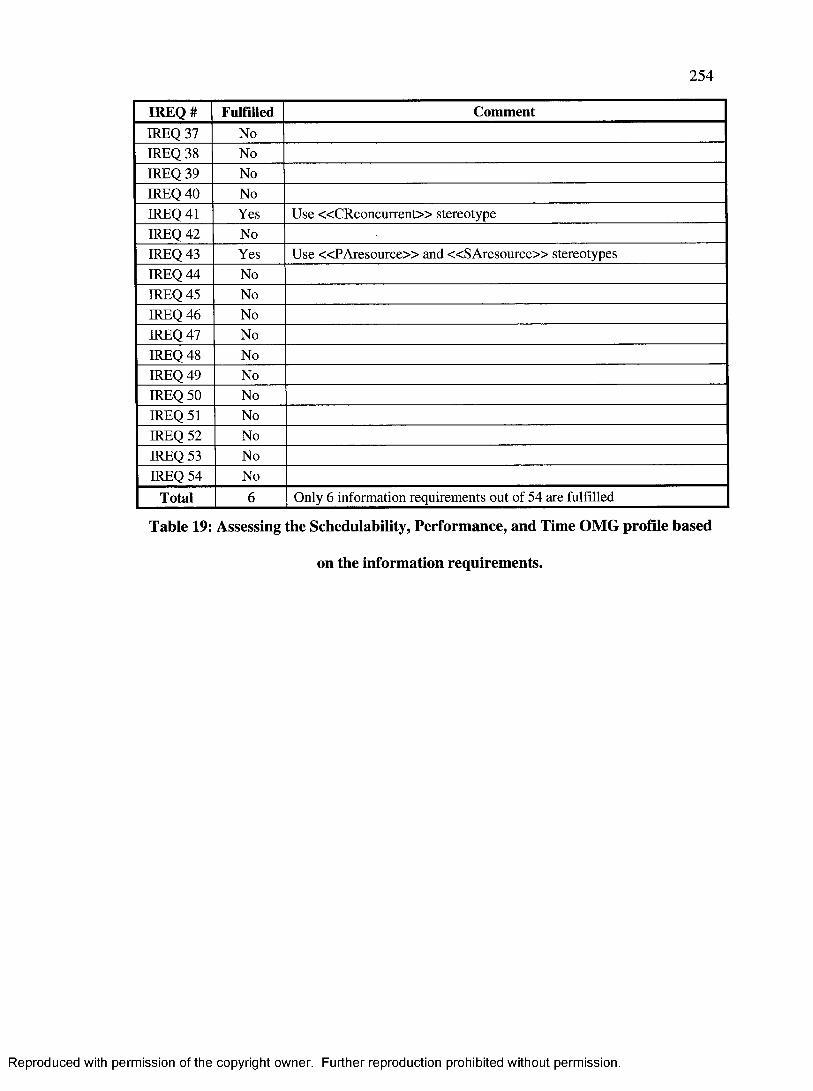
254
IREQ# Fulfilled CommentIREQ 37 NoIREQ 38 NoIREQ 39 NoIREQ 40 NoIREQ 41 Yes Use «CRconcurrent» stereotypeIREQ 42 NoIREQ 43 Yes Use «PA resource» and «SA resource» stereotypesIREQ 44 NoIREQ 45 NoIREQ 46 NoIREQ 47 NoIREQ 48 NoIREQ 49 NoIREQ 50 NoIREQ 51 NoIREQ 52 NoIREQ 53 NoIREQ 54 No
Total 6 Only 6 information requirements out of 54 are fulfilled
Table 19: Assessing the Schedulability, Performance, and Time OMG profile based
on the information requirements.
Reproduced with permission of the copyright owner. Further reproduction prohibited without permission.

255
F.3 HIDOORS Profile (discussed in Section 4.3)
IREQ# Fulfilled CommentIREQ 1 NoIREQ 2 NoIREQ 3 NoIREQ 4 Yes Reuse «P A con tex t» stereotype from SPT profileIREQ 5 Yes Reuse « SAsituation» stereotype from SPT profileIREQ 6 NoIREQ 7 NoIREQ 8 NoIREQ 9 NoIREQ 10 NoIREQ 11 NoIREQ 12 NoIREQ 13 NoIREQ 14 NoIREQ 15 NoIREQ 16 NoIREQ 17 NoIREQ 18 NoIREQ 19 NoIREQ 20 Yes Use the « H IE v en t» stereotype, or reuse «S A trigger» stereotype
from SPT profileIREQ 21 NoIREQ 22 Yes Reuse « SAresponse» stereotype from SPT profileIREQ 23 NoIREQ 24 NoIREQ 25 NoIREQ 26 NoIREQ 27 NoIREQ 28 NoIREQ 29 NoIREQ 30 NoIREQ 31 NoIREQ 32 NoIREQ 33 NoIREQ 34 NoIREQ 35 NoIREQ 36 NoIREQ 37 NoIREQ 38 No
Reproduced with permission of the copyright owner. Further reproduction prohibited without permission.

256
IREQ# Fulfilled CommentIREQ 39 NoIREQ 40 NoIREQ 41 Yes Use the «H IConcurrent» stereotype, or reuse «CRconcurrent»
stereotype from SPT profileIREQ 42 NoIREQ 43 Yes Reuse «PA resource» and «SA resource» stereotypes from SPT
profileIREQ 44 NoIREQ 45 NoIREQ 46 NoIREQ 47 NoIREQ 48 NoIREQ 49 NoIREQ 50 NoIREQ 51 NoIREQ 52 NoIREQ 53 NoIREQ 54 No
Total 6 Only 6 information requirements out of 54 are fulfilled
Table 20: Assessing the HIDOORS profile based on the information requirements.
Reproduced with permission of the copyright owner. Further reproduction prohibited without permission.

257
F.4 Effects of Message Loss, Delay, and Corruption (discussed in
Section 4.4)
IREQ# Fulfilled CommentIREQ 1 Yes Use « sa fe behaviour», « sa fe dependency», and « sa fe lin k s»
stereotypesIREQ 2 NoIREQ 3 NoIREQ 4 NoIREQ 5 NoIREQ 6 NoIREQ 7 NoIREQ 8 NoIREQ 9 Yes Use « guaran tee» stereotypeIREQ 10 NoIREQ 11 NoIREQ 12 NoIREQ 13 NoIREQ 14 NoIREQ 15 NoIREQ 16 NoIREQ 17 NoIREQ 18 NoIREQ 19 NoIREQ 20 NoIREQ 21 NoIREQ 22 NoIREQ 23 NoIREQ 24 NoIREQ 25 Yes Use « c r itic a l» stereotypeIREQ 26 Yes Use « c r itic a l» stereotype and its “level” tagged valueIREQ 27 NoIREQ 28 Yes Use « erro r handling» stereotypeIREQ 29 Yes Use «containm ent» stereotypeIREQ 30 NoIREQ 31 NoIREQ 32 NoIREQ 33 NoIREQ 34 NoIREQ 35 NoIREQ 36 No
Reproduced with permission of the copyright owner. Further reproduction prohibited without permission.

258
IREQ# Fulfilled CommentIREQ 37 NoIREQ 38 NoIREQ 39 NoIREQ 40 NoIREQ 41 NoIREQ 42 NoIREQ 43 NoIREQ 44 NoIREQ 45 NoIREQ 46 NoIREQ 47 NoIREQ 48 NoIREQ 49 NoIREQ 50 NoIREQ 51 NoIREQ 52 Yes Use «redundancy» stereotypeIREQ 53 NoIREQ 54 No
Total 7 Only 7 information requirements out of 54 are fulfilled
Table 21: Assessing the Effects of Messages profile based on the information
requirements.
Reproduced with permission of the copyright owner. Further reproduction prohibited without permission.

259
F.5 Patterns for Reliability and Safety (discussed in Section 4.5)
IREQ# Fulfilled CommentIREQ 1 NoIREQ 2 NoIREQ 3 NoIREQ 4 NoIREQ 5 NoIREQ 6 NoIREQ 7 NoIREQ 8 NoIREQ 9 NoIREQ 10 NoIREQ 11 NoIREQ 12 NoIREQ 13 NoIREQ 14 NoIREQ 15 NoIREQ 16 NoIREQ 17 NoIREQ 18 NoIREQ 19 NoIREQ 20 NoIREQ 21 NoIREQ 22 NoIREQ 23 NoIREQ 24 NoIREQ 25 NoIREQ 26 Yes Use “qosSafety” constraintIREQ 27 NoIREQ 28 NoIREQ 29 No Paper introduces some patterns to model this, but only for use casesIREQ 30 NoIREQ 31 NoIREQ 32 NoIREQ 33 NoIREQ 34 NoIREQ 35 NoIREQ 36 NoIREQ 37 NoIREQ 38 NoIREQ 39 No
Reproduced with permission of the copyright owner. Further reproduction prohibited without permission.

260
IREQ# Fulfilled CommentIREQ 40 NoIREQ 41 NoIREQ 42 NoIREQ 43 NoIREQ 43 NoIREQ 46 NoIREQ 47 NoIREQ 48 NoIREQ 49 NoIREQ 50 NoIREQ 51 NoIREQ 52 No Paper introduces some patterns to model this, but only for use casesIREQ 53 NoIREQ 54 No
Total 1 Only 1 information requirement out of 54 is fulfilled
Table 22: Assessing patterns for Reliability and Safety based on the information
requirements.
Reproduced with permission of the copyright owner. Further reproduction prohibited without permission.

261
F.6 Assessing Existing Profiles based on the Safety Information
Requirements—Summary (discussed in section 4.6)
IREQ# OMG QoS &
FT
OMGSPT
HIDOORS Effects of Messages
Patterns AllCombined
IREQ 1 Yes Yes YesIREQ 2 Yes YesIREQ 3IREQ 4 Yes Yes YesIREQ 5 Yes Yes YesIREQ 6IREQ 7IREQ 8IREQ 9 Yes Yes YesIREQ 10IREQ 11IREQ 12IREQ 13IREQ 14 Yes YesIREQ 15IREQ 16IREQ 17IREQ 18IREQ 19IREQ 20 Yes Yes YesIREQ 21 Yes YesIREQ 22 Yes Yes YesIREQ 23 Yes YesIREQ 24 Yes YesIREQ 25 Yes Yes YesIREQ 26 Yes Yes Yes YesIREQ 27IREQ 28 Yes YesIREQ 29 Yes Yes YesIREQ 30IREQ 31 Yes YesIREQ 32IREQ 33IREQ 34 Yes YesIREQ 35
Reproduced with permission of the copyright owner. Further reproduction prohibited without permission.

262
IREQ# OMG QoS &
FT
OMGSPT
HIDOORS Effects of Messages
Patterns AllCombined
IREQ 36IREQ 37IREQ 38 Yes YesIREQ 39IREQ 40 Yes YesIREQ 41 Yes Yes YesIREQ 42IREQ 43 Yes Yes YesIREQ 44IREQ 45IREQ 46IREQ 47IREQ 48IREQ 49IREQ 50IREQ 51IREQ 52 Yes Yes YesIREQ 53 Yes - YesIREQ 54 Yes Yes
Total (Max = 54)
17 6 6 7 1 24
Percentage(%)
31% 11% 11% 13% 2% 44%
Table 23: Assessment summary of existing UML profiles based on the information
requirements.
Reproduced with permission of the copyright owner. Further reproduction prohibited without permission.

263
Appendix G Additional UML Profile Examples
G.l COTS Software
The example in Figure 17 shows an aircraft navigation controller, which controls the
flight of the aircraft including all auto pilot programmes.
NavigationControiler controls the aircraft’s flight paths. Therefore, it is a safety-
critical element. This is marked explicitly on the diagram by stereotyping
NavigationContr oiler with a « S a fe ty C ritic a l» (5.2.17) stereotype. Because the
failure of this system can result in conditions difficult to handle by the aircraft’s crew,
this class has been assigned software level C. This is indicated by the “CriticalityLevel”
tagged value of the « S a fe ty C ritic a l» (5.2.17) stereotype.
NavigationContr oiler needs to know the allowed flight paths of the aircraft. In this
example, safeFiightPaths serves as the database that contains all the navigation
information relevant to the currently needed flight paths. It is safety-critical because a
safety-critical class, namely NavigationControiier, depends on it. This is marked
explicitly on the diagram by stereotyping it with a « S a fe ty C ritic a l» (5.2.17) stereotype
and assigning it a software level equal to at least that of the class that depends on it as
indicated by the “CriticalityLevel” tagged. The developers of this navigation controller
system decided to purchase COTS software and use it to store the flight paths. This is
indicated in the diagram by stereotyping SafeFiightPaths with « N a t u r e » (5.2.13)
and setting the “Kind” tagged value to “COTS”.
Reproduced with permission of the copyright owner. Further reproduction prohibited without permission.

264
For the aircraft’s flight paths to be meaningful, maps of the world are needed. They are
necessary for verifying the safe flight paths as well as displaying them to the pilots.
Unlike the flight paths, they are static information that rarely change, and therefore they
are maintained as a separate class outside of SafeFiightPaths. They are maintained in
CurrentiyUsedWoridMaps, which contains the world maps that are needed for the
current flight. It is safety-critical because a safety-critical class, namely
SafeFiightPaths, depends on it. This is marked explicitly on the diagram by
stereotyping it with a « S a fe ty C ritic a l» (5.2.17) stereotype and assigning it a software
level equal to at least that of the class that depends on it as indicated by the
“CriticalityLevel” tagged.
This diagram shows safety-critical model elements. Hence, it is stereotyped with
« S a fe ty C o n tex t» (5.2.1). In addition, COTS software is a crucial element of the
software’s certification aspects in airworthiness. Therefore, they must be declared to the
certification authorities. For this reason, this diagram is stereotyped with
«C ertificationC ontex t» (5.2.6) to indicate that it contains information that is highly
relevant to the certification authorities.
« S a f e ty C o n te x t»« C e r t if ic a tio n C o n te x t»
1 B a se d O n 11 R ea d s 1« S a f e ty C r i t ic a l» {Critical ityLevel=C}
C urrentiyU sedW oridM aps
« e n t i t y »« e n t i t y »
« S a f e ty C r i t ic a l»{C rit i cal i ty Level=C}
« N a t u r e » {Kind=COTS}
S afeF iigh tP a ths
« s t a t e d e p e n d e n t c o n t r o l»
« S a f e ty C r i t ic a l»{CriticalityLevel=C}
N avigationControiier
Figure 17: Aircraft’s navigation controller using COTS software (structure).
Reproduced with permission of the copyright owner. Further reproduction prohibited without permission.

265
G.2 Software Partitioning
Software partitioning is a technique for providing isolation between functionally
independent software components to contain and/or isolate faults and potentially reduce
the effort of the software verification process. It prevents specific interactions and cross
coupling interference [1]. Its key advantages are in separating safety-critical software
elements that have different safety levels, so that the failure of the less critical software
does not result in the failure of the more critical software.
The example in Figure 18 shows another section of a navigation system. This system,
which can be put on auto-pilot, has a steering controller that is highly safety-critical,
steeringControiler controls the steering of the aircraft and its movement. Therefore, it
is highly safety-critical and is assigned software level B. Thus, it is stereotyped
« S a fe ty C ritic a l» (5.2.17) and its “CriticalityLevel” tagged value is set to level B.
Because it is highly safety-critical, it also employs defensive programming methods to
protect against unsafe inputs, whether they are manual input from the pilot through
pilotKeyboardinterface, or from the software’s auto pilot system through
AutoPiiotcontroiler. steeringControiier does not perform any action that requires
the aircraft to fly on an altitude below 100 meters unless the aircraft is in the process of
landing. Therefore, it is stereotyped with « D e fe n s iv e » (5.2.27) and has a
“Defendablelnput” tagged value set to “Altitude < 100 m”. It also does not perform any
action that requires the aircraft to change its flight direction in angles of greater than 90
degrees. Thus, another instance of the “Defendablelnput” tagged value is set to “Angle >
90 deg”. In both cases, steeringControiier reports that an illegal operation has
Reproduced with permission of the copyright owner. Further reproduction prohibited without permission.
266
occurred by exeuting the ReportniegationOperation reaction procedure, as evident
from the “Reaction” tagged value that is set to “ReportfllegalOperation” .
AutoPiiotcontr oiler is also safety-critical, but less critical than
steeringControiier. This is because the failure of AutoPiiotcontr oiler only results
in inconvenience for the pilots rather than significantly compromising the level of safety.
If the auto pilot feature fails, the pilots can always manually control the aircraft through
PilotKeyboardinterf ace or some other mechanical device inputs. Therefore,
AutoPiiotcontr oiler was assigned software level D. Thus, it is stereotyped with
« S a fe ty C ritic a l» (5.2.17) and its “CriticalityLevel” tagged value is set to level D. The
interesting thing to note in this example is that AutoPiiotcontroiier was partitioned
from steeringControiier for this very reason - if the auto pilot feature fails, the
steering controller can still execute correctly and ensure the safe flight of the aircraft.
This is stated in the model by stereotyping AutoPiiotcontroiier with « P a r t i t io n »
(5.2.18) and using its “PartitionedFrom” tagged value, set to “SteeringControiier”, and
“Explanation” tagged value, set to “Lower Criticality Level”, to specify this exact
information.
ConvertibleSteeringlnformation is used by PilotDisplaylnterface to display the
current aircraft steering information. What is special about this class is that it can read the
information from steeringControiier and convert it to appropriate units for the pilots
such as conversion from metric units to imperial units, and vice-versa. Again,
ConvertibleSteeringlnf ormation was partitioned away from SteeringControiier
because it is only relevant for displaying the information to the pilots. If it fails, the
Reproduced with permission of the copyright owner. Further reproduction prohibited without permission.

267
aircraft can still resume safe flight through either manual input through
PilotKeyboardinterf ace or auto pilot through AutoPiiotcontroiier. As a result,
ConvertibleSteeringlnf ormation was stereotyped with « P a r t i t io n » (5.2.18) and its
“PartitionedFrom” and “Explanation” tagged values were used to specify that it was
partitioned from steeringControiier because it was “Not Safety Critical”.
It is clear from this discussion that this example has emphasis on safety. Therefore, the
diagram was stereotyped with « S a fe ty C o n tex t» (5.2.1). It should also be noted that
partitioning information has to be submitted to the certification authorities. Therefore, the
diagram was also stereotyped with «C ertificationC ontex t» (5.2.6). Finally, we also
decided to stereotype it with « D esig n C o n tex t» (5.2.7) because it is the result of design
decisions on how software classes are organized with respect to safety. In fact, the
partitioning concept was identified as a design concept in section C.7
One final note is that the higher the software level is, the more expensive it is to develop
it. A direct positive result of the partitioning in this example is that
AutoPiiotcontroiier and ConvertibleSteeringlnformation do not have to go
through the rigorous development and testing methods required for
SteeringControiier, which is of level B.
Reproduced with permission of the copyright owner. Further reproduction prohibited without permission.
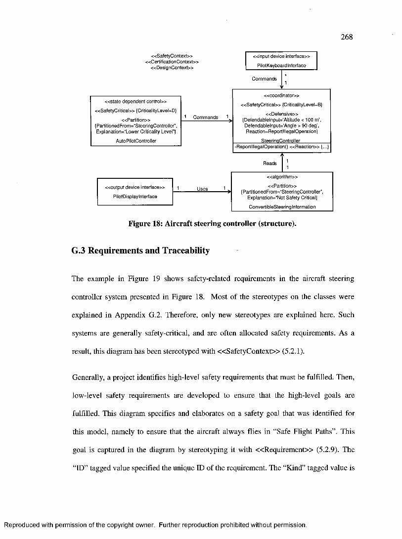
268
« S a f e ty C o n te x t»« C e r t if ic a tio n C o n te x t»
« D e s ig n C o n te x t»
C o m m an d s
1 C o m m an d s 1
R ea d s
U ses
« i n p u t dev ice in te r f a c e »
P ilo tK eyboardln terface
« o u t p u t dev ice in te r f a c e »
PilotD isplaylnterface
« a l g o r i t h m »
« P a r t i t i o n » {PartitionedFrom =,,S teeringC ontro ller”,
Explanation="N ot S afe ty Critical}
C onvertib leS teering Information
« s t a t e d e p en d e n t c o n t r o l»
« S a f e ty C r i t i c a l» {CriticalityLevel=D}
« P a r t i t i o n » {PartitionedFrom ="SteeringC ontroller”, ExplanatiorW 'Low er Criticality Level”}
A utoPiio tcontro iier
« c o o r d in a to r »
« S a f e ty C r i t i c a l» {CriticalityLevel=B}
« D e f e n s i v e » {D efendab lelnpu t=‘Altitude < 100 m’,
D efendab le lnpu t= ‘A ngle > 90 d e g ’, R eaction=R eportlllegalO peration}
____________ SteeringC ontro iier_____________-R eportlllegalO perationO « R e a c t i o n » {...}
Figure 18: Aircraft steering controller (structure).
G.3 Requirements and Traceability
The example in Figure 19 shows safety-related requirements in the aircraft steering
controller system presented in Figure 18. Most of the stereotypes on the classes were
explained in Appendix G.2. Therefore, only new stereotypes are explained here. Such
systems are generally safety-critical, and are often allocated safety requirements. As a
result, this diagram has been stereotyped with « S a fe ty C o n te x t» (5.2.1).
Generally, a project identifies high-level safety requirements that must be fulfilled. Then,
low-level safety requirements are developed to ensure that the high-level goals are
fulfilled. This diagram specifies and elaborates on a safety goal that was identified for
this model, namely to ensure that the aircraft always flies in “Safe Flight Paths”. This
goal is captured in the diagram by stereotyping it with « R eq u ire m e n t» (5.2.9). The
“ID” tagged value specified the unique ID of the requirement. The “Kind” tagged value is
Reproduced with permission of the copyright owner. Further reproduction prohibited without permission.

269
set to “Safety” to identify that this is a safety-related requirement, and its “Specification”
tagged value states what the requirement is, namely ensuring “Safe Flight Paths”.
Because of its high software level, steeringControiier is checked for correctness
using a formal method, namely “Theorem-Proving”. Therefore, it is stereotyped with
« F o rm a lism » (5.2.23) and its “Method” tagged value is set to “Theorem-Proving”. Its
“Kind” tagged value is set to “Full” to indicate that a fully formal method is used.
PilotKeyboardinterf ace serves as an input interface to the pilot. The pilot can use it to
change the flight path of the aircraft. PilotKeyboardinterface has been assigned a
safety requirement to request confirmation from the pilots whenever they wish to change
the flight path. Therefore, it was stereotyped with « R e q u ire m e n t» (5.2.9). Its “ID”
tagged value specifies the unique ID of the requirement, which is “LREQ 1”. Its “Kind”
tagged value was set to “Safety” to indicate that it is a safety requirement. Its
“OfRequirement” tagged value specifies the high-level requirement that this low-level
requirement can be traced to. In this example, it is the “HREQ 1” high-level requirement
that was applied as a stereotype on the diagram. The “Specification” tagged value
specifies that there must be a user confirmation for every path change.
The second safety requirement for “HREQ 1” was assigned to the association between
AutoPiiotcontroiier and steeringControiier. The association was stereotyped with
« R eq u irem en t» (5.2.9) whose “Kind” tagged value is also set to “Safety”. Its “ID”
tagged value specifies the unique ID of the requirement. The “OfRequirement” tagged
value specifies that this requirement is traceable to the “HREQ 1” requirement. The
“Specification” tagged value specifies that the association must ensure that the “Chosen
Reproduced with permission of the copyright owner. Further reproduction prohibited without permission.
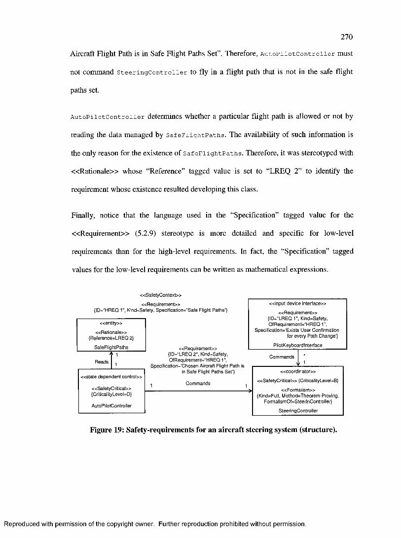
270
Aircraft Flight Path is in Safe Flight Paths Set”. Therefore, AutoPiiotcontroiier must
not command steeringControiier to fly in a flight path that is not in the safe flight
paths set.
AutoPiiotcontroiier determines whether a particular flight path is allowed or not by
reading the data managed by SafeFiightPaths. The availability of such information is
the only reason for the existence of SafeFiightPaths. Therefore, it was stereotyped with
« R a t io n a le » whose “Reference” tagged value is set to “LREQ 2” to identify the
requirement whose existence resulted developing this class.
Finally, notice that the language used in the “Specification” tagged value for the
« R eq u irem en t» (5.2.9) stereotype is more detailed and specific for low-level
requirements than for the high-level requirements. In fact, the “Specification” tagged
values for the low-level requirements can be written as mathematical expressions.
« S a f e ty C o n te x t»
« R e q u i r e m e n t »{ID=“HREQ 1", K ind=Safety, SpecificatiorW 'S afe Flight P a th s ”}
« R e q u i r e m e n t»{ID=“LREQ 2 ”, K ind=Safety, O fR equirem ent=“H REQ 1”,
S pecificatio rW C hosen Aircraft Flight P a th is in S a fe Flight P a th s S e t’}
C o m m an d sR ead s
C om m ands
« e n t i t y »
« R a t i o n a l e » {R eference=LR EQ 2}
S afeF iigh tP aths
« s t a t e d e p e n d e n t c o n t r o l»
« S a f e ty C r i t ic a l» {Critical ityLevel=D}
A utoPiiotcontroiier
« c o o r d i n a t o r »
« S a f e ty C r i t i c a l» {CriticalityLevel=B}
« F o r m a l i s m »{Kind=Full, M ethod=Theorem -Proving,
Form alism O f=SteerinC ontroller}
SteeringC ontro iier
« i n p u t dev ice in te r f a c e »
« R e q u i r e m e n t » {ID=“LREQ 1”, K ind=Safety, O fR equirem ent= ‘‘H REQ 1”,
S p ec ific a tio n ^ E x is ts U ser Confirm ation for every P a th C h an g e ’}
Pilo tK eyboard in terface
Figure 19: Safety-requirements for an aircraft steering system (structure).
Reproduced with permission of the copyright owner. Further reproduction prohibited without permission.

I l l
G.4 Multiple-Version Dissimilar Software
Multiple-version dissimilar software is a common technical solution to reliability
challenges in highly reliable and safety-critical software. The example in Figure 20
shows three dissimilar software versions that function as a radar filter. Those three
dissimilar versions are RadarFilterl, RadarFilter2, and RadarFilter3. Each one of
them is stereotyped with « R e p l ic a te d » to indicate that it is a dissimilar version for
some other class. The “ID” tagged value uniquely identifies the ID of that class within the
replication group that is specified in the “ReplicationGroup” tagged value. In this
example, the replication group is called “RadarFilter”.
Each version of the radar filter logs its output to RadarFiiterResuits.
RadarFilter Re suits compares all three outputs from RadarFilterl, RadarFilter2,
and RadarFiiter3, and determines what the accepted value should be and then it updates
the pilot’s display accordingly. Because of this behaviour, RadarFiiterResuits is
stereotyped with « C o m p a ra to r» (5.2.32) to indicate that it compares outputs from
dissimilar software versions. The “ReplicationGroup” tagged value identifies the
replication group of the multiple version dissimilar software. It is equal to the
“ReplicatedGroup” tagged values of the « R e p lic a te d » (5.2.31) stereotypes for each of
the replicated software versions. The “PolicyParameter” tagged value of the
« C o m p a ra to r» stereotype indicates that RadarFiiterResuits determines the
accepted output based on a majority voting policy. This means that if two of the three
replicated classes agree on a value, their output is accepted as the correct one. The
Reproduced with permission of the copyright owner. Further reproduction prohibited without permission.

272
“ReplicatedEntity” tagged values of the « C o m p a ra to r» (5.2.32) stereotype identify the
classes whose outputs are considered for voting.
Since multiple-version dissimilar software is a reliability-related solution, the diagram
was stereotyped with « R eliab ilityC on tex t» (5.2.2).
Notice that in this case, the classes stereotyped with « R e p lic a te d » (5.2.31) depend
(navigability of association) on the one stereotyped with « C o m p a ra to r» (5.2.32). This
is only because of a design decision in this model where the radar filters are active
components that read the radar input and inform the comparator class accordingly.
However, this will not always be the case. There can be cases where the comparator class
depends on the replicated classes. Therefore, stereotypes « c o m p a ra to r» and
« re p lic a te d » do not suggest any specific association navigability between stereotyped
classes.
« R e l i a b i l i t y C o n te x t»
Log R e s u ltLog R e su lt Log R esu lt
U p d a te D isp lay « o u t p u t d e v ic e i n t e r f a c e »
PilotDisplaylnterface
« a g l o r i t h m »
« R e p l i c a t e d » {ID=“0001 ”, R ep lic a tio n G ro u p = ‘‘R ad a rF ilte r”}
R a d a rF ite r l
« a l g o r i t h m »
« R e p l i c a t e d » {ID=“0 0 0 3 ”, R ep lic a tio n G ro u p = ‘‘R a d a rF ilte r”}
R a d a rF ite r3
« a l g o r i t h m »
« R e p l i c a t e d » {ID=“0 0 0 2 ”, R ep lic a tio n G ro u p = ‘‘R ad a rF ilte r”}
R a d a rF ite r2
« a l g o r i t h m »
« C o m p a r a t o r » { R ep lic a tio n G ro u p = ‘‘R ad a rF ilte r”, P o licy P aram e te r= M ajo rity V o tin g ,
R e p l ic a te d E n ti ty = R a d a rF ilte r1 , R ep lic a te d E n tity = R ad a rF ilte r2 , R ep lica ted E n tity = R ad a rF ilte r3 }
R ad a rF ii te rR e s u its
Figure 20: Multiple-version radar filter system (structure).
Reproduced with permission of the copyright owner. Further reproduction prohibited without permission.

273
G.5 Concurrent Software
This example shows concurrent access to the database presented in Figure 19. As Figure
21 shows, SafeFiightPaths is COTS software as indicated by the « N a t u r e »
stereotype and its “Kind” tagged value. This class is a resource that is subject to
concurrent access from other classes. Therefore, it is stereotyped with « C o n c u r re n t»
(5.2.26) to indicate that it is relevant from a concurrency point of view. Its “Role” tagged
value is set to “Resource” and its “IsShared” “tagged value is set to “true” to indicate that
it is a shared resource.
SafeFiightPaths is subject to concurrent access from
SatelliteCommunicationlnterf ace, Radar Interface, and User Inter face. Each one
of those classes is an active class that may initiate action without explicit invocation from
other software classes in the system. Therefore, each one of them is stereotyped with
« C o n c u r re n t» (5.2.26) whose “Role” tagged value was set to “Active”. Each one of
them has an association to SafeFiightPaths to show that it can read from and write to
it.
« C o n c u rren cyC o n tex t»« P e rfo rm a n c e C o n tex t»
Reads and WritesReads and Writes Reads and Writes
« s y s te m in te rfa c e »
« C o n c u r re n t» {Role=Active}
Radarlnterface
« u s e r in te rfa c e »
« C o n c u r re n t» {Role=Active}
Userlnterface
« s y s te m in te rfa c e »
« C o n c u r re n t» {Role=Active}
SatelliteCommunicationlnterface
« e n t i t y »
« N a t u r e » {Kind=COTS}
« C o n c u r re n t» {Role=Resource, lsShared=true}
________ SafeFiightPaths________
Reproduced with permission of the copyright owner. Further reproduction prohibited without permission.
274
Figure 21: Concurrent access to an aircraft’s COTS software (structure).
Because this diagram involves a concurrency discussion, it is stereotyped with
«C oncurrencyC ontex t» (5.2.5). It is also stereotyped with «P erfo rm anceC ontex t»
(5.2.4) because concurrent access to a shared resource is also relevant from a
performance point of view especially because Radar inter face and
sateiiiteCommunicationinterface are likely to have high-frequency accesses to
SafeFiightPaths.
G.6 Software Monitoring
The example in Figure 22 shows safety-monitoring software. Its purpose is to detect
when the aircraft’s engine temperature becomes too high, and then to react by lowering
the temperature to an acceptable level.
Engine inter face serves as an interface for the aircraft’s engine. Hence, it is stereotyped
with « In te r f a c e » (5.2.25) and its “InterfaceFor” tagged value is set to
“AircraftEngine”. Because the aircraft’s engine is a hardware component, its
“IsBetweenHardwareAndSoftware” tagged value is set to “true”.
Engine inter face is monitored by EngineMonitor, which is stereotyped with
« M o n i to r » (5.2.20). Its “Kind” tagged value is set to “Safety” to indicate that the
purpose of the monitor is to increase the safety level of the system. The
“MonitoredEntity” tagged value is set to “Enginelnterface” to indicate that the class
being monitored is Enginelnterface. The “DetectableEvent” tagged value specifies the
event that can be detected by EngineMonitor, which is EngineTooHot. The
Reproduced with permission of the copyright owner. Further reproduction prohibited without permission.

275
“EventHandler” tagged value is set to “AircraftEngineController” to indicate that
AircraftEngineControiler will be notified when this event occurs.
EngineTooHot represents the event that the engine’s temperature has risen to an
unacceptable level. Thus, it is stereotyped with « E v e n t » (5.2.15) and its
“EffectOnSafetyDirection” tagged value is set to “Negative” to indicate that the
occurrence of this event can have unsafe consequences.
NormalizeEngineTemperature contains the reaction code that will be executed when
the EngineTooHot event occurs. Therefore, it is stereotyped with « R e a c t io n » (5.2.16)
and its “ConsequenceOf ’ tagged value is set to “EngineTooHot”, which is the class name
of the event that triggers the reaction. The “EffectOnSafetyDirection” is set to “Positive”
to indicate that the reaction is intended to increase the safety level.
AircraftEngineController is a safety-critical class because it determines how to
control the aircraft’s engine. Thus, it is stereotyped with « S a fe ty C ritic a l» (5.2.17).
Moreover, it serves as an event handler by recognizing the EngineTooHot event and
executing the NormaiizeEngineTemperature reaction code. Therefore, it is also
stereotyped with « H a n d le r » (5.2.19) stereotype whose “HandleableEvent” tagged
value is set to the “EngineTooHot” event, and its “PerformedReaction” tagged value is
set to the “NormaiizeEngineTemperature” reaction.
Because this diagram discusses safety aspects of the system, it is stereotyped with
« S a fe ty C o n te x t» (5.2.1). Furthermore, it is stereotyped with « S t r a te g y » (5.2.22)
and its “Kind” tagged value is set to “Safety” to indicate that it is a technical solution to
increase the safety level.
Reproduced with permission of the copyright owner. Further reproduction prohibited without permission.
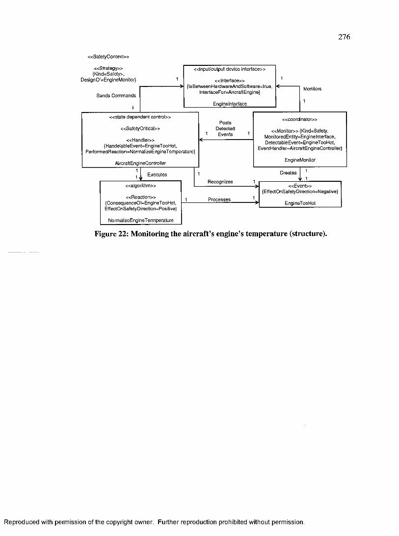
276
« S a f e ty C o n te x t»
« S t r a t e g y »{Kind=Safety>,
D esignOf=EngineM onitor}
M onitorsS e n d s C om m ands
P o s tsD etec ted
E vents
C re a te sE xecu tesvR ec o g n ize s
P ro c e s s e s
« E v e n t »{EffectO nSafetyD irection=N egative}
EngineT ooH ot« R e a c t i o n »
{C onsequenceO f=E ngineT ooH ot,EffectOnSafetyDirection=Positive}
N orm alizeE ngineT erm peratu re
« a l g o r i t h m »
« l n t e r f a c e »{Is B etw een H ard w are A ndS oftw are= true ,
lnterfaceFor=A ircraftEngine}
« in p u t /o u tp u t dev ice in te r f a c e »
E ng ineln te rface
« M o n i t o r » {Kind=Safety, M onitoredEntity=Enginelnterface, D etectableE vent=E ngineT ooH ot,
EventH andler=A ircraftEngineController}
« c o o r d i n a t o r »
EngineM onitor
« H a n d l e r »{H andelableE vent=E ngineT ooH ot,
Perfo rm edR eaction= N orm alizeE ngineT em peratu re}
« s t a t e d e p e n d e n t c o n t r o l»
A ircraftEngineController
« S a f e ty C r i t i c a l»
Figure 22: Monitoring the aircraft’s engine’s temperature (structure).
Reproduced with permission of the copyright owner. Further reproduction prohibited without permission.