a tone mapping algoritm with detail enhancement based on retinex
TRANSCRIPT
A TONE MAPPING ALGORITM WITH DETAIL ENHANCEMENT BASED
ON RETINEX THEORY
1 Po-Cheng Lee(李柏成),
2 Chiou-Shann Fuh (傅楸善)
1 Dept. of Computer Science and Information Engineering,
National Taiwan University, Taipei, Taiwan
E-mail: [email protected] 2 Dept. of Computer Science and Information Engineering,
National Taiwan University, Taipei, Taiwan
E-mail: [email protected]
ABSTRACT
Because of the progress of the digital camera
technique recently, we can directly obtain the HDRI
(High Dynamic Range Image) from camera.
Nevertheless, limited by display, we still transfer the
HDRI to the display which can show LDRI (Low
Dynamic Range Image). This technique is known as
tone-mapping.
The goal of tone-mapping is to compress the
luminance dynamic range into low dynamic range while
decreasing distortion and preserving detail. We use
logarithm first to compress high dynamic range based
on background luminance. The retinex local contrast
enhancement is thus being performed to enhancement
the image in dark regions. Using our method can
preserve most of detail without contrast distortion
especially dark areas.
Keywords tone mapping, tone reproduction, high
dynamic range image;
1. INTRODUCTION The dynamic range is a ratio between the maximum
and minimum physical measures. In photography, we
use "dynamic range" for the luminance range of a scene
being photographed, or the limits of luminance range
that a given digital camera or film can capture, or the
reflectance range of images on photographic papers.
High Dynamic Range Imaging (HDRI or just HDR)
is a set of techniques that allow a greater dynamic range
between the lightest and darkest areas of an image than
current standard digital imaging techniques or
photographic methods. This wide dynamic range allows
HDR images to represent more accurately the range of
intensity levels found in real scenes.
In this paper, we focus on how to compress the HDR
images into the stored image that it can be shown on the
common display. This technique is “tone-mapping”.
The algorithm for resolving tone-mapping can be
classified by two categories: spatial uniform and spatial
varying algorithms.
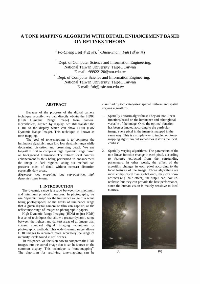
1. Spatially uniform algorithms: They are non-linear
functions based on the luminance and other global
variable of the image. Once the optimal function
has been estimated according to the particular
image, every pixel in the image is mapped in the
same way. This is a simple way to implement tone-
mapping algorithm but sometimes distorts the local
contrast.
2. Spatially varying algorithms: The parameters of the
non-linear function change in each pixel, according
to features extracted from the surrounding
parameters. In other words, the effect of the
algorithm changes in each pixel according to the
local features of the image. Those algorithms are
more complicated than global ones, they can show
artifacts (e.g. halo effect), the output can look un-
realistic, but they can provide the best performance,
since the human vision is mainly sensitive to local
contrast.
(a) (b)
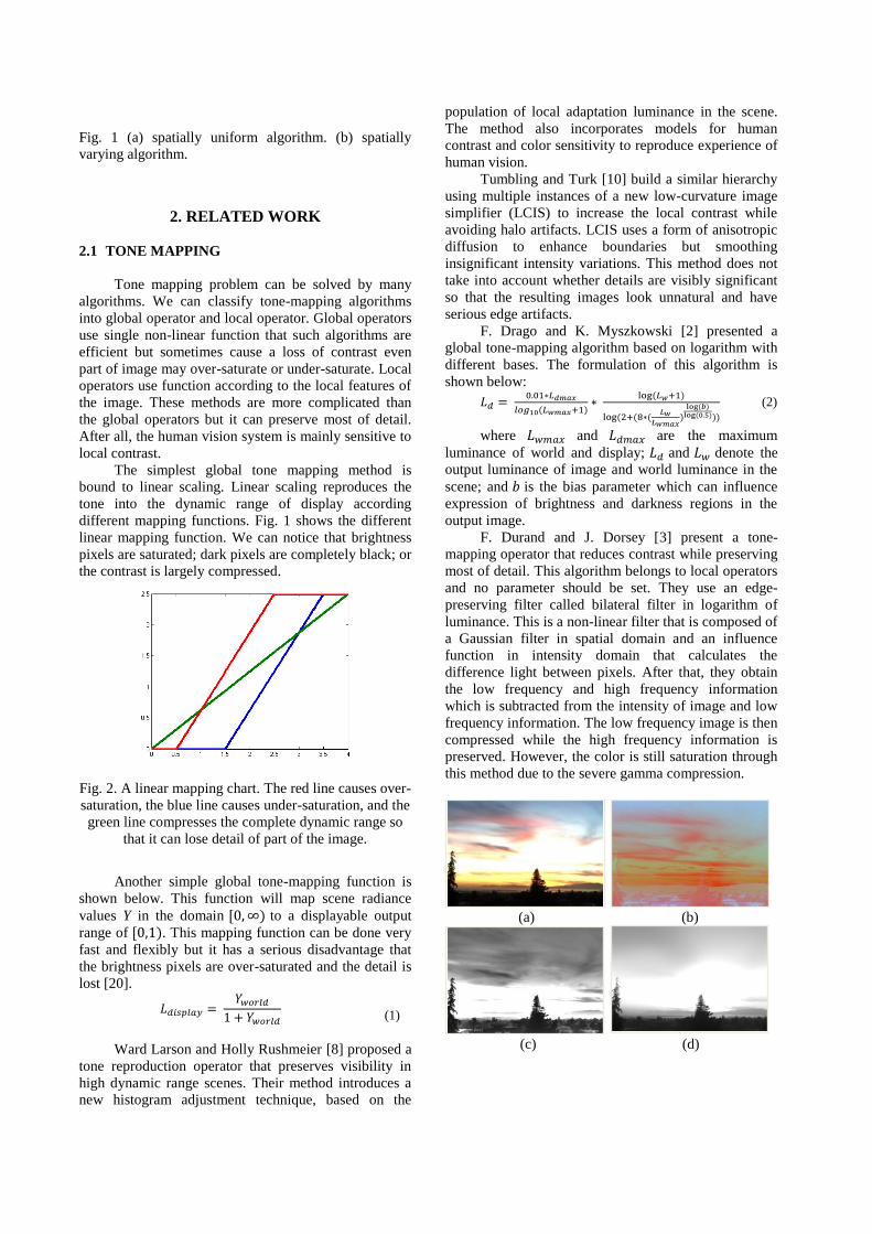
Fig. 1 (a) spatially uniform algorithm. (b) spatially
varying algorithm.
2. RELATED WORK
2.1 TONE MAPPING
Tone mapping problem can be solved by many
algorithms. We can classify tone-mapping algorithms
into global operator and local operator. Global operators
use single non-linear function that such algorithms are
efficient but sometimes cause a loss of contrast even
part of image may over-saturate or under-saturate. Local
operators use function according to the local features of
the image. These methods are more complicated than
the global operators but it can preserve most of detail.
After all, the human vision system is mainly sensitive to
local contrast.
The simplest global tone mapping method is
bound to linear scaling. Linear scaling reproduces the
tone into the dynamic range of display according
different mapping functions. Fig. 1 shows the different
linear mapping function. We can notice that brightness
pixels are saturated; dark pixels are completely black; or
the contrast is largely compressed.
Fig. 2. A linear mapping chart. The red line causes over-
saturation, the blue line causes under-saturation, and the
green line compresses the complete dynamic range so
that it can lose detail of part of the image.
Another simple global tone-mapping function is
shown below. This function will map scene radiance
values Y in the domain to a displayable output
range of . This mapping function can be done very
fast and flexibly but it has a serious disadvantage that
the brightness pixels are over-saturated and the detail is
lost [20].
(1)
Ward Larson and Holly Rushmeier [8] proposed a
tone reproduction operator that preserves visibility in
high dynamic range scenes. Their method introduces a
new histogram adjustment technique, based on the
population of local adaptation luminance in the scene.
The method also incorporates models for human
contrast and color sensitivity to reproduce experience of
human vision.
Tumbling and Turk [10] build a similar hierarchy
using multiple instances of a new low-curvature image
simplifier (LCIS) to increase the local contrast while
avoiding halo artifacts. LCIS uses a form of anisotropic
diffusion to enhance boundaries but smoothing
insignificant intensity variations. This method does not
take into account whether details are visibly significant
so that the resulting images look unnatural and have
serious edge artifacts.
F. Drago and K. Myszkowski [2] presented a
global tone-mapping algorithm based on logarithm with
different bases. The formulation of this algorithm is
shown below:
(2)
where and are the maximum
luminance of world and display; and denote the
output luminance of image and world luminance in the
scene; and is the bias parameter which can influence
expression of brightness and darkness regions in the
output image.
F. Durand and J. Dorsey [3] present a tone-
mapping operator that reduces contrast while preserving
most of detail. This algorithm belongs to local operators
and no parameter should be set. They use an edge-
preserving filter called bilateral filter in logarithm of
luminance. This is a non-linear filter that is composed of
a Gaussian filter in spatial domain and an influence
function in intensity domain that calculates the
difference light between pixels. After that, they obtain
the low frequency and high frequency information
which is subtracted from the intensity of image and low
frequency information. The low frequency image is then
compressed while the high frequency information is
preserved. However, the color is still saturation through
this method due to the severe gamma compression.
(a) (b)
(c) (d)
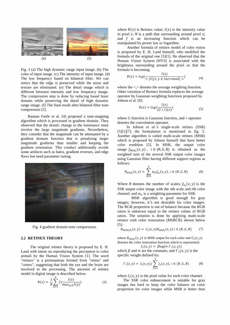
(e) (f)
Fig. 3 (a) The high dynamic range input image. (b) The
color of input image. (c) The intensity of input image. (d)
The low frequency based on bilateral filter. We can
notice that the edge is preserved while the noise and
texture are eliminated. (e) The detail image which is
different between intensity and low frequency image.
The compression step is done by reducing based layer
domain while preserving the detail of high dynamic
range image. (f) The final result after bilateral filter tone
compression [5].
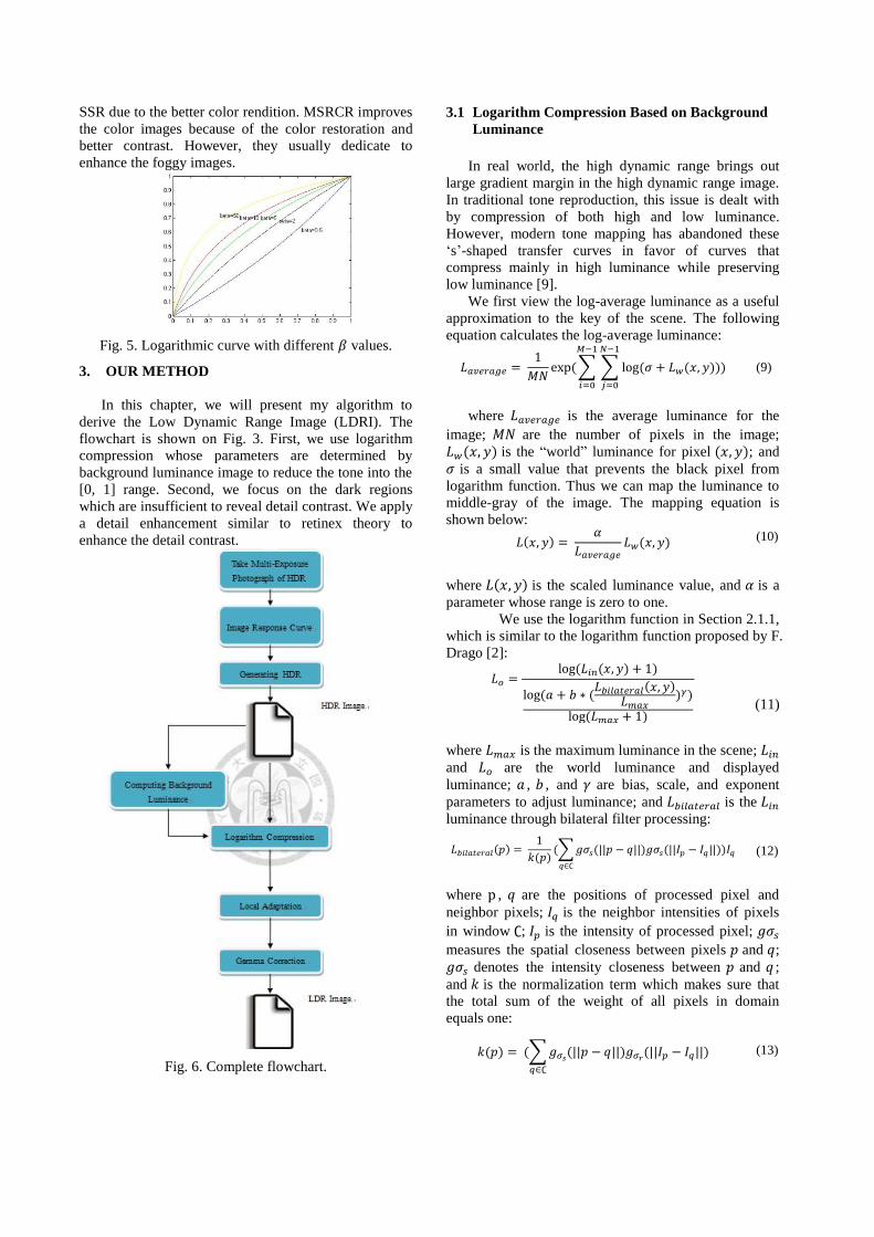
Raanan Fattle et al. [4] proposed a tone-mapping
algorithm which is processed in gradient domain. They
observed that the drastic change in the luminance must
involve the large magnitude gradients. Nevertheless,
they consider that the magnitude can be attenuated by a
gradient domain function that is penalizing larger
magnitude gradients than smaller and keeping the
gradient orientation. This conduct additionally avoids
some artifacts such as halos, gradient reverses, and edge
flaws but need parameter tuning.
Fig. 4 gradient domain tone compression.
2.2 RETINEX THEORY
The original retinex theory is proposed by E. H.
Land with intent on reproducing the perception to color
stimuli by the Human Vision System [1]. The word
"retinex" is a portmanteau formed from "retina" and
"cortex", suggesting that both the eye and the brain are
involved in the processing. The ancestor of retinex
model in digital image is described below:
∑
(3)
where is Retinex value; is the intensity value
in pixel ; is a path that surrounding around pixel ;
and is an increasing function which can be
manipulated by power law or logarithm.
Another formula of retinex model of color vision
is proposed by E. H. Land himself, who modified the
formula of the original one [5][1]. He observed that the
Human Vision System (HVS) is associated with the
brightness surrounding around the pixel so that the
formula is becoming:
(4)
where the <,> denotes the average weighting function.
Other variation of Retinex formula replaces the average
operator by Gaussian weighting functions proposed by
Jobson et al. [6]:
(5)
where G function is Gaussian function, and operator
denotes the convolution operator.
In Jobson et al.’s single-scale retinex (SSR)
[5][1][7], the formulation is mentioned in fig. 5.
Another algorithm is called multi-scale retinex (MSR)
which is proposed by Jobson himself that have better
color rendition [5]. In MSR, the output color
image , is obtained as the
weighted sum of the several SSR output color images
using Gaussian filter having different support regions as
follows:
∑
(6)
Where denotes the number of scales; is the
SSR output color image with the nth scale and color
channel; and is a weighting parameter for SSR.
MSR algorithm is good enough for gray
images; however, it’s not desirable for color images.
The RGB proportion is out of balance because the RGB
ratios is unknown equal to the retinex values of RGB
ratios. The solution is done by applying multi-scale
retinex with color restoration (MSRCR) shown below
[5]:
(7)
where is MSR output for each color and
denotes the color restoration function which is represented:
which and are the constants, and is the
specific weight defined by:
∑
(8)
where is the pixel value for each color channel.
The SSR color enhancement is suitable for gray
images but hard to keep the color balance on color
proportion for color images while MSR is better than
SSR due to the better color rendition. MSRCR improves
the color images because of the color restoration and
better contrast. However, they usually dedicate to
enhance the foggy images.
Fig. 5. Logarithmic curve with different values.
3. OUR METHOD
In this chapter, we will present my algorithm to
derive the Low Dynamic Range Image (LDRI). The
flowchart is shown on Fig. 3. First, we use logarithm
compression whose parameters are determined by
background luminance image to reduce the tone into the
[0, 1] range. Second, we focus on the dark regions
which are insufficient to reveal detail contrast. We apply
a detail enhancement similar to retinex theory to
enhance the detail contrast.
Fig. 6. Complete flowchart.
3.1 Logarithm Compression Based on Background
Luminance
In real world, the high dynamic range brings out
large gradient margin in the high dynamic range image.
In traditional tone reproduction, this issue is dealt with
by compression of both high and low luminance.
However, modern tone mapping has abandoned these
‘s’-shaped transfer curves in favor of curves that
compress mainly in high luminance while preserving
low luminance [9].
We first view the log-average luminance as a useful
approximation to the key of the scene. The following
equation calculates the log-average luminance:
∑ ∑
(9)
where is the average luminance for the
image; are the number of pixels in the image;
is the “world” luminance for pixel ; and
is a small value that prevents the black pixel from
logarithm function. Thus we can map the luminance to
middle-gray of the image. The mapping equation is
shown below:
(10)
where is the scaled luminance value, and is a
parameter whose range is zero to one.
We use the logarithm function in Section 2.1.1,
which is similar to the logarithm function proposed by F.
Drago [2]:
(11)
where is the maximum luminance in the scene;
and are the world luminance and displayed
luminance; , , and are bias, scale, and exponent
parameters to adjust luminance; and is the
luminance through bilateral filter processing:
∑
(12)
where , are the positions of processed pixel and
neighbor pixels; is the neighbor intensities of pixels
in window ; is the intensity of processed pixel;
measures the spatial closeness between pixels and ;
denotes the intensity closeness between and ;
and is the normalization term which makes sure that
the total sum of the weight of all pixels in domain
equals one:
∑
(13)
3.2 Retinex-Based Local Adaptation
After logarithm compression, we perform a
surround-based Retinex method to enhance detail. Here
is the following equation:
( ) (14)
where and are the displayed
luminance and luminance from Eq. (4.1.3); is a scale
parameter; is computed by convolving the
luminance with surround function; and
is computed by:
( )
(15)
where is a parameter that higher value causes high-
key images. Logarithm curve obeys the Weber-Fechner
law of Just-Noticeable Difference (JND) response in
human vision. Fig. 2 shows the logarithm curves with
different values.
Finally, we need to do the gamma correction, a
nonlinear operation used to encode and decode
luminance or tristimulus values in video or still image
systems.
4. EXPERIMENTAL RESULTS
(a) (b)
(c) (d)
(a) (b)
(c) (d)
(a)
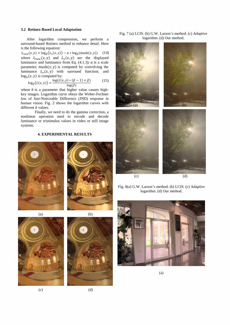
Fig. 7 (a) LCIS. (b) G.W. Larson’s method. (c) Adaptive
logarithm. (d) Our method.
Fig. 8(a) G.W. Larson’s method. (b) LCIS. (c) Adaptive
logarithm. (d) Our method.
(b)
(c)
(d)
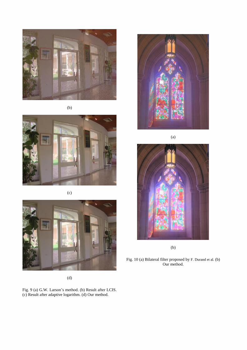
Fig. 9 (a) G.W. Larson’s method. (b) Result after LCIS.
(c) Result after adaptive logarithm. (d) Our method.
(a)
(b)
Fig. 10 (a) Bilateral filter proposed by F. Durand et al. (b)
Our method.
(a)
(b)
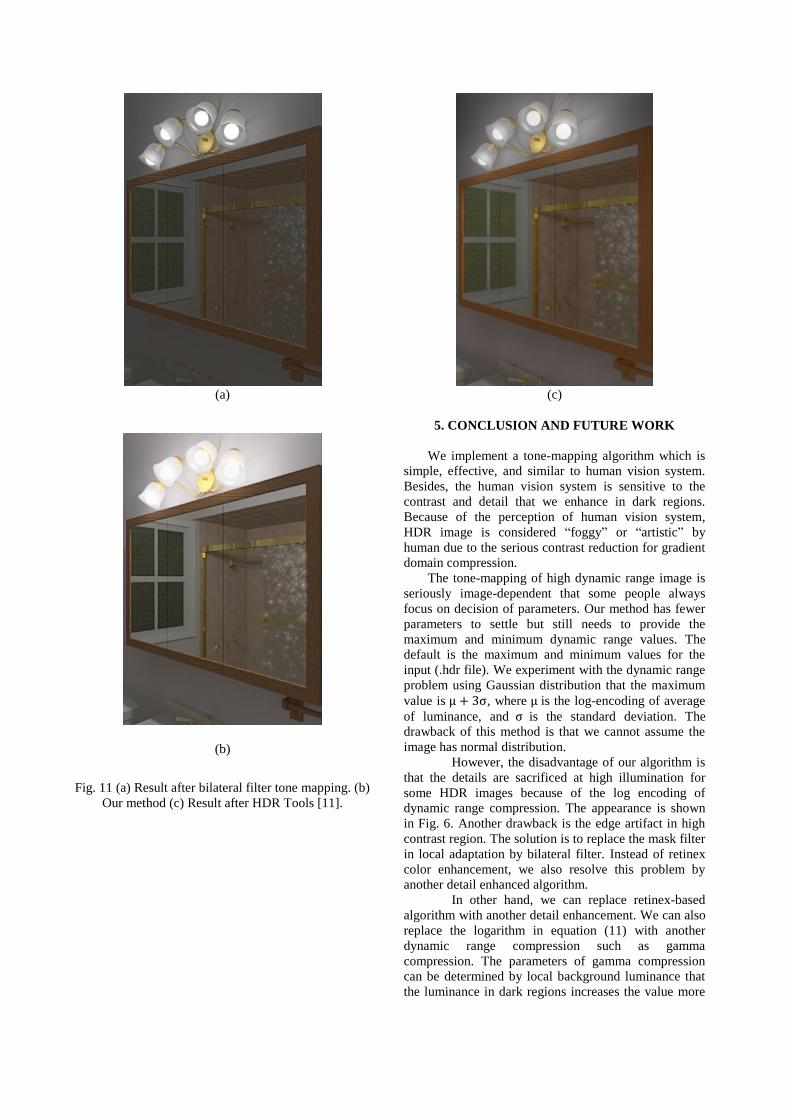
Fig. 11 (a) Result after bilateral filter tone mapping. (b)
Our method (c) Result after HDR Tools [11].
(c)
5. CONCLUSION AND FUTURE WORK
We implement a tone-mapping algorithm which is
simple, effective, and similar to human vision system.
Besides, the human vision system is sensitive to the
contrast and detail that we enhance in dark regions.
Because of the perception of human vision system,
HDR image is considered “foggy” or “artistic” by
human due to the serious contrast reduction for gradient
domain compression.
The tone-mapping of high dynamic range image is
seriously image-dependent that some people always
focus on decision of parameters. Our method has fewer
parameters to settle but still needs to provide the
maximum and minimum dynamic range values. The
default is the maximum and minimum values for the
input (.hdr file). We experiment with the dynamic range
problem using Gaussian distribution that the maximum
value is , where is the log-encoding of average
of luminance, and is the standard deviation. The
drawback of this method is that we cannot assume the
image has normal distribution.
However, the disadvantage of our algorithm is
that the details are sacrificed at high illumination for
some HDR images because of the log encoding of
dynamic range compression. The appearance is shown
in Fig. 6. Another drawback is the edge artifact in high
contrast region. The solution is to replace the mask filter
in local adaptation by bilateral filter. Instead of retinex
color enhancement, we also resolve this problem by
another detail enhanced algorithm.
In other hand, we can replace retinex-based
algorithm with another detail enhancement. We can also
replace the logarithm in equation (11) with another
dynamic range compression such as gamma
compression. The parameters of gamma compression
can be determined by local background luminance that
the luminance in dark regions increases the value more
than the luminance in bright regions but might cause the
color saturation due to the severe local light
compensation.
(a) (b)
REFERENCES [1] M. Bertalmío, V. Caselles, and E. Provenzi, “Issues
about Retinex Theory and Contrast Enhancement,”
International Journal of Computer Vision, Vol. 83, No.
1, pp. 101-119, 2009.
[2] F. Drago, K. Myszkowski, T. Annen, and N. Chiba,
“Adaptive Logarithmic Mapping for Displaying High
Contrast Scenes,” Proceedings of EUROGRAPHICS,
Granada, Spain, Vol. 22, No. 3, pp. 419-426, 2003.
[3] F. Durand and J. Dorsey, “Fast Bilateral Filtering for
the Display of High-Dynamic Range Images,” ACM
Transactions on Graphics, Vol. 21, No. 3, pp. 257-266,
2002.
[4] R. Fattal, D. Lischinski, and M.Werman, “Gradient
Domain High Dynamic Range Compression,” ACM
Transactions on Graphics, Vol. 21, pp. 249-256, 2002.
[5] D. J. Jobson, Z. Rahman, and G. A. Woodell, “A Multi-
Scale Retinex for Bridging the Gap Between Color
Images and the Human Observation of Scenes,” IEEE
Transactions on Image Processing, Vol. 6, pp. 965-976,
1997.
[6] D. J. Jobson, Z. Rahman, and G. A. Woodell,
“Properties and Performance of a Center/Surround
Retinex,” IEEE Transactions on Image Processing, Vol.
6, pp 451-462, 1997.
[7] E. H. Land, “The Retinex Theory of Color Vision,” The
Scientific American, Vol. 12, pp. 108-128, 1977.
[8] G. W. Larson, H. Rushmeier, and C. Piatko, “A
Visibility Matching Tone Reproduction Operator for
High Dynamic Range Scenes,” IEEE Transactions on
Visualization and Computer Graphics, Vol. 3, No. 4, pp.
291-306, 1977.
[9] E. Reinhard, M. Stark, P. Shirley, and J. Ferwerda,
“Photographic Tone Reproduction for Digital Images,”
Proceedings of ACM SIGGRAPH, San Antonio, Texas,
Vol. 21, No. 3, pp. 267-276, 2002.
[10] J. Tumblin and G. Turk, “LCIS: A Boundary Hierarchy
for Detail-Preserving Contrast Reduction.” Proceedings
of ACM SIGGRAPH Annual Conference, Los Angeles,
California, pp. 83-90, 1999.
[11] Toyota Technological Institute at Chicago, “HDR
Tools,”
http://ttic.uchicago.edu/~cotter/projects/hdr_tools,
2011.
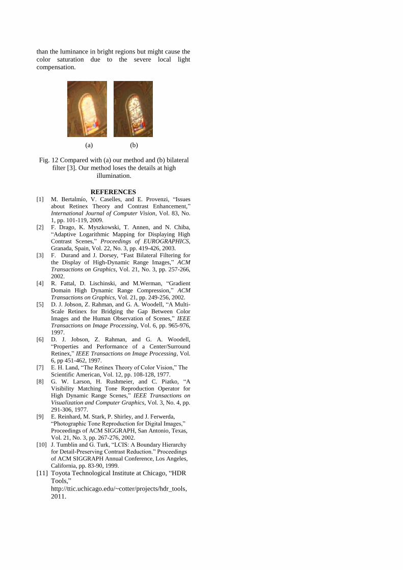
Fig. 12 Compared with (a) our method and (b) bilateral
filter [3]. Our method loses the details at high
illumination.