a theoretical and experimental study of unsteady flow ... x* definition of symbols definition speed...
TRANSCRIPT

NASA TECHNICAL NOTE
A THEORETICAL A N D STUDY OF UNSTEADY I N A LUDWIEG TUBE
EXPERIMENTAL FLOW PROCESSES WIND TUNNEL
by John D. Warmbrod
George C. Marshall Space Flight Center Marsha ZZ, A Za.
N A T I O N A L A E R O N A U T I C S A N D S P A C E A D M I N I S T R A T I O N W A S H I N G T O N , D . C. - N O V E M B E R 1 9 6 9
https://ntrs.nasa.gov/search.jsp?R=19700001406 2018-06-23T16:42:16+00:00Z
TECH LIBRARY WFB, "I
I
1. Report No. 2. Govwrnment Accession No. NASA TN D-5469 I
4. T i t l e and Subtitle A Theoretical and Experimental Study of Unsteady Flow Processes in a Ludwieg rube Wind Tunnel 7. Author(.) John D. Warmbrod
16. Abstroct The application of a numerical procedure generally re fer red to as the
method of character is t ics to calculate the nonsteady discharge of compressed x i r through a Ludwieg tube type of wind tunnel is presented. The mathemati- cal model that underlies the numerical procedure assumes the flow through the wind tunnel to be time-dependent, one-dimensional, and compressible. The theoretical resul ts presented were obtained f rom a computer program developed for this problem. a reas , contact surfaces , shock waves, and the interaction and reflection of contact surfaces and shock waves are included in the computer program. The theoretical results are compared with static and total p ressures measured in a Ludwieg tube wind tunnel that has recently begun preliminary operation at MSFC. Good agreement between theory and experiment is achieved for the cases in which the flow in the test section was subsonic. Only fair agreement between the one-dimensional theory and experiment was achieved in the super sonic test sections. This difference is believed to be attributed to the two- dimensional character of the flow and the extensive flow separation that occurs
Diaphragm rupture, variations in cross-sectional
9. Performing Orgmirot ion Name and Address
George C . Marshall Space Flight Center Marshall Space Flight Center, Alabama 35812
-
2 . Sponsoring Agency Noms and Address
Xational Aeronautics and Space Adminis t ra t ion Jashington, D. C. 20546
3. Recipiwnt's Cotolog No.
5. Report Data November 1969
~~~
6. Performing Orgonirotian Code
8. Performing Organization Report No.
M i 5 1 IO. Work Unit No.
933-50-07-00-62 11. Controct or Grant No.
13. Type o f Report and Pwriod Covered
Technical Note
15. Supplementary Notes
Prepared by Aero-Astrodynamics Laboratory, Science and Engineering Directorate

I -...-.,,...

TABLE OF CONTENTS
Page
SUMMARY I . . . . . . . . . . . . . . . . . . . . . . . . . . . . . . . . . . . . . . . . .
I
2
4 T H E O R E T I C A L A N A L Y S I S . . . . . . . . . . . . . . . . . . . . . . . . . . . . . . .
8 COMPARISON OF THEORETICAL WITH EXPERIMENTAL RESULTS . . 12 CONCLUSIONS . . . . . . . . . . . . . . . . . . . . . . . . . . . . . . . . . . . . . . .
REFERENCES 17
INTRODUCTION . . . . . . . . . . . . . . . . . . . . . . . . . . . . . . . . . . . . . . DESCRIPTION O F TEST EQUIPMENT . . . . . . . . . . . . . . . . . . . . . . .
. . . . . . . . . . . . . . . . . . . . . . . . . . . . . . . . . . . . . . .
iii
I
LIST OF ILLUSTRATIONS
Figure
1.
2.
3 .
4.
5.
6.
7.
Title
High Reynolds number test equipment. . . . . . . . . . . . . . . Wave, diagram for a Mach 2 nozzle . . . . . . . . . . . . . . . .
Time dependence of test section static pressure for = 2 . 0 . . . . . . . . . . . . . . . . . . . . . . . . . . . . . .
M~~~~
Page
3
7
9
Time dependence of static pressure and Mach number in the subsonic ( M = 0.7) test section of a TEST Ludwieg tube pilot facility . . . . . . . . . . . . . . . . . . . . . . l i
= 0.47 . . . . . . . . . . . . . . . . . 13 TEST Wave diagram for M
Time dependence of static pressure in the subsonic = 0.47) test section of Ludwieg tube . . . . . . . . . 14
( M~~~~
Time dependence of total pressure in the settling chamber . . . . . . . . . . . . . . . . . . . . . . . . . . . . . . . . . . 15
iv
Symbol
a
A
C P
LO
M~~~~
P
pC
Pt
P
Q
R
S
S
t
t : k
T
U
X
X*
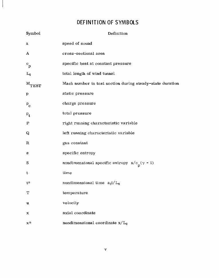
DEFINITION OF SYMBOLS
Definition
speed of sound
cross-sectional a rea
specific heat at constant pressure
total length of wind tunnel
Mach number in test section during steady-state duration
static pressure
charge pressure
total pressure
right running characteristic variable
left running characterist ic variable
gas constant
specific entropy
nondimensional specific entropy s / c ( y - 1)
time
nondime ns i onal ti me a ot/ Lo
temperature
velocity
axial coordinate
nondimensional coordinate x/Lo
P
V

Symbol
Y
P
Subscripts
0
Superscripts
*
DEFINITION OF SYMBOLS (Concluded) Definition
rat io of specific heats
density
reference conditions
nondimensional quantities
vi
A THEORETICAL AND EXPERIMENTAL STUDY OF UNSTEADY FLOW PROCESSES I N A LUDW IEG TUBE WIND TUNNEL
SUMMARY
The application of a numerical procedure generally referred to as the method of characterist ics to calculate the nonsteady discharge of compressed air through a Ludwieg tube type of wind tunnel is presented. The mathematical model that underlies the numerical procedure assumes the flow through the wind tunnel to be time-dependent, one-dimensional, and compressible. The theoretical resul ts presented were obtained from a computer program developed for this problem. Diaphragm rupture, variations in cross-sectional areas, contact surfaces, shock waves, and the interaction and reflection of contact surfaces and shock waves are included in the computer program. The theoreti- cal results are compared with static and total pressures measured in a Ludwieg tube wind tunnel that has recently begun preliminary operation at MSFC. Good agreement between theory and experiment is achieved for the cases in which the flow in the test section w a s subsonic. Only fair agreement between the one- dimensional theory and experiment was achieved in the supersonic test sections. This difference is believed to be attributed to the two-dimensional character of the flow and the extensive flow separation that occurs in the supersonic nozzles during the ear ly development of the flow.
INTRODUCTION
To support present and future missions of our extremely large and fast space vehicles, it is necessary to simulate high Reynolds numbers in our wind tunnel testing programs. Ludwieg [I] first proposed the principle of the pressure tube wind tunnel and supervised the construction of such a wind tunnel [ 21 at the Aerodynamische Versuchsanstalt in Gottingen, where a facility of this type has been successfully operated [ 3 ] . Basically, this type of wind tunnel consists of a long tube filled with high pressure gas, a nozzle, a test section, and an outlet into the atmosphere o r some so r t of emptying reservoir . The high pressure gas is generally sealed downstream of the test section by a diaphragm. When the diaphragm ruptures, the high pressure gas moves through the test section and establishes, after a certain start time, a period of constant
property flow. The attractive characterist ic of this type of wind tunnel is the high Reynolds number flows that can be produced in the test section. References 4 and 5 describe the operating principle and repor t some measurements of a "Ludwieg Tube" wind tunnel constructed at the Royal Armament Research and Development Establishment in England during 1957. Davis [ 6,7] presents a feasibility study and some measurements made in a pilot model of a Ludwieg tube wind tunnel that was to be built at Marshall Space Flight Center in 1968.
Analytical methods for solving time -dependent one-dimensional flow through a duct have been available for some time [ 8, 91. Because of the compli- cated wave processes that occur during the ear ly stages of expansion flow through a duct of varying c ross section, the automation of the analytical methods has been virtually ignored. References 10 and 11 report recent resul ts f rom computer programs that solve the transient one-dimensional flow through ducts of varying c ross sections by a numerical procedure referred to as the "method of characterist ics. ? t Reference 12 presents resul ts based upon an implicit finite difference procedure that solves the compressible gas flow through a duct of constant c r o s s section.
This paper presents a comparison of measured and theoretical resul ts for the flow of air through the high Reynolds number wind tunnel a t Marshall Space Flight Center. The method and computer program reported in Reference 10 were used to produce the theoretical resul ts presented. results are measurements obtained from the pilot model tests and during initial runs of the Ludwieg tube tunnel, which has recently begun shakedown operation at MSFC.
The experimental
DESCRIPTION OF TEST EQUI PMENT
To obtain data for high Reynolds number flows, MSFC proposed in 1965 the construction of a relatively inexpensive short duration wind tunnel based upon a concept proposed by Ludwieg in 1955. A small pilot model of this type of wind tunnel was constructed in 1967, and resul ts f rom testing in this model facility were reported by Davis [ 61. Construction of the wind tunnel at MSFC was completed in April of 1969, and the operation of this equipment subsequently began. Figure 1 is a pictorial drawing of the major components that make up the wind tunnel. The diaphragm that initially separates the high pressure and low pressure reservoi rs is located downstream of the test section. initiated by cutting the diaphragm, which is composed of sheets of mylar
Flow is
2

w Figure 1. High Reynolds number test equipment.

supported on a cruciform frame. The supply tube is 378 feet long with an inner diameter of 52 inches. A settling chamber separates the supply tube and the nozzle. Its purpose is to reduce the effects of the boundary layer, which grows with time along the supply tube, and to slow the flow before it enters the nozzle, thus tending to improve the quality of the flow before it en ters the nozzle and test section. Downstream of the settling chamber is the nozzle section. A t present, four nozzles have been designed: a sonic nozzle used in all subsonic test cases, and three supersonic nozzles that produce Mach numbers of I. 4, I. 7, and 2 . 0 in the test section. For testing at subsonic Mach numbers, a sonic nozzle is installed in the nozzle section, and any particular subsonic Mach number between 0 . 2 5 - 0.77 in the’test section can be obtained by a proper setting of the choking flaps, which are located immediately downstream of the test section. Each supersonic Mach number in the test section requires insertion of an appropriate nozzle in the nozzle section. The nozzles for the supersonic Mach number cases were designed from the results of a two- dimensional method of characterist ics satisfying the condition of uniform flow at the nozzle exit plane. Testing at transonic Mach numbers will be conducted in a special transonic test section now under construction. Immediately down- s t ream of the nozzle is the test section, which has an inner diameter of 32 inches. Reynolds numbers up to approximately 2 . 0 x I O 8 per foot for a Mach number of I. 4 in the test section can be attained when the supply tube is charged to its maximum pressure of 700 lb/in.2. Downstream of the test section follow the model support, diaphragm, spool section, diffusers, and an emptying reservoir, which is a large sphere that slowly discharges the high pressure gas into the atmosphere. A large muffler is located at the outlet of this sphere to attenuate the sound of the discharging gas.
Operation of this equipment w a s begun in April of 1969. Thus f a r , only shakedown runs a t low charge temperatures for subsonic Mach numbers have been conducted. and static pressures in the test section have been measured, and a r e compared with theoretical results in a later section of this report.
Total p ressures and temperatures in the settling chamber
THEORETICAL ANALYSIS
The theoretical resul ts presented in this report are based upon the assumption that the flow of gas through the duct is time-dependent, one- dimensional, and compressible. The differential equations in Eulerian form, which describe the flow based upon these assumptions, a r e a s follows:
4
.. -. . . .. . .. .

Continuity
Momentum
State
P y P YRT
First law of thermodynamics
P In - s - s o = c 1 n - - c T - Y - i P To P Y Po
Since the resul ts appearing in this report do not include wall friction effects o r mass removal from the duct, for example, in a transonic section with porous walls, the t e rms that account for these effects a r e not included in the above equations. The partial differential equations (I) through (4) are of the hyperbolic type and can readily be solved by a numerical procedure referred to as the method of characterist ics. For a detailed derivation of the charac- terist ic equations from the partial differential equations and a description of the method in which the characterist ic equations are then solved, the reader should refer to Reference I O . Briefly, the method consists of deriving finite difference equations from the partial differential equations so that certain parameters, usually called Riemann or characterist ic variables, can be solved by a step-by-step procedure along particular charactersit ic curves in the plane of the independent variables. For the problem a t hand, the parameters are re fer red to as P ( the right running characterist ic), Q ( the left running characteristic) , and S (the entropy) , which follows the particle path in the x, t plane. In regions where the Q characterist ics travel toward the left, the flow is subsonic; vertically, the flow is sonic; and toward the right, the flow is supersonic. Whenever two curves of the same family (either P or Q ) meet, a discontinuity in the pressure exists at this point. A boundary in the flow is thus established, and this boundary is defined as a normal shock wave. Two types of shock waves can therefore occw, either a P shock (converging of the P characterist ics) or a Q shock (converging of the Q characterist ics)
5
Since it is assumed that changes of the flow variables ac ross a shock wave take place instantaneously, the steady-state relationship between flow variables on each side of the shock can be used. The equations that relate the flow variables upstream and downstream of a stationary normal shock are generally referred to as the Rankine-Hugoniot equations. The mathematical process at a shock point is to match the normal shock solution with the characterist ic solution. Details of the matching procedure and the normal shock equations are published in Reference 10.
Another discontinuity that can occur is referred to as a "contact surface. I '
A contact surface is defined as a boundary through which no f lux of mat ter can pass. It is an interface or boundary in the x , t plane in which the conditions of equal velocity and pressure on each side are satisfied, with, however, other properties being discontinuous. An example of this type of discontinuity is the path of the interface separating two different gases that are flowing through a duct or the path of the interface between the same gas at different entropy levels in the x , t plane. At a contact surface point, the mathematical process is to match the characterist ic solution with the boundary conditions on each side of the point.
It can easily be seen that possibilities exist for discontinuities to inter- sect with one another. Such possibilities are shocks of like families intersect- ing, shocks of unlike families intersecting, and shock and contact-surface inter- secting. Although the general methods for handling these interactions a r e similar, each case requires somewhat different calculation procedures.
A computer program to calculate the complete flow field for the Ludwieg tube problem with time was constructed. The calculation begins at diaphragm rupture and automatically solves the flow phenomenon that occurs for time-dependent, one-dimensional, compressible flow of gas through the duct.
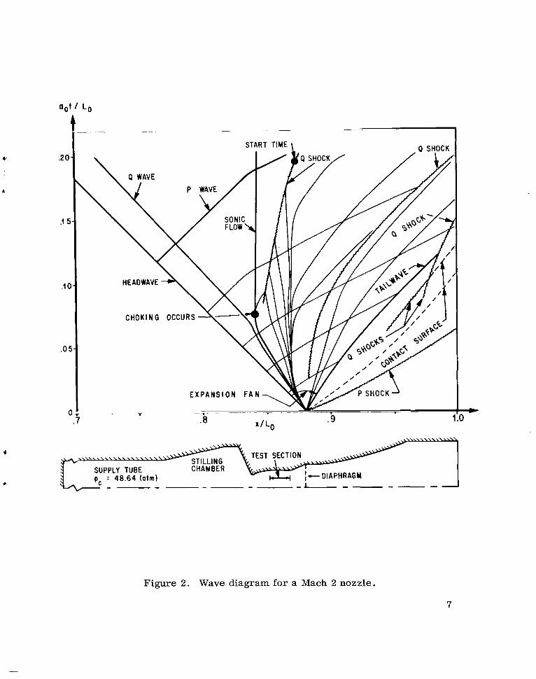
Figure 2 shows a wave diagram of the calculated results for the Ludwieg tube wind tunnel with a Mach 2 nozzle mounted upstream of the test section. When the diaphragm is ruptured, the high pressure gas on the left expands and compresses the low pressure gas on the right, creating a P shock wave that travels downstream through the undisturbed gas. Proceeding downstream behind the P shock is a contact surface, which is the interface between the gas particles that were initially in contact with each side of the diaphragm. Also created at diaphragm rupture is an expansion fan that is bounded on the left by the headwave and on the rightby a tailwave. The waves shown in the expansion fan belong to the family of left running o r Q characterist ic waves.
6
aot I L o
1
.20.
.I 5
.I 0
.o 5
C 7
E X P A N S I
~ -
.6 -
SUPPLY TU BE CHAMBER = 48.64 (otm) ----- -1-----
Figure 2. Wave diagram for a Mach 2 nozzle.
7

In Figure 2 can be seen that par t of the fan which t ravels upstream through the nozzle and into the supply tube before choking at the nozzle throat occurs. After the throat chokes, no more expansion o r Q characterist ic waves can pass through the throat position. Subsequently, sonic flow is established at the nozzle throat, as illustrated by the vertically running Q characterist ic curve in the wave diagram. Immediately after choking, a Q shock is formed down- s t ream of the nozzle throat. This shock wave, which becomes stronger as it travels through the expanding portion of the nozzle, is eventually swept through the test section, leaving behind it a period of steady flow. Along with the P shock that was created at diaphragm rupture, a total of four Q shocks were formed within the duct during the time under consideration. A few selected P characterist ics are shown in the diagram to i l lustrate the grid of characteris- t ics on the x, t plane. No physical significance is rendered by the direction of the P characterist ics, whereas, the direction of the Q characterist ics i l lustrates the local flow regimes.
The method developed to calculate the time-dependent solution of the gas flow properties in the Ludwieg tube wind tunnel employs a step-by-step procedure that marches at a constant time interval of A t in the time direction. For the reader to gain some insight into the practicality of this procedure, let us return to Figure 2. The non-dimensional time interval used in calculating this wave diagram was 0.001. There was approximately a total of 20 000 points that were calculated, consuming 27 minutes of CDC 3200 computer time.
COMPARISON OF THEORETI CAL W I T H EXPERIMENTAL RESULTS
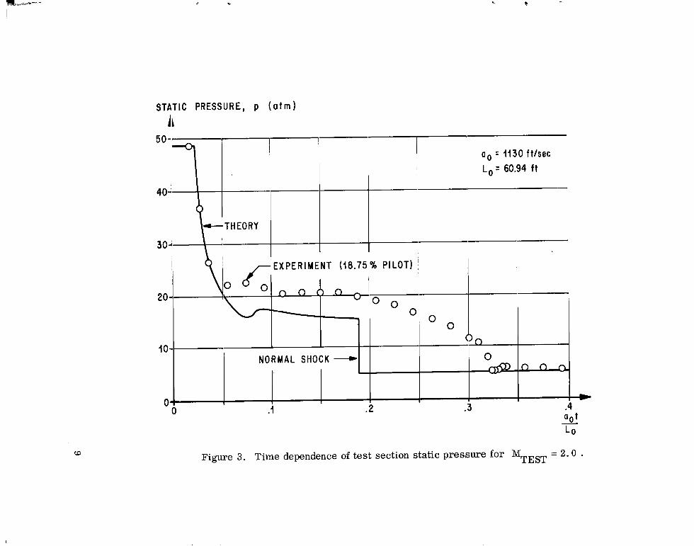
Figure 3 presents the time-dependent behavior of the static pressure a t a location in the tes t section that was calculated from the one-dimensional analysis for the 18.75-percent pilot model of the Ludwieg tube wind tunnel. The pilot model did not include a settling chamber. The experimental data were obtained from tests conducted in the pilot facility a t MSFC.. For this case, a supersonic nozzle is mounted upstream of the test section s o that flow of gas at a Mach number of 2 is established during the steady-state period. First, the behavior of the static pressure in the test section that resul ts from the theoretical analysis will be discussed. Since the settling chamber has very little effect on the flow properties in the supersonic test section, the wave diagram shown in Figure 2 will be referred to when explaining the resul ts shown in Figure 3 . in the wave diagram shown in Figure 2, it is seen that flow will begin at t:: = 0.02 upon ar r iva l of the expansion fan. The pressure immediately
Following the time dependence of the flow at x::: = 0.86
8
.
E X P E R I M E N T (18.75 % PILOT)
O O
10- NORMAL SHOCK -
c
0
0 ---
I I
Figure 3.
w
Time dependence of test section static pressure for MTEST = 2 . 0 .
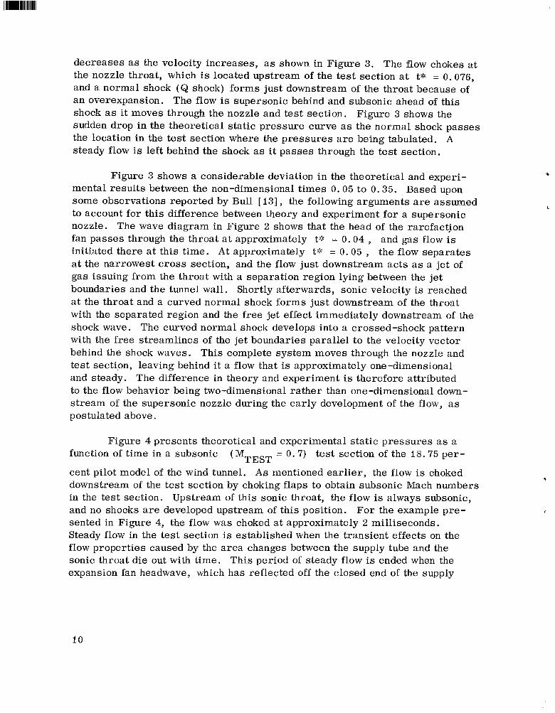
decreases as the velocity increases, as shown in Figure 3. The flow chokes at the nozzle throat, which is located upstream of the test section at t* = 0.076, and a normal shock ( Q shock) forms just downstream of the throat because of an overexpansion. The flow is supersonic behind and subsonic ahead of this shock as it moves through the nozzle and test section. Figure 3 shows the sudden drop in the theoretical static pressure curve as the normal shock passes the location in the test section where the pressures are being tabulated. A steady flow is left behind the shock as it passes through the test section.
Figure 3 shows a considerable deviation in the theoretical and experi- mental resul ts between the non-dimensional times 0.05 to 0.35. Based upon some observations reported by Bull [ 131, the following arguments are assumed to account for this difference between theory and experiment for a supersonic nozzle. The wave diagram in Figure 2 shows that the head of the rarefaction fan passes through the throat a t approximately t:: = 0.04 , and gas flow is initiated there at this time. A t approximately t::: = 0.05 , the flow separates at the narrowest c ros s section, and the flow just downstream acts as a jet of gas issuing from the throat with a separation region lying between the jet boundaries and the tunnel wall. Shortly afterwards, sonic velocity is reached at the throat and a curved normal shock forms just downstream of the throat with the separated region and the free jet effect immediately downstream of the shock wave. The curved normal shock develops into a crossed-shock pattern with the free streamlines of the jet boundaries parallel to the velocity vector behind the shock waves. This complete system moves through the nozzle and test section, leaving behind it a flow that is approximately one-dimensional and steady. The difference in theory and experiment is therefore attributed to the flow behavior being two-dimensional ra ther than one-dimensional down- s t ream of the supersonic nozzle during the ear ly development of the flow, as postulated above.
Figure 4 presents theoretical and experimental static pressures as a = 0.7) test section of the 18.75 per- function of time in a subsonic
cent pilot model of the wind tunnel. A s mentioned earlier, the flow is choked downstream of the test section by choking flaps to obtain subsonic Mach numbers in the test section. Upstream of this sonic throat, the flow is always subsonic, and no shocks are developed upstream of this position. sented in Figure 4, the flow was choked at approximately 2 milliseconds. Steady flow in the test section is established when the transient effects on the flow properties caused by the area changes between the supply tube and the sonic throat die out with time. This period of steady flow is ended when the expansion fan headwave, which has reflected off the closed end of the supply
( M ~ ~ ~ ~
For the example pre-
i o

, c
MA
1.0
0.8
0.6
0.4
0.2
0
NO.
STATIC PRESSURE ( a t m )
50
EXPERIMENT (18.75% PILOT) T H EORY
40 -
20- 30L I I I
10- I
I m 0 4 2 3 4 5 6 7 8
TIME (milliseconds) 0
Figure 4. Time dependence of static pressure and Mach number in the subsonic ( MTEsT = 0 .7 ) test section of a Ludwieg tube pilot facility.
!

tube, re turns to the test section. Thus, a long supply tube is essential for a long testing time. well with the measured data for the subsonic test section;
Figure 4 shows that the theoretical resul ts agree extremely
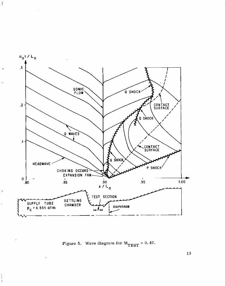
Figure 5 presents a wave diagram for the Ludwieg tube wind tunnel for = 0.47) . Only shock waves, contact surfaces, TEST a subsonic test case ( M
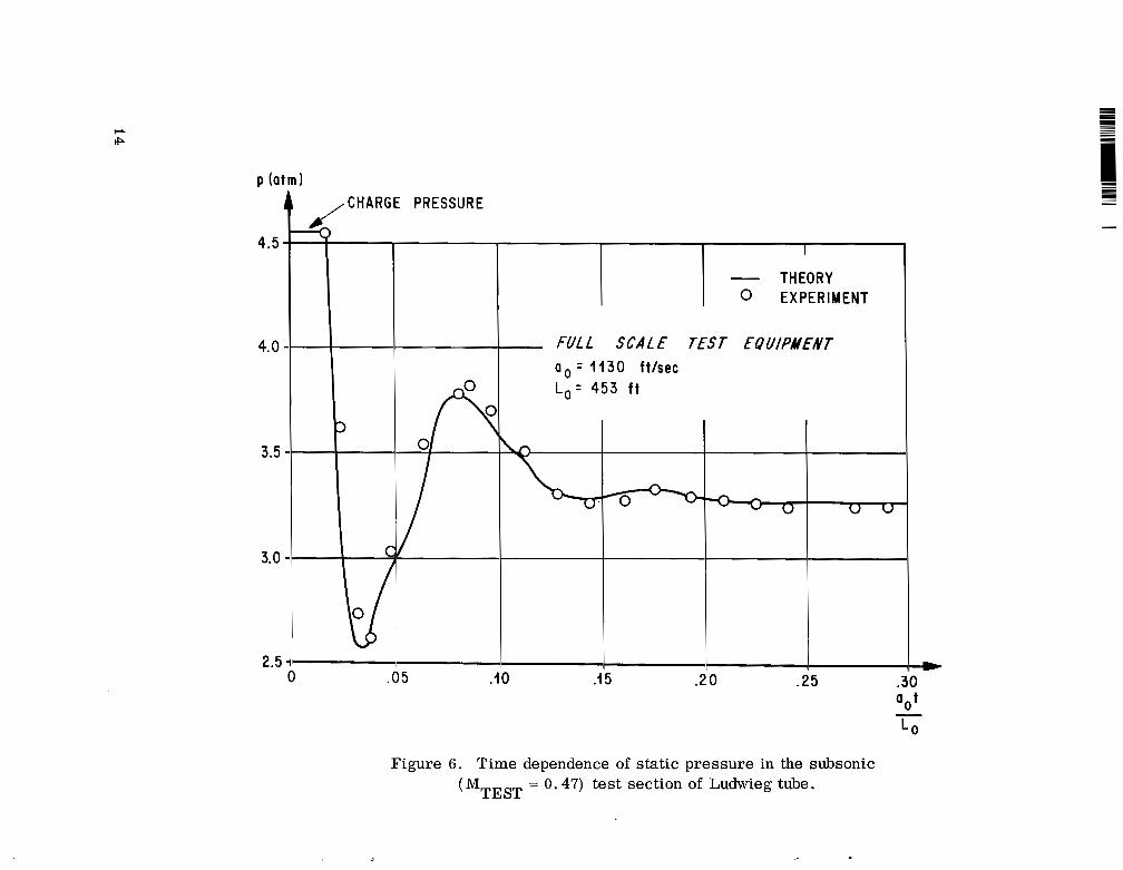
and selected Q characterist ics are shown in the diagram. Figure 6 shows the theoretical and experimental static pressures that were measured and calculated at x* = 0.891 in the test section for this case. The measured data were obtained during initial runs of the wind tunnel, which has recently begun pse- liminary operation. A s in the case for the pilot model (Fig. 4) , the results from the one-dimensional theory agree quite well with the static pressure measurements made in the test section of the large tunnel.
Since energy is not conserved in an unsteady expansion, the stagnation conditions through the nozzle decrease with time from the storage conditions until a steady state is reached. Figure 7 presents both calculated and measured total pressures that were made in the middle of the settling chamber. The hump in the total pressure curve is caused by the cross-sectional a rea changes of the settling chamber. This figure also shows good agreement between theory and experiment.
CONCLUSIONS
The application of a numerical procedure reported in Reference 1 0 for calculating the nonsteady discharge of compressed air through a Ludwieg tube type of wind tunnel has been presented. The mathematical model that underlies the numerical procedure, generally referred to a s the method of characteristics, assumes the flow through the wind tunnel to be time-dependent, one-dimensional, and compressible. The theoretical resul ts presented were obtained from a computer program that was developed for this problem. Diaphragm rupture, variations in c ross sectional areas, contact surfaces, shock waves, and the interaction and reflection of contact surfaces and shock waves are included in the computer program. The theoretical resul ts are compared with static and total pressures measured in a Ludwieg tube wind tunnel that has recently begun preliminary operation at MSFC. A s Figures 4 and 6 show, good agreement between theory and experiment is achieved for the cases in which the flow in the test section was subsonic. Only fair agreement between the one-dimensional
12
I EXPANSION FAN^ 0: - 1
.80 .85 .90 .95 1.00
TEST SECTION SETTLING
SUPPLY TUBE CHAMBER p, = 4 . 5 5 1 a t m I DIAPHRAGM
- -I- --
Figure 5. Wave diagram for MTEST = 0.47.
13
P ( a t m )
2.5 *--I---- .I 5 .20 .25 .30 0 .05 .IO
4.5
4.0
3.5
3.0
PRESSURE
THEORY - I 0 EXPERIMENT
FULL SCAL€ T€ST €QUlPAt€NT a o = 1130 f t /sec
1 T Figure 6 . Time dependence of static pressure in the subsonic
= 0.47) test section of Ludwieg tube. ( M ~ ~ ~ ~

4.5 -
4.0
3.5
pc = 4 . 5 5 1 a t m
~ " I U
. 2 .3 a,t I L o
Figure 7. Time dependence of total pressure in the settling chamber.
theory and experiment was achieved in the supersonic test section, as illustrated in Figure 3. This difference is believed to be attributed to the two-dimensional character of the flow and the extensive flow separation that occurs in the super- sonic nozzle during the ear ly development of the flow.
George C. Marshall Space Flight Center National Aeronautics and Space Administration
Marshall Space Flight Center, Alabama 35812 933- 50-0 7- 00-6 2
16
r
REFERENCES
I
I. Ludwieg, H. : Der Rohrwindkanal. , Zeitschrift f k Flugwissenschaften, Jahrgang 3, Heft 7, July 1955, p. 206.
2. Ludwieg, H. : Tube Wind Tunnel - A Special Type of Blowdown Tunnel. North Atlantic Treaty Organization Advisory Group for Aeronautical Research and Development, Report 143, July 1957.
3. Hottner, T . H. : Aerodynamische Untersuchungen a n Kegeln bei hohen Ueber s cha llge schwindigkei ten im Rohrwindkanal . Z ei tschrift ffir Flugwissenschaften, 15, Heft I , 1967, (a l so NASA Acc. No. N66-24826) .
4. Cox, R . N. : Discussion Following the Presentation of Papers on Hypersonics. AGARD Reports 132-147, July 1957, p. 28.
5. Cable, A. J . ; and Cox, R . N.: The Ludwieg Pressure-Tube Super- sonic Wind Tunnel. Aeron. Quart. , May 1963, pp. 143-157.
6. Davis, J. W. ; and Gwin, H. S. : Feasibility Studies of a Short Duration High Reynolds Number Wind Tunnel. NASA TM X-53571, Jan. 1967.
7. Davis, J. W. : A Shock Tube Technique for Producing Subsonic, Transonic, and Supersonic Flows With Extremely High Reynolds Numbers. AIAA Sixth Aerospace Science Meeting, Jan. 1968, AIAA Paper No. 68-18.
8. Rudinger, G. : Wave Diagrams for Nonsteady Flow in Ducts, D. Van Nostrand Co., Inc. , 1955.
9. Oswatitsch, K. : G a s Dynamics. Academic Press Inc. , 1956.
I O . Warmbrod, J. D. ; and Struck, H. G. : Application of the Characteristic Method in Calculating the Time Dependent, One Dimensional, Compressible Flow in a Tube Wind Tunnel. Aug. 1968.
NASA TM X-53769,
11. Culotta, A. J. : A Computer Program for the Solution of Unsteady Flow Fields in Expansion Tunnels or Shock Tunnels by the Method of Characteristics. AIAA Sixth Aerospace Science Meeting, Jan. 1968, AIAA Paper No. 68-52.
17

REFERENCES (Concluded)
12. Watts, J. W. ; and von Rosenberg, D. U. : A Numerical Solution of a Transient Shock Wave Problem. Chem. Eng. Science, vol. 24, 1969, pp. 49-56.
13. Bull, G. V. : Starting Processes in an Intermittent Supersonic Wind Tunnel, UTIA Report No. 12, University of Toronto, Feb. 1951.
18 NASA-Langley, 1969 - 12 M I 51

NATIONAL AERONAUTICS AND SPACE ADMINISTRATION WASHINGTON, D. C. 20546
OFFICIAL BUSINESS FIRST CLASS MAIL
POSTAGE AND FEES PAID NATIONAL AERONAUTICS AND
SPACE ADMINISTRATION
POSTMASTER: If Undeliverable (Section 158 , ' Postal Manual) Do Not Return
- --
. _11
"The eer.oiinitticnl mad space nctitiities of the United Stntes shnll be [ condzkted so as t o contribute . . , t o the expansiou of hicman kizorul- edge kif @henome?rn in. the ntutosphere aiad space. The Administration shnll.pr.oi,ide ' for the widest prncticnble atid appropriate disseiiiiaa!iora of i&for.ointioa I . coizcerning its nctivities nitd the results thereof."
' -NATIONAL AERONAUTICS AND SPACE ACT OF 1958 .\
NASA SCIENTIFIC AND TECHNICAL PUBLICATIONS
TECHNICAL REPPRTS: Scientific and technical infor$ation'considered important, complete, and a 1a;ting contribution to existing knowledge.
TECHNICAL NOTES: Information less broad in scope but nevertheless of importance as a contribution to existing knowledge.
TECHNICAL MEMORANDUMS: Information receiving limited distribution because of preliminary data, security classifica- tion. or other reasons.
CONTRACTOR REPORTS: Scientific and technical information generated under a NASA contract or grant and considered an important contribution to existing knowledge.
TECHNICAL TRANSLATIONS: Information piiblished in a foreign language considered to merit NASA distribution in English.
SPECIAL PUBLICATIONS: Information derived from or of value to NASA activicies. Publications include conference proceedings, monographs, data compilations, handbooks, sourcebooks, and special bibliographies.
TECHNOLOGY UTILIZATION PUBLICATIONS: Information on technology used by NASA that may be of particular interest in commercial and other non-aerospace applications. Publications include Tech Briefs, Technology Utilization Reports and Notes, and Technology Surveys.
Details on the availability of these publications may be obtained from:
SCIENTIFIC AND TECHNICAL INFORMATION DIVISION
NATIONAL AERONAUTICS AND SPACE ADMINISTRATION Washington, D.C. 20546