a survey of virtual network architectures
TRANSCRIPT
A SURVEY OF VIRTUAL NETWORK ARCHITECTURES
A Project Report
Presented to
the Faculty of California Polytechnic State University
San Luis Obispo
In Partial Fulfillment
of the Requirements for the Degree
Bachelor of Science in Computer Science
by
Lenoy Avidan
December 2018

Chapter 1
Introduction
With the storage needs of the world increasing, especially with the growth of
cloud computing, data centers are being utilized more than ever. The increasing
need of storage has led to more use of virtualization to help intra and inter data
center communications. The virtualization of physical networks is used to help
achieve this goal, but with the creation of Virtual Networks, systems must be
designed to create, manage, and secure them. A Virtual Network Architecture
is the system design for creating and maintaining virtual network components
and the resulting networks they create. Different companies design different Vir-
tual Network Architectures, with each having potentially different use cases. In
designing a Virtual Network Architecture, there are many questions about how
different aspects of the system work. Questions such as how do network nodes
communicate with the management system, how are the data and control planes
implemented, etc. Most companies creating Virtual Network Architectures have
multiple architectures that they create based on different factors. One factor in
creating different architectures is the use of different virtual components, creating
architectures that operate the same except for their selection of virtual compo-
1
nents. For example, VMware has different architectures based on the types of
virtual switches and routing mechanisms utilized [17]. Another potential fac-
tor in differing architectures is the potential needs and uses of the customer.
For example, OpenStack has many different architectures, ranging from classic
implementations to high availability implementations, based on the customer’s
virtual network needs [10]. In this report, we summarize and compare the main
architectures of each company, as covering every single architecture is repetitive.
These architectures are used for creating and managing Virtual Networks, some
with different use cases, but most with the purpose of creating and managing
virtualized networks in large data centers. The rest of the report is organized as
follows. In Chapter 2, we talk about the background of Virtual Networks and
explain what Virtual Networks are and how they work. In Chapter 3, we discuss
the Virtual Network Architectures, and how they are built and used. In Chap-
ter 4, we compare the architectures based on their strengths and weaknesses in
different categories. Finally, in Chapter 5, we conclude the paper with a brief
overview of what was discussed.
2

Chapter 2
Background: Virtual Networks
Physical networks have the problem of lack of flexibility, both in the difficulty
of adding new services such as firewalls and IDSs to existing networks, and in
moving those services around the network. The idea of Virtual Networks were
suggested as a solution to this lack of flexibility [2]. Virtual Networks are the
decoupling of network hardware and software, so that network services run purely
in software on top of the physical network [3]. When it was first suggested, the
idea was Virtual Networks could potentially allow for the ability to seamlessly
add new services, hosts, routers, etc while also being able to move them around
at will. Today, we see that this is true. The decoupling of network hardware
and software allows applications and virtual machines to be connected to each
other by a Virtual Network as if it were a physical one [20]. Virtual Networks
are also sometimes referred to as Network Function Virtualization (NFV), which
is the virtualization of network components [8]. Virtual Networking is not to be
confused with Software-Defined Networking (SDN), which is the decoupling of
the data and control planes of a network [8]. In this chapter we give background
on how Virtual Networks work and how they are used. In section 2.1, we begin
3

with a brief discussion on virtualization. Then in section 2.2, we discuss how
virtualization is applied to networks.
2.1 Virtualization
Virtualization is the simulation of hardware function in software to allow for
the creation of a virtual computer system or virtual machines [20]. This allows
for the hardware resources to be divided up among virtual machines so that
multiple computers or servers can be running on top of one physical machine.
This creates a benefit of flexibility and efficiency [20]. In this section we first
describe conceptually what virtualization is and then we go into basic details on
how virtualization is achieved.
Virtualization has many properties. Virtualization allows for different oper-
ating systems to run on the same machine, even if they are not compatible with
each other. This is called partitioning and also includes the ability to divide the
physical machine’s resources among the VMs [20]. Virtualization also provides
isolation, where despite being on the same hardware, a VM’s memory can’t be
accessed by anyone other than the VM itself. Isolation also means “preserving
the performance of a VM with advanced resource control tools” [20]. Virtual-
ization also utilizes encapsulation, where the entire VM is saved as files and can
be moved and cloned very easily, similar to moving files [20]. Lastly, virtualiza-
tion brings hardware independence, where any OS can be used on any type of
hardware, allowing for great flexibility [20].
So how does this division of resources actually work? To allow for VMs to
share resources on a system, a special OS is needed to communicate with the
host machine to get access to the hardware resources and divide them among the
4

Figure 2.1: After Virtualization [16]
VMs. This OS is typically called a hypervisor. On top of the hypervisor are the
VMs’ operating systems, which communicate with the hypervisor to gain access
to resources [16]. When a VM’s OS requests a resource from the hypervisor,
the hypervisor communicates with the host system to get access to the resource.
Figure 2.1 shows an example host with virtualized machines on top of it. There
are two main approaches to where the hypervisor is placed, hosted and hyper-
visor [16]. They are both very similar, with the key difference being that in the
hosted approach the physical machine’s OS remains, while in the hypervisor (also
called bare metal) approach, the host OS is replaced with a hypervisor [16]. The
hypervisor approach is more efficient since the abstraction layer (the hypervi-
sor) has direct access to hardware resources, but the hosted approach allows the
most hardware configurations [16]. Figure 2.2 shows a hosted virtualization and
figure 2.3 shows a hypervisor virtualization. Because a hosted approach leaves
the original OS, the machine can have both VMs and other applications running
simultaneously. Due to abstraction, VMs see their resources as physical, not
knowing that they are communicating with a hypervisor to get them [16]. This
allows for VMs to function like normal machines.
5

Figure 2.2: Hosted Virtualization [16]
Figure 2.3: Hypervisor Virtualization [16]
6

2.2 Network Virtualization
Network Virtualization works similar to machine virtualization, utilizing hy-
pervisors to abstract hardware and implementing hardware components as soft-
ware. Think of Virtual Networks as similar to a physical network except in
software, just like how a VM is similar to a computer but in software. In this
section we describe how Virtual Networks work and how they are used.
Virtual Networks generally are divided into two parts, the overlay and the un-
derlay networks. The underlay network is made up of the physical network com-
ponents that communicate with each other physically, while the overlay network
is the Virtual Network with the virtualized network components and VMs [4].
Figure 2.4 shows an example, basic Virtual Network. Network components such
as routers and switches are emulated in software to provide the layer 2 and layer
3 functionality of physical networks. For example, a virtual switch (vSwitch) has
the same packet forwarding of a physical switch but in software [15]. Similarly,
NICs are also emulated in software as vNICs, which are used for VMs. In fig-
ure 2.4, the two machines each host 2 VMs and two vSwitches, with one of each
belonging to separate networks. Similar to a VM’s ability to preserve isolation
and security on the same physical machine, Virtual networks allow for VMs to
be on separate networks despite being on the same physical host or subnet [15].
They also allow for VMs to be on the same network despite being physically far
from each other.
To allow for VMs to be logically on different networks, something must be
done to prevent VMs and physical machines from looking at packets that aren’t
a part of their network. The solution is VXLAN, which acts similarly to VPN.
VXLAN is a MAC over IP encapsulation [4]. It is used to create virtual over-
7

Figure 2.4: Simple Virtual Network [15]
lays (or tunnels as it is called in VPN) across physical networks [15], preventing
components, both physical and virtual, from viewing packets that dont belong to
their virtual network. The vSwitches connected to the VMs in the virtual network
act as virtual tunnel endpoints (VTEP) between NICs [15]. These VTEPs allow
for both physical and virtual components to create routes to send data between
VMs. VXLAN reduces the complexity of forwarding, allowing for routes to be
created based on the overlay network and having the physical network compo-
nents simply forward VXLAN packets to the correct VTEP [15]. With VXLAN,
whole datacenters can be virtualized [15].
So how are Virtual Networks used? Generally Virtual Networks are utilized
in data centers and service provider networks [15]. This allows them to create
networks based on certain application needs and then change the network topol-
ogy on the fly when the needs change. For now, those are the main use cases for
Virtual Networks. However, there have been other proposed applications such as
in mobile and home networks [2]. While Virtual Networks aren’t currently being
used for those applications, it is possible that in the future they will be.
8

Chapter 3
Virtual Network Architectures
A Virtual Network Architecture dictates how a virtualized network is man-
aged, created, and functions. In this chapter, we look at different architectures,
how they work, how they are used, and their trade-offs. The architectures in-
clude VMware vSphere architectures [18], including one that utilizes Palo Alto
Networks components [21], Juniper Networks’ Contrail Architecture [5], Open-
Stack’s Neutron Architectures [10], Apache’s CloudStack Architecture [1], and the
VirtualBox “Architecture” which isn’t a true Virtual Network Architecture [9].
We start first with the VMware Architectures.
3.1 VMware Architectures
VMware is a virtualization company that specializes in making virtual tech-
nology. Naturally, part of their work involves Virtual Networks and creating an
environment to house them. VMware has two main Virtual Network Architec-
tures, and a third PAN VM Series Virtual Network Architecture that utilizes
added Palo Alto Network security components. All three architectures have sim-
9

ilar use cases and can all be utilized to create large virtual data centers and
multi-cloud networking systems [17]. The biggest difference between the first
two architectures is the use of standard virtual switches versus distributed vir-
tual switches. Virtual Switches are similar to physical switches but instead exist
purely in software on top of another physical device and are used for VMs. This
allows for multiple virtual switches to exist on the same physical hardware. A
standard virtual switch behaves similarly to a physical switch but with less func-
tionality and is limited to one host [18]. A distributed virtual switch acts as a
switch but can be used by hosts across a data center to centrally manage certain
features such as creating components, managing the network, etc [18]. Other
differences between the two main VMware architectures are dependent on the
virtual switch being utilized. Because of this we describe both the standard and
distributed switch architectures and the PAN VM-Series Architecture.
3.1.1 Standard Switch Architecture
The vSphere Standard Switch Architecture allows for the creation of an inter-
nal virtual network within each ESXi host. A standard virtual switch is placed
on top of each host and connects VMs to each other and the external network
outside of the host machine. In this section we describe the different components
of the architecture and how they work. Then we look at some use cases and
trade-offs.
The standard virtual switch (vSwitch) is more similar to a physical switch
than the distributed vSwitch, as it maintains both the data and management
planes [18]. Figure 3.1 shows an example of the Standard Switch Architecture and
how the components are connected. This architecture differs from the distributed
10
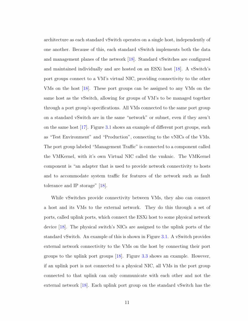
architecture as each standard vSwitch operates on a single host, independently of
one another. Because of this, each standard vSwitch implements both the data
and management planes of the network [18]. Standard vSwitches are configured
and maintained individually and are hosted on an ESXi host [18]. A vSwitch’s
port groups connect to a VM’s virtual NIC, providing connectivity to the other
VMs on the host [18]. These port groups can be assigned to any VMs on the
same host as the vSwitch, allowing for groups of VM’s to be managed together
through a port group’s specifications. All VMs connected to the same port group
on a standard vSwitch are in the same “network” or subnet, even if they aren’t
on the same host [17]. Figure 3.1 shows an example of different port groups, such
as “Test Environment” and “Production”, connecting to the vNICs of the VMs.
The port group labeled “Management Traffic” is connected to a component called
the VMKernel, with it’s own Virtual NIC called the vmknic. The VMKernel
component is “an adapter that is used to provide network connectivity to hosts
and to accommodate system traffic for features of the network such as fault
tolerance and IP storage” [18].
While vSwitches provide connectivity between VMs, they also can connect
a host and its VMs to the external network. They do this through a set of
ports, called uplink ports, which connect the ESXi host to some physical network
device [18]. The physical switch’s NICs are assigned to the uplink ports of the
standard vSwitch. An example of this is shown in Figure 3.1. A vSwitch provides
external network connectivity to the VMs on the host by connecting their port
groups to the uplink port groups [18]. Figure 3.3 shows an example. However,
if an uplink port is not connected to a physical NIC, all VMs in the port group
connected to that uplink can only communicate with each other and not the
external network [18]. Each uplink port group on the standard vSwitch has the
11
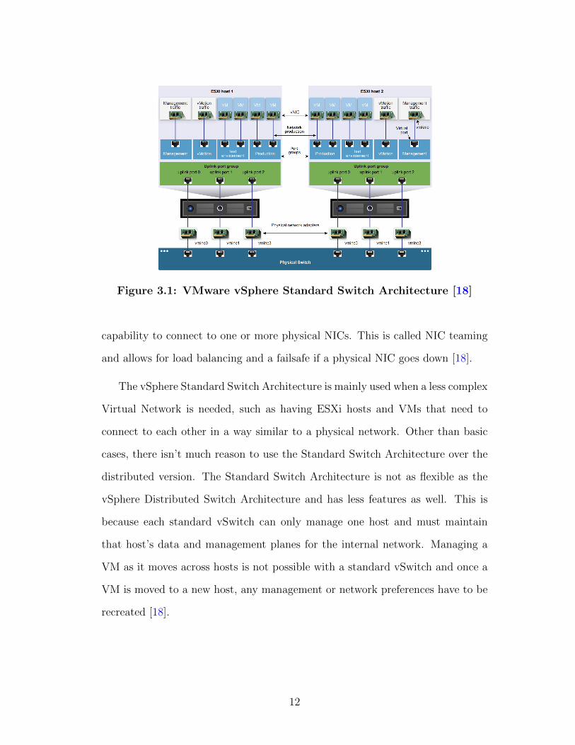
Figure 3.1: VMware vSphere Standard Switch Architecture [18]
capability to connect to one or more physical NICs. This is called NIC teaming
and allows for load balancing and a failsafe if a physical NIC goes down [18].
The vSphere Standard Switch Architecture is mainly used when a less complex
Virtual Network is needed, such as having ESXi hosts and VMs that need to
connect to each other in a way similar to a physical network. Other than basic
cases, there isn’t much reason to use the Standard Switch Architecture over the
distributed version. The Standard Switch Architecture is not as flexible as the
vSphere Distributed Switch Architecture and has less features as well. This is
because each standard vSwitch can only manage one host and must maintain
that host’s data and management planes for the internal network. Managing a
VM as it moves across hosts is not possible with a standard vSwitch and once a
VM is moved to a new host, any management or network preferences have to be
recreated [18].
12
3.1.2 Distributed Switch Architecture
The vSphere Distributed Switch Architecture is more robust than the Stan-
dard Switch Architecture. The Distributed Switch Architecture centralizes the
management plane of the vSwitch so that the vSwitch can be logically connected
to multiple ESXi hosts, allowing for a more flexible Virtual Network to be cre-
ated [18]. In this section we describe the components that differ from the Stan-
dard Switch Architecture and how they work. As with the Standard Switch
Architecture, we then look at the potential use cases and trade-offs.
The Distributed Switch Architecture has more functionality than the standard
switch version due to the distributed nature of the vSwitches. Figure 3.2 shows an
example of the Distributed Switch Architecture. There are many differences be-
tween the standard and distributed vSwitches. Because the distributed vSwitch is
divided among potentially multiple hosts, it allows for the separation of the data
and management plane, unlike in the Standard Switch Architecture [18]. The
data plane acts much like the data plane of a physical network and is responsible
for package switching, filtering, tagging packets, etc. In the Distributed Switch
Architecture, the data plane is still controlled at the host level, same as the Stan-
dard Switch Architecture. The data plane component of a host in the Distributed
Switch Architecture is called the “host proxy switch” and is the part of each host
that receives the network configurations from the management plane [18]. The
management plane is responsible for configuring the data plane, i.e. the virtual
switches and the hosts where the data plane resides [18]. However, in the Dis-
tributed Switch Architecture, the management plane is now controlled by a new
component called vCenter, a virtual server. The configurations for a distributed
vSwitch are made in vCenter and then are stored locally in all the hosts that are
13

Figure 3.2: VMware vSphere Distributed Switch Architecture [18]
“connected” to the distributed vSwitch [18]. “By putting the management plane
in a vCenter server, functionality of the network can be controlled at the highest
level” [18]. This is especially useful in data centers, where the configuration of
all the switches throughout the network can be controlled in one location [18].
The distributed vSwitch has a few differences in the data plane compared to
the standard vSwitch. Like the Standard Switch Architecture, the Distributed
Switch Architecture contains uplink ports on the hosts that connect to the NICs
of the physical switch. The difference between the uplink ports for each vSwitch
is that with the separation of the management and data planes, network config-
urations can now be made for each uplink port group [18]. These configurations
then propagate down to all the host proxy switches that contain the uplink port
group being configured. Another difference in the data plane level is the addition
of the distributed port group. The distributed port group is similar to the port
group used in the standard vSwitches to connect the vSwitch to the VMs on
14
the host [18]. As with the standard vSwitches, the distributed port groups are
identified with labels such as “Production Network”. The difference between a
standard port group and a distributed port group is the latter can be connected
to VMs on multiple hosts and configured from vCenter to have different network
settings. This allows certain VMs, even if they are on different hosts, to share
network settings by being connected to the same distributed port group [18].
Different policies such as load balancing, security, etc. for a group of VMs can be
sent to the host proxy switch and applied differently depending on the distributed
port groups [18].
We have discussed the different distributed vSwitch components, but not
yet how they interact. Figure 3.3 shows a very helpful example of how the
components of an example distributed switch system are connected. The VMs
and VMKernels on each host are each connected to a port in their respective
distributed port group. In this example there is only one port group for the
VMs and one for the VMKernels, but there can be multiple port groups for each.
Also each VM, no matter which physical host it is on, can belong to any of the
distributed port groups. Each distributed port group is connected to one or more
uplink port groups to allow for external network connectivity. In figure 3.3, the
“VM Network” group is connected to two uplink port groups. The distributed
vSwitch allocates an uplink port for each physical NIC on the host. These uplink
ports are then connected to their respective physical NIC. In the figure, each
uplink port group has two ports, one to connect to Host1’s physical NICs and
one to connect to Host2’s physical NICs. If Host1 had another physical NIC, a
4th port for Host1 would be created.
Data flow in the Distributed Switch Architecture is designed to allow for
redundancy, to ensure that VM’s can communicate even when a component is
15
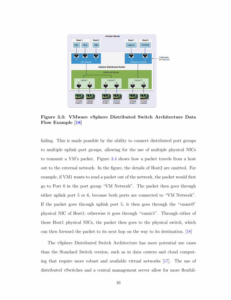
Figure 3.3: VMware vSphere Distributed Switch Architecture DataFlow Example [18]
failing. This is made possible by the ability to connect distributed port groups
to multiple uplink port groups, allowing for the use of multiple physical NICs
to transmit a VM’s packet. Figure 3.4 shows how a packet travels from a host
out to the external network. In the figure, the details of Host2 are omitted. For
example, if VM1 wants to send a packet out of the network, the packet would first
go to Port 0 in the port group “VM Network”. The packet then goes through
either uplink port 5 or 6, because both ports are connected to “VM Network”.
If the packet goes through uplink port 5, it then goes through the “vmnic0”
physical NIC of Host1; otherwise it goes through “vmnic1”. Through either of
those Host1 physical NICs, the packet then goes to the physical switch, which
can then forward the packet to its next hop on the way to its destination. [18]
The vSphere Distributed Switch Architecture has more potential use cases
than the Standard Switch version, such as in data centers and cloud comput-
ing that require more robust and available virtual networks [17]. The use of
distributed vSwitches and a central management server allow for more flexibil-
16
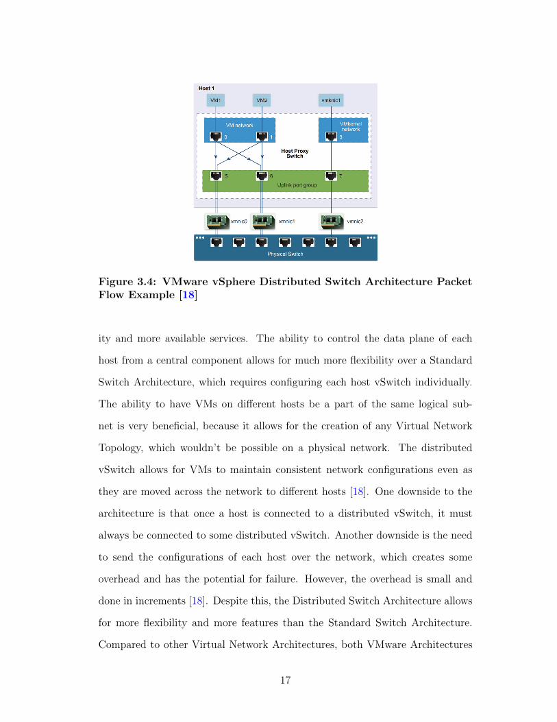
Figure 3.4: VMware vSphere Distributed Switch Architecture PacketFlow Example [18]
ity and more available services. The ability to control the data plane of each
host from a central component allows for much more flexibility over a Standard
Switch Architecture, which requires configuring each host vSwitch individually.
The ability to have VMs on different hosts be a part of the same logical sub-
net is very beneficial, because it allows for the creation of any Virtual Network
Topology, which wouldn’t be possible on a physical network. The distributed
vSwitch allows for VMs to maintain consistent network configurations even as
they are moved across the network to different hosts [18]. One downside to the
architecture is that once a host is connected to a distributed vSwitch, it must
always be connected to some distributed vSwitch. Another downside is the need
to send the configurations of each host over the network, which creates some
overhead and has the potential for failure. However, the overhead is small and
done in increments [18]. Despite this, the Distributed Switch Architecture allows
for more flexibility and more features than the Standard Switch Architecture.
Compared to other Virtual Network Architectures, both VMware Architectures
17

contain more options for use of virtual network, virtual security and distributed
components. Those virtual network and virtual security components are created
and managed by VMware’s NSX. NSX is the system for creating and manag-
ing the distributed vSwitch, more complex virtual networking components and
virtual security components such as virtual firewalls [19]. NSX allows for more
complex network function virtualization. VMware is at an advantage because
they specialize in virtualization, making it easier to integrate more robust virtual
components. However, VMware’s architectures are limited to managing virtual
components of a network and don’t allow for management of physical network
components. This means that other Architectures must be used as well to manage
a full virtual network system.
3.1.3 Palo Alto Networks + VMware Architecture
The Palo Alto Networks (PAN) VM-Series Architecture builds on top of
the VMware vSphere Distributed Switch Architecture to add more security fea-
tures [21]. The PAN VM Series Architecture is different from the other VMware
architectures because of the integration of Palo Alto Networks security compo-
nents. The additions are few enough that the architecture is similar to the Dis-
tributed Switch Architecture talked about above, but the security components
added are important enough that it deserves its own section. We first discuss the
PAN components and then discuss use cases and trade-offs.
VMware has its own virtual network security called NSX, but this architec-
ture allows for the additional use of 3 Palo Alto Networks components: VM-
Series Firewall, Dynamic Address Groups and Panorama Centralized Manage-
ment. “The VM-Series Firewall is a state of the art firewall that has the func-
18
tionality of a hardware firewall but is distributed and virtualized” [21]. The
firewall allows for the testing of unknown malware in a sandbox environment and
many other IDS type features which are absent in the previous VMware archi-
tectures [21]. Dynamic Address Groups allow for the tagging of VMs. Because
VMs can be moved from one physical host to another, this allows for security
policies to be applied to VMs even as they travel across the network [21]. The
Panorama Centralized Management is a central management system for the VM-
Series Firewalls that allows for configuring devices, deploying security policies,
and performing analysis across all the virtual firewalls in the network [21].
These three additional Palo Alto Networks components added on to VMware’s
Distributed Switch Architecture creates a new, combined architecture. Some of
the things that could be improved about the Distributed Switch Architecture
are certain security aspects, such as the lack of visibility into intra VM traffic
and slowness [21]. This architecture greatly increases security for any Virtual
Networks created. The potential downside is the system will be made slower
due to another centrally managed component and the added overhead of all the
security utilized. However, the system isn’t slowed enough to harm the network
and is outweighed by the benefits of having the extra security added. The use
cases for this architecture are the same as the Distributed Switch Architecture
since network part of the architecture operates in the same way. The difference is
simply the added security, which is beneficial in data centers, cloud computing,
and really any use case.
19
3.2 Juniper’s Contrail Architecture
Juniper Networks is a company that specializes in network solutions, both
physical and software-defined. A software-defined network is a network which
separates the control and data plane. A central controller makes the forwarding
decisions and propagates those decisions to the switches, which become simple
forwarding devices [6]. Juniper’s Virtual Network Architecture is called Con-
trail. “Juniper Network’s Contrail is an open-source software-defined networking
(SDN) solution that automates and orchestrates the creation of highly scalable
virtual networks” [5]. Potential use cases are as a cloud networking platform and
for network function virtualization [5]. Contrail allows for the creation of overlay
virtual networks to allow for a separated distribution of physical and virtual re-
sources [5]. An overlay network is when the physical network is used to provide
connectivity, while the virtual networking components lay on top of the physical
servers routing the data [5]. In this section we describe Contrail’s components
and how they work, followed by use cases and trade-offs.
Figure 3.5 shows the details of the Juniper Contrail architecture and how
the components are connected. While there are many components in the sys-
tem, the two main Juniper created components of the architecture are the SDN
Controller and its subnodes, and the vRouters. Contrail’s software-defined net-
work controller is used for management, analytics and control mechanisms of the
system [5]. It is logically central but is physically separate, meaning that the
controller is hosted on multiple physical servers, but is viewed by the rest of the
network as one controller when communicating with it. VRouters are similar to
the VMware vSwitch that we described earlier, except the vRouter also provides
routing [5]. The vRouters act as a forwarding plane that lies in the hypervisor of
20
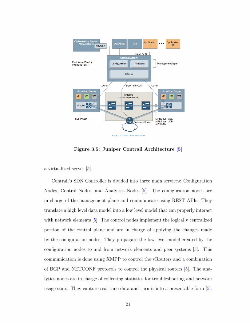
Figure 3.5: Juniper Contrail Architecture [5]
a virtualized server [5].
Contrail’s SDN Controller is divided into three main services: Configuration
Nodes, Control Nodes, and Analytics Nodes [5]. The configuration nodes are
in charge of the management plane and communicate using REST APIs. They
translate a high level data model into a low level model that can properly interact
with network elements [5]. The control nodes implement the logically centralized
portion of the control plane and are in charge of applying the changes made
by the configuration nodes. They propagate the low level model created by the
configuration nodes to and from network elements and peer systems [5]. This
communication is done using XMPP to control the vRouters and a combination
of BGP and NETCONF protocols to control the physical routers [5]. The ana-
lytics nodes are in charge of collecting statistics for troubleshooting and network
usage stats. They capture real time data and turn it into a presentable form [5].
21
Contrail utilizes what is called an overlay virtual network, as described earlier.
The vRouters create tunnels between each other, so when a VM on one physical
host sends a packet to another, it can be routed without interacting with another
overlapping virtual network and without having its data being viewed by any
unauthorized routers/hosts on the way to its destination [5]. VMware’s Virtual
Network Architecture with NSX allows for similar functionality.
Other than the two Juniper components, there is also an orchestration system
for the virtual networking, which can utilize two other Virtual Network Archi-
tectures discussed later, called OpenStack and CloudStack [5]. The orchestration
system is in charge of communicating with the virtualized network functions such
as virtual firewalls and virtual routing components. OpenStack and CloudStack
are Virtual Network Architectures like Contrail, but can be utilized to simply
manage a Virtual Network’s components, which is why they are used in Con-
trail’s Architecture. Contrail also utilizes 3 main interfaces. The first is the
Northbound REST API that is used to talk to apps and the orchestration sys-
tem [5]. The second is the Southbound interfaces used to communicate with the
vRouters and the physical network elements [5]. Lastly, the East-West interface
is utilized for peer to peer communication, such as vRouters communicating with
one another [5].
Juniper’s Architecture utilizes many different forms of communication. The
overlay network’s messaging format is based on MPLS L3VPNs (for layer 3 over-
lay networks) and MPLS EVPNs (for layer 2 overlays) [5]. Contrail’s virtual
overlay network data plane can utilize either MPLS GRE/UDP or VXLAN to
create tunnels of communication between vRouters [5]. The control plane utilizes
BGP for communication [5]. The protocol for communication between the SDN
Controller and the vRouters is very similar to and based off XMPP, and is seman-
22

tically very similar to the BGP protocol [5]. We wont go into detail on how these
protocols work, as knowing how they work isn’t important to understanding the
architecture.
Use cases for Contrail include as a Private Cloud for companies, as an In-
frastructure as a Service, and Virtual Private Cloud for Service Providers and
for managing Network Function Virtualization for Service Provider Networks [5].
Contrail, like other Virtual Network Architectures, is utilized in data centers,
allowing for the creation of multi-tenant virtualized data centers [5]. Contrail
allows each tenant to share physical resources while being assigned their own vir-
tual resources, such as their own virtual networks, virtual storage and VMs [5].
For Network Function Virtualization, Contrail allows for management and or-
chestration of virtualized functions such as firewalls, IDSs, caching, etc. Con-
trail is beneficial as it allows for multiple options in choice of Virtual Network
Orchestrator and type of virtual network components. It also utilizes overlay
networks and tunneling, allowing for logical separation of networks while keep-
ing data protected. However, it doesn’t have as much flexibility as the VMware
Distributed Switch Architecture because its vRouters have similar shortcomings
to the VMware Standard vSwitch, such as only being able to connect to VMs on
one host. Contrail also lacks in security compared to the vSphere Architectures.
While VMware has both NSX and PAN distributed security features that can be
managed from a central location, Contrail’s only allows for the use of external
security components. While other security features such as IDS’s and Firewalls
can be useful in the architecture, they cant be distributed or centrally managed
to more easily secure large parts of the Virtual Networks created.
23
3.3 OpenStack’s Neutron Architecture
OpenStack is a company that created a Cloud Management System that con-
trols “large pools of compute, storage, and networking resources throughout a
data center” [14]. The most important part of that system is virtual network
management and virtual components, which allow for the creation of virtual
and overlay networks. OpenStack Neutron has different architectures based on
the needs of the user, such as classic, high availability and provider (overlay)
networks [10]. Architectures also vary based on different components added or
substituted, such as architectures with and without a linux bridge. The primary
use case for Neutron is in data centers, where it is used to create and manage
Virtual Networks similar to the other architectures we have described [14]. In this
section, we look at the Classic Architecture with Open vSwitch, as it is the ”clas-
sic” architecture type for Neutron and shows the base case for OpenStack Virtual
Networking. We then briefly discuss the High Availability with Distributed Vir-
tual Routing Architecture and the Provider Network Architecture to show the
full capabilities of Neutron. We then look at use cases and trade-offs.
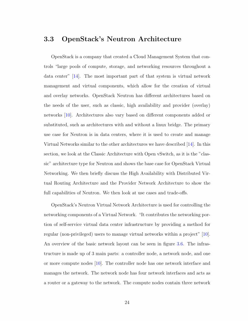
OpenStack’s Neutron Virtual Network Architecture is used for controlling the
networking components of a Virtual Network. “It contributes the networking por-
tion of self-service virtual data center infrastructure by providing a method for
regular (non-privileged) users to manage virtual networks within a project” [10].
An overview of the basic network layout can be seen in figure 3.6. The infras-
tructure is made up of 3 main parts: a controller node, a network node, and one
or more compute nodes [10]. The controller node has one network interface and
manages the network. The network node has four network interfaces and acts as
a router or a gateway to the network. The compute nodes contain three network
24
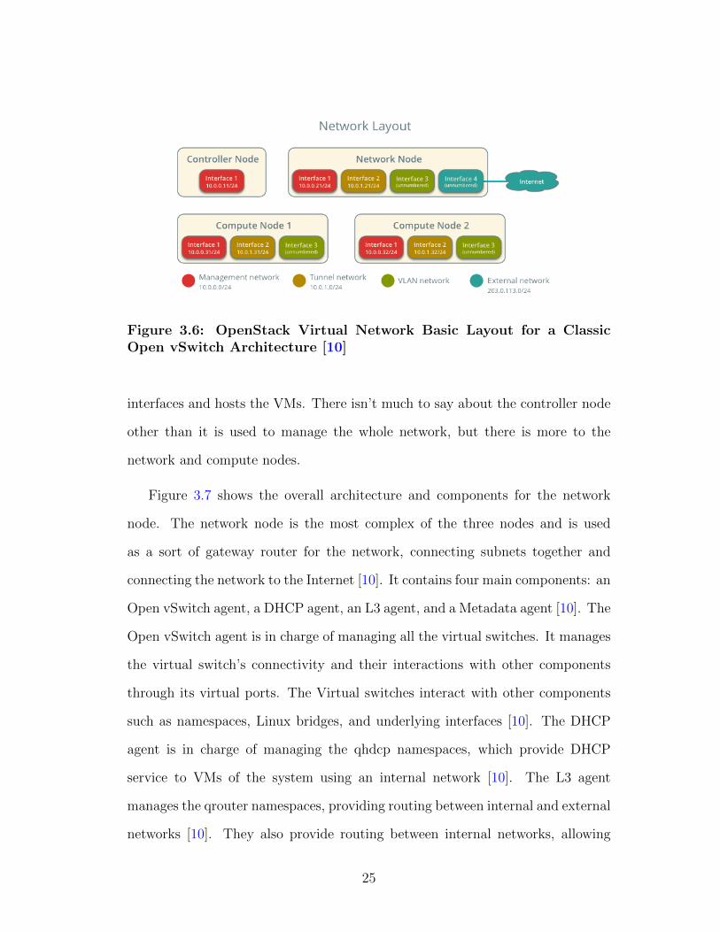
Figure 3.6: OpenStack Virtual Network Basic Layout for a ClassicOpen vSwitch Architecture [10]
interfaces and hosts the VMs. There isn’t much to say about the controller node
other than it is used to manage the whole network, but there is more to the
network and compute nodes.
Figure 3.7 shows the overall architecture and components for the network
node. The network node is the most complex of the three nodes and is used
as a sort of gateway router for the network, connecting subnets together and
connecting the network to the Internet [10]. It contains four main components: an
Open vSwitch agent, a DHCP agent, an L3 agent, and a Metadata agent [10]. The
Open vSwitch agent is in charge of managing all the virtual switches. It manages
the virtual switch’s connectivity and their interactions with other components
through its virtual ports. The Virtual switches interact with other components
such as namespaces, Linux bridges, and underlying interfaces [10]. The DHCP
agent is in charge of managing the qhdcp namespaces, which provide DHCP
service to VMs of the system using an internal network [10]. The L3 agent
manages the qrouter namespaces, providing routing between internal and external
networks [10]. They also provide routing between internal networks, allowing
25
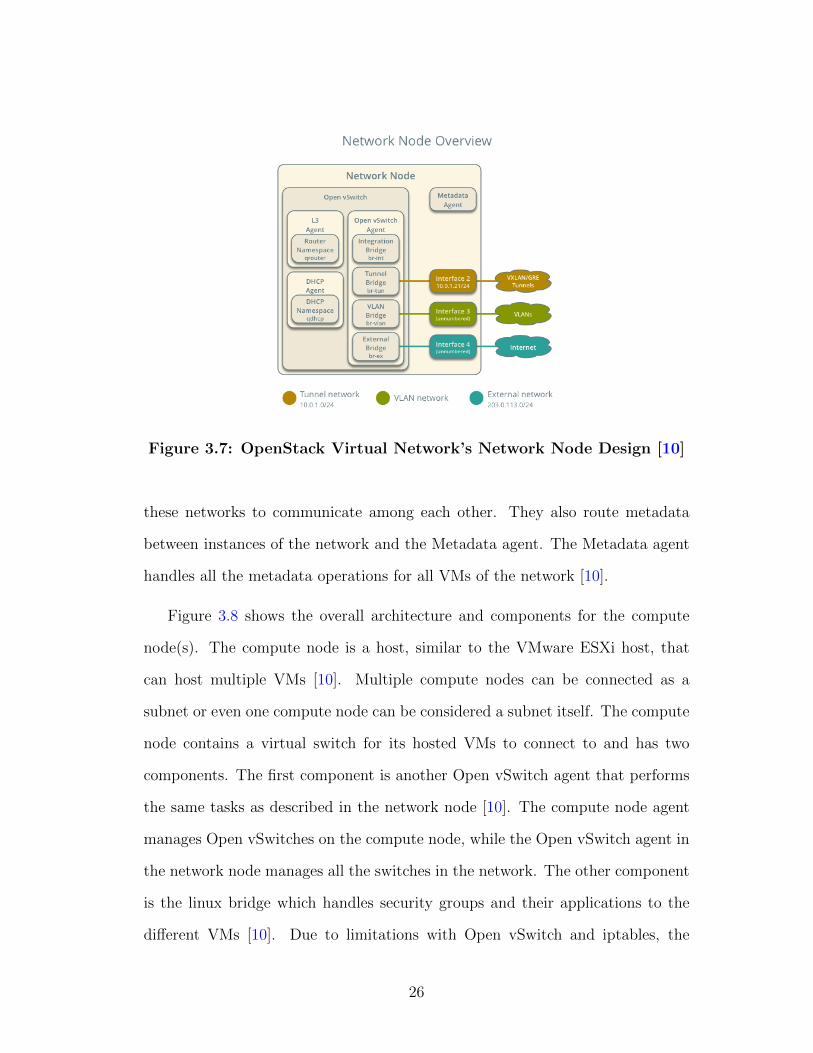
Figure 3.7: OpenStack Virtual Network’s Network Node Design [10]
these networks to communicate among each other. They also route metadata
between instances of the network and the Metadata agent. The Metadata agent
handles all the metadata operations for all VMs of the network [10].
Figure 3.8 shows the overall architecture and components for the compute
node(s). The compute node is a host, similar to the VMware ESXi host, that
can host multiple VMs [10]. Multiple compute nodes can be connected as a
subnet or even one compute node can be considered a subnet itself. The compute
node contains a virtual switch for its hosted VMs to connect to and has two
components. The first component is another Open vSwitch agent that performs
the same tasks as described in the network node [10]. The compute node agent
manages Open vSwitches on the compute node, while the Open vSwitch agent in
the network node manages all the switches in the network. The other component
is the linux bridge which handles security groups and their applications to the
different VMs [10]. Due to limitations with Open vSwitch and iptables, the
26
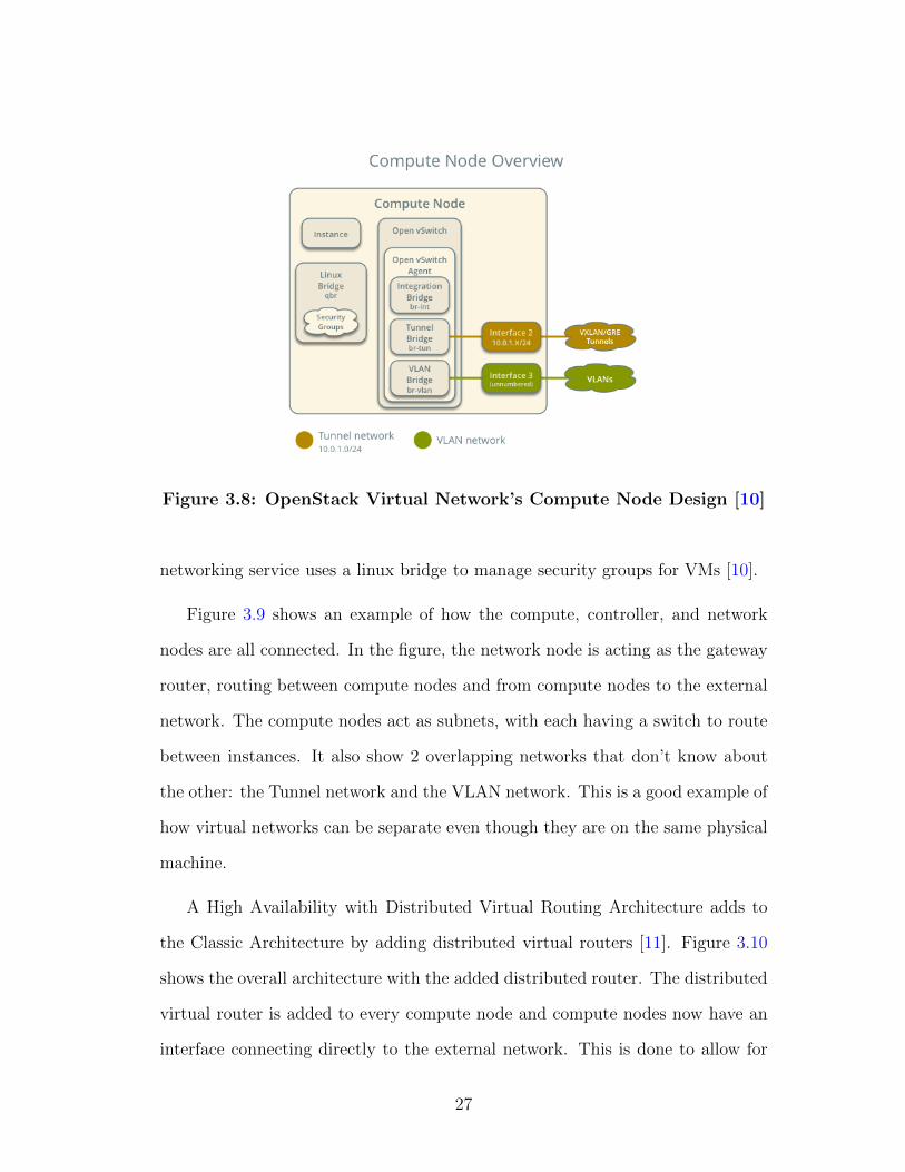
Figure 3.8: OpenStack Virtual Network’s Compute Node Design [10]
networking service uses a linux bridge to manage security groups for VMs [10].
Figure 3.9 shows an example of how the compute, controller, and network
nodes are all connected. In the figure, the network node is acting as the gateway
router, routing between compute nodes and from compute nodes to the external
network. The compute nodes act as subnets, with each having a switch to route
between instances. It also show 2 overlapping networks that don’t know about
the other: the Tunnel network and the VLAN network. This is a good example of
how virtual networks can be separate even though they are on the same physical
machine.
A High Availability with Distributed Virtual Routing Architecture adds to
the Classic Architecture by adding distributed virtual routers [11]. Figure 3.10
shows the overall architecture with the added distributed router. The distributed
virtual router is added to every compute node and compute nodes now have an
interface connecting directly to the external network. This is done to allow for
27
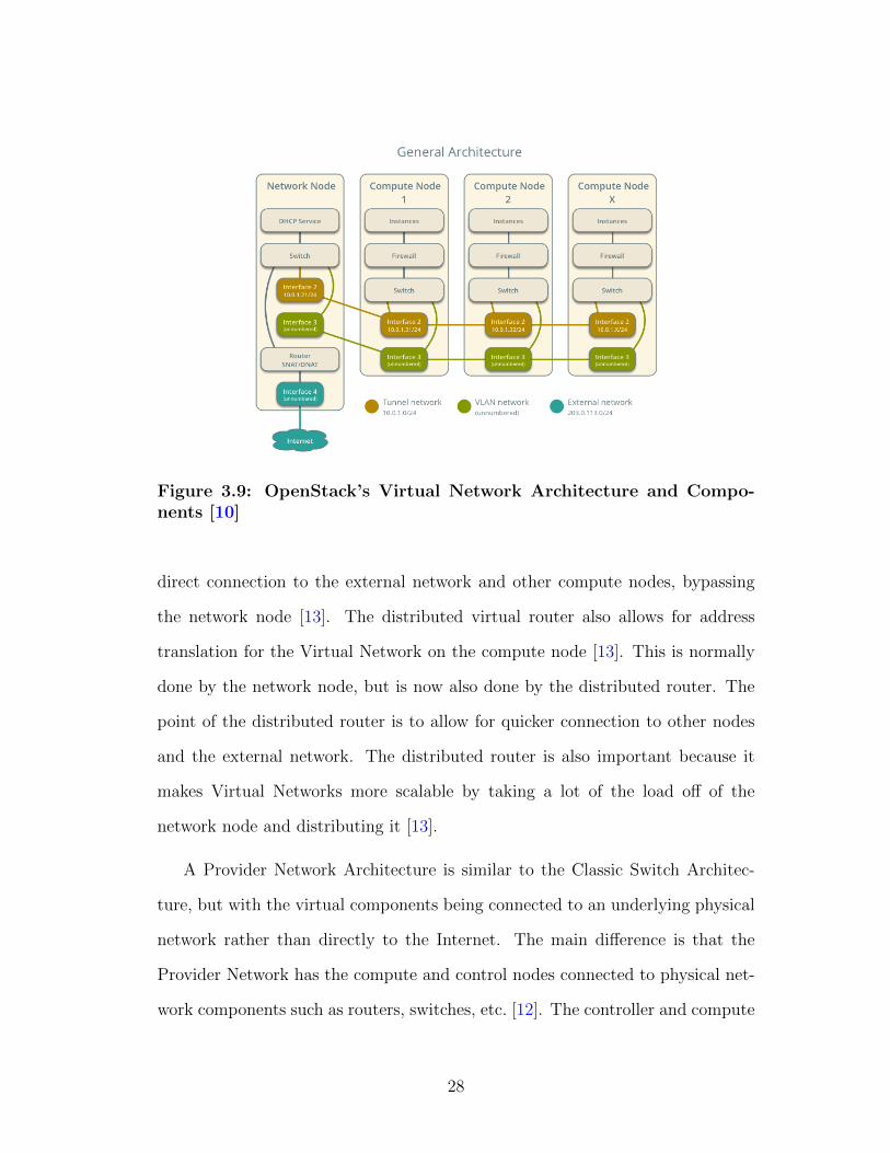
Figure 3.9: OpenStack’s Virtual Network Architecture and Compo-nents [10]
direct connection to the external network and other compute nodes, bypassing
the network node [13]. The distributed virtual router also allows for address
translation for the Virtual Network on the compute node [13]. This is normally
done by the network node, but is now also done by the distributed router. The
point of the distributed router is to allow for quicker connection to other nodes
and the external network. The distributed router is also important because it
makes Virtual Networks more scalable by taking a lot of the load off of the
network node and distributing it [13].
A Provider Network Architecture is similar to the Classic Switch Architec-
ture, but with the virtual components being connected to an underlying physical
network rather than directly to the Internet. The main difference is that the
Provider Network has the compute and control nodes connected to physical net-
work components such as routers, switches, etc. [12]. The controller and compute
28
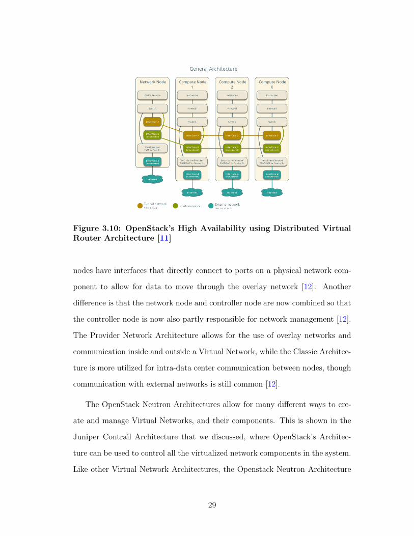
Figure 3.10: OpenStack’s High Availability using Distributed VirtualRouter Architecture [11]
nodes have interfaces that directly connect to ports on a physical network com-
ponent to allow for data to move through the overlay network [12]. Another
difference is that the network node and controller node are now combined so that
the controller node is now also partly responsible for network management [12].
The Provider Network Architecture allows for the use of overlay networks and
communication inside and outside a Virtual Network, while the Classic Architec-
ture is more utilized for intra-data center communication between nodes, though
communication with external networks is still common [12].
The OpenStack Neutron Architectures allow for many different ways to cre-
ate and manage Virtual Networks, and their components. This is shown in the
Juniper Contrail Architecture that we discussed, where OpenStack’s Architec-
ture can be used to control all the virtualized network components in the system.
Like other Virtual Network Architectures, the Openstack Neutron Architecture
29

is mainly used in creating virtual data center networks [12]. Neutron is useful
because it has many architecture types depending on the type of Virtual Network
system that is needed for a solution. The downside is that once one is selected, it
is harder to switch to a different architecture and one can’t reap the benefits of
the different architectures at once. Neutron also has an architecture that utilizes
distributed routers, which allows for more efficient intra-data center communi-
cation [13]. It also makes the system scalable and efficient due to distributing
some of the work done by the network node, such as address translation [13].
Another downside is that similar to Juniper’s Contrail Architecture, there aren’t
as many security features as VMware’s Architectures outside of using normal net-
work IDSs and virtual firewalls. This is seen with OpenStack’s vSwitches having
limitations that force the network node to use a Linux Bridge to manage the
security of VM groups.
3.4 Apache CloudStack Architecture
The Apache Software Foundation is a company that focuses on developing
open-source software. One of their projects is Apache CloudStack. “Apache
CloudStack is an open source cloud computing software, which is used to build
private, public and hybrid Infrastructure as a Service (IaaS) clouds by pooling
computing resources” [7]. Like other architectures, the Apache CloudStack Ar-
chitecture is used in virtualizing datacenter communication. Apache CloudStack,
like OpenStack, has many architectures based on need and is used as an option for
managing network components in the Juniper Contrail Architecture. However,
CloudStack differs from OpenStack in that the different architectures it employs
are based on the size of the desired network and whether certain components
30

such as storage should be separated from the rest of the network. In this section
we first describe the CloudStack Architecture and its components, followed by
use cases and trade-offs.
The Apache CloudStack Architecture allows for the virtualization and man-
agement of data center networks. Figure 3.11 shows an overview of the general
CloudStack Architecture. CloudStack “supports a large set of hypervisors, scal-
able architectures, multi node installation and load balancing, making it a high
availability system” [7]. However, the CloudStack Architecture has fewer compo-
nents and less functionality than the other Architectures we have covered, with
the basic architecture consisting mainly of a management server, storage, and
computing nodes. The management server is what manages the cloud resources
such as provisioning storage, hosts, and ip addresses [7]. Admins can use the
management server through either a user interface or through its API. Storage
has the option of being located on a server within the same part of the network
as the other components or being separated into its own storage subnet [7]. The
computing nodes are the machines hosting the VMs and other virtual network
components [7].
CloudStack has a range of architectures from a very simple, small network to
more complex, more divided networks. The CloudStack Architecture has both
basic networking, similar to an AWS type network, and more advanced network-
ing for more complex network topologies [7]. Figure 3.12 shows the Small-Scale
Deployment Architecture, the most basic CloudStack Architecture [1]. The ar-
chitecture has one subnet with a gateway router/firewall, a layer 2 switch, a
management server, an NFS storage server, and the compute nodes holding the
virtual resources [1]. It also contains a VMware vCenter server if VMware vir-
tual network components are being used [1]. CloudStack has other architectures
31

Figure 3.11: Apache CloudStack’s Virtual Network Architecture andComponents [7]
with more flexible setups, such as architectures that divide certain components
between different subnets.
The CloudStack Architecture allows for various Virtual Network setups rang-
ing from smaller to larger networks. CloudStack is mainly used in data centers
and cloud computing to create and manage Virtual Networks, making intra data
center communication easier. A big benefit of the CloudStack Architecture is
its flexibility in component use. It allows the use of many different VM types,
virtual component types, and even the use of VMware’s vCenter to manage Vir-
tual Network resources (if the Virtual Network components are VMware’s). The
CloudStack Architecture also allows for more functional network setups, which
allow the architecture to handle bigger networks and/or the separation of storage
nodes, which helps lower the load of the management network. However, despite
the increased functionality of some of the Architectures, it still lacks in flexibility
of its implementations. The different architectures of CloudStack are based more
on division of storage than in creating more architectures of varying uses, un-
like OpenStack which allows for plenty of architecture options. The CloudStack
32
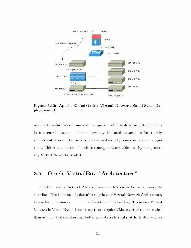
Figure 3.12: Apache CloudStack’s Virtual Network Small-Scale De-ployment [1]
Architecture also lacks in use and management of virtualized security functions
from a central location. It doesn’t have any dedicated management for security
and instead relies on the use of outside virtual security components and manage-
ment. This makes it more difficult to manage network-wide security and protect
any Virtual Networks created.
3.5 Oracle VirtualBox “Architecture”
Of all the Virtual Network Architectures, Oracle’s VirtualBox is the easiest to
describe. This is because it doesn’t really have a Virtual Network Architecture,
hence the quotations surrounding architecture in the heading. To create a Virtual
Network in VirtualBox, it is necessary to use regular VMs as virtual routers rather
than using virtual switches that better emulate a physical switch. It also requires
33
personally creating a management network through VirtualBox’s network setting
and by enabling port forwarding [9]. Other steps to get the network properly
configured are needed as well. So while a Virtual Network can be created in
VirtualBox, it is more of a workaround than a true Virtual Network.
3.6 Comparison
In this section we look at the overarching view of all the architectures and
shortly describe how they compare to each other in certain aspects. Each ar-
chitecture has similar use cases, mainly in data centers and cloud computing,
and each has its own trade-offs. No architecture is necessarily better overall
than any other, but rather each is better in different areas such as flexibility or
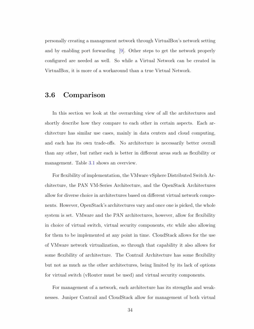
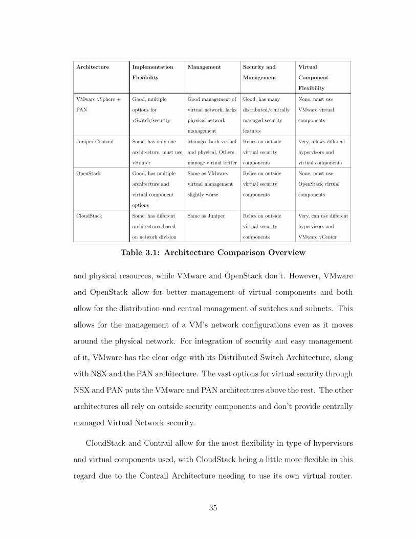
management. Table 3.1 shows an overview.
For flexibility of implementation, the VMware vSphere Distributed Switch Ar-
chitecture, the PAN VM-Series Architecture, and the OpenStack Architectures
allow for diverse choice in architectures based on different virtual network compo-
nents. However, OpenStack’s architectures vary and once one is picked, the whole
system is set. VMware and the PAN architectures, however, allow for flexibility
in choice of virtual switch, virtual security components, etc while also allowing
for them to be implemented at any point in time. CloudStack allows for the use
of VMware network virtualization, so through that capability it also allows for
some flexibility of architecture. The Contrail Architecture has some flexibility
but not as much as the other architectures, being limited by its lack of options
for virtual switch (vRouter must be used) and virtual security components.
For management of a network, each architecture has its strengths and weak-
nesses. Juniper Contrail and CloudStack allow for management of both virtual
34
Architecture Implementation
Flexibility
Management Security and
Management
Virtual
Component
Flexibility
VMware vSphere +
PAN
Good, multiple
options for
vSwitch/security
Good management of
virtual network, lacks
physical network
management
Good, has many
distributed/centrally
managed security
features
None, must use
VMware virtual
components
Juniper Contrail Some, has only one
architecture, must use
vRouter
Manages both virtual
and physical, Others
manage virtual better
Relies on outside
virtual security
components
Very, allows different
hypervisors and
virtual components
OpenStack Good, has multiple
architecture and
virtual component
options
Same as VMware,
virtual management
slightly worse
Relies on outside
virtual security
components
None, must use
OpenStack virtual
components
CloudStack Some, has different
architectures based
on network division
Same as Juniper Relies on outside
virtual security
components
Very, can use different
hypervisors and
VMware vCenter
Table 3.1: Architecture Comparison Overview
and physical resources, while VMware and OpenStack don’t. However, VMware
and OpenStack allow for better management of virtual components and both
allow for the distribution and central management of switches and subnets. This
allows for the management of a VM’s network configurations even as it moves
around the physical network. For integration of security and easy management
of it, VMware has the clear edge with its Distributed Switch Architecture, along
with NSX and the PAN architecture. The vast options for virtual security through
NSX and PAN puts the VMware and PAN architectures above the rest. The other
architectures all rely on outside security components and don’t provide centrally
managed Virtual Network security.
CloudStack and Contrail allow for the most flexibility in type of hypervisors
and virtual components used, with CloudStack being a little more flexible in this
regard due to the Contrail Architecture needing to use its own virtual router.
35
CloudStack is also flexible in that it allows for the use of VMware’s vCenter to
manage the VMware virtual components. Juniper also allows for the choice be-
tween CloudStack and OpenStack for managing virtual resources. VMware/PAN
and OpenStack are not flexible in this category as they require use of their own
virtual components.
36

Chapter 4
Conclusion
In this paper we looked at different Virtual Network Architectures, how they
work, how they are used, and what their strengths and weaknesses are. There
are the VMware Virtual Network Architectures: the Standard Switch Architec-
ture, the Distributed Switch Architecture, and the PAN VM-Series Achitecture.
These architectures allow for the creation and management of flexible and very
secure Virtual Networks, but don’t allow for management of physical network de-
vices. There is the Juniper Contrail Architecture, which allows for management
of whole datacenters, both virtual and physical network components, but doesn’t
have the same robustness of Virtual Networks due to a lack of distribution. It
also doesn’t have centralized, high level virtual security management. There are
the OpenStack Architectures, which allow for various architectures according to
need and allow for both overlay and non-overlay virtual networks. However, they
lack in integration of the positives of their architectures into a single system and
also lack centralized virtual network security management. There is the Apache
CloudStack Architecture which allows for flexibility of setup and virtual compo-
nent type and for management of both physical and virtual network components.
37
However, outside of using vCenter, it doesn’t have distributed virtual compo-
nents, and doesn’t have management and use of virtual security components.
Finally, there is VirtualBox, which doesn’t allow for any virtual network use
outside of setting up VMs to mimic virtual network components. All the archi-
tectures, outside of VirtualBox, are utilized in a variety of datacenter and cloud
computing virtual networking solutions. They all have their benefits and draw-
backs, but all the architectures can be utilized in the creation and management
of Virtual Networks.
38

Chapter 5
Glossary
1. Virtualization The simulation of hardware function in software to allow
for the creation of a virtual computer system [20]
2. Hypervisor
A hypervisor is the VM OS that communicates with the OS of the under-
lying physical machine
3. Software-Defined Netowrk
A software-defined network is a network which separates the control and
data plane. A central controller makes the forwarding decisions and prop-
agates those decisions to the switches, which become simple forwarding
devices [6].
4. Virtual Network
“A network of virtual machines running on a physical machine that are
connected logically to each other so that they can send data to and receive
data from each other” [18]. Many of the physical components of a net-
39
work are turned into purely software version such as virtual routers, virtual
switches, virtual NICs, etc.
5. Virtual Switch
Virtual Switches are similar to physical switches but instead exist purely in
software on top of another physical device. This allows for multiple virtual
switches to exist on the same physical hardware [18].
6. VMware Standard vSwitch
Acts like a physical ethernet switch (without the advanced functionality)
but is purely software and lies on top of physical device. “It detects which
virtual machines are logically connected to each of its virtual ports and uses
that information to forward traffic to the correct virtual machines” [18]. It
can also connect virtual networks to physical networks [18].
7. VMware Distributed vSwitch
It is similar to the standard vSwitch but is distributed across hosts. “It
acts as a single switch across all associated hosts in a data center to pro-
vide centralized provisioning, administration, and monitoring of virtual net-
works” [18]. Allows VM’s to have consistent settings even as they are moved
across hosts [18].
8. Juniper vRouter
VRouters are similar to the VMware vSwitch, with the vRouter providing
some extra higher layer network services. The vRouters act as a forwarding
plane that lies in the hypervisor of a virtualized server [5].
9. VMkernel
40

The VMKernel component is “an adapter that is used to provide network
connectivity to hosts and to accommodate system traffic for features of the
network such as fault tolerance and IP storage” [18].
10. Data Plane
The data plane is responsible for package switching, filtering, tagging pack-
ets, etc. The management plane is responsible for configuring the data
plane, i.e. the virtual switches and hosts that control the data plane.
11. Management Plane
The management plane is responsible for configuring the data plane, i.e.
the virtual switches and hosts that control the data plane.
12. ESXi Host
13. Virtual NIC
Virtual NICs are a purely software NIC for VMs. Virtual NICs act like a
physical NIC and are viewed as a physical NIC to the outside world [18].
Each vNIC has its own MAC address, ip addresses, and responds to ethernet
protocols as if it were a physical NIC [18].
14. Overlay Network
An overlay network is when the physical network is mainly used to pro-
vide connectivity, while the virtual network components lay on top of the
physical servers handle the routing the data [5].
41
Bibliography
[1] Apache. Choosing a deployment architecture.
[2] B. Han, V. Gopalakrishnan, L. Ji, and S. Lee. Network function virtualiza-
tion: Challenges and opportunities for innovations. IEEE Communications
Magazine, 53(2):90–97, Feb 2015.
[3] K. Joshi and T. Benson. Network function virtualization. IEEE Internet
Computing, 20(6):7–9, Nov.-Dec. 2016.
[4] Juniper. Understanding network virtualization with vmware nsx, Nov 2014.
[5] Juniper. Contrail architecture, Sep 2015.
[6] D. Kreutz, F. M. Ramos, and P. Verissimo. Towards secure and depend-
able software-defined networks. In Proceedings of the Second ACM SIG-
COMM Workshop on Hot Topics in Software Defined Networking, HotSDN
’13, pages 55–60, New York, NY, USA, 2013. ACM.
[7] R. Kumar, K. Jain, H. Maharwal, N. Jain, and A. Dadhich. Apache cloud-
stack: Open source infrastructure as a service cloud computing platform.
International Journal of Advancement in Engineering Technology, Manage-
ment and Applied Science, 1(2):111?116, Jul 2014.
42
[8] Y. Li and M. Chen. Software-defined network function virtualization: A
survey. IEEE Access, 3:2542–2553, 2015.
[9] B. Linkletter. How to emulate a network using virtualbox, Oct 2017.
[10] OpenStack. Scenario: Classic with open vswitch, Nov 2016.
[11] OpenStack. Scenario: High availability using distributed virtual routing
(dvr), Nov 2016.
[12] OpenStack. Scenario: Provider networks with open vswitch, Nov 2016.
[13] OpenStack. Neutron ovs dvr - distributed virtual router, Oct 2018.
[14] OpenStack. Openstack docs: Rocky, Aug 2018.
[15] SDNCentral. What is a virtual network?
[16] VMware. Virtualization overview white paper.
[17] VMware. Vmware infrastructure architecture overview.
[18] VMware. vsphere networking.
[19] VMware. Nsx administration guide, Nov 2017.
[20] VMware. Virtualization technology and virtual machine software: What is
virtualization?, Nov 2018.
[21] Vmware and P. A. Networks. Next generation security with vmware nsx and
palo alto networks vm-series, 2014.
43