a survey of data center network · pdf file1 a survey of data center network architectures...
TRANSCRIPT

1
A Survey of Data Center Network ArchitecturesYang Liu, Jogesh K. Muppala, Senior Member, IEEE, Malathi Veeraraghavan, Senior Member, IEEE
Abstract—Large-scale data centers form the core infrastruc-ture support for the ever expanding cloud based services. Thusthe performance and dependability characteristics of data centerswill have significant impact on the scalability of these services. Inparticular, the data center network needs to be agile and reconfig-urable in order to respond quickly to ever changing applicationdemands and service requirements. Significant research workhas been done on designing the data center network topologiesin order to improve the performance of data centers.
In this paper, we present a survey of data center networkdesigns and topologies that have published recently. We startwith a discussion on various representative data center networktopologies, and compare them with respect to several proper-ties in order to highlight their advantages and disadvantages.Thereafter, we discuss several routing protocols designed forthese topologies, and compare them based on various criteria:the basic algorithms to establish connections, the techniquesused to gain better performance and the mechanisms for fault-tolerance. A good understanding of the state-of-the-art in datacenter networks would enable the design of future architectures inorder to improve performance and dependability of data centers.
Index Terms—Data Center Network, Topology, Fault Tolerance
I. INTRODUCTION
DATA center infrastructure design has recently been re-ceiving significant research interest both from academia
and industry, in no small part due to the growing importance ofdata centers in supporting and sustaining the rapidly growingInternet-based applications including search (e.g., Google,Bing), video content hosting and distribution (e.g., YouTube,NetFlix), social networking (e.g., Facebook, Twitter), andlarge-scale computations (e.g., data mining, bioinformatics,indexing). For example, the Microsoft Live online services aresupported by a Chicago-based data center, which is one of thelargest data centers ever built, spanning more than 700,000square feet. In particular, cloud computing is characterizedas the culmination of the integration of computing and datainfrastructures to provide a scalable, agile and cost-effectiveapproach to support the ever-growing critical IT needs (interms of computation, storage, and applications) of both en-terprises and the general public [1] [2].
Manuscript received April XX, XXXX; revised January XX, XXXX.The work described in this paper has been supported by HK RGC under
RGC-Competitive Earmarked Research Grant HKUST 617907Yang Liu is with the Dept. of Computer Science and Engineering, The Hong
Kong University of Science and Technology, Clear Water Bay, Kowloon, HongKong (e-mail: [email protected]).
Jogesh K. Muppala is with the Dept. of Computer Science and Engineering,The Hong Kong University of Science and Technology, Clear Water Bay,Kowloon, Hong Kong (corresponding author phone: +852 2358 6978; fax:+852 2358 1477; e-mail: [email protected]).
Malathi Veeraraghavan is with the Charles L. Brown Department ofElectrical and Computer Engineering, University of Virginia, Charlottesville,VA 22904, USA.
Massive data centers providing storage form the core of theinfrastructure for the cloud [2]. It is thus imperative that thedata center infrastructure, including the data center networkingis well designed so that both the deployment and maintenanceof the infrastructure is cost-effective. With data availability andsecurity at stake, the role of the data center is more criticalthan ever.
The topology of the network interconnecting the servershas a significant impact on the agility and reconfigurabilityof the data center infrastructure to respond to changing appli-cation demands and service requirements. Today, data centernetworks primarily use top of rack (ToR) switches that areinterconnected through end of rack (EoR) switches, whichare in turn connected via core switches. This approach leadsto significant bandwidth oversubscription on the links in thenetwork core [3], and prompted several researchers to suggestalternate approaches for scalable cost-effective network archi-tectures. According to the reconfigurability of the topologyafter the deployment of the DCN, there are fixed architecturesand flexible architectures. Fixed architectures can be furtherclassified into to categories: the tree-based architectures suchas fat tree [3] and Clos Network [4], and recursive topologiessuch as DCell [5], BCube [6]. Flexible architectures such ascThrough[7], Helios [8] and OSA [9] enables reconfigurabilityof their network topology. Every approach is characterizedby its unique network architecture, routing algorithms, fault-tolerance and fault recovery approaches.
Our primary focus in this paper is on data center networktopologies that have been proposed in research literature. Westart with a discussion on various representative data centerarchitectures, and compare them on several dimensions tohighlight the advantages and disadvantages of the topologyused by each architecture. Thereafter, we discuss the routingprotocols designed for these topologies, and compare thembased on various criteria, such as the algorithms used to gainbetter performance and the mechanisms for fault-tolerance.Our goal is to bring out the salient features of the differentapproaches such that these could be used as guidelines inconstructing future architectures and routing techniques fordata center networks. The focus of this survey is data centernetwork topologies and related techniques. We notice thatother researchers have done thorough surveys on other impor-tant issues about data center network, such as routing in datacenters[10], and data center virtualization[11]. Kachris et al.did a survey focusing on optical interconnects for data centersin [12], which also mentioned some of the topologies that willbe discussed in this paper. Wu et al. made comparisons of someexisting DCN architectures in [13]. All the above surveys offera rich set of work that has been done in the area, which helpsto build up this paper.
This paper is organized as follows. First, we briefly review

2
data centers and data center networks in Section II. Thereafter,we discuss the details of data center network topologiesthat are implemented using standard Ethernet switches inSection III. We review the different routing protocols inSection IV. We present a review of techniques to improveperformance in Section VII. We then review fault-tolerantrouting techniques implemented in different architectures todeal with link and switch failures in Section VIII. Finally weconclude the paper in Section IX.
Each of these sections is related to one or more layers ofthe OSI model [14]. We use a table I to show this relationship.
II. BACKGROUND AND MOTIVATION
Two major network fabrics have been considered for imple-menting data center networks: Ethernet and InfiniBand (IBA)[15]. Other high-speed network fabrics such as Myrinet [16]may also be considered. In this survey, we primarily focus ondata center networks that are based on Ethernet technologies.As such, InfiniBand and Myrinet is outside the scope of thissurvey. Interested readers may find more information aboutthese technologies and their use in data centres in [15].
This section motivates the recent research interest in datacenter networking. It first explores the reason why off-the-shelf switching/routing technologies based on Ethernet and IPthat are so widely used in campus, regional and wide-areanetworks are deemed insufficient for data center networks.Next, it lists a set of problems that form the focus of recentresearch proposals for data center networks.
Ethernet is commonly used in data center networks. Thenodes can be configured to operate in Ethernet-switched modeor IP-routed mode. Pros and cons of these two modes ofoperation are discussed below. Scalability is especially aconcern since data center networks increasingly connect 100K- 1 million servers.
The Ethernet 6-byte MAC addressing is flat, i.e., an in-terface can be assigned any address (typically by the man-ufacturer) without consideration of its topological location(i.e., the switch/router to which it is connected). On theother hand, IP addressing is hierarchical, which means theaddress assigned to an interface depends on its topologicallocation. The advantage of hierarchical addressing is thataddresses can be aggregated for use in forwarding tables,which makes the size of forwarding tables smaller than innetworks with flat addressing. This makes IP-routed networksmore scalable than Ethernet-switched networks, which is whythe Internet in which multiple networks, each owned andoperated by a different organization, uses IP routing. However,the disadvantage of hierarchical routing is that if a virtualmachine (VM) is migrated to a different host, one of threeapproaches is required: (i) its IP address needs to changeto reflect its new topological position, which means loss oflive TCP connections as TCP, unlike SCTP [17], does notsupport dynamic address configuration, (ii) forwarding tablesin all intermediate routers are updated with the /32 IPv4 (and/128 IPv6) address of the migrating machine (an inherentlyunscalable solution), or (iii) a solution such as mobile IP[18] is required with home agents registering foreign care-of addresses for the migrating machine and tunneling packets
to the migrating machine at its new location. In contrast, in anEthernet-switched network, the migrating machine can retainits IP address; what needs to change is the IP address to MACaddress resolution stored at the senders. One solution to thisproblem noted in an IBM VM migration document [19] isas follows: “Once traffic from the Virtual Machine on thenew node is sent again the ARP tables will get updated andcommunication will continue as expected.”
Networks with flat addressing, e.g., Ethernet-switched net-works, require no address configuration. Server interfacescome ready for plug-n-play deployment with manufacturer-configured addresses. With any hierarchical addressingscheme, address configuration is required since addresses haveto be assigned to server interfaces based on their topologicallocations. While this step can be automated, it is still a sourceof potential misconfiguration errors.
On the other hand, routing protocols, used to disseminatereachability information, are less feasible in networks withflat addressing. Thus, for example, Ethernet-switched networkshave no explicit routing protocols to spread reachability infor-mation about the flat addresses of servers. Instead floodingand address learning are the methods used to slowly createforwarding table entries. Flooding brings in the specter ofrouting loops, and hence the need for the spanning tree proto-col. Spanning tree protocol avoids loops by disabling certainlinks, but this is wasteful of network bandwidth resources. Toimprove latency and increase throughput, IP routing protocolssuch as OSPF are often augmented with Equal Cost MultiPath(ECMP) techniques [20] in which packet headers are hashedbefore one of multiple paths is selected to avoid out-of-sequence packets within individual flows. Therefore, IP-routednetworks have the distinct advantage of more efficient routingwhen compared to Ethernet-switched networks. The solutionof using Virtual LANs with multiple spanning trees has beenstandardized in IEEE 802.1Q [21] to address some of theseissues. Drawbacks of this VLAN approach as noted by Kim etal. [22] include configuration overhead, limited control-planescalability, and insufficient data-plane efficiency.
Given the above considerations, it appears that neither acompletely flat addressing network (e.g., Ethernet-switchednetwork) nor a completely hierarchical addressing network(e.g., IP-routed network) appears suitable for a highly scalable,agile network that supports host mobility. Interestingly, thesefeatures are required in both data center networks and in thewide-area Internet. Solutions, which are hybrid approachescombining both flat and hierarchical addressing schemes, pro-posed for both arenas are remarkably similar. In the wide-area,Locator-Identifier Split Protocol (LISP) [23] is a representativesolution of using hierarchical addresses as locators in the core,with identifiers being flat addresses in the edges. Equivalentapproaches in the data center network arena are IETF’s TRans-parent Interconnection of Lots of Links (TRILL) [24] and theProvider Backbone Bridging approach in IEEE’s Shortest PathBridging solution [21]. Tunneling is used with the originalpackets encapsulated in new packets whose outer headers carrythe addresses used for packet forwarding through the core(e.g., IP-in-IP, TRILL or MAC-in-MAC). One can visualizethis solution as a network-in-network, with the address space

3
TABLE ILAYERS AND SECTIONS
Section No. Topic LayersPhysical Data Link Network Transport Application
III Architectures X XIV Routing Techniques X XV Traffic Engineering X
VII Performance Enhancement XVIII Fault-tolerant Routing X X X
used in the inner core network being different from that used inthe outer network. Since both the core and the outer networksare connectionless packet-switched networks, the network-layer header1 is repeated, one for forwarding within the core,and one for forwarding at the edges. A second set of solutionsextend tunneling all the way to the servers. This approach isproposed in shim6 [25] for wide-area networks, and VL2 [4]for data center networks.
Whether or not these tunneling approaches are sufficient tomeet the requirements of data center networks is not exploredby most research publications. Instead researchers cite fourmain concerns for justifying work on new architectures, start-ing with the above-described issue of scalability: The mainresearch concerns in data center network design include:
• How to maintain scalability so that data centers can meetfuture demands?
• How to achieve maximum throughput while minimizingthe cost?
• How to guarantee data integrity and system availabilitywhen multiple failures occur in the system?
• How to enhance power efficiency so as to reduce op-erational cost and make data centers environmentallyfriendly?
In this paper, we choose to primarily concentrate on arepresentative subset of data center network architectures thathave appeared in the literature. These include, Fixed topologynetworks based on Fat-tree based architectures as describedin Al-Fares et al. [3], PortLand [26] and Hedera [27]; Closnetwork based architecture represented by VL2 [4]; recursivetopologies such as DCell [5] and BCube [6] and Flexiblearchitectures such as cThrough[7], Helios [8] and OSA [9].Other noteworthy architectures that we do not explicitly coverin this survey, but are worth noting include FiConn [28],MDCube [29], and CamCube [30]. The next four sections de-scribe these set of data center network architectures proposedby academic and industrial research laboratories. In most ofthese architectures, the starting point is a specific topology(Section III). By tying the addressing scheme to the topology,a routing protocol is no longer needed. Instead each node canrun a predetermined algorithm to determine the output linkon which to forward a packet based on its destination address(Section IV). Multipath routing and other techniques are oftenincluded to improve performance (Section VII). Also, as theregular structure of the topology will break down when failuresoccur, automated procedures are required to update forwardingtables (Section VIII).
1Ethernet is considered Layer 2, though switching is defined in the OSIprotocol reference model as a network-layer function.
III. DATA CENTER NETWORK TOPOLOGIES
Considering the cost and availability, high-speed Ethernet(1Gbps, 10Gbps) is most commonly used in constructinginternal network of data centers [15]. However, althoughmost data centers use Ethernet switches to interconnect theservers, there are still many different ways to implementthe interconnections, leading to different data center networktopologies. Each of these different topologies is characterizedby different resource requirements, aiming to bring enhance-ments to the performance of data centers. In the followingsections some representative topologies used in data centerswill be discussed. If servers and switches are regarded asvertices, wires as edges, the topology of every data centernetwork can be represented as a graph.
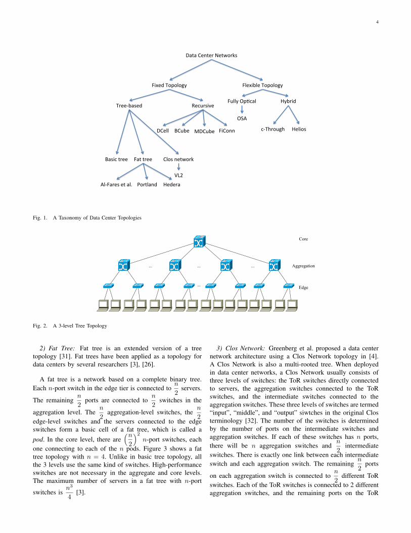
All the topologies discussed in this section can be classifiedinto two categories: fixed and flexible. If the network topologycannot be modified after the network is deployed, we classifyit as a fixed architecture; otherwise it is a flexible architec-ture. Sections III-A and III-B are about topologies for fixedarchitectures, and section III-C is about flexible architectures.Figure 1 gives a taxonomy of the different data center networktopologies.
Furthermore, here we summarise the notations used in thissection:
• n: The number of ports in a switch in an architecture.• k: The number of ports in a server in an architecture.• N : The total number of servers inside a data center
network.It should be noted that n and k may vary according to theposition of the node.
A. Fixed Architectures I: Tree-based Topologies
Standard tree based architectures and their variants arewidely used in designing data center networks [3], [26], [27].
1) Basic Tree: Basic tree topologies consist of either twoor three levels of switches/routers, with the servers as leaves.In a 3-level topology, there is a core tier at the root of the tree,an aggregation tier in the middle, and an edge tier of switchesconnecting to the servers. In a 2-level topology, there is noaggregation tier. There are no links between switches in thesame tier, or in nonadjacent tiers. Figure 2 shows a 3-leveltree topology.
In a basic tree topology, the higher-tier switches need tosupport data communication among a large number of servers.Thus switches with higher performance and reliability arerequired in these tiers. The number of servers in a treearchitecture is limited by the numbers of ports on the switches.
4
Data Center Networks
Fixed Topology Flexible Topology
Tree-‐based Recursive
Basic tree Fat tree Clos network
DCell BCube MDCube FiConn
Hybrid Fully OpAcal
OSA
c-‐Through Helios
Al-‐Fares et al. Portland Hedera
VL2
Fig. 1. A Taxonomy of Data Center Topologies
Core
Aggregation
Edge
... ... ...
...
Fig. 2. A 3-level Tree Topology
2) Fat Tree: Fat tree is an extended version of a treetopology [31]. Fat trees have been applied as a topology fordata centers by several researchers [3], [26].
A fat tree is a network based on a complete binary tree.Each n-port switch in the edge tier is connected to
n
2servers.
The remainingn
2ports are connected to
n
2switches in the
aggregation level. Then
2aggregation-level switches, the
n
2edge-level switches and the servers connected to the edgeswitches form a basic cell of a fat tree, which is called apod. In the core level, there are
(n2
)2n-port switches, each
one connecting to each of the n pods. Figure 3 shows a fattree topology with n = 4. Unlike in basic tree topology, allthe 3 levels use the same kind of switches. High-performanceswitches are not necessary in the aggregate and core levels.The maximum number of servers in a fat tree with n-port
switches isn3
4[3].
3) Clos Network: Greenberg et al. proposed a data centernetwork architecture using a Clos Network topology in [4].A Clos Network is also a multi-rooted tree. When deployedin data center networks, a Clos Network usually consists ofthree levels of switches: the ToR switches directly connectedto servers, the aggregation switches connected to the ToRswitches, and the intermediate switches connected to theaggregation switches. These three levels of switches are termed“input”, “middle”, and “output” siwtches in the original Closterminology [32]. The number of the switches is determinedby the number of ports on the intermediate switches andaggregation switches. If each of these switches has n ports,there will be n aggregation switches and
n
2intermediate
switches. There is exactly one link between each intermediateswitch and each aggregation switch. The remaining
n
2ports
on each aggregation switch is connected ton
2different ToR
switches. Each of the ToR switches is connected to 2 differentaggregation switches, and the remaining ports on the ToR

5
Core
Aggregation
Edge
Pod 0 Pod 1 Pod 2 Pod 3
Fig. 3. A 3-level Fat Tree Topology
Intermediate
Aggregation
Top of Rack
Fig. 4. A Clos Network Topology
switches are connected to servers. There aren2
4ToR switches
because to each pair of aggregation switches,n
2ToR switches
are connected. While intermediate switches and aggregationswitches must have the same number of ports, the number ofports on a ToR switch is not limited. If nToR ports on each
TOR switch are connected to servers, there will ben2
4×nToR
servers in the network. Figure 4 shows a Clos Network withn = 4, nToR = 2.
B. Fixed Architectures II: Recursive Topologies
Tree-based topologies can scale up by inserting more levelsof switches, while each server is connected to only one ofthe bottom level switches. The recursive topologies still havelevels/tiers as in the tree-based topologies. However, recursivetopologies use lower level structures as cells to build higherlevel structures, and the servers in recursive topologies maybe connected to switches of different levels or even otherservers. There are multiple network ports on the servers ofrecursive topologies, making them significantly different fromthe tree-based topologies. Graphs, rather than multi-rootedtrees, are suitable to depict recursive architectures. Somerepresentative recursive topologies will be discussed in thefollowing sections.
1) DCell: DCell [5] is the first type of recursive data centernetwork topology discussed in this paper. The most basicelement of a DCell, which is called DCell0, consists of n
Fig. 5. Constructing a DCell1 from DCell0s with n = 4
servers and one n-port switch. Each server in a DCell0 isconnected to the switch in the same DCell0.
Let DCellk be a level-k DCell. The first step is to construct aDCell1 from several DCell0s. Each DCell1 has n+1 DCell0s,and each server of every DCell0 in a DCell1 is connected to aserver in another DCell0, respectively. As a result, the DCell0sare connected to each other, with exactly one link betweenevery pair of DCell0s. A similar procedure is used to constructa DCellk from several DCellk−1s. In a DCellk, each serverwill eventually have k + 1 links: the first link or the level-0
6
link connected to a switch when forming a DCell0, and level-ilink connected to a server in the same DCelli but a differentDCelli−1. Assume that each DCellk−1 has tk−1 servers, then aDCellk will consist of tk DCellk−1s, and consequently tk−1×tk servers. Obviously, we have tk = tk−1×(tk−1 + 1). Figure5 shows a DCell1 when n = 4. It can be seen that the numberof servers in a DCell grows double-exponentially, and the totalnumber of levels in a DCell is limited by the number of NICson the servers in it. DCell can scale to very large number ofservers using switches and servers with very few ports. Forexample, when n = 6, k = 3, a fully constructed DCell cancomprise more than 3 million servers [5].
2) BCube: BCube [6] is a recursive topology speciallydesigned for shipping container based modular data centers.Building a data center cluster in a 20- or 40-foot shippingcontainer makes it highly portable. As demands change atdifferent data centers, the whole cluster can be readily moved.While the deployment time is considerably shorter, the dis-advantage of this environment is that due to operational andspace constraints, once deployed in the field, it is difficult toservice the cluster.
The most basic element of a BCube, which is named asBCube0, is also the same as a DCell0: n servers connected toone n-port switch. The main difference between BCube andDCell lies in how they scale up. BCube makes use of moreswitches when constructing higher level architecture. Whileconstructing a BCube1, n extra switches are used, connectingto exactly one server in each BCube0. Therefore a BCube1contains n BCube0s and n extra switches(If the switches inthe BCube0s are taken into consideration, there are totally2n switches in a BCube1). More generally, a BCubek isconstructed from n BCubek−1s and nk extra n-port switches.These extra switches are connected to exactly one server ineach BCubek−1. In a level-k BCube, each level requires nk
switches (each of which is an n-port switch).BCube makes use of more switches when constructing
higher level structures, while DCell uses only level-0 n-portswitches. Both however require servers to have k+1 NICs. Theimplication is that servers will be involved in switching morepackets in DCell than in BCube. Figure 6 shows a BCube1with n = 4.
Just like the DCell, the number of levels in a BCube dependson the number of ports on the servers. The number of servers inBCube grows exponentially with the levels, much slower thanDCell. For example, when n = 6, k = 3, a fully constructedBCube can contain 1296 servers. Considering that BCube isdesigned for container based data centers, such scalability issufficient [6].
C. Flexible Architectures
Recently, more and more researchers ([7], [8], [9]) haveconsidered using optical switching technology to constructDCNs. Besides offering high bandwidth (up to Tbps perfiber with WDM techniques), optical networks have significantflexibility of reconfiguring the topology during operation. Suchfeature is important considering the unbalanced and ever-changing traffic patterns in DCNs. In this section, we introduce
electrical opticalelectrical
Mux Mux Mux Mux
Fig. 8. Helios Network
three of the flexible architectures: c-Through [7], Helios [8]and OSA [9].
1) c-Through: c-Through [7] is a hybrid network archi-tecture which makes use of both electrical packet switchingnetwork and optical circuit switching network. The hybridnetwork of c-Through, or the so-called HyPaC (Hybrid Packetand Circuit) Network, consists of two parts: a tree-basedelectrical network which maintains connectivity between eachpair of ToR switches, and a reconfigurable optical networkwhich offers high bandwidth interconnection between certainracks. Due to the relatively high cost optical network and thehigh bandwidth of optical links, it is unnecessary and not cost-effective to maintain an optical link between each pair of racks;instead c-Through connects each rack to exactly one other rackat a time. As a result, the high capacity optical links are offeredto pairs of racks transiently according to the traffic demand.The estimation of traffic between racks and reconfiguration ofthe optical network is accomplished by the control plane of thesystem. Figure 7 shows a c-Through network (servers whichare directly connected to ToR switches are not shown).
To configure the optical part of c-Through network, thetraffic between racks should be known. c-Through estimatesthe rack-to-rack traffic demands by observing the occupancyof socket buffer. Since only one optical link is offered toeach rack, the topology should be configured such that themost amount of estimated traffic can be satisfied. In [7],the problem is solved using the maximum-weight perfectmatching algorithm (Edmonds’ Algorithm) [33]. The topologyof the optical network is configured accordingly.
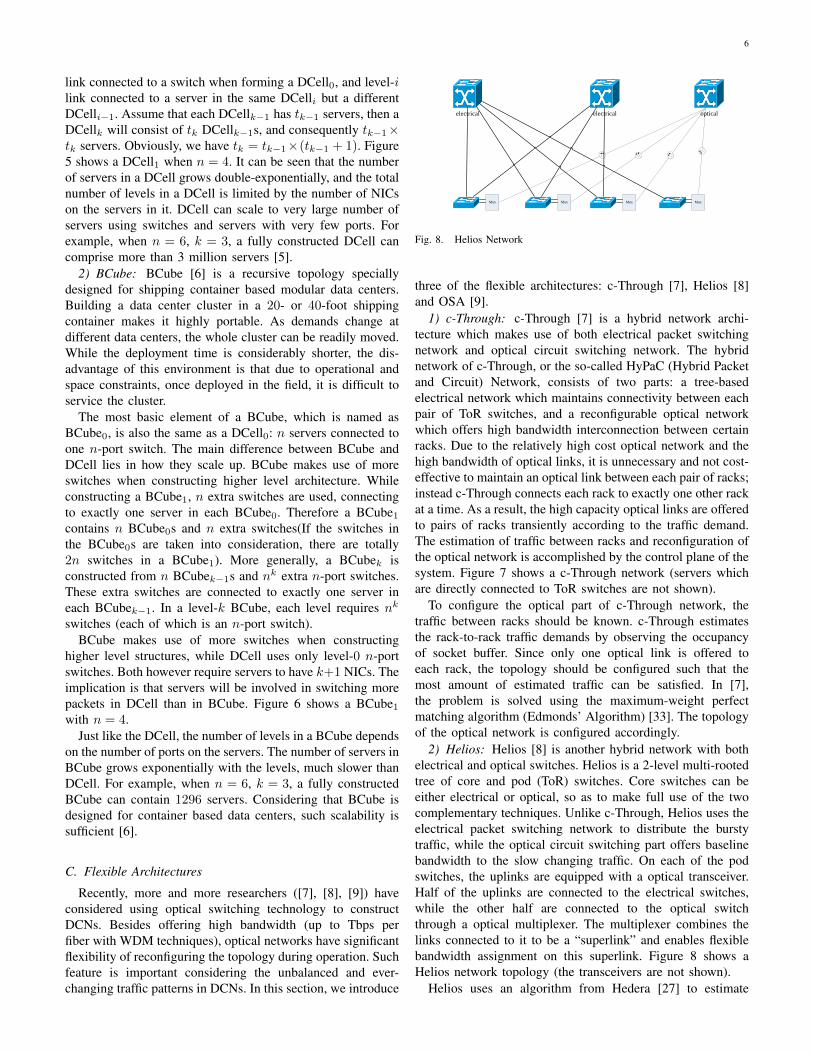
2) Helios: Helios [8] is another hybrid network with bothelectrical and optical switches. Helios is a 2-level multi-rootedtree of core and pod (ToR) switches. Core switches can beeither electrical or optical, so as to make full use of the twocomplementary techniques. Unlike c-Through, Helios uses theelectrical packet switching network to distribute the burstytraffic, while the optical circuit switching part offers baselinebandwidth to the slow changing traffic. On each of the podswitches, the uplinks are equipped with a optical transceiver.Half of the uplinks are connected to the electrical switches,while the other half are connected to the optical switchthrough a optical multiplexer. The multiplexer combines thelinks connected to it to be a “superlink” and enables flexiblebandwidth assignment on this superlink. Figure 8 shows aHelios network topology (the transceivers are not shown).
Helios uses an algorithm from Hedera [27] to estimate

7
Fig. 6. Constructing a BCube1 from BCube0s with n = 4
Core
Aggregation
ToR
... ... ...
...
Optical Switch
Fig. 7. c-Through Network
traffic demand between racks, which allocates fair bandwidthfor TCP flows. The goal of the configuration of optical networkis the same as c-Through: to maximize the traffic demandthat can be satisfied. Helios also formulates the optimizationproblem as maximum-weight matching and solves it usingEdmonds’ Algorithm.
3) OSA: OSA [9] is a “pure” optical switching network,which means that it abandons the electrical core switchesand use only optical switches to construct the switching core.The ToR switches are still electrical, converting electrical andoptical signals between servers and the switching core. OSAallows multiple connections to the switching core on eachToR switch (the typical amount of such links is 4). However,the connection pattern is determined flexibly according tothe traffic demand. Since the network does not ensure directoptical link between each pair of rack with traffic demand,the controlling system constructs the topology to make it aconnected graph, and ToR switches are responsible to relaythe traffic between other ToR switches.
OSA estimates the traffic demand with the same methodas Helios. However in OSA, there can be multiple opticallinks offered to each rack, and the problem can no longer beformulated as the maximum-weight matching problem. It is amulti-commodity flow problem with degree constraints, whichis NP-hard. In [9], the problem is simplified as a maximum-weight b-matching problem [34], and approximately solved byapplying multiple maximum-weight matchings.
D. Comparisons Of Topologies
1) Parameter Comparison: Table II presents a comparisonof some of the parameters of the topologies introduced earlier.The flexible architectures are not shown because they do nothave a fixed topology. The following parameters are used whencomparing the different topologies:
• Degree of the servers: The (average) number of networkports on the servers in the data center. For the tree-based topologies, only one port is needed on each server.However, in the recursive topologies, the number of portsvary according to the levels required. Considering the datashown in table III, k does not need to be large to scale up.On the other hand, since the servers are not specificallydesigned for switching, and the actual bandwidth that aserver can offer is also limited by the speed of storage,it will be meaningless to add more and more ports onservers.
• Diameter: The longest of the shortest paths between twoservers in a data center. A smaller diameter leads tomore effective routing, and lower transmission latencyin practice. For most topologies the diameter growslogarithmically with the number of servers.
• Number of Switches: It is assumed that all switches arethe same in each topology except Clos Network. Thisassumption also stands for tables III, IV and V. BCubeuses the largest amount of switches, which may lead tohigher cost. The basic tree architecture uses the fewestswitches because there is little hardware redundancy inthe architecture.
• Number of Wires: This metric shows the number of wiresrequired when deploying a data center. Similar to the

8
TABLE IISUMMARY OF PARAMETERS
Tree-based Architecture Recursive ArchitectureBasic Tree Fat Tree [3] Clos Network [4] DCell [5] BCube [6]
Degree of Servers 1 1 1 k + 1 k + 1
Diameter 2logn−1N 6 6 2k+1 − 1 logn N
No. of Switches n2+n+1n3 N 5N
n32n+ n2
4Nn
Nn
logn N
No. of Wires nn−1
(N − 1) N logn2
N2
N + 4NnToR
(k2+ 1
)N N logn N
No. of Servers (n− 1)3 n3
4n2
4× nToR
≥(n+ 1
2
)2k − 12,
nk+1
≤ (n+ 1)2k− 1
i Typically k is smaller for DCell because it needs smaller k to connect the same number of servers compared toother recursive architectures.
condition of the number of switches, BCube uses the mostwires, and then DCell. However, it should be noted thatthe number of wires only shows the wiring complexity;it does not show the accurate wiring cost, because not allthe architectures use homogeneous wires. E.g., the typicalbandwidth of a link between an aggregation switch anda core switch in fat-tree is 10 Gbps, while it is 1Gbps ona link between a server and an edge switch.
• Number of Servers: All the metrics above are countedunder the same number of servers (N ), while this oneshows the scalability of different architectures with thesame n and k (for recursive architectures only). It isassumed in this row that the tree-based architectures use3-level structure. Considering the data in table III, it isno doubt that DCell scales up much faster than otherarchitectures for the number of servers in DCell growsdouble-exponentially with k.
2) Performance Comparison: Table IV shows the compar-isons of some performance metrics of different topologies.
• Bandwidth: The first four rows of table IV show the band-width that the topologies can offer under different trafficpatterns. “One-to-one” means the maximum bandwidththat the topology can offer when one arbitrary serversends data to another arbitrary server, and so on so forth.“All-to-all” bandwidth means every server establishes aflow to all the other servers. Each kind of these trafficpattern is meaningful for different applications. E.g., one-to-several traffic occurs when the file system is makingreplicas, one-to-all traffic occurs when updating somesoftware on all the servers, and all-to-all traffic is verycommon in MapReduce.Here in table IV the bandwidths are expressed as thenumber of links, which implies that each link in a datacenter has the same bandwidth. It is shown in the tablethat one-to-one, one-to-several and one-to-all bandwidthsare in fact limited by the number of ports on the servers,or the degree of servers. The basic tree topology offersthe smallest all-to-all bandwidth, limited by the numberof ports of the switch at the root. Since fat tree introducesredundant switches, it can offer as many edge-disjointpaths as the number of servers.
• Bisection Width: The minimum number of wires thatmust be removed when dividing the network into twoequal sets of nodes. The larger it is, the better fault
tolerance ability a topology will have. A similar metric,the bisection bandwidth is also widely used, which meansthe minimum collective bandwidth of all the wires thatmust be removed to divide the network into two equalsets of nodes. Basic tree has the smallest bisection width,which means that it is the most vulnerable of all.
Another important property, the relationship between all-to-all bandwidth and the ratio of faulty components is notshown in the table because of lack of testing data for allthe topologies. A graceful degradation of performance impliesthat when more and more components fail in the data center,performance reduces slowly without dramatic falls. Whenbuilding a new data center, it is usual that a partial topologywill be built first, and more components are added accordingto future need. This partial network can be viewed as anetwork with a lot of failures. Building a partial networkwith a topology of graceful degradation means that people canget expected performance with fewer components. [6] gives acomparison between fat tree, DCell and BCube on this metricwith simulation results.
3) Hardware Redundancy of Data Center Network Topolo-gies: The hardware redundancies discussed here are based onthe topology of data center network. Some data center networkarchitectures, such as PortLand and VL2, which requires morereliability for their centralized management system, are notconsidered here.
Table V shows the hardware redundancy offered by differenttopologies. Before discussing the table, some definitions needto be clarified:
Definition 3.1 (Node-disjoint Paths): The minimum of thetotal number of paths that share no common intermediatenodes between any arbitrary servers.
Definition 3.2 (Edge-disjoint Paths): The minimum of thetotal number of paths that share no common edges betweenany arbitrary servers.
Definition 3.3 (f -fault tolerance): [35] A network is f -fault tolerant if for any f failed components in the network,the network is still connected.
Definition 3.4 (Redundancy Level): [35] A network has aredundancy level equal to r if and only if, after removing anyset of r links, it remains connected, and there exists a set ofr + 1 links such that after removing them, the network is nolonger connected.
In the table, the redundancy levels of different componentsare shown respectively, which reflects the influence of different
9
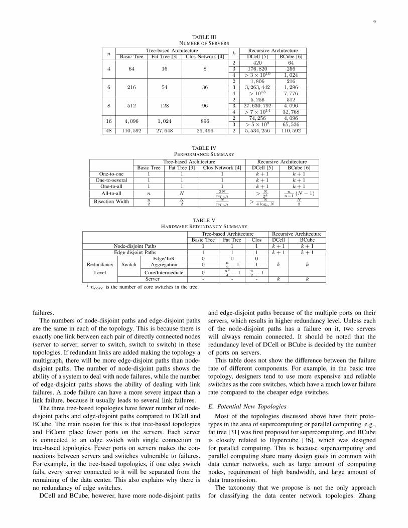
TABLE IIINUMBER OF SERVERS
nTree-based Architecture
kRecursive Architecture
Basic Tree Fat Tree [3] Clos Network [4] DCell [5] BCube [6]
4 64 16 82 420 643 176, 820 2564 > 3× 10¹⁰ 1, 024
6 216 54 362 1, 806 2163 3, 263, 442 1, 2964 > 1013 7, 776
8 512 128 962 5, 256 5123 27, 630, 792 4, 0964 > 7× 10¹⁴ 32, 768
16 4, 096 1, 024 8962 74, 256 4, 0963 > 5× 10⁹ 65, 536
48 110, 592 27, 648 26, 496 2 5, 534, 256 110, 592
TABLE IVPERFORMANCE SUMMARY
Tree-based Architecture Recursive ArchitectureBasic Tree Fat Tree [3] Clos Network [4] DCell [5] BCube [6]
One-to-one 1 1 1 k + 1 k + 1One-to-several 1 1 1 k + 1 k + 1
One-to-all 1 1 1 k + 1 k + 1
All-to-all n N 2NnToR
> N2k
nn−1
(N − 1)
Bisection Width n2
N2
NnToR
> N4 logn N
N2
TABLE VHARDWARE REDUNDANCY SUMMARY
Tree-based Architecture Recursive ArchitectureBasic Tree Fat Tree Clos DCell BCube
Node-disjoint Paths 1 1 1 k + 1 k + 1Edge-disjoint Paths 1 1 1 k + 1 k + 1
SwitchEdge/ToR 0 0 0
k kRedundancy Aggregation 0 n2− 1 1
Level Core/Intermediate 0 n2
4− 1 n
2− 1
Server - - - k ki ncore is the number of core switches in the tree.
failures.The numbers of node-disjoint paths and edge-disjoint paths
are the same in each of the topology. This is because there isexactly one link between each pair of directly connected nodes(server to server, server to switch, switch to switch) in thesetopologies. If redundant links are added making the topology amultigraph, there will be more edge-disjoint paths than node-disjoint paths. The number of node-disjoint paths shows theability of a system to deal with node failures, while the numberof edge-disjoint paths shows the ability of dealing with linkfailures. A node failure can have a more severe impact than alink failure, because it usually leads to several link failures.
The three tree-based topologies have fewer number of node-disjoint paths and edge-disjoint paths compared to DCell andBCube. The main reason for this is that tree-based topologiesand FiConn place fewer ports on the servers. Each serveris connected to an edge switch with single connection intree-based topologies. Fewer ports on servers makes the con-nections between servers and switches vulnerable to failures.For example, in the tree-based topologies, if one edge switchfails, every server connected to it will be separated from theremaining of the data center. This also explains why there isno redundancy of edge switches.
DCell and BCube, however, have more node-disjoint paths
and edge-disjoint paths because of the multiple ports on theirservers, which results in higher redundancy level. Unless eachof the node-disjoint paths has a failure on it, two serverswill always remain connected. It should be noted that theredundancy level of DCell or BCube is decided by the numberof ports on servers.
This table does not show the difference between the failurerate of different components. For example, in the basic treetopology, designers tend to use more expensive and reliableswitches as the core switches, which have a much lower failurerate compared to the cheaper edge switches.
E. Potential New TopologiesMost of the topologies discussed above have their proto-
types in the area of supercomputing or parallel computing. e.g.,fat tree [31] was first proposed for supercomputing, and BCubeis closely related to Hypercube [36], which was designedfor parallel computing. This is because supercomputing andparallel computing share many design goals in common withdata center networks, such as large amount of computingnodes, requirement of high bandwidth, and large amount ofdata transmission.
The taxonomy that we propose is not the only approachfor classifying the data center network topologies. Zhang

10
et al. [38] proposes a taxonomy by classifying data centernetworks into two categories, hierarchical topologies and flattopologies, which correspond to the tree-based topologies andrecursive topologies in our survey respectively. Lucian Popa etal. classify the architectures into switch-only and server-onlytopologies in [39].
IV. ADDRESSING, FORWARDING AND ROUTING IN DATACENTER NETWORK ARCHITECTURES
Given a network topology, routing techniques and protocolsdefine how data packets are delivered from a source to adestination within a data center. The orchestration of thenetwork in order to achieve the goals of data delivery amongthe servers is what we discuss next in this section. Addressesare used to uniquely identify interfaces (or nodes) within a datacenter network. Forwarding is the mechanism by which pack-ets are forwarded from one link to another at switches/routers.Typically this action is based on destination address carried ina packet header. The data-plane protocol used for packet for-warding specifies the addressing format used. Also of interestis the node at which forwarding actions take place. In mostcases, these actions occur at switches/routers, but in severalof the architectures compared here, servers perform packetforwarding between the several NICs with which they areequipped. Such forwarding in servers can be implemented insoftware or special hardware. Finally, the routing mechanismsused to determine the next-hop node, whether executed on apacket-by-packet basis, or used in conjunction with routingprotocols for a pre-configuration of forwarding tables, arepresented for each architecture. The focus of this section ison unicast, single-path routing, while multi-path routing willbe discussed in section VII. Now we present the details of theaddressing, forwarding and routing mechanisms used in thedifferent network architectures described in section III.
A. Fat-Tree Architecture of Al-Fares et al. [3]
At first glance, it appears that this architecture proposes adirect use of IP routers in a fat-tree topology, and specifiesa particular address assignment scheme that leverages theregular topology eliminating the need for a routing protocolsuch as OSPF. In other words, a simple algorithm can beexecuted to determine the output port based on the destinationIP address given that the algorithm leverages the structuredmanner in which addresses are assigned.
However, on closer examination, one sees that the nodesat which packet forwarding occurs cannot be off-the-shelfIP routers performing standard longest-prefix matching opera-tions. Instead a new router design (Al-Fares et al. [3] refer tothe nodes as switches even though packet forwarding action isat the IP layer. The term router is hence more appropriate)is required for a two-level lookup. Therefore, even thoughthe data-plane protocol is unchanged, i.e., servers generateIP datagrams carried in Ethernet frames, new routers needto be designed, implemented, and deployed to realize thisarchitecture.
As for the routing mechanism, a centralized controller isenvisioned to create the two-level forwarding tables at all
the routers in the fat tree so that the forwarding action isreduced to a two-level table lookup rather than execution ofthe algorithm on a packet-by-packet basis. Mention is madeof needing distributed routing protocols to handle failures, butno details are provided.
1) Addressing: Al-Fares et al. [3] make use of the dotteddecimal notation of IP addresses to specify the position of anode(either a server or a switch) in the tree. As describedin III-A2, a fat tree has n pods, with n switches in eachpod, while
n
2servers are connected to each of the
n
2edge
switches in a pod. The reserved private 10.0.0.0/8 blockis allocated to the nodes. The pod switches, including edgeswitches and aggregation switches are addressed in the form10.pod.switch.1, where pod ∈ [0, n− 1] denotes the numberof the pod that a switch belongs to, and switch ∈ [0, n− 1]
denotes the position of a switch in a pod. Then2
4core switches
are addressed as 10.k.j.i, where i, j ∈[1, n
2
].
Then
2servers connected to edge switch 10.pod.switch.1
is addressed as 10.pod.switch.ID, where ID ∈[2, n
2 + 1]
denotes the position of the server in the subnet connected tothe switch. With such an addressing scheme, n can be as largeas 256, supporting as many as 4.19M servers.
2) Forwarding and Routing: In the fat tree architectureshown in section 3, the core switches need to transmit allthe inter-pod traffic. If hop count is used as the metric of
evaluating a route, there will be(n2
)2shortest routes between
two servers in different pods, each route with 6 hops: 3 hopsfrom the source up to a core switch, and 3 hops from thecore switch down to the destination. The main goal of routingin fat-tree is to distribute the traffic evenly among these coreswitches.
Al-Fares et al. [3] propose a 2-level routing table to solvethis problem. Unlike the common routing table in which oneentry relates several IP address with one port on the switch,every entry in this 2-level routing table may potentially have apointer to a small secondary table. The entries of the secondarytable are in the form of (suffix, port), while the entries in theprimary table are like (prefix, port). Not all the entries of theprimary table have a pointer to a secondary entry, while onesecondary entry may be pointed to by multiple primary entries.A primary entry is terminating if it points to no secondaryentry. When routing a packet, the destination IP address willbe first checked to match the longest prefix in the primarytable. If the result primary entry points to a secondary table,the destination IP will be checked again to match the longestsuffix, and the output port will be finally decided.
In such a two-level routing scheme, the pod switcheshave terminating prefixes for the servers in that pod, and adefault /0 prefix with a secondary table for addresses outsidethe pod. As a result, in a pod switch, the entries in theprimary table will distinguish destination servers that do notbelong to the same pod, and the entries in a secondary tabledirects packets to different paths so as to get a balanced flowdistribution, e.g., the aggregation switches will transfer packetswith different suffixes through different core switches so thateach core switch will receive the same number of packets in
11
all-to-all traffic. For the core switches, the routing tables aresimpler. They are assigned terminating prefixes for all networkaddresses, so that they can correctly direct every packet to thepod where the destination server is. Because one core switchhas exactly one link to an aggregation switch in each pod,and one aggregation switch has exactly one link to every edgeswitch in its pod, when a packet arrives at a core switch,the remaining of its shortest path to the destination is unique.Traffic diffusion only happens at the first half of a path, i.e.,before a packet reaches a core switch.
It should be noted that in such a routing scheme, the originalrouting table is generated according to the architecture, not byany autonomous route discovering mechanism.
B. PortLand and Hedera: Layer-2 Routing Fabric for Tree-based Topologies
PortLand [26] offers layer-2 addressing, forwarding androuting in multi-rooted tree based data centers. Hedera [27]is based on PortLand, and its implementation augments Port-Land routing and fault tolerant protocols. Unlike the routingschemes we have discussed, PortLand/Hedera use a centralizedsolution to manage the whole fabric.
1) Addressing in PortLand: PortLand uses a 48-bit hier-archical Pseudo MAC (PMAC) addressing scheme to realizeforwarding, routing and VM migration. A unique PMAC isassigned to each machine (physical or virtual), encoding thelocation of it. For example, in the fat tree architecture, all thecomputers inside the same pod will have the same prefix inthe PMAC addresses. The machine itself, however, remainsunmodified. It still keeps its actual MAC (AMAC) address.The ARP requests received by the fabric manager will returnthe PMAC of an IP address. The address in a packet headerwill remain PMAC until it reaches the edge switch of themachine, where the mapping between the destination’s PMACand AMAC are stored.
2) Fabric Manager: The fabric manager of PortLand is auser process running on a dedicated computer inside the datacenter. It is responsible for assisting ARP resolution, faulttolerance, multicast and other functions. Using a centralizedstructure can help to reduce the complexity of routing, whilereducing robustness at the same time. To keep robustness, theamount of centralized information kept at the fabric manageris limited, and there is no need of administrator configurationfor the manager. Besides, one or more replicas of the fabricmanager are kept with asynchronous update.
3) Proxy-based ARP: Address Resolution Protocol (ARP)offers the mapping from IP addresses to MAC addresses inEthernet. However, in PortLand, since PMAC is used, standardARP does not work. In PortLand, the ARP requests sent bya computer are intercepted by the edge switch connecting it,and the edge switch will forward the requests to the fabricmanager. The fabric manager will look up in its PMAC-IPtable, and if there is a matched entry, it will return the resultto the edge switch, which will finally create an ARP reply tothe requesting computer.
In this scenario it is required that one machine is connectedto only one switch or the so-called edge switch, which is not
possible in recursive architectures where there are multipleports on computers. In that case, an ARP request may reachmultiple switches, while being handled by other computersduring transmission. To make the PMAC and Proxy-basedARP mechanisms work, the computers in recursive architec-tures should be transparent to ARP requests. Besides, eachARP request should be labeled with the requesting computer’sown address and a timestamp, to avoid multiple replies to thesame request.
It is possible that the fabric manager does not have amatched entry for a request, for example, in the case ofcollapse recovery. When this happens, the fabric managerwill have to launch a broadcast to retrieve the mapping. Themachine owning the target IP will reply its AMAC, which willbe translated to PMAC by the connecting switch.
PortLand offers an extra characteristic for more convenientVM migration. While the AMAC will remain the same nomatter how a VM migrates, its PMAC and IP address willchange according to its physical position. After migration iscompleted, a VM will send a ARP message to the fabric man-ager reporting its new IP. The fabric manager will then send anARP invalidation message to the VM’s previous switch. Forthose machines that are still attempting to communicate withthe previous PMAC of the migrated VM, this previous switchwill send a unicast ARP message to each of these machinesto announce the new PMAC and IP of the migrated VM.
4) Location Discovery and Packet Forwarding: PortLanduses a Location Discovery Protocol (LDP) to discover thelocations of the switches, so as to make packet forwarding androuting more effective. A PortLand switch will only forwarddata packets after its location is established. It will periodicallysend a Location Discovery Message (LDM) through all itsports. A LDM contains the ID of the switch and its locationinformation. LDMs help switches to find their neighboringswitches, and locate themselves by checking the numberand state of switches they are connecting. Finally the fabricmanager will assign a number corresponding to the locationto each of the switches.
Once the location of the switches is established by meansof LDP, they can use the location information to forwardpackets. For example, in the fat tree architecture, a core switchcan learn pod number from aggregation switches connectedto it. When a packet comes, it just need to inspect the bitscorresponding to pod number in the PMAC of the packet, andthen it can decide which port to use to send the packet.
LDP offers an automatic mechanism for the switches todiscover the location by themselves, and thus eliminates thenecessity of manual configuration. This is meaningful forinitial construction of the data center, and collapse recovery.
5) Routing in Portland/Hedera: The routing scheme dis-cussed in IV-A is based on layer-3 or network layer. However,layer-2 routing is also an alternative. Both approaches haveadvantages and disadvantages. The main reason for usinglayer-2 routing is the requirement to support Virtual Machines(VMs). Using VMs helps to make the hardware and networkdetails transparent to the users, and can migrate the physicallocation of data or applications without affecting the users.However, since one computer may host multiple VMs, and
12
a VM may migrate from one computer to another, usinglayer-3 routing, or using a fixed IP address to denote aVM is infeasible. Layer-2 routing is proposed to solve theseproblems.
C. SEATTLE
SEATTLE uses Ethernet addressing, and does not requirea new protocol, i.e., Ethernet and IP are used. But it doesrequire new switches because when an Ethernet frame arrivesat a switch, it needs to perform a hashing function on thedestination MAC address in the frame header to determinethe identifier of the switch that stores the location of thedestination, unless the location of the destination is cached.Either way, the frame needs to tunneled to the switch thatstores the location or the switch to which the destinationis connected. Further the switches need to run a link-stateprotocol. But host MAC addresses are not propagated via thelink-state protocol, only switch-level topology information.
The solution is interesting in that it enjoys the advantagesof flat addressing (e.g., plug-n-play operation with no ad-dress configuration required plus VM migration) without theproblems caused by flooding, spanning tree algorithm, andbroadcasts. The cost is that switches need to perform hashingfunctions and tunneling in case of cache misses, which meansexisting Ethernet switches cannot be used. Performance gainsthrough a reduction of control overhead and state requirementsare demonstrated through simulations when compared to Eth-ernet switching.
D. VL2
VL2 [4] inserts a layer-2.5 shim into the computers’ typicalnetwork protocol stack to implement some features that arelimited by network devices.
Addressing is IP based. The protocols are unchanged, i.e.Ethernet and IP are used. Switches and routers are usedunchanged. The change required is the addition of a newlayer between IP and MAC in end host’s networking softwarestacks.
1) Addressing in VL2: Similar to PortLand, VL2 is de-signed to keep the flexibility of assigning IP addresses toservices or VMs so that computers can be reassigned toservices according to their requirements, without changing theactual network architecture. When a server needs to send apacket, the shim layer inserted into its protocol stack willinquire a directory system for the actual location of thedestination, then rewrite the head of the packet and tunnelthe packet to the shim layer of the destination.
To achieve the design goal above, VL2 makes use oftwo IP address families: the location-specific IP addresses(LAs) for network infrastructure, and the application-specificIP addresses (AAs) for applications. LAs are assigned to theswitches and interfaces on computers, and are used to routepackets. The AAs, however, are assigned to applications, andremain unchanged even if the physical location of the serverchanges or VMs migrate. Each AA is related to an LA. TheVL2 directory system is implemented to store the mappingfrom AAs to LAs and answer the queries. The shim layer
on each computer, or so-called VL2 agent, is responsible toreplace AAs with LAs when sending packets, and LAs backto AAs when receiving packets.
2) VL2 Directory System: VL2 uses a centralized manage-ment system called the Directory System to offer necessaryaddress mapping services required by the architecture. Thesystem consists of two types of servers:
• A modest number (50 - 100 servers for 100K servers) ofreplicated directory servers, which cache address map-pings and reply the queries;
• A small number (5 - 10 servers) of replicated statemachine (RSM), which offer a reliable storage of addressmappings.
Each of the directory servers keeps a copy of the wholeAA-LA mappings, and use its local information to reply toqueries from servers. To keep consistency, a directory serverperiodically synchronizes its mappings with an RSM. Whenthere is an update in the mapping, the update will be sent toa random directory server, which will forward the update toan RSM server. The RSM server will replicate the update toeach of the RSMs, then replies to the directory server , whichforwards the reply to the originating machine.
3) Packet Forwarding in VL2: Since the traffic betweenservers use AAs, while the underlying network only knowsroutes for LAs, the VL2 agent at each server has to trap thepackets and encapsulate the packet with the LA address of theToR switch of the destination. While the packet arrives at theLA, it will be decapsulated by the ToR switch and sent to thedestination AA.
E. DCell
1) Addressing in DCell: Every server in a DCellk isidentified with a (k + 1)-tuple [ak, ak−1, · · · , a1, a0], whereak indicates which DCellk the server belongs to, and a0is the number of the server in its DCell0. With a tuple, aserver can be identified by a unique ID uidk ∈ [0, tk) (tk isthe number of servers in a DCellk), by simply calculating
uidk = a0 +k∑
j=1
(aj × tj−1).
With its ID, a server in DCellk can be given a recursivedefined expression as [ak, uidk−1], where ak is the number ofthe DCellk−1 that the server belongs to, and uidk−1 is its IDin its DCellk−1. In [5], DCell defines its own packet headerin which 32-bit addressing is used.
2) DCellRouting: DCellRouting [5] is a simple routingalgorithm for unicast, making use of the structure of DCell,and the addressing scheme discussed in IV-E1. However,it does not take potential failures into consideration, whichwill be addressed in an updated version of DCellRouting.DCellRouting uses a divide-and-conquer approach. Assumethat the source and the destination are in the same DCellk, butin different DCellk−1s. The algorithm will first find the link(n1, n2) connecting the two DCellk−1s, and thus the routingis divided into two sub-paths: from source to n1, and from n2
to destination. The procedure is repeated until finally all thesub-paths are direct links. It is proved in [5] that the maximumpath length in DCellRouting is at most 2k+1− 1. Considering

13
src
dstDCellRouting
Shortest Path
Fig. 9. DCellRouting and Shortest Path
that a small k is sufficient to support a large number of nodes,this algorithm can find the route quite fast.
Although the average length of paths found by DCellRout-ing is quite close to the shortest path [5], DCellRouting is nota shortest-path routing scheme. This can be shown in figure 9.The shortest path between the source and the destination is oflength 4, while the route decided by DCellRouting is of length5. This happens when the source and destination, althoughnot in the same DCellk−1, are both connected to anotherDCellk−1. In such cases the shortest path between two nodesin different DCellk−1s is not via the link connecting the twoDCellk−1s they belong to, but via the DCellk−1 they areboth connected to.
3) DCellBroadcast: DCellBroadcast is a robust broadcast-ing scheme for DCell. In DCellBroadcast, when a serverinitializes a broadcast, it will send the packet to all its k + 1neighbors. When receiving a broadcast packet, a server willcheck whether it has already received the same packet earlier;if not, it will broadcast the packet to all its neighbors. Thesteps for a broadcast packet to reach every server in the DCellis limited by the diameter (the longest of all the shortest pathsbetween two nodes) of the DCell, 2k+1 − 1. This schemegenerates duplicate broadcast packets, but is robust since itcan send the packet to every server as long as the network isconnected.
F. BCube
1) Addressing in BCube: As mentioned in III-B2, eachBCubel contains n BCubel−1s, and each BCube0 containsn servers. In [6], a server in a BCube is identified with anaddress array akak−1 · · · a0, where ai ∈ [0, n− 1], i ∈ [0, 1).An equivalent way of determining this address array is cal-
culating the BCube Address baddr =k∑
i=0
aini. A switch is
similarly identified in BCube: < l, sk−1sk−2 · · · s0 >, wheresj ∈ [0, n− 1], j ∈ [0, k − 1], 0 ≤ l ≤ k is the level of theswitch.
2) BCubeRouting: Single-path Routing in BCube: Thestructure of BCube and the addressing scheme offers a simple
way to implement single-path routing in BCube. In the ad-dressing scheme, servers connected to the same switch differsin only one digit in their addresses, i.e., the Hamming distancebetween them is 1. Each packet includes a BCube headerbetween the Ethernet header and IP header. When forwarding apacket from source to destination, the intermediate nodes willfind out the different digits in their addresses, and change onedigit in each step. This implies that the packet is transmittedfrom one server to another through the switch connecting bothof them. These intermediate switches are uniquely determinedas long as the order of changing the digits is determined. Inthis routing scheme, a packet needs to travel through at mostk + 1 switches and k servers to arrive at the destination.
G. Summary
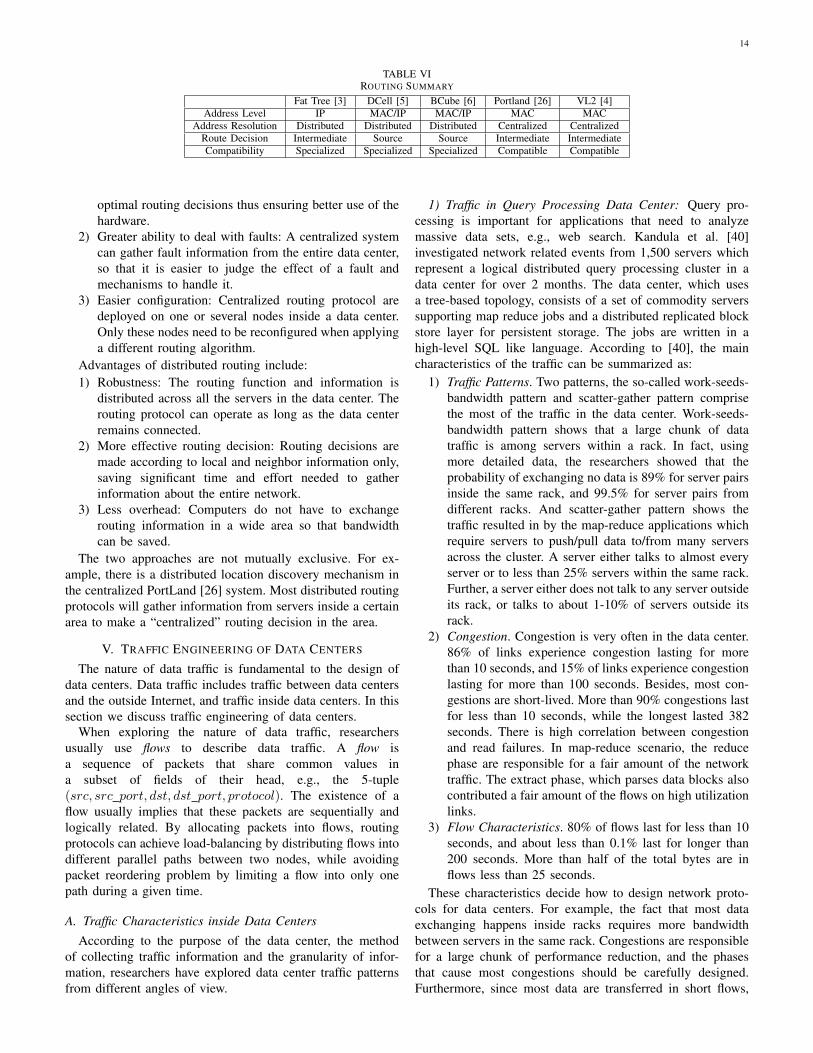
Earlier in this section, several routing mechanisms designedfor different architectures are discussed. Now the differentschemes are compared, and from this comparison some basicguidelines for designing path selection algorithms for a datacenter network can be derived. Table VI shows the comparisonof some properties of different architectures.
1) Addressing: An addressing scheme that leverages theregular architecture of a data center network can lead toeffective routing. It has to be scalable because of the largenumber of servers in a data center. It does not necessarilyhave to follow the addressing schemes used in the Internet atlarge.
Most architectures discussed mainly use switches, eliminat-ing routers. The “switch” mentioned here works on the secondOSI layer and uses MAC addresses to identify NICs. Eliminat-ing routers makes it possible to apply layer-2 addressing andswitching in data centers, as illustrated by IV-B5 and IV-D. Itshould be noted that the addressing schemes discussed in sec-tions ??, IV-E and IV-F are not necessarily layer-3 addressing;they can be expressed in either MAC addresses or IP addresses,using routing protocols running at the corresponding layer.When routing with layer-3 addresses, the protocol stack doesnot need to be different when forwarding on Ethernet headers- IP headers are carried transparently. However, switching withlayer-2 addresses eliminates the need for intermediate nodesto analyze every packet to get the layer-3 addresses and re-encapsulate within the layer-2 frame. In data centers, wherehigh-speed, and scalable routing is required, it is meaningfulto design a new protocol stack if it actually enhances theperformance of the network.
2) Centralized and Distributed Routing: Except PortLandand VL2, all the other routing schemes discussed use adistributed approach. On the other hand, Portland and VL2can be applied to any multi-rooted tree architecture [4], [26].It is not restricted by the architecture itself to decide whetherto use a centralized approach or a distributed approach whendesigning routing protocols in a data center. Each approachhas its own advantages and disadvantages. Here some of theadvantages of each approach are summarized.
Advantages of centralized routing include:1) Optimized routing: The centralized system has the com-
plete view of the entire data center, enabling it to make
14
TABLE VIROUTING SUMMARY
Fat Tree [3] DCell [5] BCube [6] Portland [26] VL2 [4]Address Level IP MAC/IP MAC/IP MAC MAC
Address Resolution Distributed Distributed Distributed Centralized CentralizedRoute Decision Intermediate Source Source Intermediate IntermediateCompatibility Specialized Specialized Specialized Compatible Compatible
optimal routing decisions thus ensuring better use of thehardware.
2) Greater ability to deal with faults: A centralized systemcan gather fault information from the entire data center,so that it is easier to judge the effect of a fault andmechanisms to handle it.
3) Easier configuration: Centralized routing protocol aredeployed on one or several nodes inside a data center.Only these nodes need to be reconfigured when applyinga different routing algorithm.
Advantages of distributed routing include:1) Robustness: The routing function and information is
distributed across all the servers in the data center. Therouting protocol can operate as long as the data centerremains connected.
2) More effective routing decision: Routing decisions aremade according to local and neighbor information only,saving significant time and effort needed to gatherinformation about the entire network.
3) Less overhead: Computers do not have to exchangerouting information in a wide area so that bandwidthcan be saved.
The two approaches are not mutually exclusive. For ex-ample, there is a distributed location discovery mechanism inthe centralized PortLand [26] system. Most distributed routingprotocols will gather information from servers inside a certainarea to make a “centralized” routing decision in the area.
V. TRAFFIC ENGINEERING OF DATA CENTERS
The nature of data traffic is fundamental to the design ofdata centers. Data traffic includes traffic between data centersand the outside Internet, and traffic inside data centers. In thissection we discuss traffic engineering of data centers.
When exploring the nature of data traffic, researchersusually use flows to describe data traffic. A flow isa sequence of packets that share common values ina subset of fields of their head, e.g., the 5-tuple(src, src port, dst, dst port, protocol). The existence of aflow usually implies that these packets are sequentially andlogically related. By allocating packets into flows, routingprotocols can achieve load-balancing by distributing flows intodifferent parallel paths between two nodes, while avoidingpacket reordering problem by limiting a flow into only onepath during a given time.
A. Traffic Characteristics inside Data CentersAccording to the purpose of the data center, the method
of collecting traffic information and the granularity of infor-mation, researchers have explored data center traffic patternsfrom different angles of view.
1) Traffic in Query Processing Data Center: Query pro-cessing is important for applications that need to analyzemassive data sets, e.g., web search. Kandula et al. [40]investigated network related events from 1,500 servers whichrepresent a logical distributed query processing cluster in adata center for over 2 months. The data center, which usesa tree-based topology, consists of a set of commodity serverssupporting map reduce jobs and a distributed replicated blockstore layer for persistent storage. The jobs are written in ahigh-level SQL like language. According to [40], the maincharacteristics of the traffic can be summarized as:
1) Traffic Patterns. Two patterns, the so-called work-seeds-bandwidth pattern and scatter-gather pattern comprisethe most of the traffic in the data center. Work-seeds-bandwidth pattern shows that a large chunk of datatraffic is among servers within a rack. In fact, usingmore detailed data, the researchers showed that theprobability of exchanging no data is 89% for server pairsinside the same rack, and 99.5% for server pairs fromdifferent racks. And scatter-gather pattern shows thetraffic resulted in by the map-reduce applications whichrequire servers to push/pull data to/from many serversacross the cluster. A server either talks to almost everyserver or to less than 25% servers within the same rack.Further, a server either does not talk to any server outsideits rack, or talks to about 1-10% of servers outside itsrack.
2) Congestion. Congestion is very often in the data center.86% of links experience congestion lasting for morethan 10 seconds, and 15% of links experience congestionlasting for more than 100 seconds. Besides, most con-gestions are short-lived. More than 90% congestions lastfor less than 10 seconds, while the longest lasted 382seconds. There is high correlation between congestionand read failures. In map-reduce scenario, the reducephase are responsible for a fair amount of the networktraffic. The extract phase, which parses data blocks alsocontributed a fair amount of the flows on high utilizationlinks.
3) Flow Characteristics. 80% of flows last for less than 10seconds, and about less than 0.1% last for longer than200 seconds. More than half of the total bytes are inflows less than 25 seconds.
These characteristics decide how to design network proto-cols for data centers. For example, the fact that most dataexchanging happens inside racks requires more bandwidthbetween servers in the same rack. Congestions are responsiblefor a large chunk of performance reduction, and the phasesthat cause most congestions should be carefully designed.Furthermore, since most data are transferred in short flows,

15
it is not sufficient to schedule long flows only.2) SNMP Data from Multiple Data Centers: Benson et al.
[41] analyzed data center traffic characteristics with the SNMPdata collected from 19 commercial data centers, which supporta wide range of applications including search, video streaming,instant messaging, map-reduce and web applications. All ofthese data centers use tree-based topologies, with componentsdistributed in different levels. The researchers offered macro-scopic view and microscopic view for the data traffic.
• Macroscopic View. Data shows that utilization is sig-nificantly higher in core layer than in aggregation andedge layers, and edge links have higher utilization thanaggregate links because of their low capacities. Althoughhaving highest utilization, core layer suffers least lossrates (expressed by the percentage of data discarded).Aggregation level has the highest loss rate. Anotherimportant observation is that most packets (about 50%)can be put into two groups according to their length:around 40B and around 1500B. While 1500B is thelength of MTU, 40B is the typical length of controllingmessages.
• Microscopic View. The researchers use another data setwhich is comprised of packet traces collected from fiveswitches of one of the data centers to get a more fine-grained view of data center traffic. The data showsthat packet arrivals follow an ON/OFF pattern, whichmeans that most packets arrive in groups and there areobvious intervals between these groups. It is shown in[41] that lognormal curve produces the best fit to boththe distributions of interval times (the OFF periods) andthe ON periods.
3) Other Traffic Patterns: Besides the two papers above,there are analysis for certain traffic patterns in other literatures.Alizadeh et al. [42] show that
VI. DATA CENTER TRANSPORT PROTOCOLS
Although many researchers assume that data center net-works use the standard TCP, there are significant proposalsin designing special network protocols suitable for data centernetworks. Each of them emphasizes special features of datacenter networks and optimizes some performance metrics.
A. Data Center TCP (DCTCP)
Alizadeh et al. proposed DCTCP, a TCP-like protocoldesigned for data centers in [42]. The goal of DCTCP is toachieve high burst tolerance, low latency and high throughputwith commodity shallow-buffered switches. DCTCP achievesthese goals by reacting to congestion in proportion to theextent of congestion. It uses a marking scheme at switches thatsets the Congestion Experienced (CE) codepoint of packets assoon as the buffer occupancy exceeds a fixed small threshold.The source node reacts by reducing the window by a factorwhich depends on the fraction of marked packets: the larger thefraction, the bigger the decrease factor. The DCTCP algorithmconsists of three main components:
1) Simple Marking at the Switch: There is only one param-eter - the marking threshold K. A packet is marked with
the CE codepoint if the queue occupancy is larger thanK on its arrival.
2) ECN(Explicit Congestion Notification)-Echo at the Re-ceiver: Unlike standard TCP, the way information inthe CE codepoint of a received packet in DCTCP isconveyed back to the sender. DCTCP achieves thissetting the received code point in the ACK packetheader. However, to reduce the load on the data center,Delayed ACKs are used. One cumulative ACK for everym consecutively received packets.
3) Controller at the Sender: The sender maintains an esti-mate of the fraction of packets that are marked, which isupdated once for every window of data. After estimatingthis fraction the sender decides whether the networkis experiencing a congestion event, and changes thewindow size accordingly. This is unlike in standard TCPwhere congestion events detected with triple-duplicateACKs lead to a halving of the congestion window.
DCTCP maintains most of the other TCP features suchas Slow Start, additive increase in congestion avoidance andrecovery from packet loss.
B. Safe and Effective Fine-grained TCP Retransmissions forData Centers
VII. PERFORMANCE ENHANCEMENT
We discussed some basic routing schemes for varioustopologies in section IV. These technologies establish andmaintain connections in data center networks. However, asdescribed in III-D3, most data center networks offer hardwareredundancy. Hardware redundancy is not only useful in dealingwith potential failures, but can also be exploited to enhancenetwork performance when there are no failures. In thissection, we discuss several approaches proposed by researchto exploit the hardware redundancy to enhance network per-formance under non-faulty conditions; using hardware redun-dancy to deal with faults will be discussed in section VIII.
A. Centralized Flow Scheduling in Fat Tree
Al-Fares et al. propose a centralized flow scheduler forfat tree in [3]. Large flows that last relatively long timeare the main concern. It is assumed in this scheme that atmost one large flow originates from one host at a time. Onlytwo kinds of components, the edge switches and the centralflow scheduler take part in the management of flows. Anedge switch assigns a new flow to its least loaded port bylocal judgment. However, it will keep tracking the growth ofthese flows. Once a flow grows above a threshold, the edgeswitch will send a notification to the central scheduler with theinformation of large flows. The central scheduler is responsiblefor reassigning paths to large flows. It will keep track of allthe large flows in the network. When it gets notification of anew inter-pod large flow, it scans the core switches to find onewhich is on a path without reserved links. On finding such apath, the central scheduler will mark all its links as reserved,and inform the relevant switches on the path. For intra-podlarge flows, the central scheduler only needs to carry out a

16
scan on the aggregation switches in that pod and find onepath without reserved link. When a flow is not updated for agiven period of time, the central scheduler will decide that theflow is no longer active, and clears the reservations. Duringthe execution of the procedure scanning and path assigningmentioned above, the originating edge switch of the large flowwill continue to transmit it rather than stop and wait.
1) Hedera’s Flow Scheduling for Fat Tree: Hedera, anothercentralized flow scheduling system for fat tree, is proposed in[27]. Hedera detects large flows at edge switches, and selectsa path according to the result of the estimated demand of largeflows.
Network flow can be limited by the bandwidth betweenthe source and destination, or the capacity of the ports onthem. Hedera considers the bandwidth limitation only. Thetarget of demand estimation is to fairly assign all availablebandwidth to existing flows. Hedera uses a N × N matrixto estimate the demand of all flows, where N is the totalnumber of computers. An element [i, j] contains 3 values: thenumber of flows from computer i to computer j, the estimateddemand of each of the flows, and a flag marking whether thedemand of a flow has converged (i.e., fully utilizing availablebandwidth without limiting other flows). It is assumed thatmultiple flows from the same source to the same destinationhas the same demand, and all the demands are expressed inpercentages, assuming that the bandwidth between any twocomputers are the same. The original values consider thecapacity of sources only. The idea of the algorithm is to repeatiterations of increasing the flow capacities from the sourcesand decreasing exceeded capacities at the receivers until alldemands converge.
A simulated annealing algorithm is used to design a sched-uler in [27]. The definitions of the elements of the algorithmis as follows:
• State s: a set of mappings from destination computers tocore switches. Each computer is assigned to a core switchthrough which the incoming flows of the computer aretransmitted. By limiting each computer to a core switch,the cost of searching paths can be significantly reduced,although the result may not be globally optimal.
• Energy function E: the total exceeded capacity of thecurrent state.
• Temperature T : number of remaining iterations.• Neighbor generator function: swaps the assigned core
switches of a pair of computers in the current state sto get a neighbor state sn.
• Acceptance probability P : the possibility of the transitionfrom current state s to a neighbor state sn. P is a functionof T , E, En, where
P (En, E, T ) =
{1, En < Eec(E−En)/T , En ≥ E
c is a constant. It is suggested in [27] to use c = 0.5×T0
for 16-host cluster and c = 1000 × T0 for larger datacenters.
In each iteration of the simulated annealing algorithm, itwill jump to a neighbor state sn with possibility P , anddecrease the temperature T . When T drops to 0, the algorithm
is finished. Allowing jumping to a state with higher energy canavoid local minima.
2) Random Traffic Spreading of VL2: VL2 [4] makes useof two techniques to offer hot-spot-free performance: VLB(Valiant Load Balancing) and ECMP (Equal Cost MultiPath).
VL2 implements VLB by sending flows through arandomly-chosen intermediate switch, and ECMP by distribut-ing flows across paths with equal cost. Path selection of VLBand ECMP is random, which means no centralized coordina-tion and traffic engineering is needed. However, if there arelarge coexisting flows, random distribution of flows may leadto persistent congestion on certain links while leaving otherlinks idle. According to the results shown in [4], this does notbecome a real problem for the tree-based architecture that theresearchers used.
B. BCube Source Routing
BCube Source Routing (BSR) [6] is a source routingprotocol designed for BCube architecture. In source routingthe entire route is decided by the source itself, and it will insertthe routing information in the header of every packet. By doingthis, the source can control the path without the coordinationof intermediate nodes. Besides, the intermediate nodes justneed to forward the packets according to the information inthe header, which can simplify their functionalities. Beforeintroducing BSR, we start from addressing and simple routingin BCube.
It should be noted that BCubeRouting only uses singlepaths to transfer the packets between two computers, whileaccording to the order of changing the digits in the addresses,there can be k + 1 parallel paths between two computers.Thus BCubeRouting wastes most of the network capacity ofBCube. To fully utilize the high capacity of BCube and enableautomatic load-balancing, BSR is proposed in [6]. In BSR, thenetwork traffic is divided into flows.
BSR uses a reactive mechanism. On receiving a new flow,the source node sends probe packets along multiple parallelpaths towards the destination. Intermediate nodes reply to theprobe packets with necessary information about link state.With the information returned from intermediate nodes, thesource can make routing decisions. When the source receivesthe responses, it will calculate a metric from the information,and select the best path. When this path selection procedureis performed, the source node will not hold the flow packetsinto a buffer, instead, it will initially choose a path from theparallel paths set to start transmitting. After the path selectionis completed and a new path is selected, the source nodewill switch the flow to the better new path. This may causetemporal packet reordering. Considering that path selectioncan be done in a short time, the switching will not poseperformance problem.
The links used by a flow may break during transmission.To address this problem, the source node sends probes pe-riodically to detect network failures. When an intermediatenode finds the next hop of a packet is failed, it will senda path failure message to the source node. The source willimmediately switch the flow to the next best path in the parallel
17
paths set. Then, after the periodical probing timer expires, thesource will start a new round of path selection. Doing this canavoid packet buffering when failure occurs.
When there are multiple concurrent flows between twonodes, they may be distributed to the same path. Besides, theywill perform periodical probing at the same time. To avoid thispath oscillation, a random value can be injected into the timerof periodical path selection.
C. Traffic De-multiplexing in c-Through
Hybrid networks such as c-Through[7] face a special prob-lem: how to assign traffic into two different types of network,electrical and optical. In c-Through, the problem is solved byusing VLAN-based routing. The ToR switches are assignedinto two different VLANs which are logically separated. Thisdistinguishes the optical network from the electrical network.Since the optical VLAN may be reconfigured frequentlyaccording to the changing traffic, spanning tree protocol isdisabled in optical VLAN due to its long convergence time.At server side, a management daemon is run on each serverto de-multiplex traffic to the optical and electrical network.The assigned path of each packet is decided according toits destination. In practice, to make more efficient use ofthe optical network, the optically-connected destinations willhave higher transmission priority compared to electrically-connected destinations.
D. Summary of Performance Enhancement Technologies
The technologies we discussed above uses the abundanthardware redundancy available in the data center networksto get better performance. In this section we summarizethese technologies to find some guidelines to design routingtechniques with better performance. Table VII shows the com-parison of different performance enhancement technologies.
1) Multi-path Routing: The hardware redundancy of thedata center networks enables multi-path routing, which canmake better use of the idle components, and avoid overloadedcomponents. Some conditions must be met when multi-pathrouting is used:
1) There must be hardware redundancy. Topologies such asbasic tree have no hardware redundancy. There is onlyone deterministic path between two computers, so nomulti-path routing can be applied.
2) Multi-path routing should be able to achieve fairnesswhen assigning data transmission to a path, i.e., datatraffic should be dispersed, and every path is not neces-sarily the “best” path. (The meaning of “best” is decidedaccording to the metric used to evaluate a path; forexample, a best path can be a path with least latency, orlargest bandwidth.)
3) Paths may overlap at some links/nodes.It should be noted that in data centers with hardware
redundancy, even if source routing is not used, there can beother ways to make use of the idle redundant links: nodescan detour packets according to local information about thenetwork conditions. This is also referred to as detour routing.
It offers a more flexible way to make use of idle links.The disadvantage of detour routing is that there must bemechanisms to avoid possible rings.
A node need not to be able to send data packages throughmultiple links concurrently to the same destination. The multi-ple links can be stored at the source node, and take effect onlywhen the current path being used fails. However, the abilityof using multiple links concurrently is helpful to dispersedata traffic more evenly, which requires more careful designto avoid reordering of sequential packets. Flow scheduling isdesigned to address this problem.
2) Flow Scheduling: Grouping data into flows helps re-searchers to get a better view of data transmissions in datacenters so that the routing protocols can achieve fairness andefficiency in large scale. Typically the data to identify a flow isintercepted by the routing protocol and judged by the protocolitself. No special field inside a data packet such as flow id isdefined to identify a flow, because that would need redesignof the whole network layer.
Flow scheduling is meaningful only when there are multipleoptional paths, so that different flows can be placed ondifferent paths according to their capability. There are twoapproaches to direct a flow: decide the whole path of theflow at the source, or make routing decisions at intermediatenodes. The latter approach needs every intermediate node toidentify a flow again and again, while in the former approachintermediate nodes only need to extract routing informationfrom a packet and send it to the next hop on the path.
Flow scheduling solves the reordering problem introducedby multi-path routing. The data packets in the same flow aretransferred sequentially without being reordered.
Flow scheduling needs to gather information from the firstpackets of a flow, while at the same time these packets mayhave been sent out through different paths. According tocurrent research [40] of flows in data centers, more than 80%of flows last less than 10 seconds, while only less than 0.1% offlows last more than 2000 seconds. On the other hand, 50%of data are in flows lasting less than 25 seconds. The mainchallenges in scheduling flows include:
1) It is impossible to predict whether a flow is a large flow;if two large flows are routed to the same path, the trafficwill be unbalanced.
2) The first packets of a flow may be reordered. Given thatmost flows last a short time, and most data are in theseshort flows, the reordering problem still cannot be solvedwell.
To solve the first problem, changing the path of a flowduring its transmission should be allowed to keep networktraffic balanced, although it may lead to packet reordering.For the second problem, maintaining a buffer at the sourcemay help, but it may be expensive, and increase latency.
VIII. FAULT TOLERANT ROUTING
Considering the large number of computers and switchesused in a data center, it is unlikely that the system can keeprunning without failures throughout its lifetime. A data centernetwork must be designed to be able to recover automatically

18
TABLE VIIPERFORMANCE ENHANCEMENT TECHNIQUES
Fat Tree [3] BCube [6] Hedera [27] VL2 [4]Flow Scheduling Reassign Paths for Metric-based Simulated Random Path
Algorithm Large Flows Routing Annealing SelectionDecision Maker of Central Scheduler Source Edge Switches Source
Multi-path Selection Node Node
from common failures, and maintain most of its performancein the meantime. On hardware level, most data center topolo-gies employ redundant links to ensure connectivity in case ofhardware failures. Moreover, the routing mechanisms runningabove make use of the redundancy offered by the hardware torecover from communication failures. Since we have discussedhardware redundancy in III-D3, we will turn to the softwaremechanisms, i.e., the fault tolerant routing protocols used bydifferent data center networks.
A. Fault Models
Failures in data centers may be caused by different com-ponents. Classifying the failures into fault models helps tofigure out the characteristics of different failures and methodsto detect and deal with certain types of failures. Failures canbe classified based on the following aspects.
1) Failure Type: This attribute identifies the level at whichcomponents are diagnosed as having failed [35]. Either thewhole component fails, or one of the links connected to itfails. The former is referred to as node failure, and the latteras link failure.
For components such as the computers in a fat trees, thathave only one link, node failure and link failure have thesame effect. On the other hand, a node failure of a nodewith multiple links can be considered as link failures for allits links. A mechanism that can deal with link failures canalso deal with node failures. However, this does not precludethe need for distinguishing between node failures and linkfailures. For example, marking a node as failed means thatthe routing protocol can choose to detour around that nodewithout checking its links one by one, thus saving significanttime.
It should be noted that link failures and node failures arenot necessarily hardware failures. The real meaning of a linkfailure or node failure is that a link or all the links connectedto a component are no longer feasible to transmit data fromthe application’s point of view.
2) Fault Region: A fault region is a useful concept whenmultiple related components are faulty. For example, in adata center constructed of racks, power failure of a rack willdisconnect all the components in the rack. If a routing protocolcan figure out rack failures, it can detour the whole rack. Sincethe positioning of the components may vary, it depends on thephysical architecture and logical architecture of a data centerto define its fault regions.
3) Fault Neighborhood: This attribute reflects the extent ofdissemination of fault information. According to the distancefrom the faulty node to the selected node, there can be 3different modes: global, in which every node in the networkhas the information of all faulty nodes; local, in which only the
adjacent nodes of a faulty node are aware of its information;k-neighborhood, only the information of faulty nodes withindistance (usually using hops to express the distance) k istracked. The global mode can help to make better route choicesbased on global information, while needs more storage andperiodic global synchronization. On the other hand, routingbased on local information is simpler and faster, while maylead to longer paths. The k-neighborhood mode can make abalance between the two extreme conditions.
4) Failure Mode: This attribute shows the duration offailures. A static failure is present since the system starts up,while a dynamic failure occurs during the operation of thesystem. Both kinds of failures are considered to be permanent.In contrast, a fault can be transient. Dynamic failures andtransient failures are the main challenge when designing arouting protocol.
5) Failure Time: This attribute shows the frequency of com-ponent failures. Two values, the mean time between failures(MTBF) and mean time to repair (MTTR) are used to evaluatethe possibility of a failure and the time needed to recover fromit. For example, if MTBF and MTTR are close for one kind ofcomponent, it is likely that there will be multiple concurrentfaulty components in the data center. According to the researchof MTTR in [4], 95% of failures are resolved in 10 minutes,98% in less than an hour, 99.6% in less than a day, but 0.09%failures last for more than 10 days. These percentiles mayvary in data centers using different hardware, but can serve asa reference for the distribution of MTTR.
6) Taxonomy of Faults: Figure 10 shows a taxonomy offault models we have mentioned. One fault can be classifiedinto multiple models. Although one routing protocol may notmake use of all of the models above, distinguishing differentfaults with these models will help a routing protocol to dealwith faults according to their characteristics.
B. Link Failure Response in Fat Tree
Al-Fares et al. [3] proposed a failure broadcast protocolto detect link failures in fat tree architecture. The architectureonly discusses simplest link failures, without mentioning otherfault models in VIII-A.
As described in III-D3, there is no redundancy link betweena computer and an edge switch, and the only way to deal withsuch a failed link is to add extra links between computersand edge switches. On the other hand, link failures betweenswitches can be classified as:
• between edge switches (lower in a pod) and aggregationswitches (upper in a pod);
• between aggregation switches and core switches.A Bidirectional Forwarding Detection session (BFD [43])
is used to detect link failures. The protocols exploits different

19
Failure Type
Fault Region
Failure Mode
Failure Time
Fault Neighborhood
Faults
Node Failure Link Failure
Region
Static Dynamic Transient
MTTR MTBF
Local Global k-neighborhood
Fig. 10. A Taxonomy for Faults
mechanisms to deal with the two kinds of link failures. For alink failure between an edge switch and an aggregation switch,three kinds of traffic may be affected:
1) Outgoing traffic originated by a computer connected tothe edge switch. In this case, the edge switch will detectthe link failure, the cost of the link will be set to infinityand another available link will be chosen.
2) Intra-pod traffic that uses the aggregation switch as anintermediary. In this case this aggregation switch detectsthe link failure, and will broadcast this link failure toevery other edge switch in the pod, and they will try todetour this link.
3) Inter-pod traffic coming to the aggregation switch froma core switch. In this case, the aggregation switchdetects the link failure, and will broadcast this failureto all the core switches. The core switches then informall aggregation switches, so that they will detour theaffected core switch when sending traffic to the subnetconnected to the edge switch.
For a link failure between an aggregation switch and a coreswitch, two kinds of traffic may be affected:
1) Outgoing inter-pod traffic. In this case the failure isdetected by the aggregation switch. It will set this linkas unavailable, and simply choose the link to anothercore switch.
2) Incoming inter-pod traffic. In this case the failure isdetected by the core switch. In this case it will broad-cast this link failure to all other aggregation switchesconnected to it, announcing that it cannot send traffic tothat pod. The aggregation switches will detour this coreswitch when trying to send traffic to that pod.
When the failed link is recovered, it will be detected by theBFD session, and the measures above will be reversed. We cansee that in this fault tolerant scheme the fault information issent to nodes at most two hops away, so it uses 2-neighborhoodmode.
1) Fault Tolerant Routing in PortLand and Hedera: Niran-jan Mysore et al. [26] proposed a fault tolerant routing schemefor PortLand, which also uses link failure to represent allpossible failures. Since PortLand exploits a centralized fabricmanager to maintain the entire network, it is more effective
in gathering and spreading fault messages. The periodic LDMmentioned in IV-B4 can also serve as probe of link failures.If a node does not receive LDM for a certain period of time,it will assume that a link failure has occurred and send theinformation to the fabric manager. The fabric manager usesa fault matrix to store the status of each link in the wholenetwork. On receiving a fault message, the fabric managerupdates the fault matrix, and informs all the affected nodesof this link failure. These nodes will reroute with the newinformation. On recovery of a link failure, the procedure issimilar except that the information is a recovery messageinstead of a fault message. With the fabric manager, the extentof the fault information can be easily controlled. Besides, byusing multicast instead of broadcast, the cost of spreading thefault message can be reduced to minimum.
Hedera [27], whose implementation augments PortLandrouting and fault tolerant protocols, has the same mechanismsof dealing with failures.
C. DCell Fault-tolerant Routing
DCell Fault-tolerant Routing (DFR) uses DCellRouting andDCellBroadcast to enable fault-tolerant routing in DCell. Itdefines three types of failures: server failure, rack failure andlink failure, and it uses three techniques, local reroute, locallink-state and jump-up to deal with these failures respectively.
• Local Reroute: bypass a link failure according to localdecisions only. When a link failure occurs, local reroutewill be done at one of the two ends of the failed link.If the failed link (n1, n2) is a level-l link (i.e., the twoends of the link is in the same DCelll but in differentDCellk−1s), n1 will choose a node in another DCellk−1
that does not contain n2 as its proxy. As long as not alllinks from n1’s DCellk−1 to other DCellk−1s are failed,such a proxy can always be found. After the proxy isselected, DCellRouting will be executed on the proxy tofind a path to the destination. Local reroute may transmitthe packet to the other end of a failed link, and if it is afailed node, local reroute cannot bypass it.
• Local Link-state: use link-state information gathered withDCellBroadcast to bypass node failures. By means ofDCellBroadcast, a node in a DCellb (the range of a

20
broadcast packet is delivered, where number b is definedaccording to hardware capability, generally contains arack of switches and the computers connected to them)can know the status of all the links connecting its ownDCellb and other DCellbs. In this scheme, a node willcalculate the route inside its DCellb local with link-state information and the Dijkstra algorithm. When a linkfailure happens, the node will invoke local-reroute to finda proxy. Since the decision is made upon link-state of thewhole DCellb, no matter whether the link failure impliesa potential node failure, the failed node can be bypassed.
• Jump-up: a scheme to address rack failure, in which thewhole DCellb fails. In local link-state, when a wholeDCellb in a path fails, the packet will be re-routedendlessly round the DCellb. To address such kind offailure, the jump-up scheme is introduced. When a linkfailure is detected, and the first attempt to re-route toanother path in the DCellb is unsuccessful, it will beassumed that the whole DCellb, i.e., the whole rackis down. Then the receiver of the re-routed packet will“jump-up” to a higher level DCell to bypass the wholefailed DCellb. Besides, since it is impossible to reach anode inside a failed DCellb, a time-to-live (TTL) field isadded into every packet to avoid endless re-routing.
By using all the techniques above, DFR can handle linkfailure, node failure and rack failure.
D. Fault Tolerant Routing in BCube
As discussed in VII-B, BCube can detect link failures bysending periodic probes, and turn to backup paths when failureoccurs.
E. Summary of Fault Tolerant Routing Protocols
We discussed some fault tolerant routing techniques inthis section. From a comparison between them, we can findsome guidelines of designing fault tolerant routing protocols.Table VIII gives some comparisons between the fault toleranttechniques we discussed. Some of them are not mentionedin this section but in previous sections, because performanceenhancement techniques sometimes can also serve as faulttolerant techniques.
1) All these protocols have their own mechanisms to detectlink failures. Since node failures can be viewed as a setof link failures, being able to deal with link failures alsomeans being able to deal with node failures or failuresaffecting even more components, e.g, rack failures.
2) The MTTR and MTBF of different components shouldbe considered when designing fault tolerant mecha-nisms, e.g., when deciding the frequency of runningfailure detecting processes.
3) Spreading failure information can reduce the timewasted to wait for a timeout. However, this may involvenon-related nodes, and updating such information mayoccupy a lot of bandwidth.
4) Protocols should be designed to discover componentsrecovered from failure.
Some fault tolerant techniques such as keeping back-uproutes in routing tables can serve to enhance performancewhen there are no faults. It is meaningful to consider bothaspects together when designing the routing protocol.
IX. CONCLUSIONS
In this survey, we discussed some representative topolo-gies of data center networks. We discussed the properties ofthese topologies, the routing protocols designed for them, thetechniques for enhancing their performance, and fault toler-ant techniques. Researchers are still proposing potential newtopologies for future data center networks. Any topology has tostrike a balance between performance, cost and sustainability.
ACKNOWLEDGMENT
The work described in this paper has been supported byHK RGC under RGC-Competitive Earmarked Research GrantHKUST 617907.
REFERENCES
[1] M. Armbrust, A. Fox, R. Griffith, A. D. Joseph, R. H. Katz,A. Konwinski, G. Lee, D. A. Patterson, A. Rabkin, I. Stoica,and M. Zaharia, “Above the clouds: A berkeley view of cloudcomputing,” EECS Department, University of California, Berkeley,Tech. Rep. UCB/EECS-2009-28, Feb 2009. [Online]. Available:http://www.eecs.berkeley.edu/Pubs/TechRpts/2009/EECS-2009-28.html
[2] A. Greenberg, J. Hamilton, D. A. Maltz, and P. Patel, “The cost of acloud: research problems in data center networks,” SIGCOMM Comput.Commun. Rev., vol. 39, no. 1, pp. 68–73, 2009.
[3] M. Al-Fares, A. Loukissas, and A. Vahdat, “A scalable, commodity datacenter network architecture,” in Proceedings of the ACM SIGCOMM2008 conference on Data communication. ACM, 2008, pp. 63–74.
[4] A. Greenberg, J. R. Hamilton, N. Jain, S. Kandula, C. Kim, P. Lahiri,D. A. Maltz, P. Patel, and S. Sengupta, “Vl2: a scalable and flexible datacenter network,” SIGCOMM Comput. Commun. Rev., vol. 39, no. 4, pp.51–62, 2009.
[5] C. Guo, H. Wu, K. Tan, L. Shi, Y. Zhang, and S. Lu, “DCell: A scalableand fault-tolerant network structure for data centers,” ACM SIGCOMMComputer Communication Review, vol. 38, no. 4, pp. 75–86, 2008.
[6] C. Guo, G. Lu, D. Li, H. Wu, X. Zhang, Y. Shi, C. Tian, Y. Zhang, andS. Lu, “Bcube: A high performance, server-centric network architecturefor modular data centers,” ACM SIGCOMM Computer CommunicationReview, vol. 39, no. 4, pp. 63–74, 2009.
[7] G. Wang, D. Andersen, M. Kaminsky, K. Papagiannaki, T. Ng,M. Kozuch, and M. Ryan, “c-through: Part-time optics in data centers,”in ACM SIGCOMM Computer Communication Review, vol. 40, no. 4.ACM, 2010, pp. 327–338.
[8] N. Farrington, G. Porter, S. Radhakrishnan, H. Bazzaz, V. Subramanya,Y. Fainman, G. Papen, and A. Vahdat, “Helios: a hybrid electrical/opticalswitch architecture for modular data centers,” in ACM SIGCOMMComputer Communication Review, vol. 40, no. 4. ACM, 2010, pp.339–350.
[9] K. Chen, A. Singla, A. Singh, K. Ramachandran, L. Xu, Y. Zhang,X. Wen, and Y. Chen, “Osa: An optical switching architecture fordata center networks with unprecedented flexibility,” in Proceedingsof the 9th USENIX conference on Networked Systems Design andImplementation. USENIX Association, 2012, pp. 18–18.
[10] K. Chen, C. Hu, X. Zhang, K. Zheng, Y. Chen, and A. Vasilakos, “Surveyon routing in data centers: insights and future directions,” Network,IEEE, vol. 25, no. 4, pp. 6–10, 2011.
[11] M. Bari, R. Boutaba, R. Esteves, L. Granville, M. Podlesny, M. Rabbani,Q. Zhang, and M. Zhani, “Data center network virtualization: A survey,”Communications Surveys Tutorials, IEEE, vol. PP, no. 99, pp. 1 –20,2012.
[12] C. Kachris and I. Tomkos, “A survey on optical interconnects for datacenters,” Communications Surveys Tutorials, IEEE, vol. 14, no. 4, pp.1021 –1036, quarter 2012.

21
TABLE VIIIFAULT TOLERANT TECHNIQUES
Fat Tree [3] DCell [5] BCube [6] PortLand [26]& Hedera [27]
Failure Types Link FailureLink Failure/
Link Failure Link FailureServer Failure/Rack Failure
Failure Detecting BFD DCellBroadcast Periodic LDMMechanisms (Periodic Probes) (Reactive Probes) Probes (Periodic Probes)
Area of Spreading Edge/ Local/Source
All NodesFailure Information Aggregation/ Rack/ on the Path
Core Inter-rackDecision Maker Intermediate Intermediate Source Fabric Manager
[13] K. Wu, J. Xiao, and L. Ni, “Rethinking the architecture design of datacenter networks,” Frontiers of Computer Science, vol. 6, pp. 596–603,2012. [Online]. Available: http://dx.doi.org/10.1007/s11704-012-1155-6
[14] H. Zimmermann, “OSI reference model–The ISO model of architecturefor open systems interconnection,” Communications, IEEE Transactionson, vol. 28, no. 4, pp. 425–432, 1980.
[15] K. Kant, “Data center evolution: A tutorial on state of the art, issues,and challenges,” Computer Networks, vol. 53, no. 17, pp. 2939–2965,2009.
[16] N. Boden, D. Cohen, R. Felderman, A. Kulawik, C. Seitz, J. Seizovic,and W. Su, “Myrinet: A Gigabit-per-Second Local Area Network,” IEEEMicro, vol. 15, no. 1, pp. 29–36, 1995.
[17] L. Ong and J. Yoakum, “An Introduction to the StreamControl Transmission Protocol (SCTP),” RFC 3286 (Informational),Internet Engineering Task Force, May 2002. [Online]. Available:http://www.ietf.org/rfc/rfc3286.txt
[18] C. Perkins, “IP Mobility Support,” RFC 2002 (ProposedStandard), Internet Engineering Task Force, Oct. 1996, obsoletedby RFC 3220, updated by RFC 2290. [Online]. Available:http://www.ietf.org/rfc/rfc2002.txt
[19] Hyper-v quick migration basp team connectivity loss - ibmbladecenter and system x. [Online]. Available: http://www-947.ibm.com/support/entry/portal/docdisplay?lndocid=migr-5087137
[20] D. Thaler and C. Hopps, “Multipath Issues in Unicastand Multicast Next-Hop Selection,” RFC 2991 (Informational),Internet Engineering Task Force, Nov. 2000. [Online]. Available:http://www.ietf.org/rfc/rfc2991.txt
[21] IEEE Standards Association, “Media access control (mac) bridges andvirtual bridge local area networks,” 2011.
[22] C. Kim, M. Caesar, and J. Rexford, “Floodless in seattle: a scalable eth-ernet architecture for large enterprises,” in ACM SIGCOMM ComputerCommunication Review, vol. 38, no. 4. ACM, 2008, pp. 3–14.
[23] D. Farinacci, V. Fuller, D. Meyer, and D. Lewis, “Locator/ID separationprotocol (LISP),” Internet Draft (draft-ietf-lisp-23), May 2012, (Work inprogress).
[24] R. Perlman, D. Eastlake 3rd, D. Dutt, S. Gai, and A. Ghanwani, “RoutingBridges (RBridges): Base Protocol Specification,” RFC 6325 (ProposedStandard), Internet Engineering Task Force, Jul. 2011, updated by RFCs6327, 6439. [Online]. Available: http://www.ietf.org/rfc/rfc6325.txt
[25] E. Nordmark and M. Bagnulo, “Shim6: Level 3 MultihomingShim Protocol for IPv6,” RFC 5533 (Proposed Standard),Internet Engineering Task Force, Jun. 2009. [Online]. Available:http://www.ietf.org/rfc/rfc5533.txt
[26] R. Niranjan Mysore, A. Pamboris, N. Farrington, N. Huang, P. Miri,S. Radhakrishnan, V. Subramanya, and A. Vahdat, “Portland: a scalablefault-tolerant layer 2 data center network fabric,” ACM SIGCOMMComputer Communication Review, vol. 39, no. 4, pp. 39–50, 2009.
[27] M. Al-Fares, S. Radhakrishnan, B. Raghavan, N. Huang, and A. Vahdat,“Hedera: Dynamic flow scheduling for data center networks,” in Pro-ceedings of the 7th USENIX conference on Networked systems designand implementation. USENIX Association, 2010, p. 19.
[28] D. Li, C. Guo, H. Wu, K. Tan, Y. Zhang, and S. Lu, “Ficonn:Using backup port for server interconnection in data centers,” in IEEEINFOCOM, 2009.
[29] H. Wu, G. Lu, D. Li, C. Guo, and Y. Zhang, “MDCube: a high per-formance network structure for modular data center interconnection,” inProceedings of the 5th international conference on Emerging networkingexperiments and technologies. ACM, 2009, pp. 25–36.
[30] H. Abu-Libdeh, P. Costa, A. Rowstron, G. O’Shea, and A. Donnelly,
“Symbiotic routing in future data centers,” ACM SIGCOMM ComputerCommunication Review, vol. 40, no. 4, pp. 51–62, 2010.
[31] C. E. Leiserson, “Fat-trees: universal networks for hardware-efficientsupercomputing,” IEEE Trans. Comput., vol. 34, no. 10, pp. 892–901,1985.
[32] W. Dally and B. Towles, Principles and practices of interconnectionnetworks. Morgan Kaufmann, 2004.
[33] J. Edmonds, “Paths, trees, and flowers,” Canadian Journal of mathemat-ics, vol. 17, no. 3, pp. 449–467, 1965.
[34] M. Muller-Hannemann and A. Schwartz, “Implementing weighted b-matching algorithms: insights from a computational study,” Journal ofExperimental Algorithmics (JEA), vol. 5, p. 8, 2000.
[35] J. Duato, S. Yalamanchili, and L. Ni, Interconnection networks: Anengineering approach. Morgan Kaufmann, 2003.
[36] L. Bhuyan and D. Agrawal, “Generalized hypercube and hyperbusstructures for a computer network,” IEEE Transactions on Computers,pp. 323–333, 1984.
[37] M. Hamdi and R. Hall, “Rcc-full: An effective network for parallelcomputations,” Journal of Parallel and Distributed Computing, vol. 41,no. 2, pp. 139–155, 1997.
[38] Y. Zhang, A. Sub, and G. Jiang, “Understanding data center networkarchitectures in virtualized environments: A view from multi-tier appli-cations,” Computer Networks, vol. 55, pp. 2196–2208, 2011.
[39] L. Popa, S. Ratnasamy, G. Iannaccone, A. Krishnamurthy, and I. Stoica,“A cost comparison of datacenter network architectures,” in Proceedingsof the 6th International COnference. ACM, 2010, p. 16.
[40] S. Kandula, S. Sengupta, A. Greenberg, P. Patel, and R. Chaiken, “Thenature of data center traffic: measurements & analysis,” in Proceedingsof the 9th ACM SIGCOMM conference on Internet measurement con-ference. ACM, 2009, pp. 202–208.
[41] T. Benson, A. Anand, A. Akella, and M. Zhang, “Understanding datacenter traffic characteristics,” in WREN ’09: Proceedings of the 1st ACMworkshop on Research on enterprise networking. New York, NY, USA:ACM, 2009, pp. 65–72.
[42] M. Alizadeh, A. Greenberg, D. Maltz, J. Padhye, P. Patel, B. Prabhakar,S. Sengupta, and M. Sridharan, “Data center TCP (DCTCP),” ACMSIGCOMM Computer Communication Review, vol. 40, no. 4, pp. 63–74,2010.
[43] D. Katz and D. Ward, “Bfd for ipv4 and ipv6 (single hop),” draft-ietf-bfd-v4v6-1hop-09 (work in progress), 2009.
Yang Liu is a Ph.D. student in The Hong Kong University of Science andTechnology, Clear Water Bay, Kowloon, Hong Kong.

22
Jogesh K. Muppala (M’85-SM’02) received the Ph. D. degree in ElectricalEngineering from Duke University, Durham, NC in 1991. He is currently anassociate professor in the Department of Computer Science and Engineering,The Hong Kong University of Science and Technology, Clear Water Bay,Kowloon, Hong Kong. He was previously a Member of the Technical Staffat Software Productivity Consortium (Herndon, Virginia, USA) from 1991 to1992, where he was involved in the development of modeling techniquesfor systems and software. While at Duke University, he participated inthe development of two modeling tools, the Stochastic Petri Net Package(SPNP) and the symbolic Hierarchical Automated Reliability and PerformanceEvaluator (SHARPE), both of which are being used in several universitiesand industry in the USA. He was the program co-chair for the 1999 PacificRim International Symposium on Dependable Computing held in Hong Kongin December 1999. He also co-founded and organized The Asia-PacificWorkshop on Embedded System Education and Research. He has also servedon program committees of many international conferences. He receivedthe Excellence in Teaching Innovation Award 2007. He was also awardedthe Teaching Excellence Appreciation Award by the Dean of Engineering,HKUST. Dr. Muppala is a Senior Member of IEEE, IEEE Computer Societyand IEEE Communications Society, and a participating representative fromHKUST with EDUCAUSE.
Malathi Veeraraghavan is with the Charles L. Brown Department ofElectrical and Computer Engineering, University of Virginia, Charlottesville,VA 22904.