a study on thermal conductvity of epoxy…ethesis.nitrkl.ac.in/5291/1/upload_thesis.pdf · a study...
TRANSCRIPT

A STUDY ON THERMAL CONDUCTVITY OF EPOXY/Al2O3 COMPOSITES
A THESIS SUBMITTED IN PARTIAL FULFILLMENT OF
THE REQUIREMENT FOR THE AWARD OF THE DEGREE
OF
MASTER OF TECHNOLOGY IN
MECHANICAL ENGINEERING
(THERMAL ENGINEERING)
BY
ASUTOSH PANDA
(ROLL NO. 211ME3357)
Under the Guidance of
Prof. Alok Satapathy
Department of Mechanical Engineering
National Institute Of Technology Rourkela
(India)
2013

Department of Mechanical Engineering
National Institute of Technology
Rourkela
CERTIFICATE
This to certify that the thesis entitled “A Study on Thermal Conductivity of
Epoxy/Al2O3 Composites” being submitted by Asutosh Panda for the award of the
degree of Master of Technology (Thermal Engineering) of NIT Rourkela, is a record of
bonafide research work carried out by him under our supervision and guidance. Mr.
Asutosh Panda has worked for more than one year on the above problem at the
Department of Mechanical Engineering, National Institute of Technology, Rourkela and
this has reached the standard fulfilling the requirements and the regulation relating to
the degree. The contents of this thesis, in full or part, have not been submitted to any
other university or institution for the award of any degree or diploma.
Prof. Alok Satapathy Supervisor Associate Professor Department of Mechanical Engineering NIT, Rourkela

ACKNOWLEDGEMENT
This thesis is a result of research that has been carried out at National Institute
of Technology, Rourkela. During this period, I came across with a great number of
people whose contributions in various ways helped my field of research and they
deserve special thanks. It is a pleasure to convey my gratitude to all of them.
In the first place, I would like to express my deep sense of gratitude and
indebtedness to my supervisor Prof. Alok Satapathy for his advice, and guidance from
early stage of this research and providing me extraordinary experiences throughout
the work. Above all, he provided me unflinching encouragement and support in
various ways which exceptionally inspire and enrich my growth as a student, a
researcher. His involvement with originality has triggered and nourished my
intellectual maturity that will help me for a long time to come. I am proud to record that
I had opportunity to work with an exceptionally experienced scientist like him.
I am grateful to Director, Prof. S.K. Sarangi, Prof. P.K. Roy, ex-Head of
Mechanical Engineering Department, and Prof. K.P. Maity, former Head of Mechanical
Engineering Department, National Institute of Technology, Rourkela, for their kind
support and concern regarding my academic requirements.
I am indebted to Miss Debasmita Mishra, Mr. Alok Agrawal, Mr. Gaurav
Gupta,Mr.Pravat Ranjan Pati and Miss Madhusmita for their support and co-operation
which is difficult to express in words. The time spent with them will remain in my
memory for years to come.
Thanks to my co-scholars at National Institute of Technology, Rourkela, for
their whole hearted support and cooperation during the duration of this work.
My parents deserve special mention for their inseparable support and prayers.
They are the persons who show me the joy of intellectual pursuit ever since I was a
child. I thank them for sincerely bringing up me with care and love.
Last, but not the least, I thank the one above all of us, the omnipresent God, for
giving me the strength during the course of this research work.
Asutosh Panda
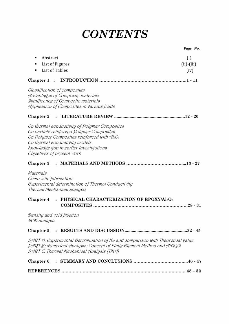
CONTENTS Page No.
Abstract (i)
List of Figures (ii)-(iii)
List of Tables (iv)
Chapter 1 : INTRODUCTION ……………………………………………………..1 - 11
Classification of composites Advantages of Composite materials Significance of Composite materials Application of Composites in various fields
Chapter 2 : LITERATURE REVIEW ............................................................12 - 20
On thermal conductivity of Polymer Composites On particle reinforced Polymer Composites On Polymer Composites reinforced with Al2O3 On thermal conductivity models Knowledge gap in earlier Investigations Objectives of present work
Chapter 3 : MATERIALS AND METHODS …………………………………....13 - 27
Materials Composite fabrication Experimental determination of Thermal Conductivity Thermal Mechanical analysis
Chapter 4 : PHYSICAL CHARACTERIZATION OF EPOXY/Al2O3
COMPOSITES ………………………………………………………….28 - 31
Density and void fraction SEM analysis
Chapter 5 : RESULTS AND DISCUSSION.....................................................32 - 45
PART A: Experimental Determination of Keff and comparison with Theoretical value PART B: Numerical Analysis: Concept of Finite Element Method and ANSYS PART C: Thermal Mechanical Analysis (TMA)
Chapter 6 : SUMMARY AND CONCLUSIONS ………………………………...46 - 47
REFERENCES ……………………………………………………………………………..48 – 52

i
ABSTRACT
The aim of this study is to heighten and examine thermal properties of
epoxy based composites using alumina (Al2O3) micro-fillers. This work
deals with preparation of epoxy composites with high content of micro-
filler (Al2O3) up to 22.1vol. %.Experimental thermal conductivity tests
were evaluated in each specimen and compared with the proposed
model. This study was mainly focused on alumina particles of spherical
shape is an effective way to enhance both thermal conductivity and
sufficient voltage endurance. A numerical simulation using finite
element package ANSYS is used to explain heat transfer process within
epoxy matrix filled with micro alumina and its effective thermal
conductivity values is validated with experimental results and
theoretical model correlations. It was elucidated that with 11.3 vol%
micro-alumina filled epoxy composites in numerical analysis its
thermal conductivity is 0.7Wm-1k-1while in experimentation with 22.1
vol% its thermal conductivity is 0.82 Wm-1k-1 which is reasonably
higher compared with neat epoxy resin. The results show that theAl2O3
particles show a percolation behavior at this volume fraction (16vol %)
at which a sudden jump in the thermal conductivity is noticed. This is
the critical concentration at which Al2O3 particles start contacting with
each other and hence the actual size of the agglomerates becomes
larger.The effect of the filler size, filler loading, and dispersion
conditions of the micro-fillers on the glass-transition temperature (Tg)
have been studied.

ii
List of Figures
Figure no.
Figure Title
Page no
Fig.1.1 Conventional classification of composite materials in accordance to matrix material…………………………...................................
3 Fig.1.2 Types of Composites based on
reinforcement type………………………………….
4 Fig.1.3 Classification of Polymer composites based
on reinforcement type……………………
5 Fig 3.1 Unmodified epoxy pre polymer resin
chain……………………………………………………….
21 Fig.3.2 Epoxy Resins………………………………………….. 22 Fig.3.3 Commercially available alumina
particles…………………………………………………
23 Fig.3.4 Preparation of Epoxy filled with alumina
particles………………………………………………….
25 Fig.3.5 Samples of particulate filled composites
fabricated by hand-lay-up technique………………………………………………...
25 Fig.3.6 Determination of Thermal conductivity
using Unitherm 2022 Model…………………….
26 Fig.3.7 Schematic model showing the system
arrangement in Unitherm model…………….........................................................
27 Fig.4.1 Measured and Theoretical Densities for
Al2O3/Epoxy composites…………………………..
29 Fig.4.2 (a)-(d) Typical SEM images of fracture surface of
the composite………………………………………….
30 Fig.5.1 Thermal Conductivity of Al2O3 filled epoxy
composites……………………………………………...
33 Fig.5.2 Comparison of Keff values for Al2O3 filled
epoxy composites…………………………………….
34 Fig.5.3 Boundary Conditions………………………………. 37
Fig.5.4 (a) Temperature profiles for composite of filler concentration 1.42vol%...........................
38
Fig.5.4 (b) Temperature profiles for composite of filler concentration 3.35vol%...........................
38
Fig.5.4 (c) Temperature profiles for composite of filler concentration 5.23vol%...........................
39

iii
Fig.5.4 (d) Temperature profiles for composite of filler concentration 7.85vol%...........................
39
Fig.5.4 (e) Temperature profiles for composite of filler concentration 9.4vol%..............................
40
Fig.5.4 (f) Temperature profiles for composite of filler concentration 11.3vol%...........................
40
Fig.5.5 Comparison of values of Keff for different theoretical models and FEM…………………….
42
Fig.5.6 Comparison of Keff using proposed, experimental and FEM values………………………………………………………
43 Fig.5.7 Variation of glass transition temperature
(Tg) withAl2O3 content…………………………….
45 Fig.5.8: Variation of coefficient of thermal
expansion withAl2O3 content…………………...
45

iv
List of Tables
Table No.
Title of the Table Page No.
2.1 Value of A for various systems………………….. 18
2.2: Values of Øm…………………………………………………………………… 18
3.1: Engineering Properties of Aluminum Oxide………………………………………………………..
23 3.2: List of particulate filled composites
fabricated by hand-lay-up technique (FEM analysis)…………………………………………………...
24 3.3: List of particulate filled composites
fabricated by hand-lay- up technique (EXPERIMENTAL analysis)……………………….
24
4.1: Density of Composites………………………………. 28
5.1: Determination of experimental values (Keff) for different filler concentrations……………...
33
5.2: Effective thermal conductivities obtained from different models and experimentation………………………………………
37 5.3: Percentage error of different models with
experimental values…………………………………
41
5.4 Percentage error of FEM Analysis with experimental values…………………………………
41

M.Tech Thesis 2013
Department of Mechanical Engineering, N.I.T,Rourkela Page 1
CHAPTER 1
INTRODUCTION
In composites, materials are combined in such a way as to enable us to make better use of
their virtues while minimising to some extent the effects of their deficiencies. This process of
optimisation can release a designer from the constraints associated with the selection and
manufacture of conventional materials. He can make use of tougher and lighter materials,
with properties that can be tailored to suit particular design requirements. And because of the
ease with which complex shapes can be manufactured, the complete rethinking of an
established design in terms of composites can often lead to both cheaper and better solutions.
The ‘composites’ concept is not a human invention. Wood is a natural composite material
consisting of one species of polymer — cellulose fibres with good strength and stiffness — in
a resinous matrix of another polymer, the polysaccharide lignin. Nature makes a much better
job of design and manufacture than we do, although man was able to recognize that the way
of overcoming two major disadvantages of natural wood — that of size (a tree has a limited
transverse dimension), and that of anisotropy (properties are markedly different in the axial
and radial directions) — was to make the composite material that we call plywood. Bone,
teeth and mollusc shells are other natural composites, combining hard ceramic reinforcing
phases in natural organic polymer matrices.
A structural composite is a material that consists of two or more phases on a macroscopic
scale, whose mechanical performance and properties are designed to be superior to those of
the constituent’s materials acting independently. One of the phases is usually discontinuous,
stiffer and stronger and is called the reinforcement, whereas the less stiff and weaker phase is
continuous and is called the matrix. The properties of a composite material depend on the

M.Tech Thesis 2013
Department of Mechanical Engineering, N.I.T,Rourkela Page 2
properties of the constituents, geometry and distribution of the phases. One of the most
important parameters is the volume (or weight) fraction of reinforcement, or fiber volume
ratio. The distribution of the reinforcement determines the homogeneity or uniformity of the
material system. The more non-uniform is the reinforcement distribution, the more
heterogeneous is the material and the higher is the probability of failure in the weakest areas.
The geometry and orientation of the reinforcement affect the anisotropy of the system.
The phases of the composite system have different roles that depend on the type and
application of the composite material. In the case of low to medium performance composite
materials, the reinforcement, usually in the form of short fibres and particles, provides some
stiffening but only local strengthening of the material. The matrix, on the other hand, is the
main load-bearing constituent governing the mechanical properties of the material. In the
case of high performance structural composites, the usually continous-fiber reinforcement is
the backbone of the material that determines its stiffness and strength in the direction of
fibres. The matrix phase provides protection and support for the sensitive fibres and local
stress transfer from one fiber to another. The interphase although small in size, can play an
important role in controlling the failure mechanisms, fracture toughness, and overall stress-
strain behaviour of the material.
Classification of composites:-
Broadly composites are classified according to the type of matrix or according to the
geometry of reinforcement. On the basis of matrix material, composites are classified as:
polymer, metal, ceramic and carbon matrix composites.
Polymer matrix composites include thermo set (epoxy, polyimide, polyester) or
thermoplastic (poly-ether-ether-ketone, polysulfone) resins reinforced with glass, carbon
(graphite),aramid(Kevlar) or boron fibers. They are used for relatively low temperature

M.Tech Thesis 2013
Department of Mechanical Engineering, N.I.T,Rourkela Page 3
applications. Metal matrix composites consist of metals or alloys (aluminium, magnesium,
and titanium, copper) reinforced with boron, carbon or ceramic fibers. Their maximum use
temperature is limited by softening or melting temperature of the metal matrix. Ceramic
matrix composites consist of ceramic matrices (silicon carbide, aluminium oxide, glass-
ceramic, silicon nitride) reinforced with ceramic fibers. They are best suited for high
temperature applications. Carbon composites consist of carbon or graphite matrix reinforced
with graphite yarn or fabric. They have relatively high strength at high temperatures coupled
with low thermal expansion and low density.
Fig.1.1: Conventional classification of composite materials in accordance to matrix material
On the basis of the geometry of reinforcement, composites are classified as follows:
• Particulate composites consist of particles of various sizes and sizes randomly dispersed
within the matrix. Because of the randomness of particle distribution, these composites can

M.Tech Thesis 2013
Department of Mechanical Engineering, N.I.T,Rourkela Page 4
be regarded as quasi homogenous on a scale larger than particle size and spacing and quasi-
isotropic. Particulate composites may consist of non-metallic matrix (concrete, glass
reinforced with mica flakes, brittle polymers reinforced with rubber like particles); metallic
particles in non-metallic matrices (aluminium particles in polyurethane rubber used in rocket
propellants); metallic particles in metallic matrices (lead particles in copper alloys to improve
mach inability).
• Flakecomposites consist of flat reinforcements of matrices. Typical flake materials are
glass, mica, aluminium, and silver. Flake composites are advantageous due to high out-of-
plane flexural modulus, higher strength, and low cost. As flakes cannot be oriented easily,
only a limited number of materials are available for use.
• Fibercomposites (discontinuous) contain shortfibers or whiskers as the reinforcing phase.
by short. In the first instance the composite material tends to be markedly anisotropic and
examples include carbon and aramids.The continuous fiber matrix composite are
unidirectional, can be oriented at right angles to each other (cross ply or woven fabric
continuous fiber composite) or can be oriented along several directions (multidirectional
continuous fiber composite).
(Particulate composites) (Flake composites) (Fiber composites)
Fig.1.2: Types of composites based on reinforcement shape

M.Tech Thesis 2013
Department of Mechanical Engineering, N.I.T,Rourkela Page 5
Fig 1.3: Classification of Polymer Composites based on reinforcement type
Fig 1.2 and fig. 1.3 shows the type of composites based on geometry and size of
reinforcement respectively.
In the present work, PMCs composites (matrix) are used due their low cost and high strength
whereas particulate composites (reinforcement) are preferred as they are isotropic, have
increased operating temperature and oxidation resistance.
Advantages of Composite Materials:-
{1}Micromechanics,
{2}Macro mechanics,
{3}Mechanical Characterization,
{4}Structural Design and Optimization,
{5}Fabrication Technology,
{6}Maintainability, Serviceability and Durability
{7}Cost Effectiveness.

M.Tech Thesis 2013
Department of Mechanical Engineering, N.I.T,Rourkela Page 6
Significance of Composite Materials:-
The Studyof composites is a philosophy of material design that allows for the optimum
material composition along with structural design and optimization in one concurrent and
interactive process. The scope of composite materials research and technology consists of
following tasks:
*Investigation of basic characteristics of the constituent and composite materials.
*Material optimization for given service conditions.
*Development of effective and efficient fabrication procedures and understanding of their
effect on material properties.
*Development of analytical procedures for determining material properties and prediction of
structural behaviour.
*Development of effective experimental methods for material characterization, stress
analysis, and failure analysis.
*Non-destructive evaluation of material integrity and structural reliability.
*Assessment of durability, flaw criticality and life prediction.
Application of Composite in Various Fields:-
This is a brief listing of current and proposed applications of composite materials in
variousbranchesof industry. It is not intended to be comprehensive or all-embracing, but
merely to give an indication of the range of possibilities for designers.
Aerospace
A wide range of load-bearing and non-load-bearing components are already in use in both
fixed-wing and rotary wing aircraft. Many military and civil aircraft now contain substantial
quantities of lightweight, high-strength carbon-, Kevlar- and glass-fibre composites, as
laminated panels and mouldings, and as composite honeycomb structures with metallic or
resin-impregnated paper honeycomb core materials. They are used in air frames, wing spars,
spoilers, tail-plane structures, fuel tanks, drop tanks, bulkheads, flooring, helicopter rotor
blades, propellers, and structural components, pressured gas containers, and landing gear

M.Tech Thesis 2013
Department of Mechanical Engineering, N.I.T,Rourkela Page 7
doors, fairings, engine nacelles (particularly where containment capability is required for jet
engines), air distribution ducts, seat components, access panels, and so forth. Many modern
light aircraft are being increasingly designed to contain as much lightweight composite
material as possible. For elevated-temperature applications carbon-fibre-reinforced carbon is
in use. Concord's disk brakes use this material, rocket nozzles and re-entry shields have been
fashioned from it, and there are other possibilities for its use as static components in jet
engines. Rocket motor casings and rocket launchers are also frequently made of reinforced
plastics. A particularly interesting (and important) application of composites is in its
development in Australia as a means of repairing battle damage (patching) in metal aircraft
structures. Space applications offer many opportunities for employing light-weight, high-
rigidity structures for structural purposes. Many of the requirements are the same as those for
aeronautical structures, since there is a need to have low weight and high stiffness in order to
minimize loads and avoid the occurrence of buckling frequencies. Dimensional stability is at
a premium, for stable antennae and optical platforms, for example, and materials need to be
transparent to radio-frequency waves and stable towards both u-vradiation and moisture.
Automotive Engineering
There is increasing interest in weight reduction in order to permit both energy conservation
and increased motoring economy. Reduction in the weight of an automobile structure
achieves primary weight-saving and if carried to sufficiently great lengths enables the
designer to use smaller power plants, thus achieving substantial secondary improvements in
fuel economy. The majority of automotive applications involve glass-reinforced plastics
because the extra cost of carbon or aramid fibre is rarely considered to be acceptable in this
market. Even so, the cost of using GRP is usually being weighed against the much lower cost
of pressed steel components, and the substitution is often rejected on purely economic
grounds, leaving aside the question of energy saving. A wide range of car and truck body
mouldings, panels and doors is currently in service, including complete front-end mouldings,
fascias, bumper mouldings, and various kinds of trim. There is considerable interest in the
use of controlledcrushcomponents based on the high energy-absorbing qualities of materials
like GRP. Leaf and coil springs and truck drive shafts are also in service, and GRP wheel
rims and inlet manifolds have been described in the literature. Selective reinforcement of
aluminium alloy components, such as pistons and connecting rods, with alumina fibres is
much discussed with reference to increased temperature capability.

M.Tech Thesis 2013
Department of Mechanical Engineering, N.I.T,Rourkela Page 8
Bio-Engineering
Carbon-fibre-reinforced plastic and carbon components are in use for prosthetic purposes,
such as inorthopaedic fracture fixation plates, femoral stems for hip replacements,
mandibular and maxillaryprostheses (jaw remodelling, for example), and for external orthotic
supports in cases of limb deformityetc. Pyrolytic carbon is used to manufacture heart valve
components, and the substitution of a carbon/carbon composite is not unlikely. There have
also been developments in the use of particulate hydroxyapatite as filler in a thermoplastic
composite for bone remodelling or replacement.
Chemical Engineering
A substantial amount of GRP is currently in use in chemical plant for containers, pressure
vessels, pipe-work, valves, centrifuges etc.
These may be filament-wound or moulded components for containment of process fluids.
Civil/Structural Engineering
Again the bulk of composites used in this field are glass-reinforced plastics. The low inherent
elastic modulus of GRP is easily overcome in buildings by the use of double curvature and
folded-plate structures: thin GRP panels also offer the advantage of translucency. Glass-
reinforced cement (GRC) products made with Cem-FIL (alkali-resistant glass fibres) are
gradually being introduced as structural cement-based composites, but these GRC are still
regarded with some suspicion by architects who prefer to consider only non-load-bearing
applications for glass-reinforced cement. Development of suitable highly-drawn polymer
fibres and net-like polymeric reinforcement has made it possible to produce stable polymer-
reinforced cement for a variety of purposes. But concrete is the cheapest engineering material
available, and it requires very little in the way of expensive reinforcing filaments to be added
to it to make it uncompetitive. The answer is usually to use more concrete! But GRC is
perhaps likely to attract the more adventurous designer with light-weight concrete structures
in mind (thin shell structures for example). A good deal of GRP is used in this industry for
folded-plate structures, cladding panels, decorative ‘sculptured’ panels (like those in the
doors of the Roman Catholic cathedral in Liverpool), services mouldings and ducting,
racking, pipe work, rainwater mouldings, domestic and industrial water tanks, form-work for
concrete, and complete small structures like foot-bridges. Light-weight composite panelling
for partitioning and similar applications has also been tried. CFRP have been less used until

M.Tech Thesis 2013
Department of Mechanical Engineering, N.I.T,Rourkela Page 9
recently because of the cost, but are increasingly being considered for building light-weight
structures, including a number of bridges. Current applications include the use of pultruded
FRP shapes as individual structural elements and shear stiffeners for concrete structures, as
reinforcing bars for concrete, components in composite/concrete structures, as externally
applied impact containment supports, and as patches for damaged concrete bridgework.
Domestic
Injection-moulded reinforced thermoplastics and polyester moulding compounds are perhaps
the most common composites used in consumer items for the domestic market, and the range
is vast. Mouldings of all kinds, from kitchen equipment of all kinds to casings for the whole
gamut of domestic and professional electrical equipment, motor-cycle crash helmets,
television and computer casings, and furniture.
Electrical Engineering
Typical applications are radomes, structural components for switch gear, power generator
coolant containment and large-diameter butterfly valves, high-strength insulators (eg. for
overhead conductor systems), printed circuit boards, and casings for electronic equipment.
The majority of applications in this field again use GRP, although the use of composites
which are more thermally stable and more moisture-resistant is increasingly predicated for
sensitive, small-scale electronic components. Many prototype and practical wind-generator
designs incorporate GRP or hybrid blading.
Marine Engineering
Marine applications include surface vessels, offshore structures and underwater applications.
A vast range of pleasure craft has long been produced in GRP, but much serious use is also
made of the same materials for hull and superstructure construction of passenger transport
vessels, fishing boats and military (mine-countermeasures) vessels. Sea-water cooling circuits
may also be made of GRP as well as hulls and other structures. Off-shore structures such as
oil rigs also make use of reinforced plastics, especially if they can be shown to improve on
the safety of steel structures, for fire protection piping circuits, walkways, flooring, ladders,
tanks and storage vessels, blast panels, and accommodation modules. High specific
compression properties also make composite materials attractive for submersibles and

M.Tech Thesis 2013
Department of Mechanical Engineering, N.I.T,Rourkela Page 10
submarine structures, both for oil exploration and for military purposes, and for towed
transducer arrays for sea-bed sonar mapping.
Sport
Perhaps the most visible development in the use of composites has been in the sports goods
industry. Manufacturers have been quick to seize on the potential advantages of new
materials like carbon and boron fibre composites over conventional wood and metal for
sports equipment of all kinds, but whether the average sportsman (and perhaps even some of
the above-average ones) who have been inveigled into buying this more expensive composite
equipment in the hope that it would improve their game have been able to demonstrate
genuine improvement remains uncertain. GRP vaulting poles were perhaps the earliest of the
composite sports gear, but one can now obtain tennis rackets, cricket bats, golf clubs, fishing
rods, boats, oars, archery equipment, canoes and canoeing gear, surf boards, wind-surfers,
skateboards, skis, ski-poles, bicycles, and protective equipment of many sorts in composite
materials of one kind or another. In an industry that is often less directly subject to controls
exercised in other areas of engineering there is often a tendency to dupe customers with the
use of names which incorporate the words ‘carbon’ or ‘graphite’ to describe expensive, black
coloured items which may at the present time legitimately contain little or no carbon fibre.
The technology of composite materials has experienced a rapid development in last
two decades due to (a) significant progress in materials science and technology in the area of
fibers, polymers and ceramics,(b)requirements for high performance materials in aircraft and
aerospace structures,(c)development of powerful and sophisticated analysis using modern
numerical methods for structural analysis using modern computer technology. Prospects for
the future are bright as cost is decreasing due to market expansion, fabrication process is
becoming less costly, automation is introduced and availability of many good interactive
computer programs for numerical analysis.
Recent electronic devices are packaged with different polymeric materials and usually
epoxy or polyster resins are used for encapsulation [1].But due to their low thermal
conductivity and high CTE has become a secondary choice for such applications[2].Use of
polymers in high cost embedded heat sinks requires new class of particulate filled composites
to enhance the thermal conductivity of polymers[3].Improved thermal conductivity in
polymers may be achieved by molecular orientation or by the addition of conductive fillers.

M.Tech Thesis 2013
Department of Mechanical Engineering, N.I.T,Rourkela Page 11
Apart, a low dielectric constant is required for fast signal propagation and a low CTE to avoid
thermal fatigue [4].Aluminium oxide with a high thermal conductivity, low dielectric
constant and low CTE therefore emerges as a suitable filler material to be used in polymeric
materials. In view of this, in the present work, aluminium oxide (Al2O3) is chosen as the
ceramic filler to be dispersed within epoxy resin. The objective of this paper is to analyse the
heat transport through the Al2O3-epoxy composites and to evaluate the effective thermal
conductivity of these composites by numerical as well as experimental method. Through
addition of highly conductive inorganic filler into the resin matrix, it is possible to achieve a
better thermal conduction path and decrease the thermal contact resistance at the filler–resin
matrix interface that attributes to increase in thermal conductivity.
Against this background the present work is focussed on fabrication of a series of
such particulate filled composites (epoxy + Al2O3) with proper evaluation inthermal
conductivity and their characteristics.
*******

M.Tech Thesis 2013
Department of Mechanical Engineering, N.I.T,Rourkela Page 12
CHAPTER 2
LITERATURE REVIEW
Since 1930’s, polymers have made significant advances in the markets of metals, wood,
glass, paper, leather, and vulcanized rubber that were conventionally used in most household
goods and industrial components as well as creating new markets of their own. The main
reason behind the widespread use of polymers is their unique set of properties such as
toughness, light weight, low cost, and ease of processing and fabrication. Even though
polymers are not the panacea of industry’s material problems, their unique set of properties
have made them one of the important classes of materials finding their way into widespread
use in the electronic industries. The goals for multifunctional electronic packaging materials
are that they should be lightweight, injection mouldable into complex shapes, and should
have tailored electrical conductivity. Polymers have properties that may help in achieving
these goals; however, they are poor thermal conductors, which is the required fundamental
property for electronic packaging application. One of the common methods to fabricate
materials with multifunctional properties is by having a composite of two or more materials.
For the electronic packaging application, a polymer matrix may be filled with conductive
fillers to obtain all the above mentioned multifunctional properties. A continuous conductive
network of particles throughout the matrix material can improve the effective thermal
conductivity of a polymer composite while keeping the intrinsic properties of a polymer.
Thermally conductive polymer composites can replace metals in many applications. This
technology is a substantial improvement since polymers are commonly used due to their
thermal isolating properties. The advantages of thermally conductive polymers over metals
are reduced density; increased corrosion, oxidation, and chemical resistance; increased
processibility; and properties are adjustable to fit the application. However, polymers have
many disadvantages; for example, creep, thermal instability, and a limited number of
processing techniques. The main application for thermally conductive polymers is heat sinks.
Other possible benefits are faster injection moulding cycle times and improved thermal
stability. The increasing demand for smaller, lighter, and faster machines and electronics has
created a need for new materials. In addition, industry has a growing need to tailor the
properties of materials, including thermal conductivity, to desired applications.

M.Tech Thesis 2013
Department of Mechanical Engineering, N.I.T,Rourkela Page 13
This literature review provides background information on the issues to be considered in this
thesis and emphasizes the relevance of the present study. This treatise embraces some related
aspects of polymer composites with special reference to their thermal characteristics. The
topics include brief review:
On Thermal Conductivity of Polymer Composites
On Particulate Reinforced Polymer Composites
On Thermal Conductivity Models
On Polymer Matrix Composites reinforced with Al2O3
On Thermal Conductivity of Polymer Composites:-
Different kinds of polymers, and polymer matrix composites reinforced with metal particles
have a wide range of industrial applications such as heaters, electrodes Jung-il et al [5] ,
composites with thermal durability at high temperature Nikkeshi et al [6] etc. A few studies
have been reported on the thermal conductivity of some filled polymer composites [7-
17].WhileKumlutas and Tavman [11] carried out a numerical and experimental study on
thermal conductivity of particle filled polymer composites.Tekce et al. [17] noticed the strong
influence of the shape factor of fillers on thermal conductivity of the composite. Progellhof.et
al. [18] was the first to propose an exhaustive overview on models and methods for predicting
the thermal conductivity of composite systems. Mamunya et al. [19] also reported the
improvement in electrical and thermal conductivity of polymers filled with metal powders.
To estimate the effective thermal conductivity of fibrous reinforced composite materials a
numerical approach, using a finite-element formulation carried out on a three-dimensional
geometric space was proposed by Veyret et al. [12, 43]. Procter and Solc[20] used Nielsen
model as a prediction to investigate the thermal conductivity of several types of polymer
composites filled with different fillers and confirmed its applicability. Nagai and Lai [21]
found that Bruggeman model for Al2O3/epoxy system and a modified form of Bruggeman
model for AlN/epoxy system are both good prediction theories for thermal conductivity. In a
recent research Weidenfeller et al. [22] studied the effect of the interconnectivity of the filler
particles and its important role in the thermal conductivity of the composites.

M.Tech Thesis 2013
Department of Mechanical Engineering, N.I.T,Rourkela Page 14
On Particle Reinforced Polymer Composites:-
Various kinds of polymers and polymer matrix composites reinforced with metal particles
have a wide range of industrial applications while hard particulate fillers consisting of
ceramic / metal particles and fiber fillers made of glass are extensively being used to improve
the mechanical properties such as wear resistance [23-25]. Relative case of processibility, low
density, high corrosion resistance and low cost in these composites has driven them as
potential candidates for development of devices for electric stress control and high storage
capability and high permittivity material. Ceramic filled polymer composites have been the
subject of extensive research in last two decades. The inclusion of inorganic fillers into
polymers for commercial applications is primarily aimed at the cost reduction and stiffness
improvement [26,27].When silica particles are added into a polymer matrix to form a
composite, they play an important role in improving electrical, mechanical and thermal
properties of the composites [28,29]. Currently, particle size is being reduced rapidly and
many studies have focused on how single-particle size affects mechanical properties [30-36].
Yamamoto et al. [37] reported that the structure and shape of silica particle have significant
effects on the mechanical properties such as fatigue resistance, tensile and fracture properties.
Nakamura et al. [38-40] discussed the effects of size and shape of silica particles on the
strength and fracture toughness based on particle-matrix adhesion and also found an increase
of the flexural and tensile strength as specific surface area of particles increased.Pattnaiket
al.[41] reported the existence of a possible correlation between thermal conductivity and wear
resistance of particulate filled composites.Nayak et al. [42] have reported on the modified
thermal conductivity of pine wood dust filled epoxy based composites. Hill and Supancic
[43] proposed an indirect method to determine this interfacial boundary resistance by
preparing large-scale “macro-model” simulations of the polymer-ceramic interface. They also
investigated the effects of similar size and shape of plated shaped particles on the thermal
conductivity of polymer/ceramic composite materials.
On Polymer Matrix Composites reinforced with Al2O3:-
Experience on the use of aluminium oxide as a filler of epoxy matrices is very limited. In the
best case, investigations have been performed with micro sized aggregates of nano-particles,
because the filler has been added to the resin in the form of a powder [44]. The reinforcement
of the epoxy matrix by aluminium oxide particles is especially attractive, because these fillers

M.Tech Thesis 2013
Department of Mechanical Engineering, N.I.T,Rourkela Page 15
increase the strength and thermal stability of the material and impart resistance to corrosive
media, except for strongly alkaline media.In an attempt to develop a rapid and economical
method for making tools with low volume production, some particulate reinforced epoxy
composites were investigated by S.Ma et al.[45].The tools built up using this method are
suitable for wax and polymer materials injection moulding applications.S.Biswaset. al. [46]
describes the development of alumina filled glass fiber- reinforced epoxy matrix composites
and compared the experimental results obtained from Taguchi experimental design with the
theoretical erosion model. These composites find applications in highly erosive
environments.A.Pattnaiket. al [47] studied an abrasive wear behaviour of randomly oriented
glass fiber reinforced with epoxy resin filled Al2O3, SiC and pine bark
dust.Recently,K.Sabeel Ahmed et.al[48] studied the effect of ceramic fillers like SiC and
Al2O3 on wear behaviour of jute/epoxy composites and observed that Al2O3 filled composites
has better wear resistant than SiC filled composites. An experimental study is carried out to
investigate bearing strength behaviour of pinned joints of glass fiber reinforced composites
by O.Asi[49] and hence concluded that bearing strength first increased with 15wt% Al2O3
filler content and then decreased with further increase in Al2O3 content due to low void
content in the previous concentration.Y.Wanget.al[50] studied the tribological and
electrochemical corrosion properties of Al2O3 /polymer nano-composites coatings and
showed improvement in scratch and abrasive resistance for 20 wt% Al2O3 compared with that
of polymer coating.B.N.Dudkinet.al[51] studied that filling Al2O3 nanoparticles in matrices
increases the mechanical strength of the composite to a larger extent whereas filling of the
matrices with Al2O3nanofibers favours an increase in the Young modulus.
There are only a few published papers on evaluation of effective thermal conductivity of
epoxy composites filled with alumina and till now no efforts have been made to study the
effect of filler content using a numerical approach.L.C.Sim.et al [52] investigated using
Al2O3 or ZnOfillers, to analyse theeffect of thermal conductivity on thermal
pads.D.C.Moreira. et. al[53] conducted experimentation to determine how the effective
thermal conductivity is influenced by the addition of alumina (Al2O3) and tenorite (CuO)
nano-particles to an unsaturated polyester resin (UPR) matrix,which has a lower thermal
conductivity compared to the employedmetal oxides.
In view of the above, the present work is undertaken to fabricate and investigate thermally
conductive particulate filled polymer composites with maximum possible thermal
conductivity and minimum coefficient of thermal expansion.

M.Tech Thesis 2013
Department of Mechanical Engineering, N.I.T,Rourkela Page 16
On Thermal Conductivity Models:-
Many theoretical and empirical models have been proposed to predict the effective thermal
conductivity of two-phase mixtures [18, 54]. For a two-component composite, the simplest
alternatives would be with the materials arranged in either parallel or series with respect to
heat flow, which gives the upper or lower bounds of effective thermal conductivity
Parallel conduction model:
(1- )c m fk ø k kφ= + (2.1)
Where kc=thermal conductivity of composite
Km =thermal conductivity of matrix
Kf=thermal conductivity of filler
Ø = volume fraction of filler.
Series conduction model:
1 (1- )
c m f
ø øk k k
= + (2.2)
The equations (1) and (2) are called as the Rules of Mixture (ROM) model.
For two-phase solid mixture, thermal conductivity of the individual components parameters
was derived by Tsao[54]. Cheng and Vachon [55] assumed a parabolic distribution of the
discontinuous phase in the continuous phase, to obtain a solution to Tsao’s model that did not
require knowledge of additional parameters.
According to Agari and Uno [56] model, the expression that governs the thermal
conductivity of the composite is:

M.Tech Thesis 2013
Department of Mechanical Engineering, N.I.T,Rourkela Page 17
log(kc) = øC2log(kf)+(1-ø)log(C1 km) (2.3)
Where, C1, C2 are experimentally determined constants of order unity.
The derived expression for effective thermal conductivity of dilute composite of spherical
particles is
3( - )1( 2 )
d c
c d c
k kkk k k
= ++ (2.4)
2 - 2 ( - )2 ( - )
f m m fc m
f m m f
k k ø k kk k
k k ø k k +
= + + (2.5)
Where K=thermal conductivity of composite,
Kc=thermal conductivity of continuous-phase (matrix),
Kd=thermal conductivity of dispersed-phase (filler), and
Ø = volume fraction of the dispersed phase.
Equation (4) and (5) is the well-known Maxwell equation [57] for dilute composites.
Lewis and Nielsen [58] modified the Halpin–Tsai equation [59-61] which includes
effect of shape of the particles and orientation or type of packing for a two-phase
system:
𝑘𝑐 = 𝑘𝑚 �1+𝐴𝐵∅1−𝐵∅𝜓
� (2.6)
where ,
𝐵 =𝑘𝑓𝑘𝑚
− 1𝑘𝑓𝑘𝑚
+ 𝐴 , 𝜓 = 1 + �1−𝜙𝑚
𝜙𝑚2 �𝜙

M.Tech Thesis 2013
Department of Mechanical Engineering, N.I.T,Rourkela Page 18
Table.2.1 Value of A for various systems [11] Type of dispersed phase Direction of heat flow A
Cubes Any 2
Spheres Any 1.5
Aggregates of spheres Any (2.5/ Øm) -1
Randomly oriented rods Aspect ratio=2 Any 1.58
Randomly oriented rods Aspect ratio=4 Any 2.08
Randomly oriented rods Aspect ratio=6 Any 2.8
Randomly oriented rods Aspect ratio=10
Any 4.93
Randomly oriented rods Aspect ratio=15
Any 8.38
Uniaxially oriented fibers Parallel to fibers 2L/D
Uniaxially oriented fibers Perpendicular to fibers
0.5
TABLE 2.2: Values of Øm[11] Shape of particle
Type of packing Øm
Spheres Hexagonal close 0.7405
Spheres Face centered cubic 0.7405
Spheres Body centered cubic 0.60
Spheres Simple cubic 0.524
Spheres Random close 0.637
Rods and fibers Uniaxial hexagonal close 0.907
Rods and fibers Uniaxial simple cubic 0.785
Rods and fibers Uniaxial random 0.82
Rods and fibers Three dimensional random
0.52
The values of ‘A’ and ‘𝜙𝑚’depend on geometric shapes and orientation.
[Value of A=1.5 and for 𝜙𝑚=0.524.]

M.Tech Thesis 2013
Department of Mechanical Engineering, N.I.T,Rourkela Page 19
J.Z.Lianget. al [62] made efforts to study the heat transfer process and mechanisms in
inorganic hollow micro-sphere filled polymer composites and also established relevant
mathematical model to calculate effective thermal conductivity for these
composites.Recently,Agrawaland Satapathy[63] proposed a theoretical model for single filler
to predict the effective thermal conductivity of the particulate filled polymer matrix
composites.
Knowledge Gap in Earlier Investigations:-
In the past, though a number of intensive studies had been published on the thermal
conductivity of particulate composites there is awide knowledge gap that demands a well-
planned and systematic research in this area of particulate filled polymer composites. From
review of the published literature reveals that:
• Most of the investigations are aimed at enhancing the thermal conductivity of the
polymer rather than attempting to modify both thermal and dielectric properties
for micro-electronics applications.
• There is no report available on evaluation of effective thermal conductivity of
alumina particulates filled polymer composites.
• Investigation of thermal conductivity ofalumina particulates filled epoxy
composite using numerical modelling has not been reported.
• The understanding of the relationship between the effective thermal conductivity
of a composite material and the micro-structural properties (volume fractions,
distribution of particles, aggregation of particles, properties of individual
components, etc.) is far from satisfactory.

M.Tech Thesis 2013
Department of Mechanical Engineering, N.I.T,Rourkela Page 20
A comprehensive and systematic evaluation of thermal behaviour of Al2O3 filled epoxy
composites has not adequately been performed yet. In view of the above, the present work is
undertaken to investigate on the thermal characteristics such as effective thermal
conductivity, glass transition temperature, coefficient of thermal expansion etc.
Objectives of Present Work:-
The objectives of this work are outlined as follows:
1. To fabricate a set of epoxy composites with micro sized alumina as filler, with an objective
to modify the heat conduction capability needed for micro-electronics applications.
2. Development of numerical models for estimation of Keff of such particulate filled polymer
composites.
3. Comparison among the Keffvalues from proposed numerical model and those obtained
from existing correlations.
4. Validation of developed numerical model by measuring effective thermal conductivity
values experimentally.
5. Physical Characterization of these fabricated composites and studying the effect of Al2O3
content on certain thermalcharacteristics.
Chapter Summary
This chapter provides an outline of research works on particulate reinforced polymer
composites, thermal conductivity of polymer matrix composites, thermal conductivity models
made by various investigators.
The subsequent chapter discusses the fabrication methods, characterization details and the
finite element formulation in brief comparison with experimental results.
*************************

M.Tech Thesis 2013
Department of Mechanical Engineering, N.I.T,Rourkela Page 21
CHAPTER 3
MATERIALS AND METHODS
Materials
(a)Matrix material:
Epoxy resins are the most commonly used resins. Epoxy resins are low molecular weight pre-
polymers or higher molecular weight polymers which normally contain at least two epoxide
groups. The epoxide group is also sometimes referred to as a glycidyl or oxirane group. A
wide range of epoxy resins are produced industrially. The raw materials for epoxy resin
production are today largely petroleum derived; although some plant derived sources are now
becoming commercially available (e.g. plant derived glycerol used to make epichlorhydrin).
Epoxy resins are polymeric or semi-polymeric materials, and as such rarely exist as pure
substances, since variable chain length results from the polymerisation reaction used to
produce them. High purity grades can be produced for certain applications, e.g. using a
distillation purification process. One downside of high purity liquid grades is their tendency
to form crystalline solids due to their highly regular structure, which require melting to
enable processing. The most common and important class of epoxy resins is formed from
reacting epichlorhydrin with bisphenol A to form diglycidyl ethers of bisphenol A. The
simplest resin of this class is formed from reacting two moles of epichlorhydrin with one
mole of bisphenol A to form the bisphenol-A-diglycidyl ether (commonly abbreviated to
DGEBA or BADGE). DGEBA resins are transparent colourless-to-pale-yellow liquids at
room temperature, with viscosity typically in the range of 5-15 Pa.s at 25°C. Industrial grades
normally contain some distribution of molecular weight, since pure DGEBA shows a strong
tendency to form a crystalline solid upon storage at ambient temperature.
Fig 3.1: Unmodified epoxy pre polymer resin chain.

M.Tech Thesis 2013
Department of Mechanical Engineering, N.I.T,Rourkela Page 22
Epoxy is chosen primarily because it happens to be the most commonly used polymer and
because of its insulating nature (low value of thermal conductivity, about 0.363 W/m K). The
low temperature curing epoxy resin (Araldite LY 556) and corresponding hardener (HY951)
are mixed in a ratio of 10:1 by weight as recommended. The epoxy resin and the hardener are
supplied by Ciba Geigy India Ltd.
Fig3.2: Epoxy Resin
(b)Filler material (Al2O3):-
Aluminium oxide is a chemical compound of aluminium and oxygen with the chemical
formula Al2O3.It is commonly called alumina, and may also be called aloxide, aloxite,
oralundum depending on particular forms or applications. Alumina contributes 15% of the
earth’s crust and is amphoteric in nature. It has strong ionic inter-atomic bonding. It
commonly occurs in its crystalline polymorphic phase α-Al2O3, in which it comprises the
mineral corundum, varieties of which form the precious gems ruby and sapphire. Al2O3 is
significant in its use to produce aluminium metal, as an abrasive owing to its hardness, and as
a refractory material owing to its high melting point.Al2O3 is an electrical insulator and has a
relatively high thermal conductivity (35 W/m-K).
Key properties: High strength and hardness, high temperature stability, high corrosion
resistance, high wear resistance.
Applications: Used in electrical industry for insulation parts, electronics industry as a substrate,
protective corrosion coatings and high temperature applications.

M.Tech Thesis 2013
Department of Mechanical Engineering, N.I.T,Rourkela Page 23
Fig. 3.3: Commercially available alumina particles
Table 3.1: Engineering Properties of Aluminum Oxide
Properties Values Units
Density 3.89 gm/cc
Flexural Strength 379 MPa
Elastic Modulus 375 GPa
Shear Modulus 152 GPa
Bulk Modulus 228 GPa
Poisson’s Ratio 0.22 ----
Compressive Strength 2600 MPa
Hardness 1440 Kg/mm2
Maximum Use Temperature 1750 °C
Thermal Conductivity 35 W/m°K
Dielectric Constant at 200C @ 1
MHz 9.8 --------
Resistivity at 200C >104 Ohm-cm
Dielectric Rigidity at 50 Hz 30 kV/mm
Coefficient of Thermal Expansion 8.4 10–6/°C

M.Tech Thesis 2013
Department of Mechanical Engineering, N.I.T,Rourkela Page 24
Composite Fabrication:-
Low temperature curing Epoxy LY 556 resin, used as the matrix material and the hardener
(HY951) are mixed in a ratio of 10:1 by weight as recommended. Epoxy is chosen primarily
of its low density (1.1 gm/cc) and low value of thermal conductivity (0.363 W/m-K). Solid
alumina particulates are reinforced in the resin to prepare the composites. The dough (epoxy
filled with alumina) is then slowly decanted into disc type cylindrical glass moulds, coated
beforehand with a uniform thin film of silicone-releasing agent. The composites are cast in
these moulds so as to get cylindrical specimens (dia20 mm, thickness 5 mm). The castings
are left to cure at room temperature for about 24 hours to undergo complete polymerization,
after which the glass moulds are broken and samples are released for further physical
characterization and thermal conductivity test.
Table 3.2: List of particulate filled composites fabricated by hand-lay-up technique (FEM analysis)
Sample Composition 1 Epoxy +1.4 vol%(4.78 wt% )filler 2 Epoxy +3.35vol%(10.91 wt% )filler 3 Epoxy +5.23 vol%(16.35 wt% )filler 4 Epoxy +7.85vol%(23.15 wt%)filler 5 Epoxy +9.42vol%(26.84 wt% )filler 6 Epoxy +11.3vol%(31.05 wt% )filler
Table 3.3: List of particulate filled composites fabricated by hand-lay-up technique (EXPERIMENTAL ANALYSIS)
Sample Composition 1 Epoxy +1.4 vol%(4.784 wt% )filler 2 Epoxy +2.75 vol%(9.085 wt% )filler 3 Epoxy +5.35 vol%(16.66 wt% )filler 4 Epoxy +6.6 vol%(20 wt%)filler 5 Epoxy +7.82 vol%(23.08 wt% )filler 6 Epoxy +10.8 vol%(29.98 wt% )filler 7 Epoxy +13.2 vol%(34.56 wt% )filler 8 Epoxy +15.9 vol%(40.07 wt% )filler 9 Epoxy +18.8 vol%(45.02 wt% )filler 10 Epoxy +22.1 vol%(50.08 wt% )filler

M.Tech Thesis 2013
Department of Mechanical Engineering, N.I.T,Rourkela Page 25
Fig 3.4: Preparation of Epoxy filled with Alumina composite
Fig.3.5: Samples of particulate filled composites fabricated by hand-lay-up technique

M.Tech Thesis 2013
Department of Mechanical Engineering, N.I.T,Rourkela Page 26
Experimental Determination of Thermal Conductivity:-
The UnithermTM Model 2022(Guarded heat flow meter Thermal Conductivity system) is used
to measure thermal conductivity of epoxy filled with alumina particulate composites. Only a
relatively small test sample is required. The tests are in accordance with ASTM E-
1530Standard. The device has an airtight compartment to keep it moisture free.
Each sample of the prepared composite is kept under a uniform compressive load between
two polished surfaces having different temperatures. The lower surface is part of a calibrated
heat flow transducer while from the upper surface heat flows into the sample developing an
axial temperature difference in the stack. When thermal equilibrium is reached, ∆T across
sample is recorded by temperature sensors along with the output from the heat flow
transducer. The data recorded and sample thickness is evaluated to calculate the thermal
conductivity.
Fig 3.6: Determination of Thermal Conductivity using Unitherm™ Model 2022
To reduce heat transfer across edges, test stack is surrounded by guardfurnace.Around 45 to
60 mins.is needed to conduct the test. It is unavoidable to have a substantial temperature
M.Tech Thesis 2013
Department of Mechanical Engineering, N.I.T,Rourkela Page 27
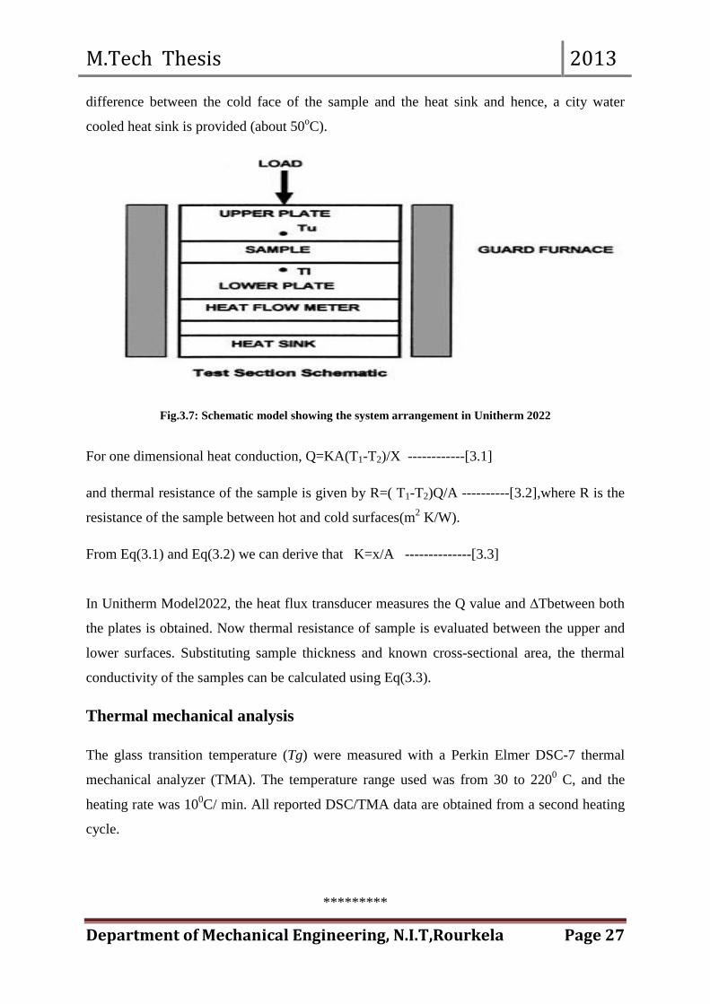
difference between the cold face of the sample and the heat sink and hence, a city water
cooled heat sink is provided (about 50oC).
Fig.3.7: Schematic model showing the system arrangement in Unitherm 2022
For one dimensional heat conduction, Q=KA(T1-T2)/X ------------[3.1]
and thermal resistance of the sample is given by R=( T1-T2)Q/A ----------[3.2],where R is the
resistance of the sample between hot and cold surfaces(m2 K/W).
From Eq(3.1) and Eq(3.2) we can derive that K=x/A --------------[3.3]
In Unitherm Model2022, the heat flux transducer measures the Q value and ∆Tbetween both
the plates is obtained. Now thermal resistance of sample is evaluated between the upper and
lower surfaces. Substituting sample thickness and known cross-sectional area, the thermal
conductivity of the samples can be calculated using Eq(3.3).
Thermal mechanical analysis
The glass transition temperature (Tg) were measured with a Perkin Elmer DSC-7 thermal
mechanical analyzer (TMA). The temperature range used was from 30 to 2200 C, and the
heating rate was 100C/ min. All reported DSC/TMA data are obtained from a second heating
cycle.
*********

M.Tech Thesis 2013
Department of Mechanical Engineering, N.I.T,Rourkela Page 28
CHAPTER 4
PHYSICAL CHARACTERIZATION OF EPOXY/Al2O3 COMPOSITES Density and void fraction: The theoretical density of composite materials in terms of weight fraction can easily be
obtained as for the following equations given by Agarwaland Broutman [64].
ρct =1/ {wm/ρm + wf/ ρf} (4.1)
wf = ρf * vf/ { ρf * vf + ρm * vm} (4.2)
Where, W and ρ represent the weight fraction and density respectively. The suffix f, m and ct
stand for the fiber, matrix and the composite materials respectively.
In case of hybrid composites, consisting of three components namely matrix, fiber and
particulate filler, the modified form of the expression for the density of the composite can be
written as:
ρct =1/ {wm/ρm + wf/ ρf + wp/ ρp } (4.3)
Where the suffix p’indicates the particulate filler materials.
Table 4.1: Density of Composites
SL
NO.
VOLUME
FRACTION
(%)
WEIGHT
FRACTION
(%)
THEORETCAL
DENSITY
MEASURED
DENSITY
POROSITY (%)
1 2.5 8.289 1.169 1.156 1.112
2 5 15.64 1.239 1.226 1.049
3 7.5 22.248 1.309 1.292 1.299
4 10 28.128 1.379 1.361 1.305
5 12.5 33.224 1.445 1.41 2.422
6 15 38.233 1.516 1.48 2.375
7 17.5 42.801 1.588 1.554 2.141
8 20 46.86 1.658 1.618 2.413
9 22.5 50.693 1.728 1.676 3.009
10 25 54.524 1.797 1.732 3.617

M.Tech Thesis 2013
Department of Mechanical Engineering, N.I.T,Rourkela Page 29
The actual density (ῤcc)of the composite, however, can be determined experimentally
by simple water immersion technique. The volume fraction of voids/porosity in the
composites is calculated using the following equation:
Porosity/voids= {ρct - ρcc }/ ρct (4.4)
The theoretical and measured densities along with the corresponding volume fraction of voids
were presented in Table 4.1. It may be noted that the composite density values calculated
theoretically from weight fractions using Eq(4.1) were not in agreement with the
experimentally determined values. The difference was a measure of voids and pores present
in the composites. It was clear from the Table 4.1 that with the addition of filler materials
more voids were found in the composites. As the filler content changes from composites to
composites the volume fraction of voids was also found to be change.
Fig 4.1: Measured and Theoretical Densities for Al2O3/epoxy composites.
A comparison of measured and theoretical density values is represented on fig 4.1 for Al2O3/epoxy composites with different filler volume fractions. Density of a composite depends on the relative proportion of matrix and reinforcing materials and this was one of the most important factors determining the properties of the composites. The void/porosity content was the cause for the difference between the values of true density and the theoretically calculated one. The voids significantly affect some of the mechanical properties and even the performance of composites in the place of use. Higher void contents usually mean lower fatigue resistance, greater susceptibility to water penetration and weathering. The knowledge of void content was desirable for estimation of the quality of the composites. It was understandable that a good composite should have fewer voids. However, presence of void was unavoidable in composite making particularly through hand-lay-up route.
1
1.1
1.2
1.3
1.4
1.5
1.6
1.7
1.8
1.9
2.5 5 7.5 10 12.5 15 17.5 20 22.5 25
Den
sity
(gm
/cc)
Volume fraction (%)
Theoretical densityMeasured density

M.Tech Thesis 2013
Department of Mechanical Engineering, N.I.T,Rourkela Page 30
SEM Analysis:-
Fig.4.2 (a)-(d): Typical SEM images of fracture surface of the composite
a b
c d

M.Tech Thesis 2013
Department of Mechanical Engineering, N.I.T,Rourkela Page 31
It is well known that the properties of the composites are strongly dependent on the
interaction of the filler and polymer. In order to evaluate this interaction, the microstructure
of the composites, including the dispersion of Al2O3 fillers into epoxy matrix was observed
by SEM. Fig. 4.2 shows the typical SEM images. The microstructures reflect particle
dispersion in the entire epoxy matrix composite.Fig.4.2a and b shows lots of
Al2O3microparticles having spherical geometry. This has been clearly observed when the
magnification of the images was improved. Furthermore, the interlayers of composites are
clearly depicted in fig.4.2c and d indicating that the epoxy molecules were strongly bonded
with Al2O3 micro balls and a few gaps were observed around these micro balls. With an
increase in the Al2O3 content, denser composites were obtained. Such mutual contact of
Al2O3 particles forms a thermal conductive pathway that heightens the thermal conductivity
of epoxy/Al2O3 composites.WithAl2O3particlesdispersed uniformly in the whole epoxy
matrix, resembles good homogeneity of the mechanical properties of the composites.
******************

M.Tech Thesis 2013
Department of Mechanical Engineering, N.I.T,Rourkela Page 32
CHAPTER 5
RESULTS AND DISCUSSION To predict the effective thermal conductivity of composite materials, several theoretical and
empirical models have been proposed in the past. Thermal conductivities for low filler
concentrations are predicted very well using this models but when there is an increase in filler
concentrations, conductive chains arises and particle agglomeration becomes large which
makes difficult to evaluate effective thermal conductivity using above model.
The theoretical analysis of heat transfer in composite material is based on the following
assumption:
(a) Locally both the matrix and fillers are homogeneous and isotropic.
(b) The thermal contact resistance between the fillers and the matrix is negligible and the
composite lamina is free from voids.
(c) The temperature distribution along the direction of heat flow is linear.
A theoretical model [63] for one dimensional heat conduction through such a
composite system has been developed using the law of minimal thermal resistance and equal
law of the specific equivalent thermal by putting the expression of all the thermal resistance
into the effective thermal conductivity model and deduced as
(5.1)
WhereΦf represents the volume fraction ,kf is the thermal conductivity of filler, kp is the
thermal conductivity of polymer matrix.
PART A: Experimental Determination of Keff and comparison with Theoretical value
The effective thermal conductivity of filled polymer composites depends not only on the
component properties and the filler content, but also on the filler shape, filler distribution, and
interaction between the filler particles.The phenomenon involving the change in the
dispersion state of the conducting phase is known as percolation. Percolation deals with the
effects of varying the connectivity of elements (e.g., particles, sites, or bonds) on random
( )
−
+
+
−
=
pff
fp
f
pp
eff
kkkkk
k
ππφ
φπ
πφ
292
34
4611
1
31
32
31

M.Tech Thesis 2013
Department of Mechanical Engineering, N.I.T,Rourkela Page 33
system i.e. long-range connectivity. According to the experimentally determined effective
thermal conductivity of composites, the Keffincreases rapidly when the filler volume fraction
reaches 16-22vol% as shown in the fig 5.1. Furthermore, the effective thermal conductivity is
reinforced nonlinearly with the increase of the filler content due to the gradual development
of the density of the network. Below the percolation threshold, the conductivity is negligible
and the threshold conductivity of the composites is equal to the polymer conductivity or
slightly higher.
Table5.1: Determination of experimental values (Keff) for different filler concentrations
SL NO
VOLUME FRACTION (%)
EXERIMENTAL VALUE (W/m-K)
THEORETICAL VALUE (W/m-K)
1 1.4 0.449 0.493
2 2.75 0.492 0.549
3 5.35 0.588 0.643
4 6.6 0.612 0.686
5 7.82 0.639 0.727
6 10.8 0.740 0.832
7 13.2 0.836 0.922
8 15.9 0.927 1.029 9 18.8 1.815 1.159 10 22.1 1.973 1.332
Fig.5.1: Thermal Conductivity of Al2O3 filled epoxy composites
0
0.5
1
1.5
2
2.5
1.4 2.75 5.35 6.6 7.82 10.8 13.2 15.9 18.8 22.1
Volume Fraction(%)
Therm
al Co
nduc
tivity
(W/m
-K)
Percolation Threshold

M.Tech Thesis 2013
Department of Mechanical Engineering, N.I.T,Rourkela Page 34
Fig5.2: Comparison of Keff values for Al2O3 filled epoxy composites Using the deduced correlation given by Eqn. (5.1), the effective thermal conductivities (Keff)
of all the composites are calculated. Fig.5.2 also presents a comparison of the calculated
values with the experimentally measured ones. The 2D and 3D finite element models of filled
polymer composites [65-66] cannot reflect the actual microscopic irregularities of the filler
shape and distribution, especially for the case of high filler content when a continuous
network of filler is formed. It is seen that the results obtained from the proposed correlation
are in good agreement with experimental results up to a filler concentration of about 16vol%.
The Al2O3 particles show a percolation behavior at this volume fraction (16vol %) at which a
sudden jump in the thermal conductivity is noticed. This is the critical concentration at which
Al2O3 particles start contacting with each other and hence the actual size of the agglomerates
becomes larger. Consequently, the heat conduction performance of epoxy composites
incorporating Al2O3 exceeds expectations.
PART B: Numerical Analysis: Concept of Finite Element Method and ANSYS
The finite element method (FEM), originally introduced by Turner et al. [67], is a powerful
computational technique for approximate solutions to a variety of ‘‘real-world” engineering
problems having complex domains subjected to general boundary conditions.
The Finite Element Analysis (FEA) is a numerical method useful for solving problems with
complicated geometries, loadings, and material properties where analytical solutions cannot

M.Tech Thesis 2013
Department of Mechanical Engineering, N.I.T,Rourkela Page 35
be obtained. The finite element method (FEM) technique helps to obtain approximate
solutions of partial differential equations. One technique is based on eliminating the
differential equation completely and work with a minimization problem. Advantages:
Flexibility with respect to boundary conditions and geometries and easy to incorporate
adequate spatial resolution by varying the element size manually or adaptively.
The goal of numerical simulation is to make predictions concerning the response of physical
systems to various kinds of excitation and, based on those predictions, make informed
decisions. Therefore mathematical models are defined and finally numerical solutions are
calculated. Mathematical models should be understood to be idealized representations of
reality and should never be confused with the physical reality that they are supposed to
represent. Through conceptualization process a mathematical model is formulated. By
discretization process, exact solution of the mathematical model is approximated and by
extraction process genuine data’s are computed from the approximate solution.
The finite element method (FEM) is a powerful tool used in numerical methods to calculate
approximate solutions to mathematical problems so that it can simulate the responses of
physical systems to various forms of excitation. It can be widely used in engineering and
science, such as elasticity, heat transfer, fluid dynamics, electromagnetism, acoustics,
biomechanics, etc. In FEM, the domain is decomposed into a finite number of sub-domains
(elements) and exact approximate solution is obtained by the variational or weighted residual
methods. ANSYS is general-purpose finite element modelling package used to solve
numerous mechanical problems involving static/dynamic, structural analysis (both linear and
nonlinear), heat transfer, fluid problems, as well as acoustic and electromagnetic problems. In
finite element solution of engineering problems the main tasks of mesh generation,
processing (calculations) and graphical representation of results are usually assigned to
independent computer programs. These programs can either be embedded under a common
shell (or interface) to enable the user to interact with all three parts in a single environment or
they can be implemented as separate sections of a software package. Development and
organization of graphics programs requires expertise in areas of computer science and
software designs which outside the scope of text dealing with finite element techniques.
With finite-element program ANSYS, thermal conductivity analysis is carried out through the
prepared composite body. A three-dimensional physical model with spheres-in-a-cube lattice
array have been used to simulate the microstructure of composite materials for six different

M.Tech Thesis 2013
Department of Mechanical Engineering, N.I.T,Rourkela Page 36
filler concentrations varying from 1vol% to 12 vol% and corresponding effective thermal
conductivities of these composites are determined using ANSYS.
Steps involved in FEM:-
1. Defining the problem.
2. Selection of field variables and elements.
3. Modelling.
4. Discretize the elements (Meshing).
5. Apply boundary conditions.
6. Solve the system of equations to get nodal unknowns.
7. Post-processing of solution to get required values.
Description of the problem:-
The determination of effective properties of composite materials is of paramount importance
for functional design and application of composite materials. Microstructure represents shape,
size distribution, spatial distribution and orientation distribution of the reinforcing inclusion
in the matrix. The effect of microstructure on the effective properties can be gained from the
investigation of composites with periodic structure.
For numerical analysis, the temperatures at the nodes along the surfaces ABCD is given as T1
(=1000C) and the convective heat transfer coefficient is given as 2.5 W/m2K at ambient
temperature of 270C. The heat flow is unidirectional with suitable boundary conditions are
shown in Fig.5.3. The rest surfaces parallel to the direction of the heat flow are assumed heat
flux to be zero. The temperatures at the nodes in the interior region and on the adiabatic
boundaries are obtained with ANSYS programming.

M.Tech Thesis 2013
Department of Mechanical Engineering, N.I.T,Rourkela Page 37
Fig.5.3: Boundary Conditions
Assumptions
The numerical analysis is based on the following assumptions:
1. The composites are macroscopically homogeneous.
2. Locally both the matrix and filler are homogeneous and isotropic.
3. The thermal contact resistance between the filler and the matrix is negligible.
4. The composite lamina is free of voids.
5. The problem is based on 3D physical model.
6. The filler are arranged in a square periodic array/uniformly distributed in matrix.
Table 5.2: Effective thermal conductivities obtained from different models and experimentation
Filler
Content
(Vol %)
Effective thermal conductivity of composites Keff(W/m-K)
Rule of mixture
Geometric mean model
Maxwell’s
equation
Bruggeman’s
model
Lewis and
Nielsen’s equation
Proposed model
FEM simulation
value
Experimental
value
0 0.363 0.363 0.363 0.363 0.363 0.363 0.363 0.363
1.41 0.368 0.387 0.378 0.378 0.375 0.481 0.393 0.449
3.35 0.375 0.423 0.399 0.401 0.394 0.548 0.435 0.521
5.23 0.383 0.461 0.421 0.425 0.414 0.607 0.484 0.579
7.85 0.394 0.519 0.452 0.461 0.443 0.687 0.542 0.640
9.42 0.403 0.558 0.472 0.483 0.462 0.735 0.607 0.703
11.3 0.409 0.608 0.497 0.514 0.487 0.795 0.654 0.763

M.Tech Thesis 2013
Department of Mechanical Engineering, N.I.T,Rourkela Page 38
The effective thermal conductivity values of the particulate filled epoxy composites with varied proportions of alumina particulates obtained using Maxwell’s correlation, ROM model, Lewis-Nielson Model and those obtained from FEM analysis are presented in Table5.2. It elaborates a brief comparison among the results obtained using these models with regard to the values of effective conductivity obtained experimentally.
Temperature Profiles of Composite from FEM Analysis:- The temperature profiles obtained from FEM analysis for the composites with particulate
concentrations of 1.4, 3.35, 5.23, 7.85, 9.04 and 11.3 vol. % are presented in Fig.5.4 (a-f)
respectively.
Fig 5.4(a): Temperature profiles for composite of filler concentration 1.42 vol %
Fig 5.4(b): Temperature profiles for composite of filler concentration 3.35 vol %

M.Tech Thesis 2013
Department of Mechanical Engineering, N.I.T,Rourkela Page 39
Fig 5.4(c): Temperature profiles for composite of filler concentration 5.23 vol %
Fig 5.4(d): Temperature profiles for composite of filler concentration 7.85 vol %

M.Tech Thesis 2013
Department of Mechanical Engineering, N.I.T,Rourkela Page 40
Fig 5.4(e): Temperature profiles for composite of filler concentration 9.4 vol %
Fig 5.4(f): Temperature profiles for composite of filler concentration 11.3 vol %

M.Tech Thesis 2013
Department of Mechanical Engineering, N.I.T,Rourkela Page 41
The determination of effective properties of composite materials is of paramount importance
for functional design and application of composite materials. One of the important factors
that influence the effective properties and can be controlled to an appreciable extent is the
microstructure of the composite. Here, microstructure means the shape, size distribution,
spatial distribution and orientation distribution of the reinforcing inclusion in the matrix.
Increase in filler concentrations attributes to the formation of continuous chains or network of
conducting phase that spans through the insulating matrix. When the probability of the
particles being in contact become large, highly conductive particles produce a path of low
resistance for heat to flow and this would contribute to an increase in effective conductivity.
Due to spherical nature of micro-sized alumina particles, the stress concentration effect is
reduced which increases the contact between the particles resultingan increaseinKeffof system.
Table 5.3: Percentage error of different models with experimental values
Filler
Content
(Vol %)
% of errors with experimental values
Rule of
Mixture
Geometric mean model
Maxwell’s
equation
Bruggeman’s
model
Lewis and
Nielsen’s
equation
Proposed model
1.4 18.04 13.8 15.8 15.8 16.5 6.7 3.35 28.02 18.8 23.42 23.03 24.4 4.9 5.23 33.85 20.38 27.3 26.6 28.5 4.6 7.85 38.44 18.9 29.4 27.9 30.8 6.8 9.4 42.67 20.63 32.9 31.3 34.3 4.4
11.3 46.39 20.31 34.9 32.6 36.2 4.0
Table 5.4: Percentage error of FEM Analysis with experimental values
Sample
Volume (%) Weight (%) FEM (% errors)
1 1.4 4.78 12.4
2 3.35 10.91 16.5
3 5.23 16.345 16.4
4 7.85 23.15 15.3
5 9.4 26.84 13.7
6 11.3 31.05 14.3

M.Tech Thesis 2013
Department of Mechanical Engineering, N.I.T,Rourkela Page 42
Fig 5.5: Comparison of values of Kefffor different theoretical models and FEM
It can be seen from the fig.5.5 that the Keffincreases non-linearly with increase in volume
fraction of filler particles which agglomerates the neighbouring particles while for low filler
concentrations there is low dispersion of particles in the matrix. Figure 5.5 clearly
demonstrates that although the thermal conductivity of a composite increase with the increase
of the filler content in the whole range of the filler content, the sensitivity of the thermal
conductivity to the filler content is dependent on the filler content in the composite. The
reason leading to this outcome is that for the composite with low filler loading, most filler
powders are surrounded by the matrix and separated with each other which mean the
channels for thermal conduction is mainly made up of the matrix but not fillers; in other
words, the thermal conductivity of the composite is mainly dependent on the matrix.
Therefore, in this situation, the thermal conductivity of the composite increases slowly with
the increase of the filler content. Since heat tends to flow through the fillers just as electric
current where electric resistance is low, the thermal conduction of fillers makes major
contribution to the value of the thermal conductivity of the composites. Well-dispersed fillers
are easy to become the component of the conductive channels; in addition, improved
interface tends to increase the thermal conductivity by minimizing the phonon scattering at
0.1
0.2
0.3
0.4
0.5
0.6
0.7
0.8
0.9
0 1.41 3.35 5.23 7.85 9.42 11.3
Filler content (vol%)
Ther
mal
cond
uctiv
ity (W
/m-K
)Rule of mixture
Geometric Mean
Maxw ell model
Bruggeman's model
L-N model
Proposed model
FEM
Experimental value

M.Tech Thesis 2013
Department of Mechanical Engineering, N.I.T,Rourkela Page 43
the interface. In case of the composite with higher filler content, the effect associating the
surface treatment of filler enhances because there are more interfaces in the composite.
Fig.5.6: Comparison of Keff using proposed, experimental and FEM values
The values obtained from theoretical models are quite low compared to the measured values,
but variation of the theoretical estimation by proposed model of the effective thermal
conductivity are well within the range of experimental measured values as shown in fig.5.6.
A variation of about 7-8% is observed between the experimental and proposed model values
which accounts to the assumptions taken while deriving the equation for the proposed model.
The equation is derived on the basis of micro-spherical alumina particulates being uniformly
distributed in the polymer matrix, but practically in a fabricated composite uniform
distribution of particles is not possible as they are dispersed randomly. Also, it is assumed
that heat flow is unidirectional which, in actual practice it is impossible to restrict the heat
flow in one direction.
The simulated values of effective thermal conductivity of the composites obtained from FEA
are presented in Table 5.2along with the corresponding measured values for different samples
with filler concentration varying from 0vol% to 11.3vol%. Table 5.3 & 5.4 shows percentage
errors established between thermal conductivity model values and proposed model values
with the experimental values respectively. It is noticed that Keffobtained from the proposed
model are quite in agreement with experimental values than the FEM values, even though
0.1
0.2
0.3
0.4
0.5
0.6
0.7
0.8
0.9
0 1.41 3.35 5.23 7.85 9.42 11.3
Filler content (vol%)
Therm
al co
nduc
tivity
(W/m
-K)
Proposed modelExperimental valueFEM

M.Tech Thesis 2013
Department of Mechanical Engineering, N.I.T,Rourkela Page 44
theerrors associated with sphere-in-cube simulations lies in the 0-17% which is quite
reasonable. However, it leads to conclusion that for a particulate filled composite of this kind
the FEM can be gainfully employed as a predictive tool in determining the effective thermal
conductivity for a wide range of particle concentration. The difference between the simulated
values and the measured value of conductivity may be attributed to the fact that some of the
assumptions taken for the numerical analysis are not real, as in the fabricated composite
sample, the fillers are actually dispersed in the resin almost randomly. With addition of 1.4
vol. % of Al2O3, the thermal conductivity increases by about 8.6 % and with addition of 11.3
vol.% of Al2O3, the thermal conductivity increases by about 40% when compared with neat
epoxy resin. It might be that the aluminium oxide particles produce heat transfer links in the
matrix due to the small distance between neighbouring particles in the case of high
concentration and thus, the conductive capacity of the composite system is quickly enhanced.

M.Tech Thesis 2013
Department of Mechanical Engineering, N.I.T,Rourkela Page 45
CHAPTER 6
SUMMARY and CONCLUSION Thesis Summary As mentioned earlier, the continuing miniaturization of electronic devices and the increasing
power output of electrical equipment have created new challenges in packaging and
insulating materials. Dissipating adequate amount of heat from electronic devices is essential,
otherwise, accumulated heat induces thermal fatigue that costs service life and operation
efficiency. The key goals are to develop materials with high thermal conductivity, low
coefficient of thermal expansion (CTE), low dielectric constant, high electrical resistivity,
high breakdown strength, and most importantly, low cost. Polymeric materials have attracted
increasing interest because of their excellent process ability and low cost; however, most
polymers are thermally insulating and have a thermal conductivity between 0.1 and 0.5 W/m-
K.Such thermal issues can be elevated using thermally conductive and electrically insulating
ceramic fillers like aluminium nitride, aluminium oxide, silicon carbide and boron nitride
doped in PMCs.
The research presented in this thesis consists of three parts:
The first part describes the detailed fabrication of epoxy based composites filled with
micro-sized aluminium oxide (Al2O3) particles in different volume proportions by
hand lay-up technique.
The second part provides information about physical characterization of the prepared
composites which include comparison of theoretical and measured density. A SEM
analysis is done to study the morphological structure of filled polymer composites.
The third part includes an assessment of the effective thermal conductivity of these
composites using finite element method followed by their validation with
experimental calculated values and a brief comparison is done with developed
theoretical model and existing thermal conductivity models proposed by the authors.
Besides, thermal mechanical analysis is carried out that includes effect of filler
content on Tg of composites and CTE simultaneously.

M.Tech Thesis 2013
Department of Mechanical Engineering, N.I.T,Rourkela Page 46
Conclusions
The numerical and experimental investigation on thermal conductivity of alumina particulates filled epoxy composites has led to specific conclusions:
The addition of conductive fillers in the polymer matrix is an effective way to increase thermal conductivity of polymers for several industrial applications. To make adequate use of the filled polymer composites especially in printed circuit boards and micro-electronics applications, experimental results are necessary for the specific type of composite in question.
Successful fabrication of epoxy composites filled Al2O3 particles by hand lay-up technique is possible.
Finite element method (FEM) can be gainfully employed for determination of effective thermal conductivity of these composites with different amount of Al2O3content.
Incorporation of micro-sized Al2O3 results in significant increase of thermal conductivity of pure epoxy resin and there by enhances its conduction capability. In comparison to neat epoxy resin, the thermal conductivity increases by about 40 % with addition of 11.3 vol% of Al2O3 from FEM analysis and around an increase of 80% with addition of 22.1 vol% of Al2O3 from experimental analysis.
Higher percentage of Al2O3 will achieve more improved thermal conductivity and a rapid increase in thermal conductivity with increase in filler content is observed.
Increase in Al2O3content in epoxy results in increase in the glass transition temperature and decrease in the value of CTE, hence providing a wider application range and superior thermal stability.
With increased thermal conductivity, this new class of Al2O3filled epoxy
composites can be used for applications such as electronic packages, encapsulations, printed circuit boards.
Scope for future work This work leaves a wide scope for future investigators to explore many other aspects of thermal behaviour of particulate filled composites. Some recommendations for future research include: Effect of filler shape and size on thermal properties of the composites
Exploration of new fillers and polymers for development of materials having high thermal conductivity and low electrical conductivity.

M.Tech Thesis 2013
Department of Mechanical Engineering, N.I.T,Rourkela Page 47
REFERENCES [1] R. R Tummala and E. J. Rymaszewski , Microelectronic Packaging Handbook, New
York,VanNostrand Reinhold, (1989)523–658.
[2] W.Kim, J. W. Bae, I. D. Choi, and Y. S. Kim, Thermally Conductive EMC for Microelectronic Encapsulation, Polym. Eng. Sci., 39 [4] (1999) 756–766.
[3] Eun-Sung Lee, Sang-Mock Lee, Daniel J. Shanefield and W.Roger Cannon, Enhanced Thermal Conductivity of Polymer Matrix Composite Via High Solids Loading of Aluminium Nitride in Epoxy Resin, J. Am. Ceram. Soc.,91[4] (2008) 1169-1174.
[4] YunshengXu, D.D.L. Chung and Cathleen Mroz , Thermally conducting aluminium nitride polymer-matrix composites, Composites Part A,32(2001)1749-1757.
[5] X. Jung, G. Xu, Thermally conductive polymer composites for electronic packaging,
Journal of Applied Polymer Science .65, 2733-8, 1997.
[6] S.Nikkeshi, M.Kudo, T.Masuko, J.Appl.Polym.Sci.69 (1998) 2593-2598. [7] N.S. Saxena, N.S. PradeepSaxena, P. Pradeep, G., Mathew, S. Thomas, M. Gustafsson
and S.E. Gustafsson, Thermal Conductivity of Styrene Butadiene Rubber Compounds with Natural Rubber Prophylactics Waste as Filler, Eur. Polym. J., 35(9) (1999) 1687–1693.
[8] H. Ishida and S. Rimdusit, Very High Thermal Conductivity Obtained by Boron Nitride-filled Polybenzoxazine, Thermochim.Acta, 320(1–2) (1998) 177–186.
[9] A. Bjorneklett, L. Halbo, and H. Kristiansen, Thermal Conductivity of Epoxy Adhesives Filled with Silver Particles, Int. J. Adhes. Adhes. , 12(2) (1992) 99–104.
[10] Y. Agari, A. Ueda, M. Tanaka and S. Nagai, Thermal Conductivity of a Polymer Filled
with Particles in the Wide Range from Low to Super-high Volume Content, J. of Appl. Polym. Sci., 40(5–6) (1990) 929–941.
[11]D. Kumlutas, I.H. Tavman, and M.T. Coban, Thermal Conductivity of Particle Filled Polyethylene Composite Materials, Compos. Sci. Technol., 63(1) (2003) 113–117.
[12] D. Veyret, S. Cioulachtjian, L. Tadrist, and J. Pantaloni, Effective Thermal Conductivity of a Composite Material: A Numerical Approach, Transactions of the ASME- J. Heat Transfer, 115 (1993) 866–871.
[13] J.T. Mottram and R. Taylor, Thermal Conductivity of Fibre/Phenolic Resin Composites. Part II: Numerical Evaluation, Compos. Sci. Technol., 29(3) (1987) 211–232.
[14] O.O. Onyejekwe, Heat Conduction in Composite Media: A Boundary Integral Approach, Comput. Chem. Eng., 26(11) (2002) 1621–1632.
[15] I.H. Tavman, Thermal and Mechanical Properties of Aluminium Powder filled High-density Polyethylene Composites, J. Appl. Polym. Sci., 62(12) (1996) 2161–2167.
[16].N.M. Sofian, M. Rusu, R. Neagu and E. Neagu, Metal Powder-filled Polyethylene Composites. V. Thermal Properties, J. Thermoplast. Compos.Mater., 14(1) (2001) 20–33.

M.Tech Thesis 2013
Department of Mechanical Engineering, N.I.T,Rourkela Page 48
[17] H.S. Tekce, D. Kumlutas and I.H. Tavman, Determination of the Thermal Properties of Polyamide-6 (Nylon-6)/Copper Composite by Hot Disk Method, In: Proceedings of the 10th Denizli Material Symposium, (2004) 296–304.
[18]R.C. Progelhof, J.L. Throne & R.R. Ruetsch, Methods of Predicting the Thermal
Conductivity of Composite Systems.Journal of Polymer Engg and Science,16 (9), 615– 625, 1976
[19]Y.P. Mamunya, V.V. Davydenko, P. Pissis, E.V. Lebedev, Electrical and Thermal Conductivity of Polymers Filled with Metal Powders, Journal of European Polymer, 38 (9), 1887–1897, 2002
[20]P. Procter, J. Solc, Improved thermal conductivity in microelectronic encapsulants, IEEE T ComponHybr, 14(4) (1991) 708–713
[21]Y. Nagai, G.C. Lai, Thermal conductivity of epoxy resin filled with particulate aluminium nitride powder, J. Ceram. Soc. Jpn., 105(3) (1997) 197–200.
[22] B. Weidenfeller, M. Höfer, F.R. Schilling, J. Compos. Part A: Appl. Sci. Manuf. 35 (4)
(2004) 423–429.
[23] S.W. Gregory, K.D. Freudenberg, P. Bhimaraj and L. S Schadler, A study on the friction and wear behavior of PTFE filled with alumina nanoparticles, J. Wear, 254 (2003) 573–580.
[24] K. Jung-il, P.H. Kang and Y.C. Nho, Positive temperature coefficient behavior of polymer composites having a high melting temperature, J. Appl. Polym. Sci., 92 (2004) 394–401.
[25] S. Nikkeshi, M. Kudo and T. Masuko, Dynamic viscoelastic properties and thermal properties of powder-epoxy resin composites, J. Appl. Polym. Sci., 69 (1998) 2593-2598.
[26] R.N. Rothon, Mineral fillers in thermoplastics: filler manufacture, J. Adhes., 64 (1997)
87–109. [27] R.N. Rothon, Mineral fillers in thermoplastics: filler manufacture and characterization,
Adv. Polym. Sci. ,139(1999) 67–107. [28]L.E. Nielsen and R.F. Landel, Mechanical properties of polymers and composites.second
ed., Marcel Deckker, New York, (1994) 377–459. [29] S.T. Peters, Handbook of composites, second ed., Chapman and Hall, London, (1998)
242–243. [30] R.J. Young and P.W.R. Beaumont, Failure of brittle polymers by slow crack growth Part
3 Effect of composition upon the fracture of silica particle-filled epoxy resin composites, Mater. Sci. , 12(4) (1977) 684–692.
[31]A.J. Kinoch, D.L. Maxwell and R.J. Young, The fracture of hybrid particulate composites, Mater. Sci., 20 (1985) 4169–4184.
[32] R. Young, D.L. Maxwell and A.J. Kinloch, The deformation of hybrid particulate composites, Mater. Sci., 21 (1986) 380–388.

M.Tech Thesis 2013
Department of Mechanical Engineering, N.I.T,Rourkela Page 49
[33] S.W. Koh, J.K. Kim and Y.W. Mai, Fracture toughness and failure mechanisms in silica-filled epoxy resin composites: effects of temperature and loading rate, Polymer , 34(16) (1993) 3446–3455.
[34] W.J. Cantwell and A.C. Moloney, Fractography and failure mechanisms of polymers and composites, Elesvier, Amsterdam (1994) 233.
[35] M. Imanaka, Y. Takeuchi, Y. Nakamura, A. Nishimura and T. Lida, Fracture toughness of spherical silica-filled epoxy adhesives, Int. J. Adhes. Adhes. , 21 (2001) 389–396.
[36] H. Wang, Y. Bai, S. Lui, J. Wu and C.P. Wong, Combined effects of silica filler and its interface in epoxy resin, Acta Mater., 50 (2002) 4369–4377.
[37] I.Yamamoto, T. Higashihara and T. Kobayashi, Effect of silica-particle characteristics
on impact/usual fatigue properties and evaluation of mechanical characteristics of silica-particle epoxy resins, JSME Int. J., 46 (2) (2003) 145–153.
[38] Y. Nakamura, M. Yamaguchi, A. Kitayama, M. Okubo and T. Matsumoto, Effect of particle size on fracture toughness of epoxy resin filled with angular-shaped silica, Polymer, 32(12) (1991) 2221–2229.
[39] Y. Nakamura, M. Yamaguchi, M. Okubo and T. Matsumoto, Effect of particle size on impact properties of epoxy resin filled with angular shaped silica particles, Polymer, 32(16) (1991) 2976–2979.
[40] Y. Nakamura, M. Yamaguchi, M. Okubo and T. Matsumoto, Effects of particle size on mechanical and impact properties of epoxy resin filled with spherical silica, J. Appl. Polym. Sci., 45 (1992) 1281–1289.
[41] Patnaik Amar, Md. Abdulla, SatapathyAlok, B. Sandhyarani and K. S. Bhabani, A study
on a possible correlation between thermal conductivity and wear resistance of particulate filled polymer composites, Mater.Des.,(In press) (2009).
[42] Nayak. R, Alok, S., Tarkes, D, A computational and experimental investigation on
thermal conductivity of particle reinforced epoxy composites, Journal of Computational Material Sc.48, 576-581, 2010
[43]R. FHill and P. H. Supancic Thermal Conductivity of Platelet-Filled Polymer Composites. Journal of the American Ceramic Society, 4 (2004) 851-857.
[44] Perminov, V.P., Modyanova, A.G., Ryabkov, Yu.I.,Sevbo, O.A., Gailyunas, I.A., and
Kuchin, A.V., EpoxyComposites Modified with Finely Dispersed Fillers, Zh.Prikl. Khim., (S.-Peterburg), 2002, vol. 75, no. 4pp.650–654 [Russ. J. Appl. Chem.(Engl. transl.), 2002,vol. 75, no. 4, pp. 636–640].
[45] S. Ma, I. Gibson , G. Balaji , Q.J. Hua, Development of epoxy matrix composites for
rapid tooling applications, Journal of Materials Processing Technology 192–193 (2007) 75–82.
[46] S.Biswas, A.Satapathy, A study on Tribological Behaviour of Alumina filled Glass Epoxy composites using Taguchi Experimental Design, Tribology Transactions, vol.53, 520-532(2010)

M.Tech Thesis 2013
Department of Mechanical Engineering, N.I.T,Rourkela Page 50
[47] A.Pattnaik, A.Satapathy, S.Biswas, Investigations on Three body Abrasive wear and Mechanical properties of Particulate filled Glass epoxy composites, Malaysian Polymer Journal,vol.5(2), p.37-48(2010)
[48] K.Sabeel Ahmed, S.S.Khalid, V.Mallinatha, S.J.AmithKumar, Dry Sliding wear behaviour of SiC/Al2O3 filled jute/epoxy composites, J. Materials and Design, 36, 306-315(2012)
[49] Osman Asi, An experimental study on the bearing strength behaviour of Al2O3 particle filled Glass fiber reinforced composites pinned joints, J. Composite Structures, 92, 354-363(2010)
[50] Y.Wang, S.Lim, J.L.Luo, Z.H.Xu, Tribological and Corrosion behaviours of Al2O3 /polymer nanocomposite coatings, J. of Wear, 260, 976-983(2006)
[51] B. N. Dudkin, G. G. Zainullin, P. V. Krivoshapkin, E. F. Krivoshapkina, and M. A. Ryazanov, Influence of Nanoparticles and Nanofibers of AluminumOxideon the Properties of Epoxy Composites, Glass Physics and Chemistry, Vol. 34, No. 2, pp. 187–191(2008)
[52]L.Sim, S. R. Ramanan, H.Ismail, K. N. Seetharamu and T. Goh, Thermal characterization of Al2O3 and ZnO reinforced silicone rubber as thermal pads for heat dissipation purposes, Thermochim. Acta , 430(2005)155–165.
[53] D.C. Moreira , L.A. Sphaier , J.M.L. Reis, L.C.S. Nunes, Experimental investigation of
heat conduction in polyester–Al2O3and polyester–CuOnanocomposites, International J. of Experimental Thermal and Fluid Science, 35(2011), 1458-1462
[54] T.N.G. Tsao, Thermal Conductivity of Two Phase Materials, J. Ind. Eng. Chem , 53(5)
(1961) 395–397.
[55]S.C. Cheng and R.I. Vachon, The Prediction of the Thermal Conductivity of Two and Three Phase Solid Heterogeneous Mixtures, Int. J. of Heat Mass Transfer, 12(3) (1969) 249–264 .
[56] Y. Agari and T. Uno, Estimation on Thermal Conductivities of Filled Polymers, J. Appl.
Polym. Sci., 32(7) (1986) 5705–5712. [57] J. Maxwell, Electricity and Magnetism, Oxford, Clarendon, 1873.
[58] T. Lewis and L.Nielsen , Dynamic mechanical properties of particulate-filled polymers, J. Appl. Polym. Sci. , 14 ( 1970),1449-1471.
[59] J.C. Halpin ,Stiffness and expansion estimates for oriented short fiber composites, J. .
Compos.Mater. , 3(1969), 732–734.
[60] J. Ashton, J. Halpin, P.Petit, Primer on composite materials: analysis. Stamford: Technomic Pub. Co; 1969.
[61] M. Ohashi, S. Kawakami, Y. Yokogawa and G. C. Lai, Spherical aluminum nitride fillers for heat-conducting plastic packages, J. Am. Ceram. Soc., 88(2005), 2615–2618.

M.Tech Thesis 2013
Department of Mechanical Engineering, N.I.T,Rourkela Page 51
[62]J.Z.Liang, F.H.Li, Heat transfer in polymer composites filled with inorganic hollow micro-spheres: A theoretical model, Journal of Polymer Testing, 26(2007), 1025-1030.
[63]A. Agrawal and A. Satapathy, “Development of a theoretical model for effective thermal
conductivity of polymer filled with hybrid fillers”, Selected for International Conference on Recent Advances in Composite Materials”, Feb, 2013.
[64] Agarwal B D, Broutman L J. Analysis and performance of fibercomposites: Second
Edition. John Wiley and Sons, Inc.; 1990. [65] Tu, S.T., Cai, W.Z., Yin, Y. and Ling, X. (2005). Numerical Simulation of Saturation
Behavior of Physical Properties in Composites with Randomly Distributed Second-phase, Journal of Composite Materials, 39(7): 617_631.
[66] Cai, W.Z., Tu, S.T. and Tao, G.L. (2005). Thermal Conductivity of PTFE Composites
with Three-dimensional Randomly Distributed Fillers, Journal of Thermoplastic CompositeMaterials, 18(3): 241_253.
[67]M.J. Turner, R.W. Clough, H.C. Martin, L.J. Topp, J. Aeronaut. Sci. ,vol.23,pp. 805–
823, 1956.
[68] Y. Y.Sun, Z. Q Zhang, K. S Moon and C. P Wong, Glass transition and relaxation behavior of epoxy nanocomposites ,JPolym. Sci. Part B: Polym. Phys. , 42 ( 2004) 3849-3858.
[69] B. J. Ash, L. S.Schadler and R. W. Siegel, Glass transition behavior of
alumina/polymethylmethacrylatenanocomposites,MaterLett, 55(2002) 83–87. [70] S.Singha and M. J. Thomas, Dielectric properties of epoxy nanocomposites, IEEE T
Dielect El In, 15 ( 2008) 12-23.
********************