a study on the elongation behaviour of synthetic fibre
TRANSCRIPT

A Study on the Elongation Behaviour ofSynthetic Fibre Ropes under Cyclic Loading
Deoraj Asane, Alexander Schmitz, Yushi Wang and Shigeki Sugano
Abstract— Synthetic fibre ropes have high tensile strength,a lower friction coefficient and are more flexible than steelropes, and are therefore increasingly used in robotics. However,their characteristics are not well studied. In particular, previouswork investigated the long-term behaviour only under staticloading. In this paper, we investigate the elongation behaviourof synthetic fibre ropes under cyclic loading. In particular, weuse ropes made from Dyneema DM20 (UHMWPE) and ZylonAS (PBO), which according to prior work have low creep. WhileDyneema is more widely used, Zylon has higher tensile strength.We could show that under cyclic loading the Dyneema DM20rope elongated more than 9% and kept on extending even after500 cycles. Zylon exhibited a more stable and lower elongationof less than 3%.
I. INTRODUCTION
Tendons are a popular option for actuation in robots. Theycan be used to place the actuator apart from the actuatedjoint. For example, in multi-fingered robot hands, which havea lot of actuated joints in limited space, there is typicallynot enough space to place the motors in the fingers, and acommon solution is to place the actuators in the forearminstead and connect the actuators with tendons to the joints[1][2][3]. Even if there is enough space to place the actuatorin the link, tendons can be used to place the actuator closer tothe base of the robot, which reduces the moving mass of therobot, which has benefits for safety and reduces the requiredpower by the actuators for robotic arms [4]. Robots that try toreplicate the human musculoskeletal system also use tendons[5]. Tendons have been also used in twisted string actuators[6][7], where the tendon also acts as a form of speed reducer,or for passive gravity compensation mechanisms [8].
Steel tendons are most commonly used. However, syn-thetic fibre ropes have benefits compared to steel tendons, inparticular, they have high tensile strength (breaking strength),a lower friction coefficient (1/3 to 1/5 than that of steel ropes[9]), and high flexibility. Due to their advantages, syntheticropes are increasingly used in robots [5] [10] [11] [12] [13][14].
However, the properties of synthetic fibre ropes, especiallyof the low creep ones used in this paper, have not beenwell studied. Horigame and Endo [9] studied the repetitivebending durability of synthetic fibres. They also showed thatthe ratio of pulley diameter D and wire diameter d determinesthe strength reduction. Horigame et al. [15] studied different
This research was supported by the JSPS Grant-in-Aid No. 19H02116,No. 19H01130, the Tateishi Science and Technology Foundation ResearchGrant (S), and the Research Institute for Science and Engineering, WasedaUniversity.
The authors are with Waseda University, Tokyo, Japan. (Correspondingauthor: [email protected])
terminal fixation methods for synthetic fibre ropes. Summersinvestigated several factors relevant for robotic applications,but not the elongation of the ropes [16].
One characteristic of particular importance is the elon-gation behaviour of tendons when loaded. Compared tosteel tendons, synthetic fibre ropes exhibit substantial strainas a result of stress. Indeed, this is one of the majordownsides of synthetic fibre ropes and should be inves-tigated. Several papers studied the elongation behaviourof synthetic ropes, especially for the use as marine ropes[17][18][19][20][21][22][23]. However, the required charac-teristics of marine ropes are different from those of tendonsin robots. Werff et. al [24] studied the creep behaviour ofseveral Dyneema ropes and concluded that DM20 has lowcreep even after 6 months. Sry et. al [25] studied the effect ofimpact loading. Kirchhoff et. al [26] studied the elongationbehaviour of several ropes, with the intended use in roboticapplications. However, in none of these studies the effectof cyclic loading was investigated. For robotic applications,cyclic loading is crucial.
This paper studies the elongation behaviour under cyclicloading of two synthetic fibres, which in previous worksexhibited low creep, i.e. Dyneema DM20 and Zylon (PBO).
II. MATERIALS
In this paper, based on the related studies, we usedDyneema and Zylon, two of the most well-known syntheticfibres in robotic applications which are reported to havenegligible creep. Two ropes made from Dyneema DM20fibres and Zylon AS (As Spun) fibres are compared basedon the testing data acquired from the experiments.
Dyneema DM20 falls under the Ultra-High-Molecular-Weight-Polyethylene (UHMWPE) category of synthetic fi-bres. Dyneema DM20 fibre is available in the market in theform of ropes, sheets or only fibres and is manufacturedby various companies. As stated in the previous section,Dyneema DM20 is said to exhibit low creep. Furthermore,it has high resistance to abrasion and UV light, but alow tolerance to temperature. Different sources list differ-ent temperature limits for Dyneema, with 50◦C being thetemperature at which the material starts decomposing due totemperature alone.
Zylon is a trademarked name for a material made fromliquid-crystalline poly-phenylene benzobisoxazole (PBO) fi-bres, which has a rigid and very linear molecular structure.Compared to Dyneema, Zylon has a considerably highertolerance to high temperatures, as stated in [27]. Zylonis manufactured by Toyobo Co. LTD, Japan and is also
2020 IEEE/RSJ International Conference on Intelligent Robots and Systems (IROS)October 25-29, 2020, Las Vegas, NV, USA (Virtual)
978-1-7281-6211-9/20/$31.00 ©2020 IEEE 6326
available in the form of ropes, sheets, etc. or fibres. Liuet. al [28] also found that PBO fibre is more resistant toheat than Dyneema, but has a weak resistance to UV light.Previous work found that Zylon experiences significant lossof tensile strength during repeated bending [9]. Moreover,Zylon is somewhat stiffer than Dyneema. Specifications ofthe Dyneema fibre and the Zylon AS fibre are stated inTable I.
TABLE I: Specification of materials used.
Material Dyneema DM20 Zylon ASTensile Modulus (cN/dtex) 920 1150
Elongation at break (%) 3.6 3.5Melting Point (◦C) 150 650
Distributor DSM Toyobo Co, LTD
III. EXPERIMENTS
A. Test Samples
Ropes made from Dyneema DM20 and Zylon AS wereused in the experiments. A ∅4 mm Dyneema tendon wasselected for our experiments. The Dyneema rope that weused in the experiments was purchased from LIROS GmbH.Upon consulting with DSM technical support, the creep of∅3 mm and ∅4 mm Dyneema ropes at 30◦C and 70◦Cwith a maximum load of 2 kN was calculated using acreep prediction calculator developed by DSM. The ∅4 mmmodel showed far better resistance to creep than the ∅3 mmrope, especially at 70◦C, which is a temperature that iseasily attained in robotic actuator modules. Furthermore,ropes with diameters above 4 mm were estimated to havelesser flexibility, which was not desirable for our intendedapplication as a tendon in a robot. The Dyneema tendon hadan eye loop on both ends with splicing as the end terminalfixation technique. As advised on page 38 of [29], the splicedeye loop of the Dyneema tendon was 4 times the diameter ofthe shaft on which it was to be mounted on. The end loopsof the Dyneema tendon were spliced by Sake Robotics, USAand they also pre-stretched it with high load for a short time.
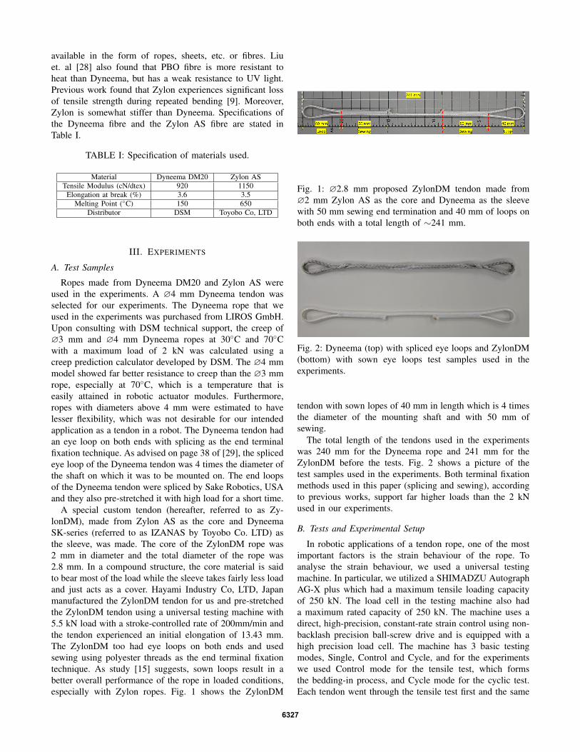
A special custom tendon (hereafter, referred to as Zy-lonDM), made from Zylon AS as the core and DyneemaSK-series (referred to as IZANAS by Toyobo Co. LTD) asthe sleeve, was made. The core of the ZylonDM rope was2 mm in diameter and the total diameter of the rope was2.8 mm. In a compound structure, the core material is saidto bear most of the load while the sleeve takes fairly less loadand just acts as a cover. Hayami Industry Co, LTD, Japanmanufactured the ZylonDM tendon for us and pre-stretchedthe ZylonDM tendon using a universal testing machine with5.5 kN load with a stroke-controlled rate of 200mm/min andthe tendon experienced an initial elongation of 13.43 mm.The ZylonDM too had eye loops on both ends and usedsewing using polyester threads as the end terminal fixationtechnique. As study [15] suggests, sown loops result in abetter overall performance of the rope in loaded conditions,especially with Zylon ropes. Fig. 1 shows the ZylonDM
Fig. 1: ∅2.8 mm proposed ZylonDM tendon made from∅2 mm Zylon AS as the core and Dyneema as the sleevewith 50 mm sewing end termination and 40 mm of loops onboth ends with a total length of ∼241 mm.
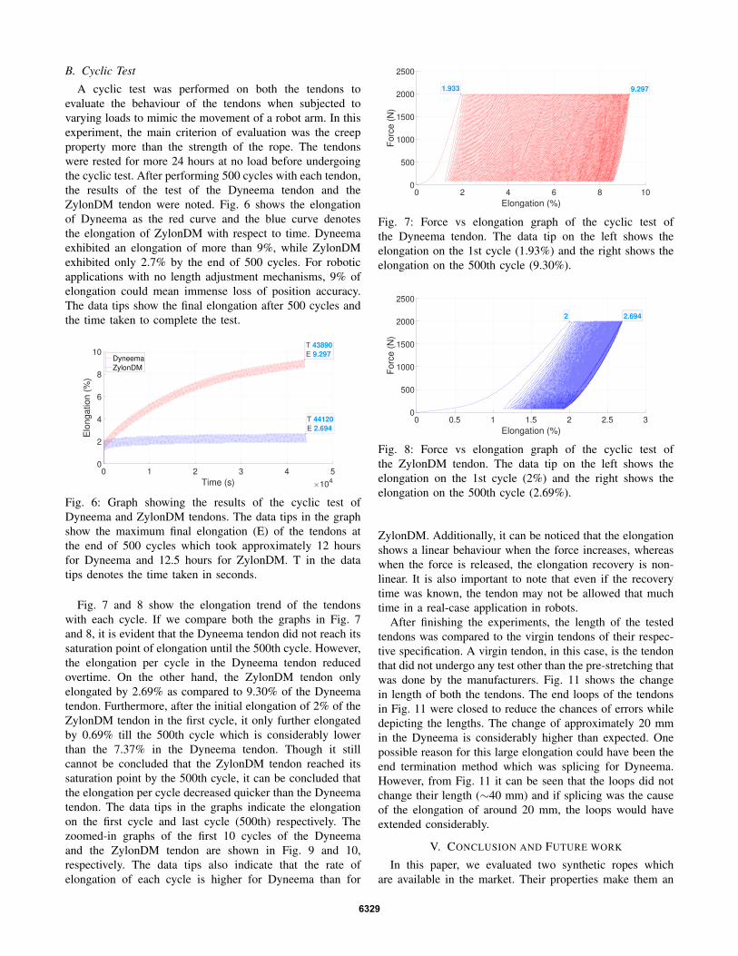
Fig. 2: Dyneema (top) with spliced eye loops and ZylonDM(bottom) with sown eye loops test samples used in theexperiments.
tendon with sown lopes of 40 mm in length which is 4 timesthe diameter of the mounting shaft and with 50 mm ofsewing.
The total length of the tendons used in the experimentswas 240 mm for the Dyneema rope and 241 mm for theZylonDM before the tests. Fig. 2 shows a picture of thetest samples used in the experiments. Both terminal fixationmethods used in this paper (splicing and sewing), accordingto previous works, support far higher loads than the 2 kNused in our experiments.
B. Tests and Experimental Setup
In robotic applications of a tendon rope, one of the mostimportant factors is the strain behaviour of the rope. Toanalyse the strain behaviour, we used a universal testingmachine. In particular, we utilized a SHIMADZU AutographAG-X plus which had a maximum tensile loading capacityof 250 kN. The load cell in the testing machine also hada maximum rated capacity of 250 kN. The machine uses adirect, high-precision, constant-rate strain control using non-backlash precision ball-screw drive and is equipped with ahigh precision load cell. The machine has 3 basic testingmodes, Single, Control and Cycle, and for the experimentswe used Control mode for the tensile test, which formsthe bedding-in process, and Cycle mode for the cyclic test.Each tendon went through the tensile test first and the same
6327

tendon was used in the cyclic test afterwards. A maximumtensile load of 2 kN was used for the experiments and’Force control’ technique was used to control and limit theapplied load and monitor the stroke which corresponds to theelongation of the rope. Based on our experience and after afew trial tests, we used two load acting speeds (v), 1 N/secand 50 N/sec and the data sampling rate was set to 50 msfor the bedding-in process and 0.5 s for the cyclic test. Thetests were programmed as depicted in Fig. 3.
Even though the manufacturers already performed abedding-in process, we ran our own bedding-in cycle tocheck it in a controlled environment. The bedding-in processwas carried out using a controlled tensile test with a slowincrease in load till 70 N, then the load was kept at 70N for15 s, which was followed by a rapid increase in load until2 kN. The tendons were held at 2 kN for 10 min to observethe behaviour at constant load and the load was then releaseddown to 70 N and held for another 10 min to monitor theelongation and recovery. While controlling the tensile forcethat was applied by the machine, the stroke was monitoredwhich is the displacement of the mount in the longitudinaldirection. After mounting each tendon on the machine, thestroke was set to 0 mm when the force in the tendon was0 N without any slack in the tendon. Hence, the strokedirectly resembled the amount of elongation experienced bythe tendon during the experiment. As the tendons had loopson both ends, it was not necessary to use a special apparatusfor testing the ropes in either test. 2 kN is used as the appliedload because it was calculated to be the required strength inour application in a robot arm. The rated tensile strength ofboth ropes far exceeds 2 kN.
Fig. 3: Sequential flow of actions set up in the machine forthe bedding-in process (left) and cyclic test (right).
IV. RESULTS AND DISCUSSIONS
A. Bedding-in Process
The bedding-in process was carried out using a tensiletest on each of the tendons and the results were noted.Fig. 4 shows the elongation curves obtained based on thedata acquired from the first tensile test. The elongation trendof the Dyneema tendon against time is shown by the redcurve and the blue curve shows the elongation trend ofthe ZylonDM tendon whereas the black curve shows theforce applied over time. The Dyneema tendon extended bya maximum of 2.87% and the ZylonDM tendon by 2.27%.The data tips in the graph show the elongation (from left toright) when the force first reached 2 kN, after a constant loadof 2 kN for 10 min, when the force was dropped to 70 N andafter the force was held at 70 N for 10 min. It can be seen thatthe ZylonDM tendon has a flatter curve at constant load thanDyneema and extends by 0.18% only as opposed to 0.46%with Dyneema. The immediate recovery of both the tendonsis similar, i.e. the ZylonDM tendon recovers immediately by0.87% and Dyneema recovers by 0.75%. Furthermore, theovertime or slow recovery of the ZylonDM tendon is 0.12%and that of Dyneema is 0.29%. From Fig. 4, it is also evidentthat both the tendons do not recover the elongation as soon asthe load is reduced. Fig. 5 gives us a clear illustration of theelongation curves where ZylonDM outperforms Dyneema.
0 200 400 600 800 1000 1200 1400
Time (s)
0
500
1000
1500
2000
2500
Forc
e (
N)
0
0.5
1
1.5
2
2.5
3
Elo
ngation (
%)
Force
Dyneema
ZylonDM
1.387
2.117
2.869
1.27
1.827
2.081
2.413
2.265
Fig. 4: Results of the tensile test with force in Newtons andtendon elongation in percentage.
0 0.5 1 1.5 2 2.5 3
Elongation (%)
0
500
1000
1500
2000
2500
Forc
e (
N)
Dyneema
ZylonDM
Fig. 5: Force vs elongation graph illustrating the results ofthe bedding-in process of Dyneema and ZylonDM.
6328
B. Cyclic Test
A cyclic test was performed on both the tendons toevaluate the behaviour of the tendons when subjected tovarying loads to mimic the movement of a robot arm. In thisexperiment, the main criterion of evaluation was the creepproperty more than the strength of the rope. The tendonswere rested for more 24 hours at no load before undergoingthe cyclic test. After performing 500 cycles with each tendon,the results of the test of the Dyneema tendon and theZylonDM tendon were noted. Fig. 6 shows the elongationof Dyneema as the red curve and the blue curve denotesthe elongation of ZylonDM with respect to time. Dyneemaexhibited an elongation of more than 9%, while ZylonDMexhibited only 2.7% by the end of 500 cycles. For roboticapplications with no length adjustment mechanisms, 9% ofelongation could mean immense loss of position accuracy.The data tips show the final elongation after 500 cycles andthe time taken to complete the test.
0 1 2 3 4 5
Time (s) 104
0
2
4
6
8
10
Elo
ngation (
%)
Dyneema
ZylonDM
T 44120
E 2.694
T 43890
E 9.297
Fig. 6: Graph showing the results of the cyclic test ofDyneema and ZylonDM tendons. The data tips in the graphshow the maximum final elongation (E) of the tendons atthe end of 500 cycles which took approximately 12 hoursfor Dyneema and 12.5 hours for ZylonDM. T in the datatips denotes the time taken in seconds.
Fig. 7 and 8 show the elongation trend of the tendonswith each cycle. If we compare both the graphs in Fig. 7and 8, it is evident that the Dyneema tendon did not reach itssaturation point of elongation until the 500th cycle. However,the elongation per cycle in the Dyneema tendon reducedovertime. On the other hand, the ZylonDM tendon onlyelongated by 2.69% as compared to 9.30% of the Dyneematendon. Furthermore, after the initial elongation of 2% of theZylonDM tendon in the first cycle, it only further elongatedby 0.69% till the 500th cycle which is considerably lowerthan the 7.37% in the Dyneema tendon. Though it stillcannot be concluded that the ZylonDM tendon reached itssaturation point by the 500th cycle, it can be concluded thatthe elongation per cycle decreased quicker than the Dyneematendon. The data tips in the graphs indicate the elongationon the first cycle and last cycle (500th) respectively. Thezoomed-in graphs of the first 10 cycles of the Dyneemaand the ZylonDM tendon are shown in Fig. 9 and 10,respectively. The data tips also indicate that the rate ofelongation of each cycle is higher for Dyneema than for
0 2 4 6 8 10
Elongation (%)
0
500
1000
1500
2000
2500
Forc
e (
N)
1.933 9.297
Fig. 7: Force vs elongation graph of the cyclic test ofthe Dyneema tendon. The data tip on the left shows theelongation on the 1st cycle (1.93%) and the right shows theelongation on the 500th cycle (9.30%).
0 0.5 1 1.5 2 2.5 3
Elongation (%)
0
500
1000
1500
2000
2500
Forc
e (
N)
2 2.694
Fig. 8: Force vs elongation graph of the cyclic test ofthe ZylonDM tendon. The data tip on the left shows theelongation on the 1st cycle (2%) and the right shows theelongation on the 500th cycle (2.69%).
ZylonDM. Additionally, it can be noticed that the elongationshows a linear behaviour when the force increases, whereaswhen the force is released, the elongation recovery is non-linear. It is also important to note that even if the recoverytime was known, the tendon may not be allowed that muchtime in a real-case application in robots.
After finishing the experiments, the length of the testedtendons was compared to the virgin tendons of their respec-tive specification. A virgin tendon, in this case, is the tendonthat did not undergo any test other than the pre-stretching thatwas done by the manufacturers. Fig. 11 shows the changein length of both the tendons. The end loops of the tendonsin Fig. 11 were closed to reduce the chances of errors whiledepicting the lengths. The change of approximately 20 mmin the Dyneema is considerably higher than expected. Onepossible reason for this large elongation could have been theend termination method which was splicing for Dyneema.However, from Fig. 11 it can be seen that the loops did notchange their length (∼40 mm) and if splicing was the causeof the elongation of around 20 mm, the loops would haveextended considerably.
V. CONCLUSION AND FUTURE WORK
In this paper, we evaluated two synthetic ropes whichare available in the market. Their properties make them an
6329

1 1.5 2 2.5
Elongation (%)
0
500
1000
1500
2000F
orc
e (
N)
2.435
1.7251.256
1.933
Fig. 9: Force vs elongation graph showing a zoomed plot ofthe first 10 cycles of the cyclic test of the Dyneema tendon.The data tip on the top-left shows the elongation on the 1stcycle (1.93%) whereas the data tip on the top-right showsthe elongation at the 10th cycle (2.44%) and the bottom-leftshows the elongation at the end of the 1st cycle (1.26%) andbottom-right tip shows the elongation at the end of the 10thcycle (%1.73).
1 1.2 1.4 1.6 1.8 2 2.2
Elongation (%)
0
500
1000
1500
2000
Forc
e (
N)
2
1.139
1.352
2.176
Fig. 10: Force vs elongation graph showing a zoomed plot ofthe first 10 cycles of the cyclic test of the ZylonDM tendon.The data tip on the top-left shows the elongation on the1st cycle (2%) whereas the data tip on the top-right showsthe elongation at the 10th cycle (2.18%) and the bottom-leftshows the elongation at the end of the 1st cycle (1.14%) andbottom-right tip shows the elongation at the end of the 10thcycle (%1.35).
interesting choice for many applications, including robotics.Both tested materials claim to exhibit negligible creep,and we investigated their elongation behaviour under cyclicloading.
A Dyneema DM20 rope and a rope made from ZylonAS (PBO) as the core and Dyneema (SK, IZANAS) asthe sleeve, which we named ZylonDM, were tested. Forthe terminal fixation method, the ZylonDM used sewinginstead of splicing. A tensile test was performed to bed-in the tendons and a cyclic test was performed to test thestrain behaviour of the tendons against load and time. It wasdeduced that the ZylonDM tendon showed better resistanceto all forms of creep regimes than Dyneema. It was alsoverified from the results that the cause of the unexpectedelongation of ∼20 mm in the Dyneema tendon was not dueto the different end terminal fixation technique.
(a) Virgin (Left) &Post-experiment (Right)Dyneema Tendon
(b) Virgin (Left) & Post-experiment (Right) Zy-lonDM Tendon
Fig. 11: Comparison of lengths of tendons after all theexperiments to a virgin tendon. The Dyneema tendon showsa plastic elongation of almost ∼20 mm whereas ZylonDMonly extended by ∼4 mm.
Overall, while both tendons exhibited noteworthy elon-gation behaviour, the ZylonDM tendon exhibited lower andmore stable elongation.
However, it should also be mentioned that previous workfound that Zylon experiences significant loss of tensilestrength during repeated bending [9]. Moreover, Zylon issomewhat stiffer than Dyneema. Therefore, it depends onthe application which synthetic fibre is better.
The areas of application for both tendons can be widenedby including a length adjustment mechanism in the system.
In the future, we plan to study the visco-elasticity regimein further detail and mainly, the recovery time of this regime.Also, further tests to analyse the behaviour of the tendon afterit has reached an elongation saturation point are planned.
ACKNOWLEDGMENT
The authors would like to thank Associate Professor GenEndo of School of Engineering, Tokyo Institute of Technol-ogy, Tokyo for his expert advice on synthetic fibre ropes. Theauthors would also like to thank Material Science Laboratory,Waseda University for lending us the testing machine. Oursincere gratitude also goes to Hayami Industry, Japan andPaul Ekas of SAKE Robotics for manufacturing the ropes toour custom needs.
REFERENCES
[1] A. Schmitz, U. Pattacini, F. Nori, L. Natale, G. Metta, and G. Sandini,“Design, realization and sensorization of the dexterous icub hand,” in2010 10th IEEE-RAS International Conference on Humanoid Robots,Dec 2010, pp. 186–191.
6330

[2] M. Controzzi, C. Cipriani, and M. C. Carrozza, Design of ArtificialHands: A Review. Springer International Publishing, 2014, pp. 219–246.
[3] A. Mottard, T. Laliberte, and C. Gosselin, “Underactuated tendon-driven robotic/prosthetic hands: design issues,” in Robotics: Scienceand Systems, 07 2017.
[4] B. Rooks, “The harmonious robot,” Industrial Robot: An InternationalJournal, vol. 33, no. 2, 2006.
[5] Y. Nakanishi, Y. Asano, T. Kozuki, H. Mizoguchi, Y. Motegi, M. Os-ada, T. Shirai, J. Urata, K. Okada, and M. Inaba, “Design concept ofdetail musculoskeletal humanoid “Kenshiro” - toward a real humanbody musculoskeletal simulator,” in 2012 12th IEEE-RAS Interna-tional Conference on Humanoid Robots (Humanoids 2012), Nov 2012,pp. 1–6.
[6] I. Gaponov, D. Popov, and J.-H. Ryu, “Twisted string actuationsystems: A study of the mathematical model and a comparison oftwisted strings,” IEEE/ASME Transactions on Mechatronics, vol. 19,pp. 1–12, 08 2014.
[7] T. Helps, M. Taghavi, S. Wang, and J. Rossiter, “Twistedrubber variable-stiffness artificial muscles,” Soft Robotics, vol. 7,no. 3, pp. 386–395, 2020, pMID: 31855114. [Online]. Available:https://doi.org/10.1089/soro.2018.0129
[8] V. Arakelian, “Gravity compensation in robotics,” Advanced Robotics,vol. 30, pp. 1–18, 11 2015.
[9] A. Horigome and G. Endo, “Investigation of repetitive bending dura-bility of synthetic fiber ropes,” IEEE Robotics and Automation Letters,vol. 3, no. 3, pp. 1779–1786, July 2018.
[10] T. Treratanakulwong, H. Kaminaga, and Y. Nakamura, “Low-frictiontendon-driven robot hand with carpal tunnel mechanism in the palmby optimal 3d allocation of pulleys,” in 2014 IEEE InternationalConference on Robotics and Automation (ICRA), May 2014, pp. 6739–6744.
[11] W. Friedl, M. Chalon, J. Reinecke, and M. Grebenstein, “”FRCEF:The new friction reduced and coupling enhanced finger for theAwiwi hand”,” in 2015 IEEE-RAS 15th International Conference onHumanoid Robots (Humanoids), Nov 2015, pp. 140–147.
[12] S. Kitano, S. Hirose, A. Horigome, and G. Endo, “TITAN-XIII:sprawling-type quadruped robot with ability of fast and energy-efficient walking,” Robomech Journal, vol. 3, no. 8, 2016.
[13] M. Mori, K. Suzumori, S. Seita, M. Takahashi, T. Hosoya, andK. Kusumoto, “Development of very high force hydraulic McKibbenartificial muscle and its application to shape-adaptable power hand,”in 2009 IEEE International Conference on Robotics and Biomimetics(ROBIO), Dec 2009, pp. 1457–1462.
[14] A. Horigome, H. Yamada, G. Endo, S. Sen, S. Hirose, and E. F.Fukushima, “Development of a coupled tendon-driven 3D multi-jointmanipulator,” in 2014 IEEE International Conference on Robotics andAutomation (ICRA), May 2014, pp. 5915–5920.
[15] A. Horigome, G. Endo, A. Takata, and Y. Wakabayashi, “Developmentof new terminal fixation method for synthetic fiber ropes,” IEEERobotics and Automation Letters, vol. 3, no. 4, pp. 4321–4328, Oct2018.
[16] M. P. Summers, “Rope selection for rope drive transmissions used inrobotic manipulation,” 2010.
[17] J. Flory, V. Ahjem, and S. Banfield, “A new method of testing forchange-in-length properties of large fiber-rope deepwater mooringlines,” in Offshore Technology Conference, 2001, pp. 1087–1096.
[18] F. Sloan, S. Bull, and R. Longerich, “Design modifications to in-crease fatigue life of fiber ropes,” in Proceedings of OCEANS 2005MTS/IEEE, vol. 1, Sep. 2005, pp. 829–835.
[19] M. P. Vlasblom and R. L. M. Bosman, “Predicting the creep lifetimeof HMPE mooring rope applications,” in OCEANS 2006, Sep. 2006,pp. 1–10.
[20] P. Davies, Y. Reaud, L. Dussud, and P. Woerther, “Mechanicalbehaviour of HMPE and aramid fibre ropes for deep sea handlingoperations,” Ocean Engineering - OCEAN ENG, vol. 38, 12 2011.
[21] M. Vlasblom, J. Boesten, S. Leite, and P. Davies, “Development ofHMPE fiber for permanent deepwater offshore mooring,” in OffshoreTechnology Conference, 2012.
[22] H. Liu, W. Huang, Y. Lian, and L. Li, “An experimentalinvestigation on nonlinear behaviors of synthetic fiber ropesfor deepwater moorings under cyclic loading,” Applied OceanResearch, vol. 45, pp. 22 – 32, 2014. [Online]. Available:http://www.sciencedirect.com/science/article/pii/S0141118713001120
[23] Y. Lian, J. Zheng, and H. Liu, “An investigation on creep and creep-rupture behaviors of HMPE ropes,” Journal of Offshore Mechanicsand Arctic Engineering, vol. 140, 11 2017.
[24] H. Werff, M. Vlasblom, L. Balzano, T. Engels, U. Heisserer, F. Oost-erlinck, and B. Coussens, “New developments of the dyneema R© ultrahigh molecular weight polyethylene fiber,” 01 2014.
[25] S. Vannei, Y. Mizutani, G. Endo, Y. Suzuki, and A. Todoroki, “Con-secutive impact loading and preloading effect on stiffness of wovensynthetic-fiber rope,” Journal of Textile Science and Technology, vol. 3,pp. 1–16, 02 2017.
[26] J. Kirchhoff and O. von Stryk, “New insights in synthetic fiber ropeelongation and its detection for ultra lightweight tendon driven serieselastic robots,” in 2017 IEEE International Conference on AdvancedIntelligent Mechatronics (AIM), July 2017, pp. 64–69.
[27] https://www.toyobo.co.jp/seihin/kc/pbo/Zyneema-p/bussei-p/technical.pdf, accessed February 29, 2020.
[28] X. Liu and W. Yu, “The degradation of PBO fiber by heat and light,”Research Journal of Textile and Apparel, vol. 1, pp. 343–348, 01 2005.
[29] https://www.samsonrope.com/catalog/rope-users-manual/, accessedFebruary 29, 2020.
6331