a study on loaded tooth contact analysis of a cycloid
TRANSCRIPT
Bulletin of the JSME
Journal of Advanced Mechanical Design, Systems, and ManufacturingVol.11, No.6, 2017
Paper No.17-00213© 2017 The Japan Society of Mechanical Engineers[DOI: 10.1299/jamdsm.2017jamdsm0077]
1. Introduction
The demand on gear drives of automation machinery increases recently, so as to reduce the labor cost and to improve the productivity. Precise motion and high power transmission are the essential requirements for development of such the gear drives. Among various types of gear drives, the reducers combined with involute and cycloid planetary gears play an important role to fulfill this requirement. This type of gear drives, i.e., so-called RV-drives (Fig. 1), has not only the advantage in high gear ratio, but also the good performances to share the transmitted load and to absorb the shock because of multiple tooth-pairs in contact. The conventional involute planetary gear, by contrast, can not fulfill the extreme requirements.
Besides the geometrical design of the tooth profiles for the backlash and the transmission accuracy, the load analysis is the most important issue for successful application of such the drives. Two essential tasks must be handled for the analysis. First, the statically indeterminate contact problem of multiple tooth pairs should be solved. Second, the influences of the stiffness of components, the friction, the flank modification and the assembly/manufacturing errors on acting loads should be considered in the analysis model.
Some calculation approaches for load analysis of the mentioned cycloid planetary gear drives can be fund in some but a little research papers. For example, Dong et al. (1996) proposed a calculation approach for calculating the acting forces in the cycloidal gear drive, where the bearing stiffness is assumed as the same. Blanche and Yang (1989, 1990) analyzed the influence of the manufacturing errors on the transmitted load and transmission errors. Hidaka et al. (1994) proposed an analytical method to analyze the influence of manufacturing errors. The analytical approach is later compared with FEM analysis by Ishida et al. (1996). Gorla et al. (2008) develop a simplified approach to analyze the
1
A study on loaded tooth contact analysis of a cycloid planetary gear reducer considering friction and bearing roller stiffness
Ching-Hao HUANG* and Shyi-Jeng TSAI* *Department of Mechanical Engineering, National Central University
No. 300, Zhongda Rd., Zhongli District, Taoyuan City 32001, Taiwan
E-mail: [email protected]
Received: 10 April 2017; Revised: 17 May 2017; Accepted: 31 May 2017
Abstract The cycloid planetary gear drives designed in the so-called RV-type play an important role in precision power transmission. Not only the high reduction ratio, but also the shock absorbability is the significant advantage. However, the load analysis of such the drive is complicated, because the contact problem of the multiple tooth pairs is statically indeterminate. The aim of the paper is thus to propose a computerized approach of loaded tooth contact analysis (LTCA) based on the influence coefficient method, either for the contact tooth pairs of the involute stage or of the cycloid stage. The contact points are determined based on the instant center of velocity in the model. On the other hand, the shared loads of multiple contact tooth pairs are calculated numerically with a set of equations according to the relations of deformation-displacement and load equilibrium. The coupled influences of the loads acting on the involute and the cycloid tooth pairs are also analyzed considering the friction on the contact tooth flanks as well as the stiffness of the supporting bearings for the cycloid discs. With an industrial example, the contact pattern with distributed contact stresses and the shared load of each contact tooth pair during operation are simulated with aid of the proposed approach. The transmitted torques on the crankshaft, the displacements of the main components and the efficiency of each stage calculated accordingly are also illustrated in the paper.
Keywords: Loaded tooth contact analysis, Cycloid planetary gear reducer, Bearing roller stiffness, Friction, Load sharing, Contact stress
2© 2017 The Japan Society of Mechanical Engineers[DOI: 10.1299/jamdsm.2017jamdsm0077]
Huang and Tsai, Journal of Advanced Mechanical Design, Systems, and Manufacturing, Vol.11, No.6 (2017)
contact stress and also conducted an experiment to validate the theoretical analysis results. Another approach for load analysis of the cycloid gear drives is the finite element method (FEM). It is the mostly applied method and can be found in some of the research papers, for example, Blagojevic et al. (2011), Kim et al. (2009), Li (2014) and Thube and Bobak (2012). However, the simulated results of the shared load and contact stress are strongly affected by the accuracy and the configuration of the element meshing because of the multiple contact tooth pairs.
An alternative numerical approach other than FEM, i.e. loaded tooth contact analysis (LTCA) approach, is also developed. The unknown shared loads of the multiple contact tooth pairs are solved numerically with a set of derived analytical equations. The essential equations are divided into two types of relations, namely the equations of deformation-displacement and the equations of load equilibrium. The LTCA approach is applied successfully in the involute gear drives, e.g., Schulze et al. (2009), Wu and Tsai (2009), Leque and Kahraman (2015), Neubauer et al. (2015), Ye and Tsai (2016). However it is less applied in the cycloid planetary gear drives.
The authors have thus developed an LTCA approach based on the influence coefficient method to analyze the contact characteristics of the cycloid tooth pairs (Tsai et al., 2015a, 2015b). Because only the cycloid stage is considered in the mentioned two papers, a complete LTCA model including both the involute and cycloid gear stage is further developed in this paper. The coupled influences of the loads acting on the involute and the cycloid gears are therefore studied considering the influences of the friction on the contact tooth flanks as well as the stiffness of the supporting bearings for the cycloid discs. However, flank modification and errors are not present in the paper in order to simplify the model. With aid of the proposed LTCA approach not only the contact characteristics, e.g., the shared loads, the contact patterns with distributed contact stress, and the transmitted torques, but also the displacements and the efficiency can be analyzed. The effective performances of the proposed LTCA approach are also represented in the paper with an example from industrial application.
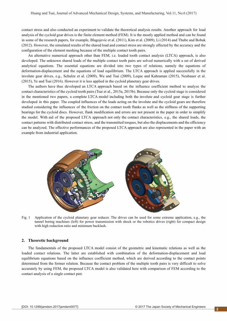
Fig. 1 Application of the cycloid planetary gear reducer. The drives can be used for some extreme application, e.g., the
tunnel boring machines (left) for power transmission with shock or the robotics drives (right) for compact design with high reduction ratio and minimum backlash.
2. Theoretic background
The fundamentals of the proposed LTCA model consist of the geometric and kinematic relations as well as the loaded contact relations. The latter are established with combination of the deformation-displacement and load equilibrium equations based on the influence coefficient method, which are derived according to the contact points determined from the former relation. Because the contact problem of the multiple tooth pairs is very difficult to solve accurately by using FEM, the proposed LTCA model is also validated here with comparison of FEM according to the contact analysis of a single contact pair.
2

2© 2017 The Japan Society of Mechanical Engineers[DOI: 10.1299/jamdsm.2017jamdsm0077]
Huang and Tsai, Journal of Advanced Mechanical Design, Systems, and Manufacturing, Vol.11, No.6 (2017)
2.1 Geometric and kinematic relations
2.1.1 Structural characteristics
The proposed reducer consists of an involute gear stage and a cycloid stage with two discs. As the structure in Fig. 2 shows, the involute gear stage is a planetary gear drive without a ring-gear, each planet gear is mounted on the crankshaft. This structure enables the power split through the three crankshafts to improve the shaft stiffness problem from the traditional “Cyclo-drive” design. The split power is combined again in the cycloid stage to the output element, namely either the pin wheel or the carrier. Another advantage comes from ease of controlling the accuracy. The cycloid gear stage is similar to the planetary gear system without a sun gear. The three crank shafts drive the two cycloid discs to perform a differential motion. In this stage, each of the two cycloid discs are supported by bearing rollers with a cage, Fig. 3, and arranged with a phase angle 180° to balance the eccentric forces.
The reduction ratio of the reducer can be calculated with the stationary gear ratio ug of the involute gear stage and the gear ratio uc of the cycloid stage, i.e.,
1
2g z
zu , and (1)
34
4c zz
zu
. (2)
The final reduction ratio is calculated according to the two application conditions: (a) the pin-wheel as the output and the carrier as fixed,
cg uuu , and (3)
(b) the carrier as the output and the pin-wheel as fixed,
cg1 uuu . (4)
Fig. 2 The structure of the RV reducer. It consists of an involute planetary gear stage and a cycloid planetary gear stage,
usually with two discs. The input power is split by the three involute planetary gear, and combined again through the cycloid discs to the pin wheel or the carrier.
3
2© 2017 The Japan Society of Mechanical Engineers[DOI: 10.1299/jamdsm.2017jamdsm0077]
Huang and Tsai, Journal of Advanced Mechanical Design, Systems, and Manufacturing, Vol.11, No.6 (2017)
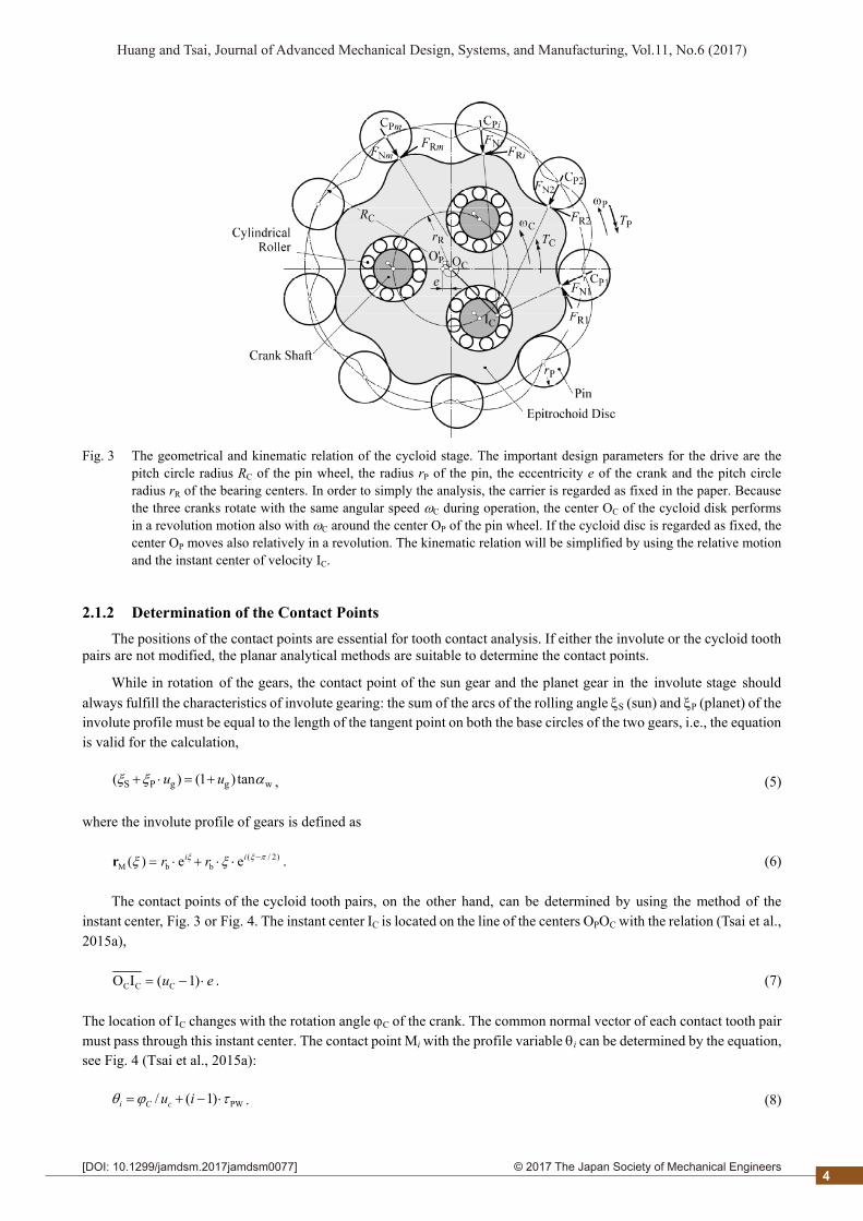
Fig. 3 The geometrical and kinematic relation of the cycloid stage. The important design parameters for the drive are the
pitch circle radius RC of the pin wheel, the radius rP of the pin, the eccentricity e of the crank and the pitch circle radius rR of the bearing centers. In order to simply the analysis, the carrier is regarded as fixed in the paper. Because the three cranks rotate with the same angular speed C during operation, the center OC of the cycloid disk performs in a revolution motion also with C around the center OP of the pin wheel. If the cycloid disc is regarded as fixed, the center OP moves also relatively in a revolution. The kinematic relation will be simplified by using the relative motion and the instant center of velocity IC.
2.1.2 Determination of the Contact Points
The positions of the contact points are essential for tooth contact analysis. If either the involute or the cycloid tooth pairs are not modified, the planar analytical methods are suitable to determine the contact points.
While in rotation of the gears, the contact point of the sun gear and the planet gear in the involute stage should always fulfill the characteristics of involute gearing: the sum of the arcs of the rolling angle S (sun) and P (planet) of the involute profile must be equal to the length of the tangent point on both the base circles of the two gears, i.e., the equation is valid for the calculation,
wggPS tan)1()( uu , (5)
where the involute profile of gears is defined as
)2/(bbM ee)( ii rrr . (6)
The contact points of the cycloid tooth pairs, on the other hand, can be determined by using the method of the instant center, Fig. 3 or Fig. 4. The instant center IC is located on the line of the centers OPOC with the relation (Tsai et al., 2015a),
eu )1(IO CCC . (7)
The location of IC changes with the rotation angle C of the crank. The common normal vector of each contact tooth pair must pass through this instant center. The contact point Mi with the profile variable i can be determined by the equation, see Fig. 4 (Tsai et al., 2015a):
PW)1(/ iucCi . (8)
4
2© 2017 The Japan Society of Mechanical Engineers[DOI: 10.1299/jamdsm.2017jamdsm0077]
Huang and Tsai, Journal of Advanced Mechanical Design, Systems, and Manufacturing, Vol.11, No.6 (2017)
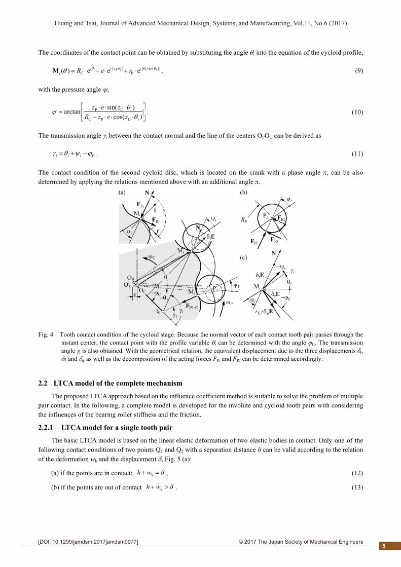
The coordinates of the contact point can be obtained by substituting the angle i into the equation of the cycloid profile,
)]([P
)(C eee)( 4 iiii izii
i reR M , (9)
with the pressure angle ,
)cos()sin(arctan
CPC
CP
i
i
zezRzez
. (10)
The transmission angle i between the contact normal and the line of the centers OPOC can be derived as
C iii . (11)
The contact condition of the second cycloid disc, which is located on the crank with a phase angle , can be also determined by applying the relations mentioned above with an additional angle .
Fig. 4 Tooth contact condition of the cycloid stage. Because the normal vector of each contact tooth pair passes through the instant center, the contact point with the profile variable i can be determined with the angle C. The transmission angle i is also obtained. With the geometrical relation, the equivalent displacement due to the three displacements t, r and as well as the decomposition of the acting forces FPi and FRi can be determined accordingly.
2.2 LTCA model of the complete mechanism
The proposed LTCA approach based on the influence coefficient method is suitable to solve the problem of multiple pair contact. In the following, a complete model is developed for the involute and cycloid tooth pairs with considering the influences of the bearing roller stiffness and the friction.
2.2.1 LTCA model for a single tooth pair
The basic LTCA model is based on the linear elastic deformation of two elastic bodies in contact. Only one of the following contact conditions of two points Q1 and Q2 with a separation distance h can be valid according to the relation of the deformation wk and the displacement , Fig. 5 (a):
(a) if the points are in contact: kwh , (12)
(b) if the points are out of contact kwh . (13)
5
2© 2017 The Japan Society of Mechanical Engineers[DOI: 10.1299/jamdsm.2017jamdsm0077]
Huang and Tsai, Journal of Advanced Mechanical Design, Systems, and Manufacturing, Vol.11, No.6 (2017)
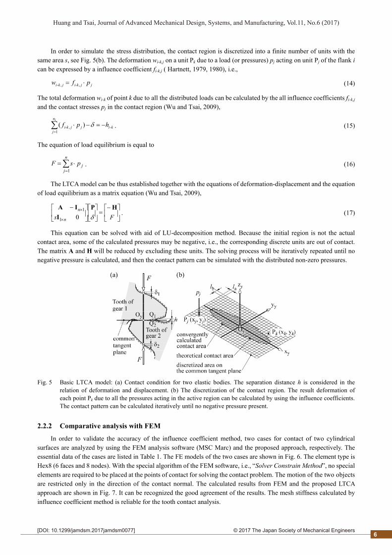
In order to simulate the stress distribution, the contact region is discretized into a finite number of units with the same area s, see Fig. 5(b). The deformation wi-k,j on a unit Pk due to a load (or pressures) pj acting on unit Pj of the flank i can be expressed by a influence coefficient fi-k,j ( Hartnett, 1979, 1980), i.e.,
jji-kjki pfw ,,- (14)
The total deformation wi-k of point k due to all the distributed loads can be calculated by the all influence coefficients fi-k,j and the contact stresses pj in the contact region (Wu and Tsai, 2009),
ki
n
jjji-k hpf
i
-1
, )(
. (15)
The equation of load equilibrium is equal to
n
jjpsF
1. (16)
The LTCA model can be thus established together with the equations of deformation-displacement and the equation of load equilibrium as a matrix equation (Wu and Tsai, 2009),
Fs n
n HP
I
IA
01
1 . (17)
This equation can be solved with aid of LU-decomposition method. Because the initial region is not the actual contact area, some of the calculated pressures may be negative, i.e., the corresponding discrete units are out of contact. The matrix A and H will be reduced by excluding these units. The solving process will be iteratively repeated until no negative pressure is calculated, and then the contact pattern can be simulated with the distributed non-zero pressures.
Fig. 5 Basic LTCA model: (a) Contact condition for two elastic bodies. The separation distance h is considered in the relation of deformation and displacement. (b) The discretization of the contact region. The result deformation of each point Pk due to all the pressures acting in the active region can be calculated by using the influence coefficients. The contact pattern can be calculated iteratively until no negative pressure present.
2.2.2 Comparative analysis with FEM
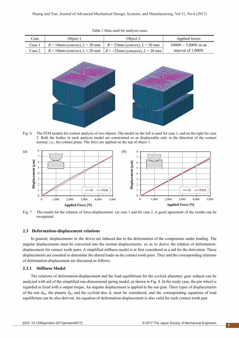
In order to validate the accuracy of the influence coefficient method, two cases for contact of two cylindrical surfaces are analyzed by using the FEM analysis software (MSC Marc) and the proposed approach, respectively. The essential data of the cases are listed in Table 1. The FE models of the two cases are shown in Fig. 6. The element type is Hex8 (6 faces and 8 nodes). With the special algorithm of the FEM software, i.e., “Solver Constrain Method”, no special elements are required to be placed at the points of contact for solving the contact problem. The motion of the two objects are restricted only in the direction of the contact normal. The calculated results from FEM and the proposed LTCA approach are shown in Fig. 7. It can be recognized the good agreement of the results. The mesh stiffness calculated by influence coefficient method is reliable for the tooth contact analysis.
6
2© 2017 The Japan Society of Mechanical Engineers[DOI: 10.1299/jamdsm.2017jamdsm0077]
Huang and Tsai, Journal of Advanced Mechanical Design, Systems, and Manufacturing, Vol.11, No.6 (2017)
Table 1 Data used for analysis cases
Case Object 1 Object 2 Applied forces Case 1 R = 10mm (convex), L = 20 mm R = 25mm (convex), L = 20 mmCase 2 R = 10mm (convex), L = 20 mm R = 25mm (concave), L = 20 mm
1000N ~ 5,000N in an interval of 1,000N
Fig. 6 The FEM models for contact analysis of two objects. The model on the left is used for case 1, and on the right for case 2. Both the bodies in each analysis model are constrained so as displaceable only in the direction of the contact normal, i.e., the contact plane. The force are applied on the top of object 1.
(a)
0
1
2
3
4
5
6
7
8
0 1,000 2,000 3,000 4,000 5,000
Dis
plac
emen
t [
m]
Applied Force [N]
IC FEM
(b)
0
1
2
3
4
5
6
7
8
0 1,000 2,000 3,000 4,000 5,000
Dis
pla
cem
ent
[m
]
Applied Force [N]
IC FEM
Fig. 7 The results for the relation of force-displacement: (a) case 1 and (b) case 2. A good agreement of the results can be recognized.
2.3 Deformation-displacement relations
In general, displacements in the drives are induced due to the deformation of the components under loading. The angular displacements must be converted into the normal displacements, so as to derive the relation of deformation- displacement for contact tooth pairs. A simplified stiffness model is at first considered as a aid for the derivation. These displacements are essential to determine the shared loads on the contact tooth pairs. They and the corresponding relations of deformation-displacement are discussed as follows.
2.3.1 Stiffness Model
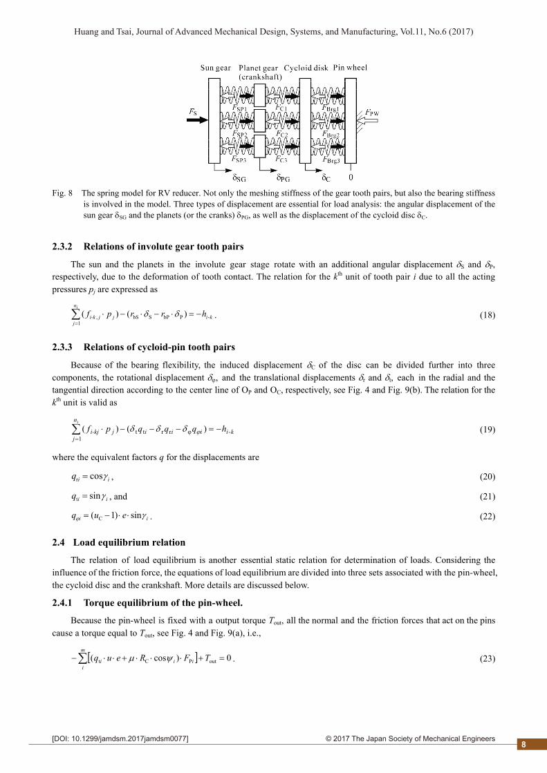
The relations of deformation-displacement and the load equilibrium for the cycloid planetary gear reducer can be analyzed with aid of the simplified one-dimensional spring model, as shown in Fig. 8. In the study case, the pin wheel is regarded as fixed with a output torque. An angular displacement is applied to the sun gear. Three types of displacements of the sun SG, the planets PG and the cycloid disc C must be considered, and the corresponding equations of load equilibrium can be also derived. An equation of deformation-displacement is also valid for each contact tooth pair.
7
2© 2017 The Japan Society of Mechanical Engineers[DOI: 10.1299/jamdsm.2017jamdsm0077]
Huang and Tsai, Journal of Advanced Mechanical Design, Systems, and Manufacturing, Vol.11, No.6 (2017)
Fig. 8 The spring model for RV reducer. Not only the meshing stiffness of the gear tooth pairs, but also the bearing stiffness is involved in the model. Three types of displacement are essential for load analysis: the angular displacement of the sun gear SG and the planets (or the cranks) PG, as well as the displacement of the cycloid disc C.
2.3.2 Relations of involute gear tooth pairs
The sun and the planets in the involute gear stage rotate with an additional angular displacement S and P, respectively, due to the deformation of tooth contact. The relation for the kth unit of tooth pair i due to all the acting pressures pj are expressed as
ki
n
jjji-k hrrpf
i
-PbPSbS1
, )()(
. (18)
2.3.3 Relations of cycloid-pin tooth pairs
Because of the bearing flexibility, the induced displacement C of the disc can be divided further into three components, the rotational displacement , and the translational displacements r and t, each in the radial and the tangential direction according to the center line of OP and OC, respectively, see Fig. 4 and Fig. 9(b). The relation for the kth unit is valid as
kiiii
n
jji-kj hqqqpf
i
-φrrtt1
)()(
(19)
where the equivalent factors q for the displacements are
iiq cosr , (20)
iiq sint , and (21)
ii euq sin)1( C . (22)
2.4 Load equilibrium relation
The relation of load equilibrium is another essential static relation for determination of loads. Considering the influence of the friction force, the equations of load equilibrium are divided into three sets associated with the pin-wheel, the cycloid disc and the crankshaft. More details are discussed below.
2.4.1 Torque equilibrium of the pin-wheel.
Because the pin-wheel is fixed with a output torque Tout, all the normal and the friction forces that act on the pins cause a torque equal to Tout, see Fig. 4 and Fig. 9(a), i.e.,
0)cos( outPCt TFReuqm
iiii . (23)
8
2© 2017 The Japan Society of Mechanical Engineers[DOI: 10.1299/jamdsm.2017jamdsm0077]
Huang and Tsai, Journal of Advanced Mechanical Design, Systems, and Manufacturing, Vol.11, No.6 (2017)
2.4.2 Load equilibrium of cycloid disc
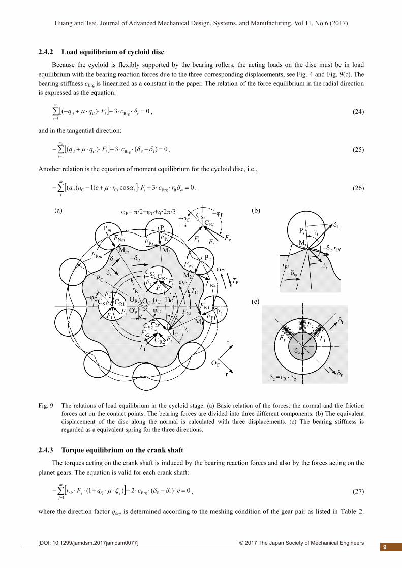
Because the cycloid is flexibly supported by the bearing rollers, the acting loads on the disc must be in load equilibrium with the bearing reaction forces due to the three corresponding displacements, see Fig. 4 and Fig. 9(c). The bearing stiffness cBrg is linearized as a constant in the paper. The relation of the force equilibrium in the radial direction is expressed as the equation:
03)( rBrg1
tr
cFqqim
iiii , (24)
and in the tangential direction:
0)(3)( tPBrg1
rt
cFqqim
iiii . (25)
Another relation is the equation of moment equilibrium for the cycloid disc, i.e.,
03cos)1(( RBrgCCt rcFreuq i
m
iiii . (26)
Fig. 9 The relations of load equilibrium in the cycloid stage. (a) Basic relation of the forces: the normal and the friction forces act on the contact points. The bearing forces are divided into three different components. (b) The equivalent displacement of the disc along the normal is calculated with three displacements. (c) The bearing stiffness is regarded as a equivalent spring for the three directions.
2.4.3 Torque equilibrium on the crank shaft
The torques acting on the crank shaft is induced by the bearing reaction forces and also by the forces acting on the planet gears. The equation is valid for each crank shaft:
0)(2)1( tPBrg1
bP
ecqFrm
jjjj , (27)
where the direction factor qi-j is determined according to the meshing condition of the gear pair as listed in Table 2.
9

2© 2017 The Japan Society of Mechanical Engineers[DOI: 10.1299/jamdsm.2017jamdsm0077]
Huang and Tsai, Journal of Advanced Mechanical Design, Systems, and Manufacturing, Vol.11, No.6 (2017)
Similarly, the torque acting on the sun gear, i.e., the input torque for efficiency calculation, can be calculated as
P
1 1---bSS )1(
n
i
m
jjijiji
i
qFrT . (28)
Table 2 Direction factor for friction force on ivolute flanks
Mesh action Driving gear Driven gear qξ Approach C C Pitch point C C Recess C C
2.5 Separation distance of engaged flanks
According to the proposed LTCA model, the separation distances h between the contact teeth on the contact region are essential for calculation of distributed stresses. It is affected not only by the tooth profiles of both the engaged flanks, but also the arrangement of the gears with or without errors. In the study, only the theoretical profile and ideal arrangement are considered.
2.5.1 Cycloid-pin tooth pairs
The separation distance hj at the position lMj in the direction of the contact normal consists of two parts: the distance hMj of point Mj on the cycloidal flank to the common tangent plane, and the distance hCj of point Cj on the circular pin. The distance hCj is equal to
2M
2ppC jj lrrh . (29)
The separation distance hMj can be determined by the vector relation (Tsai et al., 2015b), Fig. 10(b),
iijjjh MMMM )( nr , (30)
where the profile variable Mj for the position vector rMj is determined by solving the equation,
jij lMMMi tr . (31)
2.5.2 Involute Gear Tooth Pairs.
With the normal nMj and the tangential vector tMj of the contact point, the separation distance hMj of the involute tooth pairs can be also determined by the approach mentioned above, i.e., Eq. (30) and (31) are also valid for involute tooth.
Fig. 10 The topological relations of the contact region. The separation distance hMj the flank point Mj can be determined based on the scalar operations of the vectors.
10
2© 2017 The Japan Society of Mechanical Engineers[DOI: 10.1299/jamdsm.2017jamdsm0077]
Huang and Tsai, Journal of Advanced Mechanical Design, Systems, and Manufacturing, Vol.11, No.6 (2017)
2.6 Formulation of the Matrix Equation
The deformation-displacement equations for involute and cycloid tooth pairs as well as the equations of load equilibrium, which are derived above, can be further expressed in a form of matrix equation as
output
g
c
SG
PG
c
g
c
T
GGCG
CGCC
SGPGG
CC
Tδ
0
0
H
H
δ
δ
P
P
0000S
0KKS0
0KK0S
QQ0A0
00Q0A
. (32)
This equation can be solved with aid of LU-decomposition method effectively. The same convergence approach can be referred in section 2.2.1, or (Wu and Tsai, 2009; Tsai et al., 2015a).
3. Numerical Examples
3.1 Overview of the Gear Reducer
This study case is used for a reducer of pipe-jacking tunneling boring machine. The essential gearing data and the material property are listed in Table 3 and Table 4, respectively. The friction coefficient with the value of 0.1 is applied in the calculation.
Table 3 Gearing data of the Cycloid and Involute Planetary stage
Cycloid Stage Involute Stage Item/variable value Sun Planet Tooth number of cycloid disk 39 Tooth number 18 42 Tooth number of pin wheel 40 Modulus 3 mm P.C.D of pin wheel 325 mm Pressure angle 20∘ Radius of pin 8 mm Center distance 90 mm Radius of the bearing center 180 mm Face-width 36 25 Thickness of cycloid disk 31.5 mm Profile-shifting coefficient 0.17 -0.17 Number of cycloid disk 2 Number of planets -- 3 Number of the crankshaft 3
Table 4 Material data
Items Value Elastic module 207 GPa Poisson’s ratio 0.3 Stiffness of the bearing 106 N/mm Output torque 8000 Nm
3.2 Contact characteristics of involute tooth pair
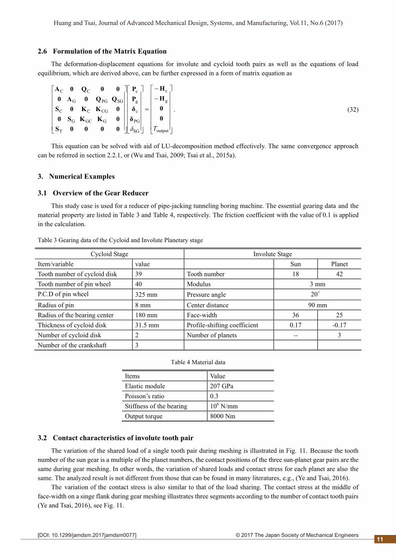
The variation of the shared load of a single tooth pair during meshing is illustrated in Fig. 11. Because the tooth number of the sun gear is a multiple of the planet numbers, the contact positions of the three sun-planet gear pairs are the same during gear meshing. In other words, the variation of shared loads and contact stress for each planet are also the same. The analyzed result is not different from those that can be found in many literatures, e.g., (Ye and Tsai, 2016).
The variation of the contact stress is also similar to that of the load sharing. The contact stress at the middle of face-width on a singe flank during gear meshing illustrates three segments according to the number of contact tooth pairs (Ye and Tsai, 2016), see Fig. 11.
11
2© 2017 The Japan Society of Mechanical Engineers[DOI: 10.1299/jamdsm.2017jamdsm0077]
Huang and Tsai, Journal of Advanced Mechanical Design, Systems, and Manufacturing, Vol.11, No.6 (2017)
The contact stress distribution on a flank of a contact tooth pair is illustrated in Fig. 12. This LTCA approach simulates the contact pattern and even also the non-Hertzian contact. The typical saddle-shaped distribution caused by the stress concentration on both the face-ends of flank can be also found in the simulated result.
Because the analysis results are similar to those from a single involute gear stage (Tsai et al., 2015a, 2015b), the influences of the stiffness in both the two stages are not coupled.
0
100
200
300
400
500
600
700
0
200
400
600
800
1000
1200
1400
-4.5 -1.5 1.5 4.5 7.5 10.5
Con
tact
str
ess
(MP
a)
Sh
ared
load
(N
)
Rotating angle of crankshaft (degree)
Shared loadCotact stress
Fig. 11 The variation of shared load and contact stress of an involute gear pair. The results are the same as the single involute gear pair. .
Fig. 12 Stress distribution on an involute flank. A saddle shape due to the stress concentration on the face end is clearly recognized.
3.3 Contact characteristics of cycloid tooth pair
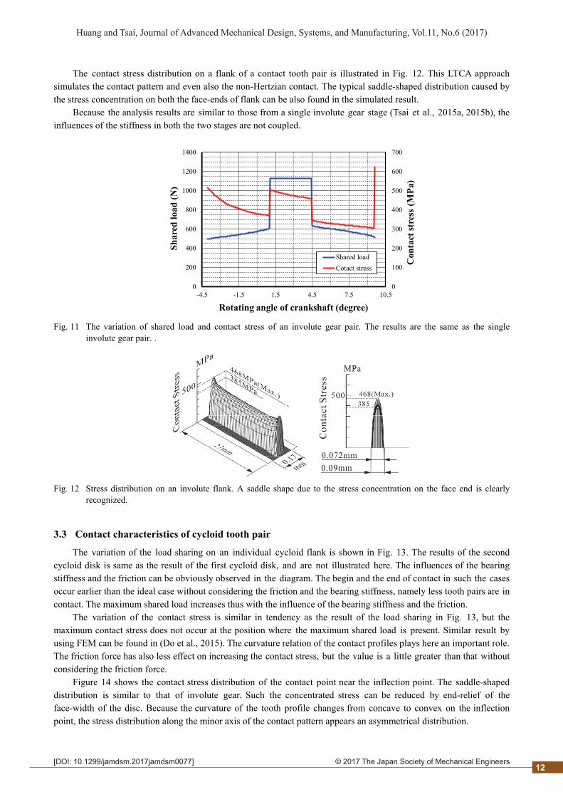
The variation of the load sharing on an individual cycloid flank is shown in Fig. 13. The results of the second cycloid disk is same as the result of the first cycloid disk, and are not illustrated here. The influences of the bearing stiffness and the friction can be obviously observed in the diagram. The begin and the end of contact in such the cases occur earlier than the ideal case without considering the friction and the bearing stiffness, namely less tooth pairs are in contact. The maximum shared load increases thus with the influence of the bearing stiffness and the friction.
The variation of the contact stress is similar in tendency as the result of the load sharing in Fig. 13, but the maximum contact stress does not occur at the position where the maximum shared load is present. Similar result by using FEM can be found in (Do et al., 2015). The curvature relation of the contact profiles plays here an important role. The friction force has also less effect on increasing the contact stress, but the value is a little greater than that without considering the friction force.
Figure 14 shows the contact stress distribution of the contact point near the inflection point. The saddle-shaped distribution is similar to that of involute gear. Such the concentrated stress can be reduced by end-relief of the face-width of the disc. Because the curvature of the tooth profile changes from concave to convex on the inflection point, the stress distribution along the minor axis of the contact pattern appears an asymmetrical distribution.
12
2© 2017 The Japan Society of Mechanical Engineers[DOI: 10.1299/jamdsm.2017jamdsm0077]
Huang and Tsai, Journal of Advanced Mechanical Design, Systems, and Manufacturing, Vol.11, No.6 (2017)
The contact characteristics are also similar to the results from the analysis of a single stage (Tsai et al., 2015a). Because the deformation influences of the crank shaft and the carrier are not involved in the analysis model, the contact characteristics of the cycloid stage in this case are not affected by the stiffness of the involute stage.
0
200
400
600
800
1000
1200
1400
1600
0
0.5
1
1.5
2
2.5
3
3.5
4
-200 -180 -160 -140 -120 -100 -80 -60 -40 -20 0 20
Con
tact
str
ess
CS
[M
Pa]
Loa
d s
har
ing
fact
or L
SF
Rotation angle of the crankshaft [deg]
LSF (ideal)LSF (w/o friction)LSF (w. friction)CS (ideal)CS (w/o friction)CS (w. friction)
AE
Fig. 13 The variation of the load sharing and the contact stress on an individual flank of the cycloid disk. The variation of load sharing factor is strongly influenced by the bearing stiffness and the friction force. On the other hand, the variation of contact stress is mainly influenced by the curvature of the cycloid profile.
Fig.14 The stress distribution of cycloid flank. Similarly as the involute gear flank, a saddle-shaped stress distribution (left) is also recognized clearly. Because the contact position is near the inflection point, the asymmetrical stress distribution along the profile direction (right) is also simulated.
3.4 Displacements due to deformation in the cycloid stage
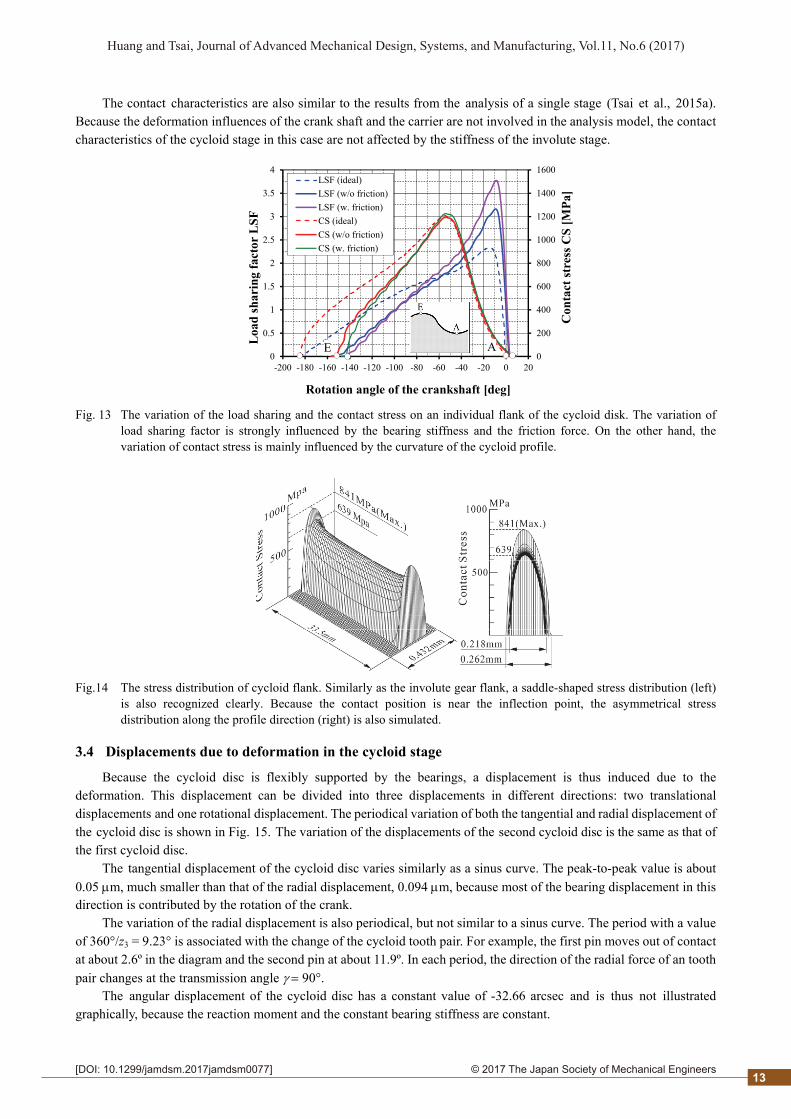
Because the cycloid disc is flexibly supported by the bearings, a displacement is thus induced due to the deformation. This displacement can be divided into three displacements in different directions: two translational displacements and one rotational displacement. The periodical variation of both the tangential and radial displacement of the cycloid disc is shown in Fig. 15. The variation of the displacements of the second cycloid disc is the same as that of the first cycloid disc.
The tangential displacement of the cycloid disc varies similarly as a sinus curve. The peak-to-peak value is about 0.05 m, much smaller than that of the radial displacement, 0.094 m, because most of the bearing displacement in this direction is contributed by the rotation of the crank.
The variation of the radial displacement is also periodical, but not similar to a sinus curve. The period with a value of 360°/z3 = 9.23° is associated with the change of the cycloid tooth pair. For example, the first pin moves out of contact at about 2.6º in the diagram and the second pin at about 11.9º. In each period, the direction of the radial force of an tooth pair changes at the transmission angle 90°.
The angular displacement of the cycloid disc has a constant value of -32.66 arcsec and is thus not illustrated graphically, because the reaction moment and the constant bearing stiffness are constant.
13
2© 2017 The Japan Society of Mechanical Engineers[DOI: 10.1299/jamdsm.2017jamdsm0077]
Huang and Tsai, Journal of Advanced Mechanical Design, Systems, and Manufacturing, Vol.11, No.6 (2017)
1.12
1.14
1.16
1.18
1.2
1.22
1.24
25.24
25.26
25.28
25.3
25.32
25.34
25.36
0 5 10 15 20
Rad
ial d
isp
lace
men
t [
m]
Tan
gen
tial
dis
pla
cem
ent
[m
]
Rotation angle of the cranckshaft [deg]
tangential displacement radial displacement
Fig. 15 The variation of the translational displacements of the cycloid disc. The peak to peak value of the radial displacement is larger than that of the tangential displacement. Both the periodical variations have the same period.
3.5 Displacements due to deformation in the involute stage
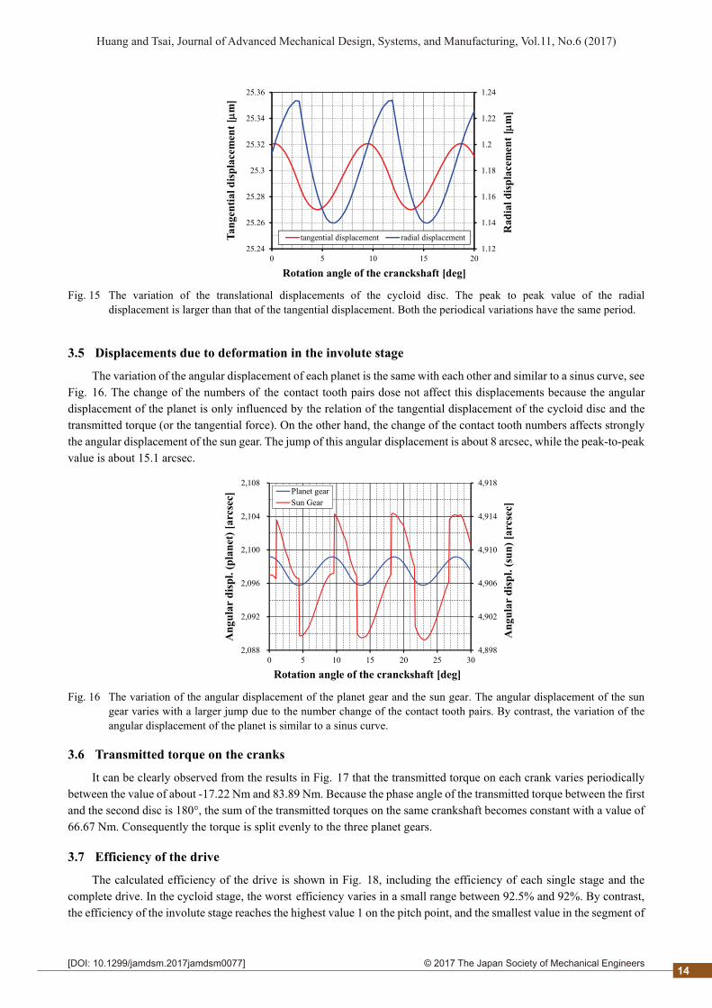
The variation of the angular displacement of each planet is the same with each other and similar to a sinus curve, see Fig. 16. The change of the numbers of the contact tooth pairs dose not affect this displacements because the angular displacement of the planet is only influenced by the relation of the tangential displacement of the cycloid disc and the transmitted torque (or the tangential force). On the other hand, the change of the contact tooth numbers affects strongly the angular displacement of the sun gear. The jump of this angular displacement is about 8 arcsec, while the peak-to-peak value is about 15.1 arcsec.
4,898
4,902
4,906
4,910
4,914
4,918
2,088
2,092
2,096
2,100
2,104
2,108
0 5 10 15 20 25 30
An
gula
r d
isp
l. (s
un
) [a
rcse
c]
An
gula
r d
isp
l. (p
lan
et)
[arc
sec]
Rotation angle of the cranckshaft [deg]
Planet gearSun Gear
Fig. 16 The variation of the angular displacement of the planet gear and the sun gear. The angular displacement of the sun gear varies with a larger jump due to the number change of the contact tooth pairs. By contrast, the variation of the angular displacement of the planet is similar to a sinus curve.
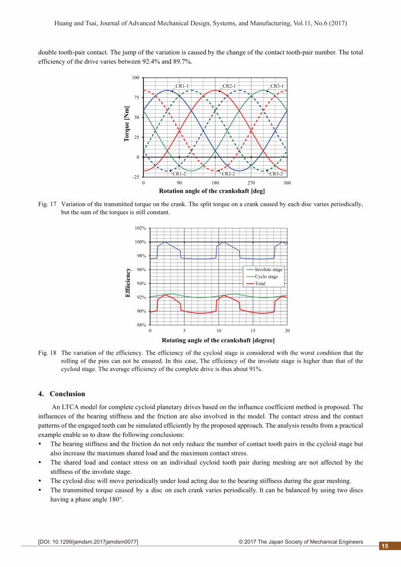
3.6 Transmitted torque on the cranks
It can be clearly observed from the results in Fig. 17 that the transmitted torque on each crank varies periodically between the value of about -17.22 Nm and 83.89 Nm. Because the phase angle of the transmitted torque between the first and the second disc is 180°, the sum of the transmitted torques on the same crankshaft becomes constant with a value of 66.67 Nm. Consequently the torque is split evenly to the three planet gears.
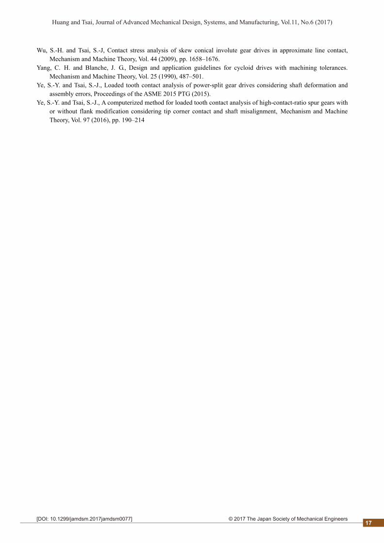
3.7 Efficiency of the drive
The calculated efficiency of the drive is shown in Fig. 18, including the efficiency of each single stage and the complete drive. In the cycloid stage, the worst efficiency varies in a small range between 92.5% and 92%. By contrast, the efficiency of the involute stage reaches the highest value 1 on the pitch point, and the smallest value in the segment of
14
2© 2017 The Japan Society of Mechanical Engineers[DOI: 10.1299/jamdsm.2017jamdsm0077]
Huang and Tsai, Journal of Advanced Mechanical Design, Systems, and Manufacturing, Vol.11, No.6 (2017)
double tooth-pair contact. The jump of the variation is caused by the change of the contact tooth-pair number. The total efficiency of the drive varies between 92.4% and 89.7%.
-25
0
25
50
75
100
0 90 180 270 360
Tor
que
[Nm
]
Rotation angle of the crankshaft [deg]
CR1-1
CR1-2 CR2-2 CR3-2
CR2-1 CR3-1
Fig. 17 Variation of the transmitted torque on the crank. The split torque on a crank caused by each disc varies periodically, but the sum of the torques is still constant.
88%
90%
92%
94%
96%
98%
100%
102%
0 5 10 15 20
Eff
iici
ency
Rotating angle of the crankshaft [degree]
Involute stageCyclo stageTotal
Fig. 18 The variation of the efficiency. The efficiency of the cycloid stage is considered with the worst condition that the rolling of the pins can not be ensured. In this case, The efficiency of the involute stage is higher than that of the cycloid stage. The average efficiency of the complete drive is thus about 91%.
4. Conclusion
An LTCA model for complete cycloid planetary drives based on the influence coefficient method is proposed. The influences of the bearing stiffness and the friction are also involved in the model. The contact stress and the contact patterns of the engaged teeth can be simulated efficiently by the proposed approach. The analysis results from a practical example enable us to draw the following conclusions: The bearing stiffness and the friction do not only reduce the number of contact tooth pairs in the cycloid stage but
also increase the maximum shared load and the maximum contact stress. The shared load and contact stress on an individual cycloid tooth pair during meshing are not affected by the
stiffness of the involute stage. The cycloid disc will move periodically under load acting due to the bearing stiffness during the gear meshing. The transmitted torque caused by a disc on each crank varies periodically. It can be balanced by using two discs
having a phase angle 180°.
15

2© 2017 The Japan Society of Mechanical Engineers[DOI: 10.1299/jamdsm.2017jamdsm0077]
Huang and Tsai, Journal of Advanced Mechanical Design, Systems, and Manufacturing, Vol.11, No.6 (2017)
The average efficiency of the complete cycloid drive in the worst case without rolling of the pins is about 91%, while the average efficiency of the cycloid stage is 92.3%.
The proposed LTCA approach can be extended not only to simulate the contact characteristics of the bearing rollers, but also to involve the influences the deformation of the crankshaft and the carrier, the manufacturing/assembly errors as well as the flank modification in the model additionally.
Acknowledgment
The authors would like to thank Transmission Machinery Co., Ltd. Taiwan and the Ministry of Science and Technology, Taiwan (#105-2221-E-008 -042 -MY3) for their financial support.
References
Blagojevic, M., Marjanovic, N. Djordjevic, Z., Stojanovic, B., A new design of a two-stage cycloidal speed reducer, Journal of Mechanical Design, Vol. 133 (2011) pp. 085001-1–7, DOI:10.1115/1.4004540.
Blanche, J. G. and Yang, C.-H., Cycloid drives with machining tolerances, Journal of Mechanisms, Transmissions, and Automation in Design, Vol. 111 (1989), pp. 337–344.
Do, T. P., Ziegler, P. and Eberhard, P., Review on contact simulation of beveloid and cycloid gears and application of a modern approach to treat deformations, Mathematical and Computer Modelling of Dynamical Systems Vol. 21, No. 4 (2015), pp. 359–388, DOI: 10.1080/13873954.2015.1012838
Dong, X., Deng, J. and Chen, J., Force analysis of RV transmission mechanism, Journal of Shanghai Jiao Tong University, Vol. 30 (1996), pp. 65–70, 84 (in Chinese).
Gorla, C., Davoli, P., Rosa, F., Longoni, C., Chiozzi, F., Samanari, A., Theoretical and experimental analysis of a cycloidal speed reducer. Journal of Mechanical Design, Vol. 130 (2008), pp. 112604-1–8. DOI:10.1115/1.2978342
Hartnett, M.J., Analysis of contact stresses in rolling element bearings, Transactions ASME, Journal of Lubrication Technology, Vol. 101, No. 1 (1979), pp. 105–109.
Hartnett, M. J., General numerical solution for elastic body contact problems, ASME Applied Mechanics Division, AMD, Vol. 39 (1980), pp. 51–66.
Hidaka, T., Wang, H-Y., Ishida, T., Matsumoto, K. and Hashimoto, M., Rotational transmission error of K-H-V-planetary gears with cycloid gear, 1st Report, analytical method of the rotational transmission error. Transactions of JSME, Vol. C60, No. 570 (1994), pp. 645–653 (in Japanese)..
Ishida, T., Hidaka T., Wang, H., Yamada, H. and Hashimoto, M., Bending stress and tooth contact stress of cycloid gear with thin rims.” Transactions of JSME, Vol. C62, No. 593 (1996), pp. 291–297 (in Japanese)..
Kim, Y.-H., Lee, C.-S. and Ahn, H.-S.. Torsional rigidity of a cycloid drive considering finite bearing and Hertz contact stiffness. Proceedings of MPT2009-Sendai, (2009).
Leque, N. D. and Kahraman, A., A three-dimensional load sharing model of planetary gear sets having manufacturing errors, ASME 2015 PTG Conference (2015), paper No. DETC2015-47470.
Li, S., Design and strength analysis methods of the trochoidal gear reducers. Mechanism and Machine Theory. Vol. 81 (2014), pp. 140–154.
Neubauer, B., Otto, M. and Stahl, K., Efficient calculation of load distribution and design of tooth flank modifications in planetary gear systems, VDI-Berichte, Vol. 2255.1 (2015), pp. 549–558.
Schulze, T, Gründer, W., Hartmann-Gerlach, C., Schlecht B., and Senf, M., Load distribution in planetary gears under consideration of all relevant influences. Proceedings of JSME MPT2009-Sendai (2009), pp. 545–550.
Thube, S.V. and Bobak, T.R., Dynamic analysis of a cycloidal gearbox using finite element method. AGMA 12FTM18, (2012).
Tsai S.-J., Huang W.-J. and Huang C.-H., A computerized approach for load analysis of planetary gear drives with epitrochoid-pin tooth-pairs, VDI Berichte Vol. 2255.1 (2015a), pp. 307–317.
Tsai, S.-J., Huang, C.-H., Yeh, H.-Y. and Huang, W.-J., Loaded tooth contact analysis of cycloid planetary gear drive. Proceedings of 14th World Congress in Mechanism and Machine Science (2015b) DOI: 10.6567/IFToMM. 14TH.WC.OS6.014
16
2© 2017 The Japan Society of Mechanical Engineers[DOI: 10.1299/jamdsm.2017jamdsm0077]
Huang and Tsai, Journal of Advanced Mechanical Design, Systems, and Manufacturing, Vol.11, No.6 (2017)
Wu, S.-H. and Tsai, S.-J, Contact stress analysis of skew conical involute gear drives in approximate line contact, Mechanism and Machine Theory, Vol. 44 (2009), pp. 1658–1676.
Yang, C. H. and Blanche, J. G., Design and application guidelines for cycloid drives with machining tolerances. Mechanism and Machine Theory, Vol. 25 (1990), 487–501.
Ye, S.-Y. and Tsai, S.-J., Loaded tooth contact analysis of power-split gear drives considering shaft deformation and assembly errors, Proceedings of the ASME 2015 PTG (2015).
Ye, S.-Y. and Tsai, S.-J., A computerized method for loaded tooth contact analysis of high-contact-ratio spur gears with or without flank modification considering tip corner contact and shaft misalignment, Mechanism and Machine Theory, Vol. 97 (2016), pp. 190–214
17