a study of nitrogen dilution effect on the flammability...
TRANSCRIPT

i
A STUDY OF NITROGEN DILUTION EFFECT ON THE FLAMMABILITY
LIMITS OF METHANE
TENGKU MOHD FADZLI BIN TENGKU AMIN
A thesis submitted to the Faculty of Chemical and Natural Resources
Engineering in partial fulfillment of the requirement for the Degree of Bachelor
of Engineering
in
Chemical Engineering
Faculty of Chemical and Natural Resources Engineering
University Malaysia Pahang
APRIL 2010
v
ABSTRACT
Explosive/Flammability limits data are essential for a quantitative risk
assessment of explosion hazard associated with the use of combustible gas. The
present work is to obtain the fundamental explosive data for prevention of the
hazards in the practical applications. Experiments have been conducted in a constant
volume combustion bomb, and the fuel considered here is natural gas (NG). In this
study, the nitrogen (N2) dilution effects on the flammability limits for pure
hydrocarbons are explored. The effects of nitrogen on NG–air flammability limits
have been investigated. By adding diluents nitrogen (N2) into NG–air mixture, the
dilution effects on the flammability limits have been explored as well, and the results
are plotted as functions of diluents ratio. From the results, it can be conclude that the
range of flammability limits of methane is from 5 vol % until 18 vol %. The effect of
nitrogen dilution on the upper flammability limit of methane observed with the
reduction from 10 vol % to 30 vol % by increasing the vol % of nitrogen.
vi
ABSTRAK
Batas bahan mudah meletup / terbakar data sangat penting untuk penilaian
risiko bahaya letupan kuantitatif berkaitan dengan penggunaan gas yang mudah
terbakar. Karya ini adalah untuk mendapatkan data mendasar letupan untuk
pencegahan bahaya dalam aplikasi praktikal. Percubaan telah dilakukan di bom
pembakaran kelantangan konstan, dan bahan api yang dipertimbangkan di sini adalah
gas alam (NG). Dalam kajian ini, nitrogen (N2) kesan dilusi pada batas hidrokarbon
murni mudah terbakar untuk dieksplorasi. Pengaruh nitrogen terhadap batas mudah
terbakar NG-udara telah diteliti. Dengan menambah nitrogen (N2) ke dalam
campuran NG-udara, kesan penambahan pada batas mudah terbakar telah
dieksplorasi juga, dan keputusan data diplot sebagai fungsi dari nisbah pencair. Dari
keputusan experimen, dapat disimpulkan bahawa batas pembakaran metana adalah
dari 5 % sampai 18 vol % . Pengaruh dilusi nitrogen pada batas atas metana mudah
terbakar diamati dengan penurunan dari 10 % hingga 30 vol % dengan meningkatkan
vol % nitrogen.

vii
TABLE OF CONTENTS
CHAPTER TITLE PAGE
TITLE i
DECLARATION ii
DEDICATION iii
ACKNOWLEDGEMENT iv
ABSTRACT v
ABSTRAK vi
TABLE OF CONTENTS vii
LIST OF TABLE xi
LIST OF FIGURE xii
LIST OF ABBREVIATIONS xiii
LIST OF APPENDIX xiv
1 INTRODUCTION
1.1 Introduction 1
1.1.1 Explosion protection 3
1.1.2 Explosion suppression 3
1.2 Background of study 4
1.3 Problem statement 4
1.4 Objective of study 5
1.5 Scope of study 5

viii
2 LITERATURE REVIEW
2.1 Introduction 6
2.1 Experiment methods 11
2.3 Explosion 12
2.3.1 Explosive and explosive Limits 13
2.3.2 Explosion Pressure 14
2.3.3 Detonation 15
2.4 Explosion Suppression 17
2.4.1 Common suppression 18
2.4.1.1 Inert fire Extinguishing 18
2.4.1.2 Inert gas suppression system 18
2.4.1.3 Argonite 18
2.4.1.4 Carbon dioxide suppression system 19
2.4.1.5 Foam system 19
2.4.1.6 Dry chemical suppression 20
2.5 Previous work 20
2.6 20-L Apparatus 21
3 METHODOLOGY
3.1 Material selection 23
3.1.1 Methane gas 23
3.1.2 Nitrogen 25
3.2 Experiment Apparatus 26
3.2.1 20-L-Apparatus 26
3.2.2 Measurement and Control System
KSEP 332 27
3.3 Experimental condition 27
3.3.1 Pressure and temperature 27
3.3.2 Ignition 28
3.4 Research Parameter 29

ix
3.5 Experiment stages 31
3.5.1 Run the Methane Explosion by Using
Explosion Unit 32
3.5.2 Determine the Methane Lower
Flammability Limit (LFL) and
Upper Explosion Limit (UFL) 32
3.5.3 Cary out methane explosion in the
presence of suppression agent
(Nitrogen gas) 33
3.5.4 Collecting data and Record data 33
3.5.5 Analysis data and make a
Comparison 33
4 RESULTS AND DISCUSSION
4.1 Introduction 34
4.2 Result and discusssion 35
4.2.1 Methane + Air 35
4.2.2 Methane + 10 % nitrogen 37
4.2.3 Methane+ 20 % nitrogen 38
4.2.4 Methan + 30 % nitrogen 39
4.2.5 Graph Pm[bar] vs vol % 40
4.2.6 Graph dP/dt[Bar/s] vs vol % 42
4.3 Comparison data with previous studies 45
5 CONCLUSION AND RECOMMENDATIONS
5.1 Conclusion 46
5.2 Recommendation 47
REFERENCES 48
APPENDIX 50
x
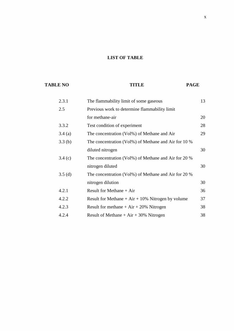
LIST OF TABLE
TABLE NO TITLE PAGE
2.3.1 The flammability limit of some gaseous 13
2.5 Previous work to determine flammability limit
for methane-air 20
3.3.2 Test condition of experiment 28
3.4 (a) The concentration (Vol%) of Methane and Air 29
3.3 (b) The concentration (Vol%) of Methane and Air for 10 %
diluted nitrogen 30
3.4 (c) The concentration (Vol%) of Methane and Air for 20 %
nitrogen diluted 30
3.5 (d) The concentration (Vol%) of Methane and Air for 20 %
nitrogen dilution 30
4.2.1 Result for Methane + Air 36
4.2.2 Result for Methane + Air + 10% Nitrogen by volume 37
4.2.3 Result for methane + Air + 20% Nitrogen 38
4.2.4 Result of Methane + Air + 30% Nitrogen 38
xi
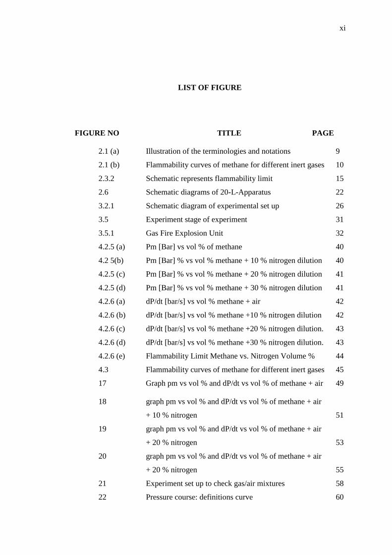
LIST OF FIGURE
FIGURE NO TITLE PAGE
2.1 (a) Illustration of the terminologies and notations 9
2.1 (b) Flammability curves of methane for different inert gases 10
2.3.2 Schematic represents flammability limit 15
2.6 Schematic diagrams of 20-L-Apparatus 22
3.2.1 Schematic diagram of experimental set up 26
3.5 Experiment stage of experiment 31
3.5.1 Gas Fire Explosion Unit 32
4.2.5 (a) Pm [Bar] vs vol % of methane 40
4.2 5(b) Pm [Bar] % vs vol % methane + 10 % nitrogen dilution 40
4.2.5 (c) Pm [Bar] % vs vol % methane + 20 % nitrogen dilution 41
4.2.5 (d) Pm [Bar] % vs vol % methane + 30 % nitrogen dilution 41
4.2.6 (a) dP/dt [bar/s] vs vol % methane + air 42
4.2.6 (b) dP/dt [bar/s] vs vol % methane +10 % nitrogen dilution 42
4.2.6 (c) dP/dt [bar/s] vs vol % methane +20 % nitrogen dilution. 43
4.2.6 (d) dP/dt [bar/s] vs vol % methane +30 % nitrogen dilution. 43
4.2.6 (e) Flammability Limit Methane vs. Nitrogen Volume % 44
4.3 Flammability curves of methane for different inert gases 45
17 Graph pm vs vol % and dP/dt vs vol % of methane + air 49
18 graph pm vs vol % and dP/dt vs vol % of methane + air
+ 10 % nitrogen 51
19 graph pm vs vol % and dP/dt vs vol % of methane + air
+ 20 % nitrogen 53
20 graph pm vs vol % and dP/dt vs vol % of methane + air
+ 20 % nitrogen 55
21 Experiment set up to check gas/air mixtures 58
22 Pressure course: definitions curve 60
xii
LIST OF ABBREVIATIONS
NG Natural gas
CH4
Methane
N2 Nitrogen
CO2 Carbon Dioxide
Vol% Volume percent
STP Standard temperature pressure
Pexp Explosion pressure
t1 Ignition time
dP/dt Rate of pressure rise
(dP/dt)max Max. rate of pressure rise
Kmax Product specific constant
LFL Lower Flammability Limit
UFL Upper Flammability Limits
Pm [bar] Pressure maximum

xiii
LIST OF APPENDICES
APPENDIX TITLE PAGE
A Data from computer 50
B Manual of 20-L-Apparatus 58
C Technical Data of 20-L-Sphere 63
CHAPTER 1
INTRODUCTION
1.1 Introduction
Knowledge of the flammability limits of gaseous mixtures is important for
the safe and economic operation of many industrial and domestic applications that
produce or use flammable mixtures. Flammability limits indicates the region of fuel–
air mixture ratios within which flame propagation can be possible while outside that
flame cannot propagate. There are two distinct separate flammability limits for a
mixture which are lean limit or lower flammability limits (LFL) and rich limit or
upper flammability limit (UFL) (S.Y. Liao, 2005). In other words, combustion will
take place and be self-sustaining only if fuel and air are mixed within the upper and
lower flammability limits. Flammability limits have been discussed extensively in
the combustion literature. There are several criteria to determine the flammability
limits. A successful attempt can be determined by one or a combination of the
following criteria: (1) inspection of the visualization of the flame kernel produced by
the spark, namely visual criterion, and (2) measurements of pressure or temperature
histories in the vessel and appropriate pressure or temperature rise criteria can be
used to designate flammability rather than the purely visual observation of flame
development.

2
Basically, a successful ignition would induce a rapid pressure increase and
temperature rise within a short time, as well as produce a propagating flame front
that could be readily observed. Previous gas flammability limits data were obtained
mainly in flammability tubes, in those tests, a gas mixture in a vertical tube was
ignited and flame propagation was inspected by a visual criterion. The wall
quenching has a significant effect on the flammability measurement in flammability
tube. The larger size of combustion charmer can minimize wall effects and can allow
for the potential use of stronger igniters to ensure the absence of ignition limitations,
so most of the flammability measurements are conducted in closed chambers
recently. And more attentions are being given to the effects of environmental
parameters, such as the vessel size, initial temperature and pressure on the
fundamental characteristics. Moreover, the theoretical studies are carried out for
providing analytical predictions about the flammability limits. With the growing
crisis of energy resources and the strengthening of pollutant legislations, the use of
natural gas (NG) as an alternative fuel has been promoted recently; natural gas is
being regarded as one of the most promising alternative fuels for industrial and
domestic applications. The chemical composition of natural gas varies from field to
field, but the main chemical component of natural gas is believed to be methane.
There is a large volume of flammability limits data available for fuels, such as
methane, ethane, propane, butane, etc. But to the best of our knowledge, no work has
been reported so far on the flammability limits of NG–air mixture.
Therefore, the present work is promoted purposely. The experiments are
made systematically to determine the flammability limits of NG–air mixture in a
constant volume combustion bomb, using conventional spark ignition system. The
explosion pressure traces are recorded and an appropriate pressure rise criterion is
used to define the flammability limits.

3
1.1.1 Explosion Protection
Explosion protection is used to protect all sorts of buildings and civil
engineering infrastructure against internal and external explosions or deflagrations. It
was widely believed until recently that a building subject to an explosive attack had a
chance to remain standing only if it possessed some extraordinary resistive capacity.
This belief rested on the assumption that the specific impulse or the time integral of
pressure, which is a dominant characteristic of the blast load, is fully beyond our
control. Avoidance will make it impossible for an explosion or deflagration to occur,
for instance by means of consistent displacement of the O2 necessary for an
explosion or deflagration to take place, by means of padding gas ( CO2 or N2), or, by
means of keeping the concentration of flammable content of an atmosphere
consistently below or above the explosive limit, or, by means of consistent
elimination of ignition sources. Constructional explosion protection aims at pre-
defined, limited or zero damage that results from applied protective techniques in
combination with reinforcement of the equipment or structures that must be expected
to become subject to internal explosion pressure and flying debris or external violent
impact.
1.1.2 Explosion Suppression
Explosion suppression provided a method for extinguishing a growing
fireball and relies on early detection of an incipient explosion. This is most
commonly achieved by „set-point‟ pressure detection.
Explosion suppression is often used it is not possible to protect by
containment or explosion relief venting and particular where the pressure and flame
of the explosion cannot be vented to a safe location. Explosion suppression is
particularly important is cases where loss of process containment could cause the
emission of toxic dust or other substances harmful to the people or surroundings.

4
1.2 Background of Study
This project is mainly focuses on the suppression system as the main
alternative to prevent or mitigate explosion from occur especially in industrial.
According to National Fire Protection Association (NFPA), the grouping that might
be considered „industrial‟ are basic industry, utilities, manufacturing and many of the
storage properties, NFPA statistics for the 1990 (Karter, 1991) indicate that there
were 22,000 fires and explosion in the combined categories of basic industry, utilities
and manufacturing. An additional 39,500 fires and explosion in the storage properties
are also recorded. (Zalosh, 2002)
Early detection and protection system are very important to be considering in
every industry in order to prevent fires and explosion from occur. In this project, the
Nitrogen gas as the suppression agent will apply to the explosion to test and
determine the effect to the explosion limit. As the fuel source, natural gas (NG) will
be use due to its properties and potential in the occurrence of explosion.
1.3 Problem Statement
Nowadays many an explosion protection system especially in the process
industries as a explosion prevention especially in industries. But there are some
disadvantage of some method is the potential of the suppression agent to mitigate the
explosion limit especially when dealing with hydrogen and methane, in addition
some suppression agent is expensive. There are many methods to prevent fire and
explosion such as isolating, venting and suppression. Venting is system release
pressure indoor or closed system, especially when dealing with LPG, natural gas and
hydrogen where they are high velocity combustion speed and greatest flammable, so
its need early method is suppression by using inert gas such as helium, carbon
dioxide, nitrogen or argon, in this research, nitrogen is used as a suppression agent,
where nitrogen gas is cheaper and easy to get.

5
1.4 Objectives of Study
The objectives of this study are:
i. To determine the flammability limit of natural gas dilute nitrogen gas
mixture in a combustion bomb at atmospheric pressure and ambient
temperature.
ii. To determine the effect of nitrogen suppressing on flammability limit of
premixed natural gas-air mixture in a combustion bomb at atmospheric
pressure and ambient temperature.
1.5 Scope of Study
This study is conducted to determine the flammability limits of premixed
fuel-air-nitrogen mixture in a constant volume spherical vessel with a volume of 20 L
by using conventional spark ignition system which is located at the centre of the
vessel.
In this study methane with 96 % purity is used to replace the natural gas.
Methane can be used to indicate the properties of natural gas since the major
component in natural gas is methane.
The lower flammability limit (LFL) and upper flammability limit (UFL) of
natural gas-air mixture were determined at concentration from 3 vol % to 18 vol %.
The effect of nitrogen in natural gas-air mixture was investigated at nitrogen
enrichment up 30 vol % nitrogen of fuel by at methane concentration from 3 vol % to
18 vol %.
CHAPTER 2
LITERATURE REVIEW
2.1 Introduction
Knowledge of the flammability limits of gaseous mixtures is important for
the safe and economic operation of many industrial and domestic applications that
produce or use flammable mixtures.
Flammable limits apply generally to vapors and are defined as the
concentration range in which a flammable substance can produce a fire or explosion
when an ignition source (such as a spark or open flame) is present. The concentration
is generally expressed as percent fuel by volume. When the combustion of the fuel is
not controlled within the confines of a burner system, the limits of flammability can
be called the explosive limits. There are two distinct separate flammability limits for
a mixture which are lean limit or lower flammability limit (LFL) and rich limit or
upper flammability limit (UFL):
i. Above the upper flammable limit (UFL) the mixture of substance and
air is too rich in fuel (deficient in oxygen) to burn. This is sometimes
called the upper explosive limit (UEL).
ii. Below the lower flammable limit (LFL) the mixture of substance and
air lacks sufficient fuel (substance) to burn. This is sometimes called
the lower explosive limit (LEL).

7
In other words, combustion or explosion will take place and be self-
sustaining only if fuel and air are mixed within the upper and lower flammability
limits. Usually the LFL and UFL of a combustible material are expressed in volume
percentage (vol %) in the literature; however, as the hydrocarbon gas could be taken
as an ideal gas at atmospheric pressure, LFL and UFL could be also explained as the
molar fraction, which is the expression adopted in this study. To avoid misleading
the meaning in formulation, three terminologies are defined here:
i. Fuel mixture the mixture composed of hydrocarbon and air (no inert
gas)
ii. Blended gas the mixture composed of hydrocarbon and inert carbon
dioxide (no air)
iii. Total mixture-the mixture composed of the blended gas and air.
Many manufacturing processes involve flammable chemicals, and an accident
involving a fire or an explosion can occur in storage or process equipment if a
flammable chemical exists inside it or if a loss of containment of flammable
chemicals occurs. Because the gas mixture of a flammable substance could be ignited
only if he concentration of the flammable substance lied within a given range known
as the flammability limits, the flammability limits are one of the important features in
the development of safe practices for handling a flammable vapour or gas. For this
reason, they constitute a crucial issue in research on processing and storing
flammable chemicals safely. In the literature, different methods have been proposed
to predict the flammability limits of a flammable chemical, especially the lower
flammability limit (LFL) of a pure flammable chemical. Industry works with
mixtures under many situations, for example, in a reactor or in a distillation column.
The Le Chatelier equation is widely adopted to estimate the flammability
limits of a mixture composed of flammable gases. However, complex mixtures
composed of flammable gases and non-flammable gases are also formed in process
industries, for example, the inerting procedure. Inerting is the process of adding an
inert gas to a combustible mixture to reduce the concentration of oxygen below the
limiting oxygen concentration (LOC) for the purpose of lowering the likelihood of

8
explosion. In process industries, the inert gas is usually nitrogen or carbon dioxide,
although sometimes steam may be used. As the inert gas does not take part in the
reaction mechanism, the method of “calculated adiabatic flame temperatures” is
usually applied to estimate the flammability limits of a mixture of fuel and inert gas
in the literature Vidal et al .
According to LeChatelier‟s rule:
(2.1)
Where LFL is the lower flammability limit of mixture (vol. %), Ci the
concentration of component i in the gas mixture on an air-free basis (vol. %), and
LFLi is the lower flammability limit for component i (vol %).
Inert gas could be obtained. However, prediction models based on adiabatic
flame temperature theories typically produce satisfactory results in forecasting LFL,
but this is not the case in predicting the upper flammability limit (UFL). Because the
procedure of diluting a combustible gas with inert gas could be also taken as a
mixing process of flammable gas and inert gas, Kondo et al. have attempted to
modify the Le Chatelier equation so that it could be extended to the case of a mixture
of flammable gases and inert gases. The following assumptions were included in
their work:
i. At LFL, the heat of combustion per mole of a mixture composed of fuel
gas and inert gas is equal to the heat of combustion per mole of pure fuel
gas times the molar fraction of the fuel gas in the mixture (i.e., adding
inert gas to fuel gas does not change the reaction mechanism at LFL). The
heat release is the same for all limit mixtures at LFL.
ii. The fuel gas would react completely when combustion takes place at LFL
iii. At UFL, the ratio of the number of moles of oxygen required to burn one
mole of the mixture of fuel gas and inert gas to the number of moles of
9
oxygen required to burn one mole of pure fuel gas equals the molar
fraction of the fuel gas in the mixture (i.e., adding the inert gas to the fuel
gas does not change the reaction mechanism at UFL)
iv. Oxygen would react completely when combustion takes place at UFL.
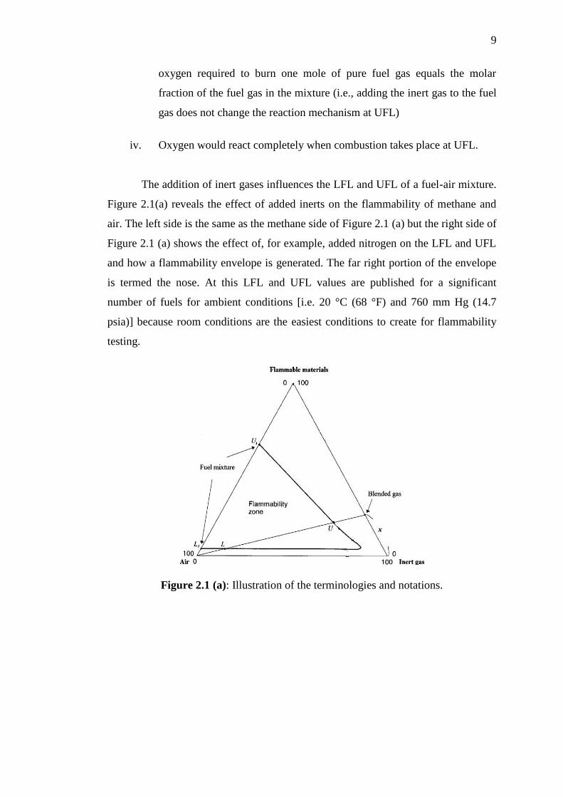
The addition of inert gases influences the LFL and UFL of a fuel-air mixture.
Figure 2.1(a) reveals the effect of added inerts on the flammability of methane and
air. The left side is the same as the methane side of Figure 2.1 (a) but the right side of
Figure 2.1 (a) shows the effect of, for example, added nitrogen on the LFL and UFL
and how a flammability envelope is generated. The far right portion of the envelope
is termed the nose. At this LFL and UFL values are published for a significant
number of fuels for ambient conditions [i.e. 20 °C (68 °F) and 760 mm Hg (14.7
psia)] because room conditions are the easiest conditions to create for flammability
testing.
Figure 2.1 (a): Illustration of the terminologies and notations.

10
As Figure 2.1(b) shows, the change in UFL is usually more obvious than that
in LFL when the inert gas is added, It could be found in Figure 2.1 (b) that when the
concentration of inert gas is low, the LFL of the methane/inert gas mixture will
increase as the concentration of the inert gas increases if the inert gas is carbon
dioxide or steam; the LFL of methane/inert gas mixture seems to be irrelative of the
concentration of inert gas if the inert gas is nitrogen; and the LFL of methane/inert
gas mixture will decrease as the concentration of inert gas increases if the inert gas is
helium.
Figure 2.1 (b): Flammability curves of methane for different inert gases.

11
2.2 Experimental Methods
The standardized measurements of flammability limits are usually conducted
in the flammability tubes or closed vessels. There are several criteria to determine
the flammability limits. A successful attempt can be determined by one or a
combination of the following criteria:
i. Inspection of the visualization of the flame kernel produced by the spark,
namely visual criterion
ii. Measurements of pressure or temperature histories in the vessel and
appropriate pressure or temperature rise criteria can be used to designate
flammability rather than the purely also observation of flame
development
A successful ignition would induce a rapid pressure increase and temperature
rise within a short time as well as produce a propagating flame front that could be
readily observed. Previous gas flammability limit data were obtained mainly in
flammability tubes which in those test a gas mixture in a vertical tube was ignited
and flame propagation was inspected by visual criterion. However, the wall
quenching has a significant effect on the flammability measurement in flammability
tube.
Recently, the flammability measurements are conducted in closed chambers.
This is because the larger size of combustion chamber can minimize wall effects and
can allow potential use of stronger igniters to ensure the absence of ignition
limitations (D.M Jiang et al 2005).

12
2.3 Explosion
An explosion is a rapid increase in volume and release of energy in an
extreme manner, usually with the generation of high temperatures and the release of
gases. An explosion creates a shock wave. If the shock wave is a supersonic
detonation, then the source of the blast is called a "high explosive". Subsonic shock
waves are created by low explosives through the slower burning process known as
deflagration.
High explosives are explosive materials that detonate, meaning that the
explosive shock front passes though the material at a supersonic speed. High
explosives detonate with explosive velocity rates ranging from 3,000 to 9,000 meters
per second. They are normally employed in mining, demolition, and military
applications. They can be divided into two explosives classes differentiated by
sensitivity: Primary explosive and secondary explosive. The term high explosive is in
contrast to the term low explosive, which explodes (deflagrates) at a slower rate.
Low explosives are compounds where the rate of decomposition proceeds
through the material at less than the speed of sound. The decomposition is
propagated by a flame front (deflagration) which travels much more slowly through
the explosive material than a shock wave of a high explosive. Under normal
conditions, low explosives undergo deflagration at rates that vary from a few
centimetres per second to approximately 400 meters per second. It is possible for
them to deflagrate very quickly, producing an effect similar to a detonation. This can
happen under higher pressure or temperature, which usually occurs when ignited in a
confined space. A low explosive is usually a mixture of a combustible substance and
an oxidant that decomposes rapidly (deflagration), however they burn slower than a
high explosive which has an extremely fast burn rate. Low explosives are normally
employed as propellants. Included in this group are gun powders and light
pyrotechnics, such as flares and fireworks.
13
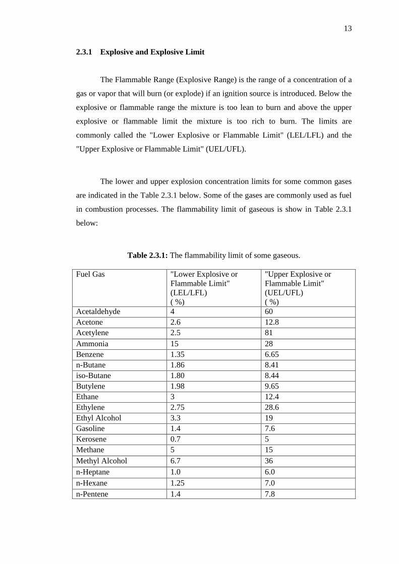
2.3.1 Explosive and Explosive Limit
The Flammable Range (Explosive Range) is the range of a concentration of a
gas or vapor that will burn (or explode) if an ignition source is introduced. Below the
explosive or flammable range the mixture is too lean to burn and above the upper
explosive or flammable limit the mixture is too rich to burn. The limits are
commonly called the "Lower Explosive or Flammable Limit" (LEL/LFL) and the
"Upper Explosive or Flammable Limit" (UEL/UFL).
The lower and upper explosion concentration limits for some common gases
are indicated in the Table 2.3.1 below. Some of the gases are commonly used as fuel
in combustion processes. The flammability limit of gaseous is show in Table 2.3.1
below:
Table 2.3.1: The flammability limit of some gaseous.
Fuel Gas "Lower Explosive or
Flammable Limit"
(LEL/LFL)
( %)
"Upper Explosive or
Flammable Limit"
(UEL/UFL)
( %)
Acetaldehyde 4 60
Acetone 2.6 12.8
Acetylene 2.5 81
Ammonia 15 28
Benzene 1.35 6.65
n-Butane 1.86 8.41
iso-Butane 1.80 8.44
Butylene 1.98 9.65
Ethane 3 12.4
Ethylene 2.75 28.6
Ethyl Alcohol 3.3 19
Gasoline 1.4 7.6
Kerosene 0.7 5
Methane 5 15
Methyl Alcohol 6.7 36
n-Heptane 1.0 6.0
n-Hexane 1.25 7.0
n-Pentene 1.4 7.8

14
2.3.2 Explosion Pressure
Knowledge of pressure-time variation during explosions of fuel-air mixtures
in enclosures is a very important component of safety recommendations for a wide
range of human activities, connected to production, transportation or use of fuels.
The characteristic parameters of a closed vessel explosion are the explosion
pressure, the explosion time and the maximum rate of pressure rise. The explosion
pressure and explosion time were recently defined in the European standard on
maximum explosion pressure determination:
i. The explosion pressure, Pexp is the highest pressure reached during the
explosion in a closed volume at a given fuel concentration
ii. The maximum explosion pressure, Pmax is the highest pressure reached
during a series of explosions of mixtures with varying fuel concentration
iii. The explosion time, exp is the time interval between ignition time and the
moment when the explosion pressure attained
Explosion pressures and explosion times are important for calculating laminar
burning velocities from closed vessel experiments, vent area design, and
characterizing transmission of explosions between interconnected vessels (D. Razus
et al 2006).

15
Based on the pressure time traces three regimes of explosion development or
combustion conversion can be identified. The regimes depend on the initial mixture
composition, at given conditions as illustrated at Figure 2.3.2.below. In the first one,
marked as 1, the pressure increases fast and smoothly to the maximum value, after
ignition. This type of pressure development is seen for near stoichiometric mixtures.
In the second regime, the pressure trace is distinctly S shaped (a shoulder). Such type
of pressure development is a narrow fuel lean concentration range and in a wider
concentration range with fuel rich mixtures. In the third regime the shoulder
disappeared, and the increase is low and slow. (A.A.Pekalski, 2005).
Figure 2.3.2: Schematic represents flammability limit
2.3.3 Detonation
Detonation involves an exothermic front accelerating through a medium that
eventually drives a shock front propagating directly in front of it. They are observed
in both conventional solid and liquid explosives, as well as in reactive gases. The
velocity of detonations in solid and liquid explosives is much higher than that in
gaseous ones, which allows far clearer resolution of the wave system in the latter.

16
Gaseous detonations normally occur in confined systems but are occasionally
observed in large vapour clouds. Again, they are often associated with a gaseous
mixture of fuel and oxidant of a composition, somewhat below conventional
flammability limits. There is an extraordinary variety of fuels that may be present as
gases, as droplet fogs and as dust suspensions. Other materials, such as acetylene,
ozone and hydrogen peroxide are detonable in the absence of oxygen; fuller lists are
given by both Stull and Bretherick. Oxidants include halogens, ozone, hydrogen
peroxide and oxides of nitrogen and chlorine.
In terms of external damage, it is important to distinguish between
detonations and deflagrations where the exothermic wave is subsonic and maximum
pressures are at most a quarter of those generated by the former. Processes involved
in the transition between deflagration and detonation are covered thoroughly by
Nettleton.
The simplest theory to predict the behaviour of detonations in gases is known
as Chapman-Jouguet (CJ) theory, developed around the turn of the 20th century. This
theory, described by a relatively simple set of algebraic equations, models the
detonation as a propagating shock wave accompanied by exothermic heat release.
Such a theory confines the chemistry and diffusive transport processes to an
infinitely thin zone.
A more complex theory was advanced during World War II independently by
Zel'dovich, von Neumann, and W. Doering. This theory, now known as ZND theory,
admits finite-rate chemical reactions and thus describes a detonation as an infinitely
thin shock wave followed by a zone of exothermic chemical reaction. With a
reference frame of a stationary shock, the following flow is subsonic, so that an
acoustic reaction zone follows immediately behind the lead front, the Chapman-
Jouguet condition. Both theories describe one-dimensional and steady wave fronts.
However, in the 1960s, experiments revealed that gas-phase detonations were most
often characterized by unsteady, three-dimensional structures, which can only in an
averaged sense be predicted by one-dimensional steady theories. Indeed, such waves
are quenched as their structure is destroyed.