a study of detection and diagnosis of faults in vlsi
TRANSCRIPT
ISSN:2277-7881; IMPACT FACTOR :6.514(2021); IC VALUE:5.16; ISI VALUE:2.286 Peer Reviewed and Refereed Journal: VOLUME:10, ISSUE:4(1), April:2021
Online Copy Available: www.ijmer.in Digital certificate of publication:http://ijmer.in/pdf/e-Certificate%20of%20Publication-IJMER.pdf
158
A STUDY OF DETECTION AND DIAGNOSIS OF FAULTS IN VLSI TESTING
Dr.Jayapradha.V Assistant Professor, ECE Department,SCSVMV
Kanchipuram,India Abstract
Multiple faults area unit a lot of seemingly to occur within the invented circuits since they need been changing into larger and denser in the past decades. There are researches that propose the ATPG methodology to traumatize double faults by quickly choosing all the undetected faults by the check patterns for the only fault, and so generating the extra check patterns for those undetected faults. This paper deals with the Automatic test pattern generation (ATPG) to measure the faults and discuss about the types of faults and how to detect the various faults in the circuits.
Keywords: ATPG, Stuck-at-Faults, Multiple Stuct-at Faults and Test Compaction. Introduction
As the range of transistors within the circuit is staggeringly increasing, especiallyfor the large-scale circuit, faults measure probably to happen within the circuit. Therefore, the functionality of the circuit must be completely inspected by test patterns. For the benefit of test generation, stuck-at fault is commonly used as afault model at gate level. Moreover, Automatic test Pattern Generation (ATPG) developed to measure all the faults withcompact test patterns. Currently, there exists several ATPG ways which might observeall single stuck-at (SSA) faults.
In case of faults, not solely SSA fault, however conjointly multiple stuck-at (MSA) fault happens within the circuit that is tough to be absolutely covered since the amount of MSA faults is exponentially large. Most of the methodology based on BDD targets for MSA fault [1][2]. Authors [3][4] suggests the fault detecting methods for MSA as parallel vector pair method and genetic algorithm for generating the test patterns. However, all non-redundant faults cannot be detected by the above-mentioned methods. Authors in [5] projected a double stuck-at (DSA) fault ATPG methodology that is on the idea of the SSA take a look at patterns Fault Detection The additional test pattern is required for detecting DSA fault which is not detected by the test patterns of the SSA fault. However, it fails to get compact test patterns which willcover all the faults as a result of some DSA faults are undetected which impacts in execution speed. The author suggests. Improved ATPG methodology supported [5] which may quickly acquire complete test patterns for the DSA fault by analyzing the test patterns for SSA fault.
While detecting and generating a big fault list, the main task to be in concern is MSA faults. Rather than checking of all MSA faults, the author focuses on the undetected ones by way of thetest patterns for SSA. In different words, only the extra test patterns for the undetected MSA faults are generated. And it is difficult to get al faults by observing the whole fault list.
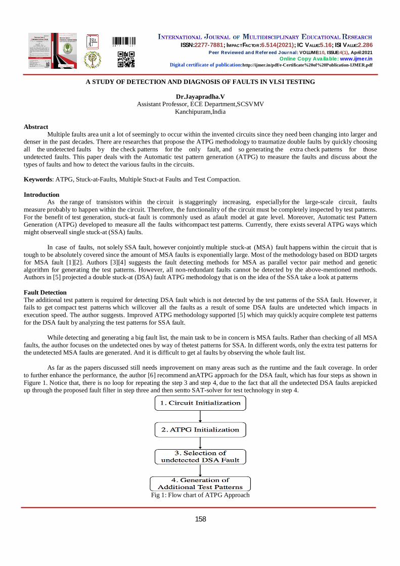
As far as the papers discussed still needs improvement on many areas such as the runtime and the fault coverage. In order to further enhance the performance, the author [6] recommend anATPG approach for the DSA fault, which has four steps as shown in Figure 1. Notice that, there is no loop for repeating the step 3 and step 4, due to the fact that all the undetected DSA faults arepicked up through the proposed fault filter in step three and then sentto SAT-solver for test technology in step 4.
Fig 1: Flow chart of ATPG Approach

ISSN:2277-7881; IMPACT FACTOR :6.514(2021); IC VALUE:5.16; ISI VALUE:2.286 Peer Reviewed and Refereed Journal: VOLUME:10, ISSUE:4(1), April:2021
Online Copy Available: www.ijmer.in Digital certificate of publication:http://ijmer.in/pdf/e-Certificate%20of%20Publication-IJMER.pdf
159
Due to the redundancies or test constraints, the undetectable target faults exist in a circuit, that usually have an effect on faults of different types. [2]. The presence of undetectable target faults ends up in test holes, wherever tests that ought to are included within the test set are missing as a result of the faults they would are generated for undetectable. These leads to undetected test holes around the area of target faults. The author [8] modifies the test procedure for target faults of the static test compaction. This method is applicable to a test set that does no longer have an ample range of unspecified values left to achieve additional take compaction. The author proposed the single stuck-at faults as target faults and the test modified procedure from the previous with gate-exhaustive faults were applied to benchmark circuits.
The Test set T0 is a compact test set for single stuck-at faults. All the single stuck-at faults that are left undetected by T0 are covered in the set [9]. Thus, aborted faults (if there are any) are dealt with comparable to undetectable faults. This is justified by the truth that aborted faults leave test holes similar to undetectable faults.
Test compaction supported with full scan circuit underwent multicycle tests. Multicycle test with a number of clock cycles
between the scan-in and scan-out operations, can able to detect more number of faults than a single- or two-cycle test [10]. Thus, in multicycle tests incorporates with fewer tests will contain the less test set requires fewer scan operations. Although the test set may additionally incorporate more clock cycles between scan operations, scan operations are the essential contributor to the test application time and test records volume. Stuck-At Test
The stuck-at test consists of two faults, the stuck-at-low and the stuck-at-high test. One or a lot of test steps are going to be generated for the stuck-at-low test ♦ all BScan nets have a high level in each test step if possible. Thus, the stuck-at test is separatedfrom the test for shorts and clear identification of the error types is possible. ♦ each drivable pin drives a high level at least one time in the stuck-at-low part and each input andbidirectional pin measures a high level at least one time (real stuck-at test). Pull-up- and Pull-down Resistors
The Pull-up test of net are going to be enclosed within the stuck-at-high test (all nets typically have LOW level). [11]. A tristate step (all BScan pins of this web are high-impedance) are going to be generated once the test at step wherever the various drives a LOW level. the subsequent CaptureDR then expects a HIGH level on these pins.
The tristate step won't essentially be generated at the same time for all Pull-up nets, as this may result in a conflict with the
utmost variety of pins which will switch at constant time.Whether a missing pull-up resistance is detectable during this step, i.e., the missing pull-up resistance changes the measurement, depends on 2 factors: ♦ If the floating level is LOW for a missing pull-up resistance, then the missing pull-up resistance are going to be detected. ♦ If the floating level is HIGH for a missing pull-up resistance, then no distinction are going to be detected statically. Fault diagnosis Interconnection test
Diagnosis will be carried out only if faults occurred as based on the test generation rules. During testing of circuits Netlist File, diagnosis file and error file will be generated, which gives the actual deviations on BScan cell level are going to be used for diagnosis. Based on the values deviation and the expected values of the circuits, the faulty nets will be detected. The diagnosis will be executed in two steps
First step is to search for stuck at errors in pins and nets. Form this list will be prepared and further excluded in step 2. When all the pins measures the same set of values most of the time and the other set a very minimum time is detected as stuct
at error. This concept can be applicable in both input and output pins.
A stuck-at error on associate input pin is detected once this pin for good measures constant level, however another set a minimum of just the once and another input pin of constant netmeasures this alternative level a minimum of just the once.
A stuck-at error on associate output is detected once all input pins for good live constantlevel on activating this output, however the inverse level was to be driven a minimum of just the once and no other stuck-at error of net was detected.

ISSN:2277-7881; IMPACT FACTOR :6.514(2021); IC VALUE:5.16; ISI VALUE:2.286 Peer Reviewed and Refereed Journal: VOLUME:10, ISSUE:4(1), April:2021
Online Copy Available: www.ijmer.in Digital certificate of publication:http://ijmer.in/pdf/e-Certificate%20of%20Publication-IJMER.pdf
160
2. Second step is to search for the shorts between the nets.
Nets containing many input pins and measurement contradictory values that don't seem to be caused by stuck-at errors are going to be divided into their input pins. it's assumed that these pins are separated from the initial net which they need a brief to a different net. a brief is detected if the same level is measured on the various nets altogether testing steps. Conclusion
This paper illustrates the various faults in VLSI testing and shows how it can be occurred in the circuits. The idea is to bringing together this material is to illustrate as wide a range of potential applications as possible and to provide a detection of single stuck at faults and multiple stuct-at faults in the circuits. This gives the clear view of how the test patterns generated during testing is suitable for all types of fault detection and diagnosis. References [1] Czutro, S. M. Reddy, I. Polian, and B. Becker, “Satbased test pattern generation with improved dynamic compaction,” in Proc.
13th Int. Conf. Embedded Syst. 27th Int. Conf. VLSI Design, Jan. 2014, pp. 56–61.
[2] R. Ubar, S. Kostin, and J. Raik, “Multiple stuck-at-fault detection theorem,” in Proc. IEEE 15th Int. Symp. Design Diagnostics Electron. Circuits Syst. (DDECS), Apr. 2012, pp. 236–241.
[3] S. Kajihara, A. Murakami, and T. Kaneko, “On compact test sets for multiple stuck-at faults for large circuits,” in Proc. IEEE ATS, Shanghai, China, Nov. 1999, pp. 20–24.
[4] J. P. Anita and P. T. Vanathi, “Genetic algorithm-based test pattern generation for multiple stuck-at faults and test power reduction in VLSI circuits,” in Proc. Int. Conf. Electron. Commun. Syst. (ICECS), Feb. 2014, pp. 1–6.
[5] Peikun Wang, Conrad Jinyong Moore, Amir Masoud Gharehbaghi, and Masahiro Fujita. "An ATPG Method for Double Stuck-At Faults by Analyzing Propagation Paths of Single Faults." IEEE Transactions on Circuits and Systems I: Regular Papers 65, no. 3 (2018): 1063- 1074.
[6] Peikun Wang, Amir Masoud Gharehbaghi, Masahiro Fujita,”Automatic Test Pattern Generation for Double Stuck-at Faults Based on Test Patterns of Single Faults”,inproc.IEEE20th Int'l Symposium on Quality Electronic Design, 2014, pp 284-290.
[7] F. Hapke and J. Schloeffel,” Introduction to the Defect-oriented Cellaware Test Methodology for Significant Reduction of DPPM Rates”, in Proc. European Test Symp., 2012, pp. 1-6.
[8] I.Pomeranz,” Static Test Compaction for Delay Fault Test Sets Consisting of Broadside and Skewed-Load Tests”, in Proc. VLSI Test Symp., 2011, pp. 84-89.
[9] Irith Pomeranz,”Improving a Test Set to Cover Test Holes by Detecting Gate-Exhaustive Faults”,in proc. IEEE Int'l Symposium on Defect and Fault Tolerance in VLSI and Nanotechnology Systems (DFT), 2020
[10] IrithPomeranz,”Test Compaction by Backward and Forward Extension of Multicycle Tests,” in IEEE Transactions On Very Large Scale Integration (VLSI) Systems, 2020
[11] V.Jayapradha, S.Ravi “Test Coverage For Bscan And Non-Bscan Circuits Using JTAG”, International Journal of Advanced Engineering Technology ISSN E-ISSN 0976-3945 Volume VII/Issue II/April-June,2016.

Filename: 25 Directory: C:\Users\DELL\Desktop\Volume 10, Issue 4, April 2021,IJMER
Articles\Final Issues\4(1) Template: C:\Users\DELL\AppData\Roaming\Microsoft\Templates\Normal.dotm Title: Subject: Author: Windows User Keywords: Comments: Creation Date: 4/16/2021 4:41:00 PM Change Number: 3 Last Saved On: 4/20/2021 11:24:00 PM Last Saved By: Murali Korada Total Editing Time: 13 Minutes Last Printed On: 4/29/2021 2:53:00 PM As of Last Complete Printing Number of Pages: 3 Number of Words: 1,668 (approx.) Number of Characters: 9,509 (approx.)