a strategy for cast part shape design optimisation
TRANSCRIPT
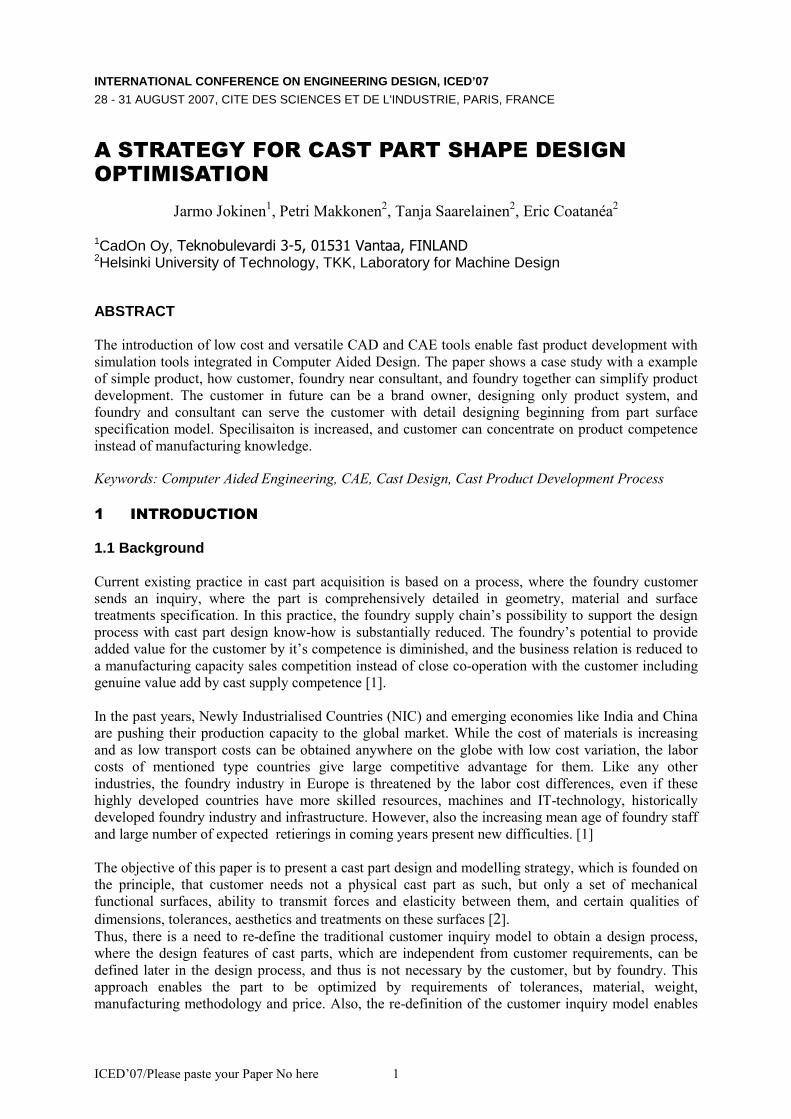
ICED’07/Please paste your Paper No here 1
INTERNATIONAL CONFERENCE ON ENGINEERING DESIGN, ICED’07
28 - 31 AUGUST 2007, CITE DES SCIENCES ET DE L'INDUSTRIE, PARIS, FRANCE
A STRATEGY FOR CAST PART SHAPE DESIGN
OPTIMISATION
Jarmo Jokinen1, Petri Makkonen
2, Tanja Saarelainen
2, Eric Coatanéa
2
1CadOn Oy, Teknobulevardi 3-5, 01531 Vantaa, FINLAND 2Helsinki University of Technology, TKK, Laboratory for Machine Design
ABSTRACT
The introduction of low cost and versatile CAD and CAE tools enable fast product development with
simulation tools integrated in Computer Aided Design. The paper shows a case study with a example
of simple product, how customer, foundry near consultant, and foundry together can simplify product
development. The customer in future can be a brand owner, designing only product system, and
foundry and consultant can serve the customer with detail designing beginning from part surface
specification model. Specilisaiton is increased, and customer can concentrate on product competence
instead of manufacturing knowledge.
Keywords: Computer Aided Engineering, CAE, Cast Design, Cast Product Development Process
1 INTRODUCTION
1.1 Background
Current existing practice in cast part acquisition is based on a process, where the foundry customer
sends an inquiry, where the part is comprehensively detailed in geometry, material and surface
treatments specification. In this practice, the foundry supply chain’s possibility to support the design
process with cast part design know-how is substantially reduced. The foundry’s potential to provide
added value for the customer by it’s competence is diminished, and the business relation is reduced to
a manufacturing capacity sales competition instead of close co-operation with the customer including
genuine value add by cast supply competence [1].
In the past years, Newly Industrialised Countries (NIC) and emerging economies like India and China
are pushing their production capacity to the global market. While the cost of materials is increasing
and as low transport costs can be obtained anywhere on the globe with low cost variation, the labor
costs of mentioned type countries give large competitive advantage for them. Like any other
industries, the foundry industry in Europe is threatened by the labor cost differences, even if these
highly developed countries have more skilled resources, machines and IT-technology, historically
developed foundry industry and infrastructure. However, also the increasing mean age of foundry staff
and large number of expected retierings in coming years present new difficulties. [1]
The objective of this paper is to present a cast part design and modelling strategy, which is founded on
the principle, that customer needs not a physical cast part as such, but only a set of mechanical
functional surfaces, ability to transmit forces and elasticity between them, and certain qualities of
dimensions, tolerances, aesthetics and treatments on these surfaces [2]. Thus, there is a need to re-define the traditional customer inquiry model to obtain a design process,
where the design features of cast parts, which are independent from customer requirements, can be
defined later in the design process, and thus is not necessary by the customer, but by foundry. This
approach enables the part to be optimized by requirements of tolerances, material, weight,
manufacturing methodology and price. Also, the re-definition of the customer inquiry model enables
ICED’07/Please paste your Paper No here 2
to re-organise customer foundry design process: With a neutral format inquiry specification model the
foundry can concentrate on further development of the cast part with it’s own native cast design
analysis software, which in this case is demonstrated with Solid Works.
1.2 Objectives
The design process on single part level is based on the principle, that part design begins from the
specification of functional surfaces, the function carriers. The functionally specified boundaries
contact with other parts. In the specifying geometry, the size, distances and tolerances are determined
as also the surface roughness and surface treatments. Thus, the customer of a part manufacturer, i.e.
foundry, should not specify more than what is required for the functional surfaces. More over, the
functional surfaces must be able to transmit the loads between the load carrying surfaces. The
customer’s needs for functional surfaces are determined and fixed, while the load carrying features are
not. The dimensioning for the load carrying features can be optimized later. Thus, the specification is
possible to be created with any CAD-system capable to output neutral file format.
The part manufacturer in the foundry can then continue from the customer - foundry standard interface
with their own native file format and design the part topology and dimensions with respect to
optimization criteria concerning weight, stiffness, strength, material, and in-house manufacturing
resources. The full capacity of the foundry’s design competence can be utilized, and the foundry can
be integrated to the customers manufacturing process as an independent partner with design
responsibility.
2 STATE OF THE ART
To maintain their position at the front edge of the foundry branch, European companies have obtained
many tools to serve their customers with high quality castings. The key issue, which foundries have to
face is, that a cast is not a product. To maintain the competitive edge, foundries must integrate their
processes with the customer product development process, rather than letting the customer to do the
design and preliminary production planning for the product.
The foundries must therefore change their focus from their physical cast products to service concepts,
including design support from the beginning of the life cycle to end of it. This paper focuses on the
design phase of the cast. The previous paper concentrate on the design service interface from the
beginning of the design to cast order specification. Coming papers will continue from this on. It is also
evident, that the earlier the manufacturing specialists can consult the designer, the easier
manufacturing process can still be reconsidered and thus the manufacturing cost, efficiency and other
downstream decisions can be left for manufacturing specialists to reduce cost and supply time.
The research on computer support tools in 3industry has been based on many different kinds of approaches. This literary study was performed based on search from El Compendex Web database
with recent CAD/CAM/CAE publications on cast CAE:
� Knowledge based expert systems for manufacturing have been presented by Er & Dias,
where the casting alloy, geometric complexity, casting accuracy production quantity and
comparative costs can be considered [4], � Recognition of form features for casting is based either on interactive feature definition,
where the features are defined from the geometric description of the designer, or the
model is build by a set of specific form features selected from a pre-created library. The
manufacturing aspects are created from a set of transformations compatible to the selected
manufacturing process. In feature extraction method, the features are extracted from a
solid model to create the model of the object. The model is then submitted to a process
that attempts to recognise the shape features of the object relevant for the technical
detailing. [5], [6]. A knowledge based system has been developed identifying nine types
of die design components, boss, plate, wall hole, ribs and other features [7].
ICED’07/Please paste your Paper No here 3
� Database approaches for selection of materials and manufacturing process [8]. � Assistance tools for cast planning, like feeder and runner systems designing, based on
material databases, optimisation and genetic algorithms. Hu et al. have studied magnesium
telecommunication parts’ manufacturing with two types of gating system and analysed the
swirling flow points and last filled areas and compared them to numerical analysis.
[9],[10], [11] � Studies and tools for separating objects from tools and definition planning tools for
division planes of casts. Ahn et al. have studied the geometrical problem separating a cast
to two opposite directions without the divided geometry to colliding each other or a other
cast part. [12] � CAD/CAE systems for castings. Zhang and Xiong have developed a CAD system for
designing the runner and gating systems according the characteristics of die-casting
machine, the casting geometry and the properties of the alloy. The CAD system makes the
basic dimensioning of the casting and die based on basic calculations. The CAE system is
capable to analyse the thermal and flow field. [13] � Determination of castability by geometry. An approach similar to Ahn et al., Bose et. al.
have studied and developed a simple algorithm in the time of problem complexity of
n2logn. Also a more complicated algorithm has been developed. [14]
� CAD integrated RP and LOM-method. Alain Bernard et al. have carried out a study based
on tool manufacturing with rapid prototyping process. The created system allowed to
study the usability of the tool and allowed to diminish the wall thickness to 4 mm. [15] � Cast filling and solidification simulation tools. Zhang et al. have developed a finite
element method for analysing with volume of fluid method for 3D-castings with thin-
walled cavities. [16]
� Dimensionless approaches for cast life cycle analysis. [17] � Yue et. al. have developed a database approach for die casting expert system to be used
together with Pro/Engineer CAD software and MAGMASOFT simulation software. [18]
3. METHODOLOGY
The customer – foundry service interface technology is described in a earlier paper
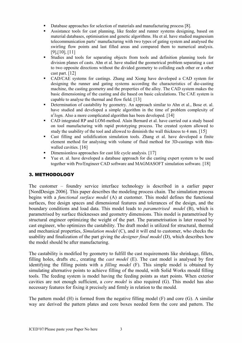
[NordDesign 2006]. This paper describes the modeling process chain. The simulation process
begins with a functional surface model (A) at customer. This model defines the functional
surfaces, free design spaces and dimensional features and tolerances of the design, and the
boundary conditions and load data. This model leads to parametrised model (B), which is
parametrised by surface thicknesses and geometry dimensions. This model is parametrised by
structural engineer optimizing the weight of the part. The parametrisation is later reused by
cast engineer, who optimizes the castability. The draft model is utilized for structural, thermal
and mechanical properties, Simulation model (C), and it will end to customer, who checks the
usability and finalization of the part giving the designer final model (D), which describes how
the model should be after manufacturing.
The castability is modified by geometry to fulfill the cast requirements like shrinkage, fillets,
filling holes, drafts etc., creating the cast model (E). The cast model is analysed by first
identifying the filling points with a filling model (F). This simple model is obtained by
simulating alternative points to achieve filling of the mould, with Solid Works mould filling
tools. The feeding system is model having the feeding points as start points. When exterior
cavities are not enough sufficient, a core model is also required (G). This model has also
necessary features for fixing it precisely and firmly in relation to the mould.
The pattern model (H) is formed from the negative filling model (F) and core (G). A similar
way are derived the pattern plates and core boxes needed form the core and pattern. The
ICED’07/Please paste your Paper No here 4
system is simulated with model simulation containing filling, freezing and puriosity
simulations (I)
Fig. 1. CAE-tool driven product development of cast parts. Dotted lines show feedback iteration.
4. SIMULATION DRIVEN CAST PART OPTIMISATION
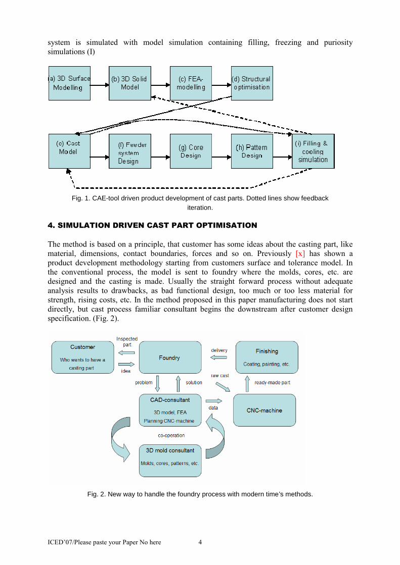
The method is based on a principle, that customer has some ideas about the casting part, like
material, dimensions, contact boundaries, forces and so on. Previously [x] has shown a
product development methodology starting from customers surface and tolerance model. In
the conventional process, the model is sent to foundry where the molds, cores, etc. are
designed and the casting is made. Usually the straight forward process without adequate
analysis results to drawbacks, as bad functional design, too much or too less material for
strength, rising costs, etc. In the method proposed in this paper manufacturing does not start
directly, but cast process familiar consultant begins the downstream after customer design
specification. (Fig. 2).
Fig. 2. New way to handle the foundry process with modern time’s methods.
ICED’07/Please paste your Paper No here 5
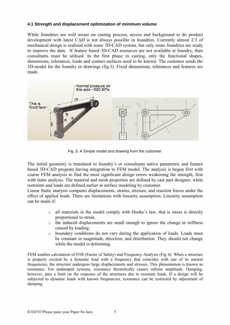
4.1 Strength and displacement optimization of minim um volume
While foundries are well aware on casting process, access and background to do product
development with latest CAD is not always possible in foundries. Currently almost 2/3 of
mechanical design is realized with some 3D-CAD system, but only some foundries are ready
to improve the data. If feature based 3D-CAD resources are not available at foundry, then
consultants must be utilised. In the first phase in casting, only the functional shapes,
dimensions, tolerances, loads and contact surfaces need to be known. The customer sends the
3D-model for the foundry or drawings (fig.3). Fixed dimensions, tolerances and features are
made.
Fig. 3. A Simple model and drawing from the customer.
The initial geometry is translated to foundry’s or consultants native parametric and feature
based 3D-CAD program having integration to FEM model. The analysis is begun first with
coarse FEM analysis to find the most significant design errors weakening the strength, first
with static analysis. The material and mesh properties are defined by cast part designer, while
restraints and loads are defined earlier in surface modeling by customer.
Linear Static analysis computes displacements, strains, stresses, and reaction forces under the
effect of applied loads. There are limitations with linearity assumption. Linearity assumption
can be made if:
o all materials in the model comply with Hooke’s law, that is stress is directly
proportional to strain.
o the induced displacements are small enough to ignore the change in stiffness
caused by loading.
o boundary conditions do not vary during the application of loads. Loads must
be constant in magnitude, direction, and distribution. They should not change
while the model is deforming.
FEM enables calculation of FOS (Factor of Safety) and Frequency Analysis (Fig 4). When a structure
is properly excited by a dynamic load with a frequency that coincides with one of its natural
frequencies, the structure undergoes large displacements and stresses. This phenomenon is known as
resonance. For undamped systems, resonance theoretically causes infinite amplitude. Damping,
however, puts a limit on the response of the structures due to resonant loads. If a design will be
subjected to dynamic loads with known frequencies, resonance can be restricted by adjustment of
damping.
ICED’07/Please paste your Paper No here 6
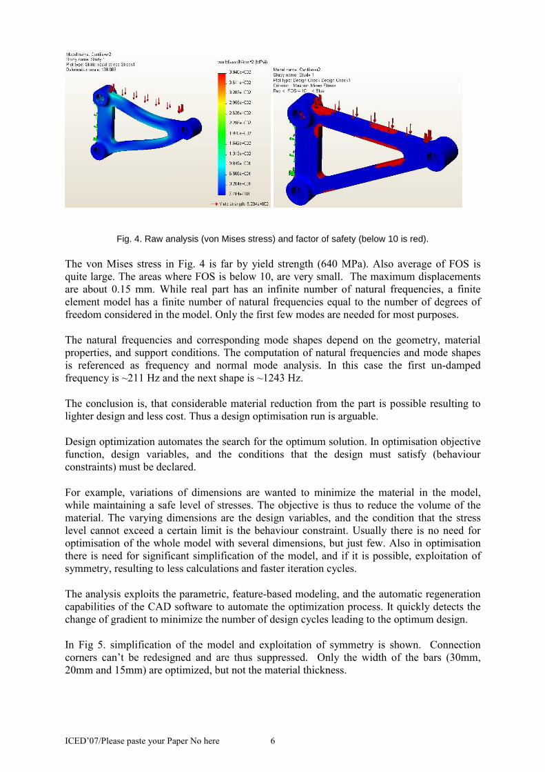
Fig. 4. Raw analysis (von Mises stress) and factor of safety (below 10 is red).
The von Mises stress in Fig. 4 is far by yield strength (640 MPa). Also average of FOS is
quite large. The areas where FOS is below 10, are very small. The maximum displacements
are about 0.15 mm. While real part has an infinite number of natural frequencies, a finite
element model has a finite number of natural frequencies equal to the number of degrees of
freedom considered in the model. Only the first few modes are needed for most purposes.
The natural frequencies and corresponding mode shapes depend on the geometry, material
properties, and support conditions. The computation of natural frequencies and mode shapes
is referenced as frequency and normal mode analysis. In this case the first un-damped
frequency is ~211 Hz and the next shape is ~1243 Hz.
The conclusion is, that considerable material reduction from the part is possible resulting to
lighter design and less cost. Thus a design optimisation run is arguable.
Design optimization automates the search for the optimum solution. In optimisation objective
function, design variables, and the conditions that the design must satisfy (behaviour
constraints) must be declared.
For example, variations of dimensions are wanted to minimize the material in the model,
while maintaining a safe level of stresses. The objective is thus to reduce the volume of the
material. The varying dimensions are the design variables, and the condition that the stress
level cannot exceed a certain limit is the behaviour constraint. Usually there is no need for
optimisation of the whole model with several dimensions, but just few. Also in optimisation
there is need for significant simplification of the model, and if it is possible, exploitation of
symmetry, resulting to less calculations and faster iteration cycles.
The analysis exploits the parametric, feature-based modeling, and the automatic regeneration
capabilities of the CAD software to automate the optimization process. It quickly detects the
change of gradient to minimize the number of design cycles leading to the optimum design.
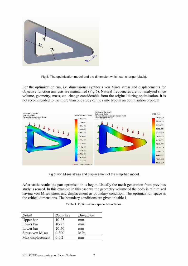
In Fig 5. simplification of the model and exploitation of symmetry is shown. Connection
corners can’t be redesigned and are thus suppressed. Only the width of the bars (30mm,
20mm and 15mm) are optimized, but not the material thickness.
ICED’07/Please paste your Paper No here 7
Fig 5. The optimization model and the dimension which can change (black).
For the optimization run, i.e. dimensional synthesis von Mises stress and displacements for
objective function analysis are maintained (Fig 6). Natural frequencies are not analysed since
volume, geometry, mass, etc. change considerable from the original during optimisation. It is
not recommended to use more than one study of the same type in an optimisation problem
Fig 6. von Mises stress and displacement of the simplified model.
After static results the part optimisation is begun. Usually the mesh generation from previous
study is reused. In this example in this case we the geometry volume of the body is minimized
having von Mises stress and displacement as boundary condition. The optimization space is
the critical dimensions. The boundary conditions are given in table 1.
Table 1. Optimisation space boundaries.
Detail Boundary Dimension
Upper bar 10-25 mm
Lower bar 10-25 mm
Lower bar 20-50 mm
Stress von Mises 0-300 MPa
Max displacement 0-0.2 mm
ICED’07/Please paste your Paper No here 8
In optimization, a the task is to minimize goal function g(x) with subject of constraints
nmmnjxk
nixh
j
i
≥=≥==
;,,0)(
..1,0)( (1)
Here, the goal function is formed from geometrical dimensions as parameters for g(x), and
k(x) forms the behaviour constraints.
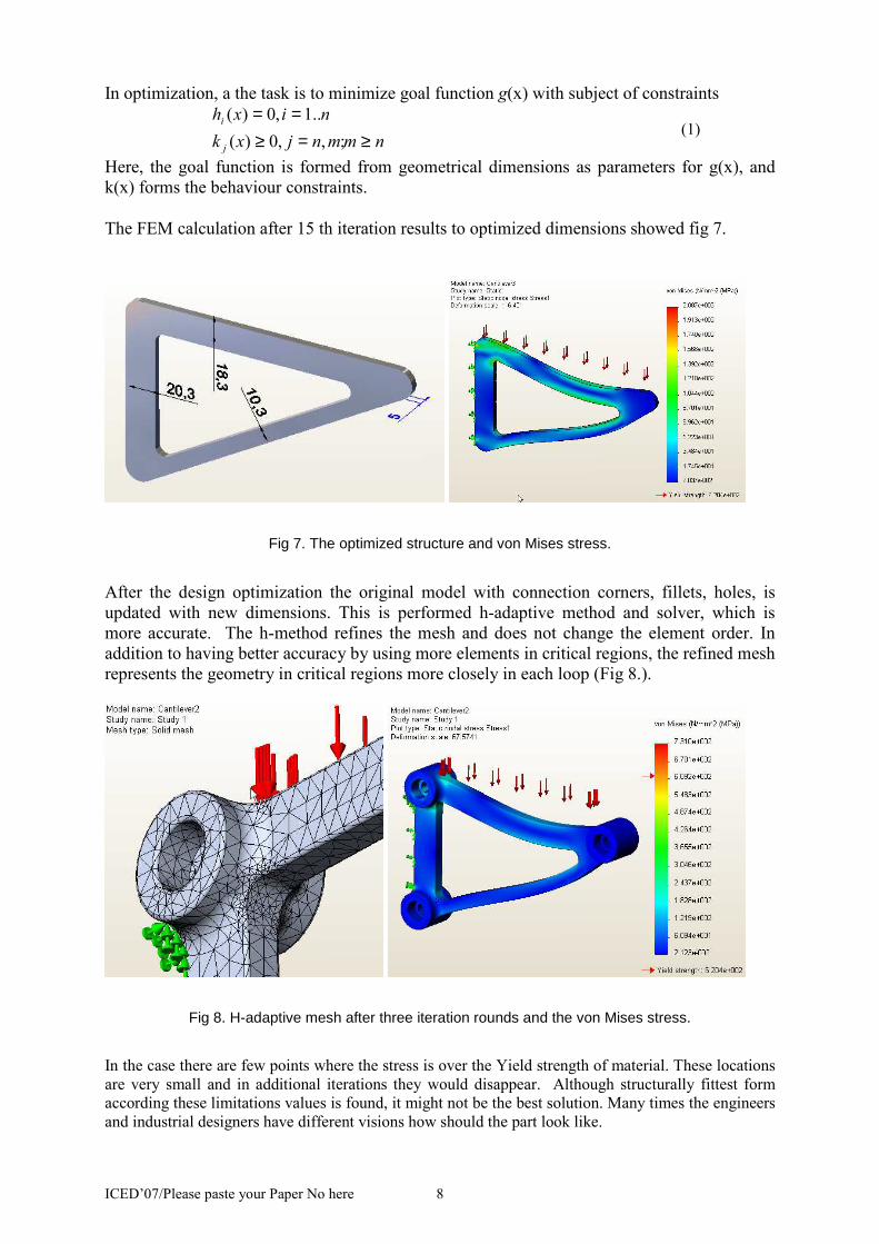
The FEM calculation after 15 th iteration results to optimized dimensions showed fig 7.
Fig 7. The optimized structure and von Mises stress.
After the design optimization the original model with connection corners, fillets, holes, is
updated with new dimensions. This is performed h-adaptive method and solver, which is
more accurate. The h-method refines the mesh and does not change the element order. In
addition to having better accuracy by using more elements in critical regions, the refined mesh
represents the geometry in critical regions more closely in each loop (Fig 8.).
Fig 8. H-adaptive mesh after three iteration rounds and the von Mises stress.
In the case there are few points where the stress is over the Yield strength of material. These locations
are very small and in additional iterations they would disappear. Although structurally fittest form
according these limitations values is found, it might not be the best solution. Many times the engineers
and industrial designers have different visions how should the part look like.
ICED’07/Please paste your Paper No here 9
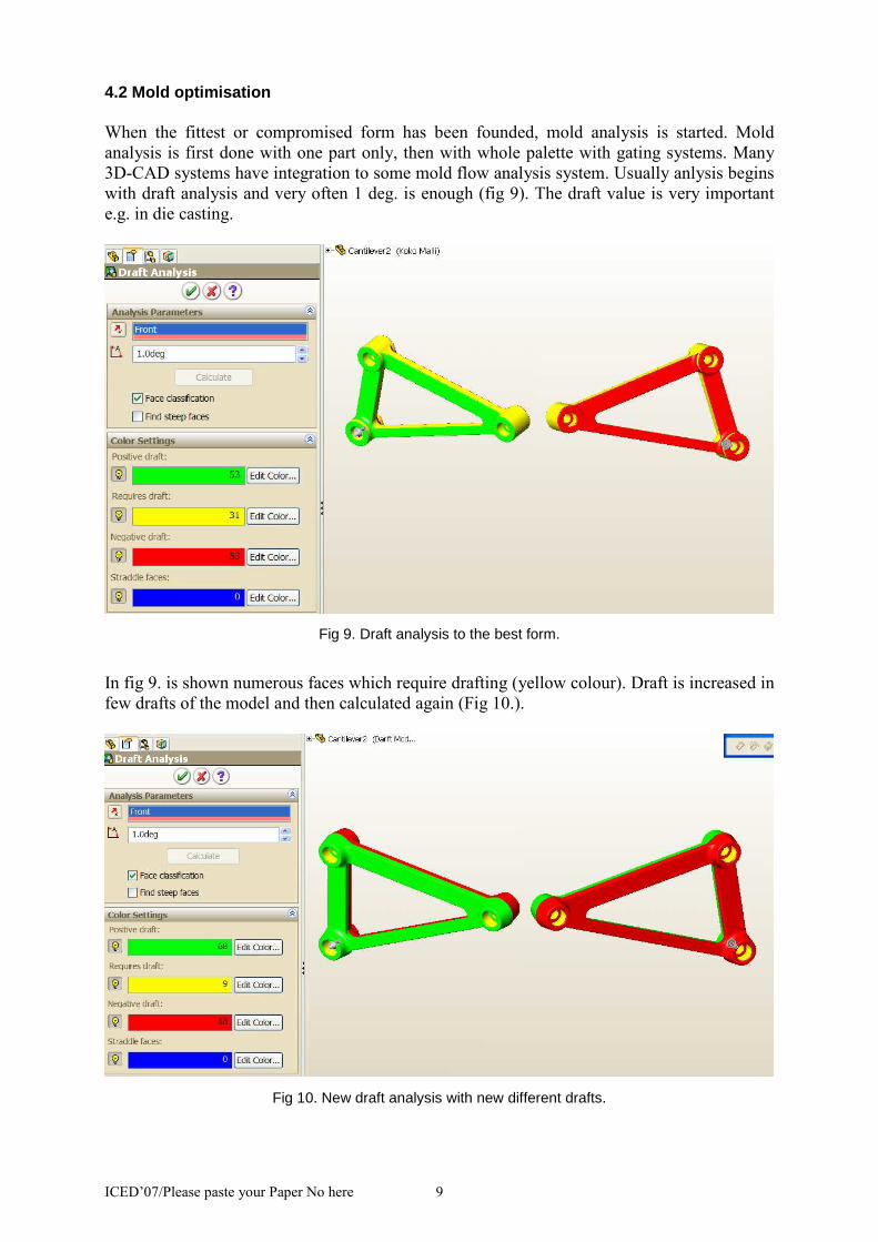
4.2 Mold optimisation
When the fittest or compromised form has been founded, mold analysis is started. Mold
analysis is first done with one part only, then with whole palette with gating systems. Many
3D-CAD systems have integration to some mold flow analysis system. Usually anlysis begins
with draft analysis and very often 1 deg. is enough (fig 9). The draft value is very important
e.g. in die casting.
Fig 9. Draft analysis to the best form.
In fig 9. is shown numerous faces which require drafting (yellow colour). Draft is increased in
few drafts of the model and then calculated again (Fig 10.).
Fig 10. New draft analysis with new different drafts.
ICED’07/Please paste your Paper No here 10
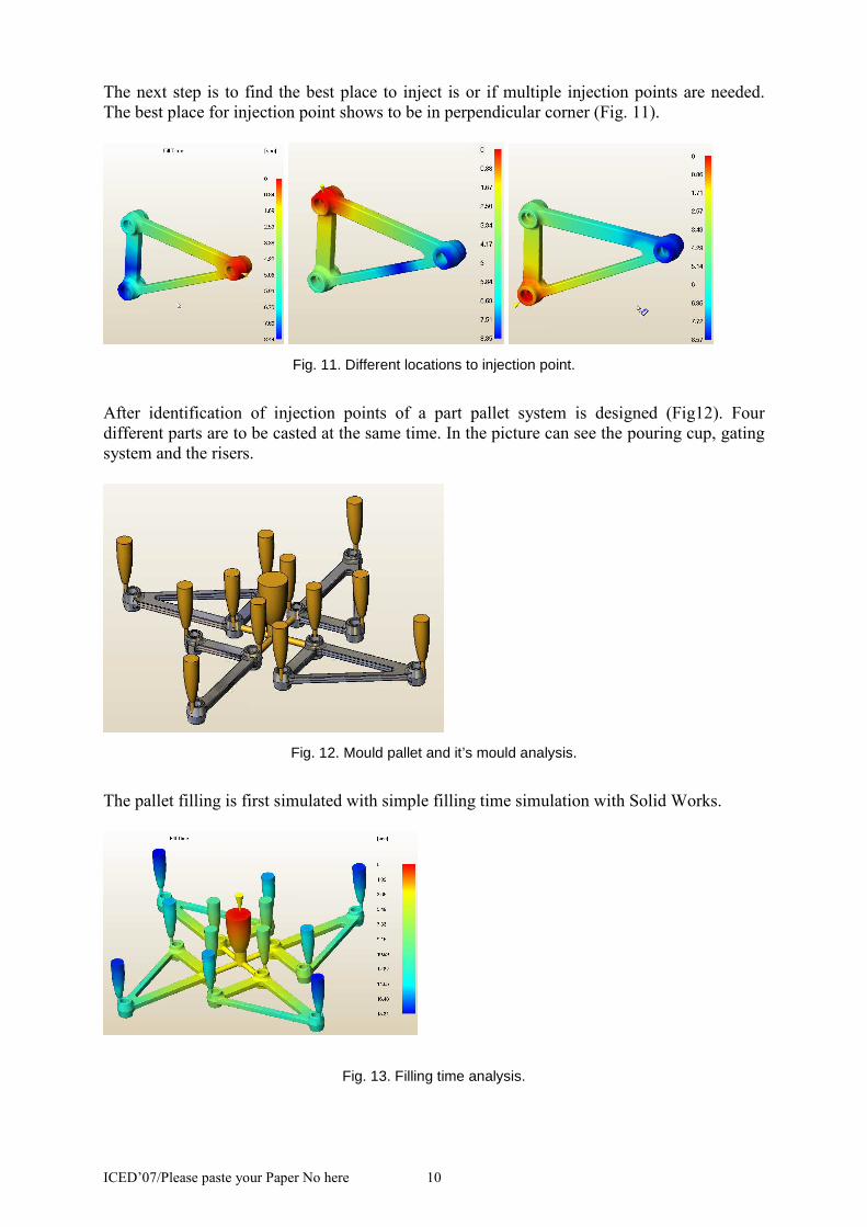
The next step is to find the best place to inject is or if multiple injection points are needed.
The best place for injection point shows to be in perpendicular corner (Fig. 11).
Fig. 11. Different locations to injection point.
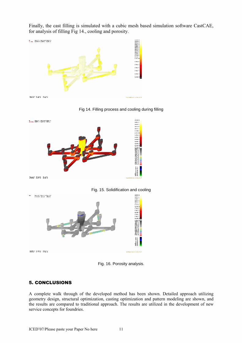
After identification of injection points of a part pallet system is designed (Fig12). Four
different parts are to be casted at the same time. In the picture can see the pouring cup, gating
system and the risers.
Fig. 12. Mould pallet and it’s mould analysis.
The pallet filling is first simulated with simple filling time simulation with Solid Works.
Fig. 13. Filling time analysis.
ICED’07/Please paste your Paper No here 11
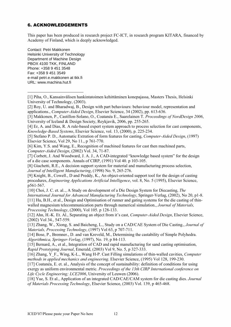
Finally, the cast filling is simulated with a cubic mesh based simulation software CastCAE,
for analysis of filling Fig 14., cooling and porosity.
Fig 14. Filling process and cooling during filling
Fig. 15. Solidification and cooling
Fig. 16. Porosity analysis.
5. CONCLUSIONS
A complete walk through of the developed method has been shown. Detailed approach utilizing
geometry design, structural optimization, casting optimization and pattern modeling are shown, and
the results are compared to traditional approach. The results are utilized in the development of new
service concepts for foundries.
ICED’07/Please paste your Paper No here 12
6. ACKNOWLEDGEMENTS
This paper has been produced in research project FC-ICT, in research program KITARA, financed by
Academy of Finland, which is deeply acknowledged.
Contact: Petri Makkonen Helsinki University of Technology Department of Machine Design PBOX 4100 TKK, FINLAND Phone: +358 9 451 3548 Fax: +358 9 451 3549 e-mail petri.e.makkonen at tkk.fi URL: www.machina.hut.fi
[1] Piha, O., Kansainvälisen hankintatoimen kehittäminen konepajassa, Masters Thesis, Helsinki
University of Technology, (2003).
[2] Roy, U. and Bharadwaj, B., Design with part behaviours: behaviour model, representation and
applications., Computer-Aided Design, Elsevier Science, 34 (2002), pp. 613-636.
[3] Makkonen, P., Castillon-Solano, O., Coatanéa E., Saarelainen T. Proceedings of NordDesign 2006,
University of Iceland & Design Society, Reykjavik, 2006, pp. 255-265.
[4] Er, A. and Dias, R. A rule-based expert system approach to process selection for cast components,
Knowledge-Based Systems, Elsevier Science, vol. 13, (2000), p. 225-234.
[5] Stefano P. D., Automatic Extration of form features for casting, Computer-Aided Design, (1997)
Elsevier Science, Vol 29, No 11., p 761-770.
[6] Kim, Y.S. and Wang, E., Recognition of machined features for cast then machined parts,
Computer-Aided Design, (2002) Vol. 34, 71-87.
[7] Corbett, J. And Woodward, J. A. J., A CAD-integrated “knowledge based system” for the design
of a die case somponents. Annals of CIRP, (1991) Vol 40. p 103-105.
[8] Giachetti, R.E., A decision support system for material and manufacturing process selection,
Journal of Intelligent Manufacturing, (1998) No. 9, 265-276.
[9] Knight, B., Cowell., D and Preddy, K., An object-oriented support tool for the design of casting
procedures, Engineering Applications Artificial Intelligence, vol. 8, No. 5 (1995), Elsevier Science,
p561-567.
[10] Choi, J. C. et. al.., A Study on development of a Die Design System for Diecasting, The
International Journal for Advanced Manufacturing Technology, Springer-Verlag, (2002), No 20, p1-8.
[11] Hu, B.H., et al., Design and Optimisation of runner and gating systems for the die casting of thin-
walled magnesium telecommunication parts through numerical simulation., Journal of Materials,
Processing Technology, (2000), Vol 105. p 128-133.
[12] Ahn, H.-K. Et. Al., Separating an object from it’s cast, Computer-Aided Design, Elsevier Science,
(2002) Vol 34., 547-559.
[13] Zhang, W., Xiong, S. and Baicheng, L., Study on a CAD/CAE System of Die Casting., Journal of
Materials, Processing Technology, (1997) Vol 63, p 707-711.
[14] Bose, P., Bremner., D. and van Kreveld, M., Determining the castability of Simple Polyhedra.
Algorithmica, Springer-Verlag, (1997), No. 19, p 84-113.
[15] Bernard, A., et al., Integration of CAD and rapid manufacturing for sand casting optimisation,
Rapid Prototyping Journal, Emerald, (2003) Vol 9, No. 5, p 327-333.
[16] Zhang, Y_F., Wing, K-L., Wang H-P. Cast Filling simulations of thin-walled cavities, Computer
methods in applied mechanics and engineering. Elsevier Science, (1995) Vol 128, 199-230.
[17] Coatanéa, E. et. al., Analysis of the concept of sustainability: definition of conditions for using
exergy as uniform environmental metric. Proceedings of the 13th CIRP International conference on
Life Cycle Engineering; LCE2006, University of Leuwen (2006).
[18] Yue, S. Et al., Application of an integrated CAD/CAE/CAM system for die casting dies. Journal
of Materials Processing Technology, Elsevier Science, (2003) Vol. 139, p 465-468.