a specification paradigm for the design and implementation of
TRANSCRIPT

A Specification Paradigm for the Design andImplementation of Tangible User Interfaces
ORIT SHAER
Computer Science Department, Wellesley College
and
ROBERT J.K JACOB
Computer Science Department, Tufts University
Tangible interaction shows promise to significantly enhance computer-mediated support for activ-
ities such as learning, problem solving, and design. However, tangible user interfaces are currently
considered challenging to design and build. Designers and developers of these interfaces encounterseveral conceptual, methodological and technical difficulties. Among others, these challenges in-
clude: the lack of appropriate interaction abstractions, the shortcomings of current user interface
software tools to address continuous and parallel interactions, as well as the excessive effort re-quired to integrate novel input and output technologies. To address these challenges, we propose
a specification paradigm for designing and implementing Tangible User Interfaces (TUIs), that
enables TUI developers to specify the structure and behavior of a tangible user interface usinghigh-level constructs, which abstract away implementation details. An important benefit of this
approach, which is based on User Interface Description Language (UIDL) research, is that these
specifications could be automatically or semi-automatically converted into concrete TUI imple-mentations. In addition, such specifications could serve as a common ground for investigating
both design and implementation concerns by TUI developers from different disciplines.Thus, the primary contribution of this paper is a high-level UIDL that provides developers,
from different disciplines means for effectively specifying, discussing, and programming, a broad
range of tangible user interfaces. There are three distinct elements to this contribution: a visualspecification technique that is based on Statecharts and Petri Nets, an XML-compliant language
that extends this visual specification technique, as well as a proof-of-concept prototype of a Tan-
gible User Interface Management System (TUIMS) that semi-automatically translates high-levelspecifications into a program controlling specific target technologies.
Categories and Subject Descriptors: D.2.2 [ Design Tools and Techniques]: User Interfaces;
H5.2. [ User Interfaces]: UIMS
General Terms: Design, Languages
Additional Key Words and Phrases: Tangible Interaction, User Interface Description Language,User Interface Management System, Tangible User Interfaces
1. INTRODUCTION
In the last decade we have seen a wave of Human Computer Interaction (HCI)research aimed at fusing the physical and digital worlds. This work has led to the
...Permission to make digital/hard copy of all or part of this material without fee for personal
or classroom use provided that the copies are not made or distributed for profit or commercial
advantage, the ACM copyright/server notice, the title of the publication, and its date appear, andnotice is given that copying is by permission of the ACM, Inc. To copy otherwise, to republish,to post on servers, or to redistribute to lists requires prior specific permission and/or a fee.c© 2009 ACM 0000-0000/2009/0000-0001 $5.00
ACM Journal Name, Vol. V, No. N, June 2009, Pages 1–39.
2 · O. Shaer and R. Jacob
development of a broad range of systems relying on embedding computation withinthe physical world. Such systems often employ metaphors that give physical formto digital information and are referred to in the literature as Tangible User Inter-faces (TUIs) [Ishii and Ullmer 1997; Hornecker and Buur 2006]. TUIs are designedto take advantage of users‘ well-entrenched knowledge and skills of interaction withthe everyday non-digital world, such as spatial, motor and social skills [Jacob et al.2008]. By leveraging users‘ existing skills, TUIs offer the possibility of natural inter-faces that are intuitive to use and learn. To date, TUI research shows a potential toenhance the way people interact with and leverage digital information in a varietyof application domains including learning, collaborative planning and authoring,and problem solving.
However, although TUIs offer the possibility of interfaces that are easier to learnand use, they are currently more difficult to design and build than traditionalinterfaces. TUI developers face several conceptual, methodological and technicaldifficulties including the lack of appropriate interaction abstractions, the shortcom-ings of current software tools to address continuous and parallel interactions, andthe excessive effort required to integrate novel input and output technologies. Thismay explain why despite their promise, to date, TUIs are still mostly hand builtprototypes, designed and implemented in research labs by graduate students.
In this paper, we propose a new paradigm for developing TUIs that is aimed at al-leviating the challenges inherent to the design and implementation of TUIs. Ratherthan using a particular toolkit for programming a TUI, we propose to specify thestructure and behavior of a TUI using high-level constructs, which abstract awayimplementation details. An important benefit of this approach, which is based onUser Interface Description Language (UIDL) research [Olsen 1992], is that thesespecifications could be automatically or semi automatically converted into concreteTUI implementations. In addition, our experience shows that such specifications area useful common ground for discussing and refining tangible interaction within aninterdisciplinary development team. To support this approach, this paper presentsTUIML (Tangible User Interface Modeling Language), a high-level UIDL aimed atproviding TUI developers from different disciplines means for specifying, discussingand iteratively programming tangible interaction. TUIML consists of a visual spec-ification technique that is based on Statecharts [Harel 1988] and Petri Nets [Petri1962], and an XML-compliant language. We also present a top-level architectureand a proof-of-concept prototype of a TUIMS that semi-authomatically convertsTUIML specifications into concrete interface.
As TUIs evolve from research prototypes into applications for complex domains,carefully studying a TUI prior to its implementation will become crucial for creat-ing functional and usable interfaces. While existing toolkits lower the threshold forimplementing TUIs, TUIML provides a comprehensive set of abstractions for speci-fying, discussing and programming tangible interactions. The design of TUIML is aresult of a user-centered design process in which we leveraged our experience build-ing TUIs as well as our experience teaching a Tangible User Interfaces Laboratorycourse over four years.
This paper is organized as follows: we first summarize findings from our investi-gation of the design process of TUIs. Next, we present TUIML’s visual specifica-ACM Journal Name, Vol. V, No. N, June 2009.

A Specification Paradigm for Tangible User Interfaces · 3
tion techniques as well as its XML-compliant form. We discuss the results of ourevaluation of the language and present a top-level architecture for TUIMS and aprototype. We close with related work.
1.1 Investigating TUIs’ Development Process
To better understand the challenges facing TUI developers, we investigated thedevelopment process of TUIs. In addition to an extensive literature review, ourown experience building TUIs, provided experiential knowledge. We also taught agraduate-level TUI laboratory course that was structured around a team project,the development of a novel functional TUI prototype. Over the five semester inwhich we instructed the course (Tufts University, Spring 05, 06, 07, 08 and Summer07), our students developed 14 new TUIs, some of these TUIs were presented atthe Tangible and Embedded Interaction conference (see Figure 1). The courseemployed heterogeneous implementation technologies including RFID, computervision, and micro-controllers. The students worked in interdisciplinary teams thatincluded students with backgrounds in Computer Science, Engineering, Arts, ChildDevelopment, and Education. From observing our students at work and analyzingtheir design and implementation artifacts we gathered additional insight into thedevelopment process of TUIs. Following, we summarize our findings.
Fig. 1. TVE [Zigelbaum et al. 2007] (left): a TUI for collaborative video editing, implemented with
communicating handheld computers. Marble Track Audio Manipulator [Bean et al. 2008] (center):an augmented toy for collaborative music authoring, implemented with an IPAC controller. Smart
Blocks [Girouard et al. 2007] (right): computational manipulatives for learning basic geometrical
concepts, implemented with RFID.
1.2 TUI Development Challenges
We found that TUI developers face a set of conceptual, methodological and technicaldifficulties throughout the development process of TUIs, as described below. Someof these challenges were preliminary discussed in [Shaer et al. 2004].
1.2.1 Designing an Interplay of Virtual and Physical. As TUIs employ bothvirtual and physical objects an important role of a TUI developer is to inventmetaphors that give physical form to digital information, and to determine whichinformation is best represented digitally and which is best represented physically[Ullmer 2002]. To make physical representations legible, TUI developers are re-quired to consider design issues such as physical syntax [Ullmer 2002], dual feed-back loop (digital and physical), perceived coupling (the extent to which the link
ACM Journal Name, Vol. V, No. N, June 2009.

4 · O. Shaer and R. Jacob
between users actions and systems response is clear) [Hornecker and Buur 2006]and observability (the extent to which the physical state of the system indicateits internal state). However, to date, there are no frameworks or tools that pro-vide vocabulary and means for systematically investigating these issues. Hence, thediscussion, comparison and refinement of designs in respect to these issues oftenperformed in an ad-hoc way that does not support concise communication. In ourTUI laboratory, a general theme among students was that developing their TUIconceptual design was the most challenging. As one student reported “The biggestdifficulties were conceptual. After deciding on the high-level concept, we struggledto refine the interaction techniques“.
1.2.2 Selecting from Multiple Behaviors and Actions. While a widget in a GUIencapsulates its behavior, the behavior of a physical object in a TUI is not deter-mined by its nature alone but also by that objects context of use. The behavior ofa physical interaction object may change when a new physical object is added tothe TUI or when it is physically associated with another physical object. Thus, foreach interaction object, a TUI developer is required to define a behavior for eachpossible context of use. Furthermore, in the physical world there are numerousactions that can be performed with, or upon, any physical object. It is the roleof the TUI developer to select and define which actions are meaningful in whichcontext, communicate this information to users, and implement a solution for com-putationally sensing these actions. However, current tools and interaction modelsdo not provide means for systematically defining a set of alternative behaviors foreach physical interaction object.
1.2.3 The Lack of Standard Input and Output Devices. Currently, there areno standard I/O devices for TUIs. Among the technologies for tracking objects,gestures and users in the physical world are RFID, computer vision, microcontrollersand sensors. A variety of actuators are used for creating physical output. In manycases, a TUI is prototyped several times using different technology in each iteration.As each of these technologies currently requires a different set of physical devicesand instructions, integrating and customizing novel technologies is difficult andcostly. In addition, it is common to implement a particular interaction design bycombining or customizing technologies. In our TUI laboratory teams that combinedtechnologies often reported integration difficulties.
1.2.4 Designing Continuous Interaction. When continuously interacting with aTUI, users perceive that there is a persistent connection between a physical ob-ject and digital information. However, current tools and techniques do not providemeans for exploring continuous interaction. Furthermore, existing event-based soft-ware models fail to capture continuous interaction explicitly. Thus, TUI developersare often required to deal with continuous interaction using low-level programming.
1.2.5 Designing Parallel Interaction. In a TUI, multiple users can interact inparallel with multiple physical objects. In addition, a single action may be per-formed in parallel across multiple physical objects. When designing parallel in-teraction, TUI developers are required to consider issues such as access points[Hornecker and Buur 2006], spatial and temporal coordination. However, existingACM Journal Name, Vol. V, No. N, June 2009.

A Specification Paradigm for Tangible User Interfaces · 5
models usually handle multiple input devices by serializing all input into one com-mon stream [Jacob et al. 1999]. This method is not appropriate for TUIs, since theinput is logically parallel. (We refer here to parallel design at the conceptual andsoftware model level, not at the microprocessor level).
1.2.6 Crossing Disciplinary Boundaries. Designing and building a TUI requirescross-disciplinary knowledge. Thus, TUIs are often developed by interdisciplinaryteams. While each discipline contributes skills necessary for building TUIs, it alsobrings different terminologies and work practices. To date, there are no languagesand tools that provide TUI developers from different disciplines a common groundfor addressing TUI development challenges. In our class, interdisciplinary teamsexperienced communication and workload division problems. As one student ex-plained “The division of labor problem cropped up partially because we were unableto come up with a clear specification“. Another student described “We didnt welldocument how different parts will come together so this created a challenge whenwe put things together, communication is definitely the key“.
1.3 Current Tools Supporting the Development of TUIs
Several tools and techniques are currently used by TUI developers to addressthese challenges. Following we review these tools and techniques and discuss theirstrengths and limitations.
1.3.1 Sketches, Diagrams and Low-Fidelity Prototypes. Sketches and diagramsdominate the early ideation stages of TUI development. TUI developers use sketchesand diagrams for experimenting with high-level concepts such as tangible represen-tations, physical form, and user experience. However, as Blackwell et al. observed,this exploration process is separate from the design of the dynamic behavior and theunderlying software structure [Blackwell et al. 2005]. To date, there is no graphicallanguage that provides TUI developers from different disciplines a common groundfor exploring both form and function. TUI developers also build low-fidelity proto-types to examine the form and function of a TUI, and to communicate alternativedesigns within an interdisciplinary development team. However, low-fidelity proto-types often captured the main use scenario, overlooking alternative scenarios andboundary cases.
1.3.2 Storyboards. Storyboarding is a common technique for demonstrating in-teractive systems behavior [Truong et al. 2006]. However, storyboarding is lesseffective for describing the behavior of TUIs becuse continuous and parallel inter-actions are difficult to depict. Rather, TUI developers often use storyboards todepict concepts such as physical surroundings, user motivation, and emotion.
1.3.3 Functional TUI prototyping using toolkits. Several toolkits have emergedto support the implementation of functional TUI prototypes e.g. [Greenberg andFitchett 2001; Ballagas et al. 2003; Klemmer et al. 2004; Hartmann et al. 2007].The major advantage of such toolkits is that they lower the threshold for imple-menting functional TUI prototypes by handling low-level events. However, as mosttoolkits provide support for specific technology, each time a TUI is prototyped us-ing different technology and hardware, a TUI developer is required to learn newinstructions and rewrite code. Furthermore, although toolkits lower the threshold
ACM Journal Name, Vol. V, No. N, June 2009.
6 · O. Shaer and R. Jacob
for building functional prototypes, they fall short of providing a comprehensive setof abstractions for specifying and discussing tangible interaction.
1.4 A Specification Paradigm for Designing and Implementing TUIs
Considering the limitations of existing tools and techniques in alleviating TUI de-velopment challenges, we propose a specification paradigm for designing and im-plementing TUIs. Rather than implementing a TUI using a toolkit for a particularhardware technology, we propose that TUI developers would specify the structureand behavior of a TUI using a high-level UIDL, which abstracts away implemen-tation details. An important benefit of this approach, which is based on UIDLresearch [Olsen 1992], is that these specifications could be automatically or semiautomatically converted into different concrete implementations. Thus, addressingthe challenge of a lack of standard input and output devices. In addition, such spec-ifications could serve as a common ground for TUI developers from different back-grounds to systematically investigate a variety of design issues. Thus, alleviatingthe conceptual challenges of designing an interplay of virtual and physical, design-ing continuous and parallel interactions, as well as mitigating the methodologicalchallenge of crossing disciplinary boundaries. Our first step toward constructinga comprehensive specification paradigm for TUIs was the TAC framework [Shaeret al. 2004] that introduced a set of high-level constructs for describing the struc-ture of TUIs. In this paper, we extend the TAC framework and present TUIML(Tangible User Interface Modeling Language), a UIDL that is capable of describ-ing both the structure and the behavior of TUIs. While TUIML draws upon theconstructs introduced by the TAC framework for describing the structure of TUIs,it introduces an interaction model and novel specification techniques for capturingthe dynamic behavior of TUIs.
TUIML aims at providing developers from different backgrounds means for spec-ifying, discussing, and iteratively programming TUIs. However, given the complex-ity and the nature of TUI development challenges, we believe that like software ingeneral, there is no silver bullet [Brooks 1987] to make TUI design and implemen-tation easier. Rather, we suggest combining the use of TUIML with the techniquesand tools discussed above to better address TUI development challenges.
2. TANGIBLE USER INTERFACE MODELING LANGUAGE
TUIML is a User Interface Description Language for TUIs. In order to offer a lan-guage that serves as a common ground for TUI developers from different disciplinesin addressing both design and implementation concerns, we implemented TUIMLin two forms: a visual language and an XML-compliant language. Following wedescribe these two implementations of TUIML.
2.1 A Visual Modeling Language
TUIML’s visual form combines iconic and diagrammatic approaches, thus, drawingfrom current practices of both user interface and software design: sketching anddiagrammatic modeling. TUIML consists of three diagramming techniques for de-scribing the structure and behavior of TUIs in a technology independent manner.To clearly explain the TUIML notation, we have selected Urp [Underkoffler andACM Journal Name, Vol. V, No. N, June 2009.

A Specification Paradigm for Tangible User Interfaces · 7
Ishii 1999] as an example because it is one of the most fully developed and knownTUI systems. Urp is a TUI for urban planning that allows users to collaborativelymanipulate physical building models and tools upon a surface, in order to performan analysis of shadows, proximities, and wind. When a building model is added tothe surface, it casts graphical shadow, corresponding to a solar shadow. The dis-tance between two buildings is measured using a physical distance-measuring tool.Finally, a computational fluid flow simulation is bound to a physical wind tool. Byadding this object to the surface, a wind-flow simulation is activated. Changing thephysical orientation of the wind tool alters the orientation of the simulated wind.Though additional features are available, this describes the functionality necessaryto understand our examples. Figure 2 shows the Urp interface.
Fig. 2. Urp [Underkoffler and Ishii 1999], a TUI for urban planning.
2.1.1 Describing the Structure of a TUI Using TUIML. To describe the struc-ture of a TUI, TUIML uses a compact set of constructs that includes tokens, con-straints and TAC elements. These constructs were defined in the TAC paradigm[Shaer et al. 2004]. Following we introduce a visual notation for these constructs.
A Token is a graspable physical object that represents digital information. Aphysical object is considered a token only after it is bound to a variable. Usersinteract with tokens in order to access or manipulate the digital information theyrepresent. The physical properties of a token may reflect the nature of the informa-tion it represents. For example, we consider the building models in Urp as tokensas they represent virtual buildings in a computational model. Users interact withphysical building models in order to create and alter this model. We also considerthe distance-measuring tool and the wind tool as tokens. TUIML depicts tokensusing an iconic notation that convey their shape and orientation but abstracts awayother physical properties that are specified using a secondary textual notation. To-kens are depicted as simple geometrical shapes that contain a variable. The shapesused to represent a token vary: TUIML offers abstract geometrical shapes, how-ever, a TUI developer may choose to use shapes that resemble the actual look ofa certain object. Each shape that is used to represent a token should contain agraphical symbol that represents the variable bound to this token. This additionalrange of expressiveness have no syntactic meaning thus, TUI developers can freelyuse customized shapes. By blending informal with formal notation, TUIML sup-ports users from different backgrounds at different stages of the TUI developmentprocess. Figure 3, shows TUIML representations of widely used tokens. When a
ACM Journal Name, Vol. V, No. N, June 2009.

8 · O. Shaer and R. Jacob
TUI contains several instances of the same token type (e.g. eight building models),rather than drawing each separately, TUIML enables to define a token type andthen mark the number of token instances using multiplicity indicators.
A Constraint is a physical object that limits the behavior of a token with whichit is associated. The physical properties of a constraint guide the user in under-standing how to manipulate a token with respect to that constraint and how tointerpret configurations of tokens and constraints. For example, in Urp we considerthe surface as a constraint because it confines the interaction with building models.It also serves as a reference frame for interpreting the position of building models.Certain physical object may serve as a token, a constraint or both. For example,we consider a building model as a token. However, in the context of measuringdistance between two building models, a building model is considered as a con-straint because it limits the range of the distance measuring interaction. TUIMLdepicts constraints using an iconic notation that conveys their shape, orientationand relative size. Again, other physical properties could be specified using a textualsecondary notation. Figure 3, shows a TUIML library of widely used constrainttypes. For each constraint type we define its visual representation, a list of thephysical relations possible between this constraint and associated tokens and, a listof user manipulations it supports. TUI developers can easily extend the TUIMLnotation by adding new constraint types.
A TAC (Token And Constraints) is a relationship between a token and one ormore constraints. A TAC relationship often expresses to users something aboutthe kinds of interactions an interface supports. TAC relationships are defined bythe TUI developer and are created when a token is physically associated witha constraint. For example, in the Urp system, we consider the configuration ofa building model upon a surface as a TAC. Such a TAC is created or modifiedwhenever a building model is added to the surface. Interacting with a TAC involvesphysically manipulating a token with respect to its constraints. Such interaction hascomputational interpretation. Manipulation of a token outside its constraints hasno computational interpretation. TAC relationships may have a recursive structureso that a given TAC element can serve as a token of another TAC element. Suchrecursive structure can be used to physically express hierarchical grammars. Weview TAC objects as similar to Widgets because they encapsulate the internal stateand behavior of physical objects.
To specify the structure of a TUI using TUIML, a TUI developer first describesthe set of physical objects employed by a TUI. To define a physical object, a TUIdeveloper provides a name, visual representation and a list of properties. Then,the TUI developer creates a TAC palette, a table that contains all possible TACrelationships of a TUI. Thus, defines a grammar of ways in which objects can becombined together to form meaningful expressions. Such expressions can be in-terpreted both by users and computational systems. The listing of possible TACrelationships is done in terms of representation, association and manipulation. Rep-resentation refers to the binding of a physical object to an application variable tocreate a token and to the selection of other physical objects that constrain thistoken. Association refers to the physical association of a token and a set of con-straints. Finally, manipulation refers to the actions a user may perform upon aACM Journal Name, Vol. V, No. N, June 2009.

A Specification Paradigm for Tangible User Interfaces · 9
Fig. 3. Graphical representation of tokens, constraints and TAC elements.
TAC. Figure 4 depicts Urp‘s TAC palette.
The TAC palette allows developers to visually describe the structure of TUIs interms of tokens, constraints, and TAC elements. It provides TUI developers withmeans for examining issues such as form, physical syntax, and context of use, thatare discussed in the challenges of Designing an Interplay of Virtual and Physical,and Multiple Behaviors and Actions. Also, by providing means for declaring theTAC entities that could exist simultaneously, TUIML addresses aspects related toParallel Interaction.
2.1.2 Describing Behavior Using TUIML. Current user interface specificationlanguages mainly rely on event-driven models for specifying and programming thecurrent generation of graphical user interfaces. Event-based models are also usedfor specifying Post-WIMP interfaces and programming discrete 3D and physicalinteractions [Appert and Beaudouin-Lafon 2006; Hartmann et al. 2006; Wingraveand Bowman 2008]. However, they seem as a wrong model for explicitly specifyingcontinuous and parallel behaviors, which are common in TUIs. Thus, TUIML offersa novel interaction model for describing the underlying behavior of TUIs.
To develop an interaction model that describes the dynamic behavior of a TUI,we examined and studied the dialogue structure and the behavior of a large va-riety of TUIs. We also analyzed artifacts such as storyboards, natural languagedescriptions and sketches, all represent common practices for describing TUI be-havior. Through this investigation we recognized two fundamental event types thatrepeat throughout an interaction with a TUI and may cause a mode change in aninterface: 1) dynamic binding of digital information to physical interaction objects(i.e. when users couple information to physical objects of their choice) 2) physical
ACM Journal Name, Vol. V, No. N, June 2009.

10 · O. Shaer and R. Jacob
Fig. 4. Urp‘s [30] TAC palette
association of objects (e.g. when users physically add or connect physical interac-tion objects to each other). Both event types cause a mode change in an interfacebecause they either alter the meaning of an interaction or modify the range of pos-sible interactions. For example, consider the Urp system, when a second buildingis added to the surface, the set of possible interactions is modified users can notonly add, remove and move a building model but also measure the distance be-tween two buildings. Thus, we identified the basic structure of a tangible dialogueas a sequence of modes or high-level states. However, within each high-level state,multiple users may interact with the system, in a discrete or continuous manner,in parallel or consecutively. Hence, we view the underlying behavior of a TUI as acollection of orthogonal user interactions, each represents a thread of functionality(i.e. task) and is nested within a high-level state.
This leads to a two-tier model for describing the behavior of TUIs. Our two-tiermodel contains a dialogue tier and an interaction tier (figure 5). The dialogue tierprovides an overview of the tangible interaction dialogue and consists of a set ofhigh-level states and transitions. The interaction tier provides a detailed view ofeach user interaction (i.e. task) that represents a thread of functionality. Following,we introduce a notation for each tier.
The Dialogue Tier. State transition diagram based notations have proven effec-tive and powerful for specifying graphical user interfaces [Olsen 1984; Jacob 1986;Appert and Beaudouin-Lafon 2006] and would be a natural choice for representingthe dialogue-tier of our model. However, state diagrams tend to emphasize themodes or states of a system and the sequence of transitions from one state to an-other, while for TUIs it is important to emphasize that each state contains a setof tasks that could be executed in parallel. Thus, our representation of a dialoguediagram draws upon the Statechart notation [Harel 1988], a state-based notationACM Journal Name, Vol. V, No. N, June 2009.

A Specification Paradigm for Tangible User Interfaces · 11
Fig. 5. A two-tier model for describing the behavior of TUIs. The dialogue tier (at the top)
describes a set of high-level states a TUI can be in. Each high-level state contains a set of tasks
that can be performed when the system is in this state. A zoom in into the dialogue tier revealsthe interaction tier: a collection of individual task diagrams nested within each state. Each of
these diagrams is represented by a triangle. The internal structure of a task diagram will be
explained later in this section.
that enables one to express concurrency within a state. Similarly to Statecharts,TUIML expresses concurrency within a state, but rather than nested concurrentstate machines, a TUIML state contains concurrent task diagrams. Task diagramsare based on Petri Nets [Petri 1962] and are designed to capture parallel activitiesconstrained by shared resources. The structure of a task diagram is discussed laterin this section.
Rather than describing the state of a TUI at every turn, which would lead toa state explosion, a high-level state captures a context in which certain tasks areavailable. These tasks are orthogonal and could be performed in parallel assumingtheir pre-conditions are satisfied. Formally, a high-level state encapsulates threeelements: an internal state, a physical state and a set of meaningful interactions.It is denoted by a rounded rectangle and each of the tasks it contains is denoted bya triangle separated from others by a dashed line. Similar to a Statechart [Harel1988], a dialogue diagram may have initial, final and error states. A transitionbetween high-level states occurs as a result of an event that changes the context inwhich interactions take place. A transition is associated with an event, a conditionand a response. In a TUI, several actors may generate transition events. Thus,TUIML introduces four transition types:timer, system, user interaction, and trig-ger.
Figure 6, shows the dialogue diagram of the Urp system. The diagram consistsACM Journal Name, Vol. V, No. N, June 2009.

12 · O. Shaer and R. Jacob
of three high-level states: an initial state where no building models are locatedupon the surface, a state where one building model is located upon the surface anda state where at least two building models are located upon the surface. Each ofthese high-level states contains a set of tasks that users can complete (in sequence orin parallel) while the system is within this state. In the Urp system the transitionsfrom one high-level state to another (or back to the same state) are all a resultof user interaction, transitions are associated with a condition (noted as C:) and aresponse (noted as R:).
Fig. 6. Urp‘s dialogue diagram
The Interaction Tier. While the dialogue-tier provides an overview of the tan-gible dialogue structure, the interaction-tier provides a detailed view of each userinteraction that represents a particular task or thread of functionality. A tangibleinteraction typically consists of a set of discrete actions and continuous manipula-tions performed consecutively or in parallel upon physical interaction objects. Forexample, the interaction aimed at distance measuring in the Urp interface con-sists of a sequence of two discrete user actions: connecting two buildings using adistance-tool (results in displaying the distance between the two buildings) anddisconnecting the buildings when the distance display is no longer required. Alter-natively, to drive a car down the road users perform two continuous manipulationsthat are performed in parallel: controlling the steering wheel and adjusting the gaspedal. The interaction-tier depicts this decomposition of tangible interactions intoa set of discrete actions and continuous manipulations and specifies the temporalrelations between them. For each action or manipulation (discrete or continuous)the diagram specifies an actor, pre-conditions, and post-conditions.
TUIML represents the interaction-tier as a collection of task diagrams each nestedwithin a high-level state. It depicts interaction diagrams using a graphical notationthat is inspired from Petri Nets [Petri 1962]) because Petri Nets provides an appeal-ing graphical representation for specifying systems that exhibit parallel activitieswhile being constrained by shared resources. Extensions for Petri nets are used fordescribing the internal behavior of direct manipulation and 3D interfaces [BastideACM Journal Name, Vol. V, No. N, June 2009.

A Specification Paradigm for Tangible User Interfaces · 13
and Palanque 1990; Janssen et al. 1993]. However, Petri nets support neither con-tinuous activity nor explicit description of objects. Hence, while our notation drawsupon the basic structure of Petri nets to express parallelism, it modifies and en-hances the original Petri net notation to produce a graphical notation that explicitlycaptures these characteristics of tangible interaction.
The basic structure of a task diagram comprises three types of nodes: places,actions and manipulations that are connected by directed arcs. Places representconditions in terms of physical or digital configurations, actions represent discreteevents, and manipulations represent continuous interactions. The diagram is di-vided into two areas: a physical and a digital world. Figure 7, shows Urp‘s wind-simulation task diagram. Following we further describe the structure this diagram.
Fig. 7. Urp‘s wind simulation task diagram. Rectangles depict actions, hexagons depict continuousmanipulations.
Places represent pre and post conditions. In a TUI, pre and post conditionsmay relate to both the physical and the digital states of the system. For exampleconsider the action addWindTool in figure 7. In order for this action to activatethe wind simulation the following pre-conditions must be true: the Urp surfaceshould contain at least one building, the Urp system should contain a wind-tool,but it shouldnt be located upon the surface, the digital flag windSimulationOnshould be set to false. TUIML represents places using a mixed notation: physical
ACM Journal Name, Vol. V, No. N, June 2009.
14 · O. Shaer and R. Jacob
conditions are expressed in terms of tokens, constraints and TACs, digital conditionsare represented using text enclosed within an oval node.
Actions are depicted using a box. The actor responsible for generating an actionis specified within the box, if no actor is specified, the default actor is the user. Theinputs of an action are its pre-conditions, the outputs are its post-conditions. Arcsmay be associated with a weight function (i.e. marking) that expresses how manyinstances of a certain physical interaction object are required for an action to beexecuted. The wind-simulation task diagram contains two user generated actions:addWindTool and removeWindTool. During the simulation of a task diagram, itsinitial marking changes according to the sequence of executed actions. Actions thatconclude the sequence of executed actions are connected to a special output placecalled recycler that has no outgoing arcs. Following the execution of such an action,the original marking is recovered.
Manipulations are depicted using a hexagon node. A continuous manipulationlast while its pre-conditions hold and may produce continuous digital output. Whilea manipulation may also produce physical output (e.g. movement), it cannot changethe physical state of the system in terms of tokens and constraints configurations.Rather, a continuous manipulation occurs within a particular configuration of to-kens and constraints. Thus, places that represent physical conditions serve as bothpre and post-conditions of an associated manipulation and are connected to a ma-nipulation node using a thick bi-directional arc.
In the wind-manipulation task diagram, there is one manipulation node, moveWind-Tool. A pre-condition for this manipulation is a physical configuration, which con-tains building models and a wind-tool upon a surface. The movement of the wind-tool upon the surface does not change this physical configuration (it only changesthe position of the wind-tool), thus, a bi-directional arc connects the moveWind-Tool manipulation to the place, which represents this physical configuration. ThemoveWindTool manipulation causes a continuous update of the digital wind simu-lation display.
A manipulation may also fire a transition in response to a certain variable cross-ing a threshold. For example when a user slides an object away from anotherobject, the corresponding manipulation fires an event as a result of the distancebetween the objects crossing a certain threshold. In such cases, the manipulationnode is connected using a regular outgoing flow relation (i.e. an outgoing arc) to atransition that represents the trigger generated event that in turn stops this con-tinuous manipulation. An example for such a manipulation can be found later inthe specification of the Tangible Query Interfaces.
A user can stop a continuous manipulation by changing one of its pre-conditions.For example, figure 8 depicts a TUI that consists of a train physical model thatmoves upon a track. A manipulation tagged moveTrain describes the continuousmovement of the train on the track. A user can stop the moveTrain manipulation,by simply removing the train from the track. The system may stop a continuousmanipulation by either changing its pre-conditions or by generating an event thatdirectly stops the continuous manipulation. For example, in figure 8, the continuousmanipulation moveTrain is generated by the system when a train is placed upona track if the value of the timer in the digital state of the system equals 0. OnceACM Journal Name, Vol. V, No. N, June 2009.

A Specification Paradigm for Tangible User Interfaces · 15
Fig. 8. A Task diagram describing a continous manipulation, move train, that is performed by
the system and can be stopped by either the system or the user.
activated, this manipulation continuously increases the timer. When the timerreaches the value of 120, the system generates an event that stops the train. Notethat the moveTrain manipulation is connected to the stopTrain action using aregular outgoing flow relation.
Finally, some tasks contain manipulations or actions that depend on coordinationbetween actors or between the two hands of a single actor (two-hands interaction).Unlike scenarios where two actors perform independent actions simultaneously, werefer here to cases that require actions or manipulations to be temporally and/orspatially coordinated. For example in a video game, flying an airplane requiresa user (i.e. pilot) to adjust a speed lever while handling the stick (two-hands in-teraction), while another user (i.e. navigator) may shoot the enemy. By allowingmanipulation and action nodes to serve as pre and post conditions of other ac-tion or manipulation nodes, TUIML enables the specification of temporally and/orspatially coordinated actions and manipulations.
2.1.3 Summary. TUIML is aimed at specifying, analyzing and refining tangibleinteraction. To accomplish these goals it provides means for visualizing the struc-ture and behavior of TUIs. TUIML defines three types of diagrams: The first, theTAC palette, represents the structure of a TUI, the other two diagrams types, thedialogue diagram and the task diagram represent its dynamic behavior.
Visually specifying the structure of a TUI in terms of tokens, constraints, andTAC elements, provides TUI developers with means for examining issues such asform, physical syntax and context of use. The two-tier model, and the dialogue andtask diagrams presented here are intended to enable TUI developers to describeand discuss a TUI‘s behavior from a point of view closer to the user rather thanto the exigencies of implementation. The dialogue diagram aims to bring out thebig picture, and assist TUI developers to assure that functionality is complete
ACM Journal Name, Vol. V, No. N, June 2009.
16 · O. Shaer and R. Jacob
and correct prior to implementation. The task diagram allows TUI developers tofocus on a specific thread of functionality and provides means for addressing designconcerns related to parallel interaction, dual digital and physical feedback loops, andcombined discrete and continuous inputs. The comparison of task diagrams allowsTUI developers to consider alternative designs. We intend that applying TUIMLwith a high level of formality could also yield a detailed specification document thatcan serve to guide implementation. Following we describe an XML-compliant formof TUIML, that formalizes TUIML specifications.
2.2 TUI Markup Language
In addition to the visual form of TUIML, we defined an XML-compliant form forTUIML. This XML-compliant form is intended as an intermediate language fora Tangible User Interface Management System (TUIMS) that compiles TUIMLspecifications to code, and for interoperating with other user interface softwaretools. It also serves as a secondary notation for the visual form of TUIML, allowingusers to specify properties of tokens and constraints as well as to specify which tokenand TAC relationships are created at design time and which at run-time. Whilethe XML-compliant form of TUIML was not intended directly for user input, it isreasonably human readable and is supported by existing parsing and editing tools.We used the grammar-based XML schema mechanism to formalize the structureand content of TUIML documents.
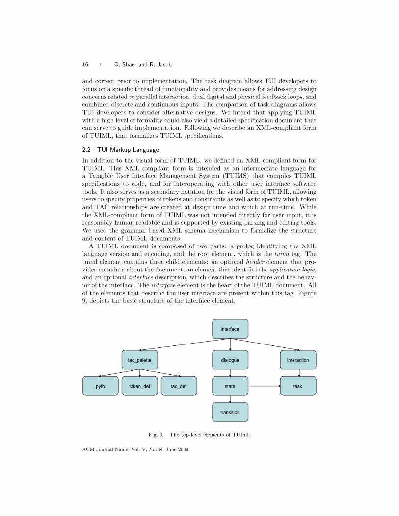
A TUIML document is composed of two parts: a prolog identifying the XMLlanguage version and encoding, and the root element, which is the tuiml tag. Thetuiml element contains three child elements: an optional header element that pro-vides metadata about the document, an element that identifies the application logic,and an optional interface description, which describes the structure and the behav-ior of the interface. The interface element is the heart of the TUIML document. Allof the elements that describe the user interface are present within this tag. Figure9, depicts the basic structure of the interface element.
Fig. 9. The top-level elements of TUIml.
ACM Journal Name, Vol. V, No. N, June 2009.

A Specification Paradigm for Tangible User Interfaces · 17
The tac palette element describes the structure of a TUI in terms of physicalinteraction objects, tokens, and TAC relations. This element begins with an enu-meration of physical interaction objects (i.e. pyfos) that are not bound to digitalinformation. The tac palette element then lists tokens using token def element. Aninteresting aspect of TUIs is that tokens can be either statically bound to digitalinformation by the designer of the system, or dynamically bound by the user atrun-time. When a token is statically bound, its token def element contains a uniquename and an application variable. When a token is dynamically bound its token defelement contains a unique class name and a variable type. In addition a token defelement may contain property elements that describe the physical properties ofthe token. Similiarly to a token a TAC entity could be statically or dynamicallycreated. The corresponding tac def element of a statically created TAC is given aunique name. The corresponding tac def element of a dynamically created TAC isgiven a unique class name.
The dialogue element consists of a sequence of state elements. Each state is givena unique id and contains the following elements: internal state,physical state, a col-lection of task elements, and a collection of transition elements. The internal stateelement describes the value of relevant application variables. The physical state el-ement describes the physical configuration of the system in terms of token and TACrelations. Task elements represent the interaction tasks a user can perform whilethe system is within this particular state. Finally, a transition element may containa condition element that must be true in order for the transition to fire, a responseelement and a tuiml event element that maps the high-level transition event to aTUIML event that could later be mapped into a low-level event. TUIML eventsinclude tokenAdded, tokenRemoved, tokenUpdated and tokenPropertyChanged.
The interaction element consists of a sequence of task elements. Each task elementrepresents a task diagram of a different user interaction or thread of functionality.In defining the structure of a task element we drew upon the Petri Net MarkupLanguage [Weber and Kindler 2003]. A task element consists of the followingelements: physical place, digital place, recycler, action, manipulation and arc. Eachof these elements could be omitted or repeated as needed.
2.3 TUIML Modeling Tools
We developed three prototypes of a visual modeling environment for TUIML. Theseprototypes served as working models for investigating the transformation of visualTUIML specifications to XML-compliant form, as well as for eliciting requirementsfor a complete modeling environment for TUIML. The first prototype shielded usersfrom the underlying TUIML syntax by allowing users to sketch 3D interactionobjects and bind them to behavior using forms. The second prototype, provideda visual editor for TUIML diagrams, it allowed users to create, modify, and savediagrams using a set of pre-defined shapes and tools, users could also load newshapes to be used in their diagrams. Our most recent prototype extended this visualeditor and implemented it an Eclipse plug-in. It enabled to visually manipulateTUIML objects and easily connect them to application logic. Our findings fromdeveloping and informally evaluating these prototypes played an important role inrefining the design of TUIML.
ACM Journal Name, Vol. V, No. N, June 2009.
18 · O. Shaer and R. Jacob
2.4 Scope and Limitations
TUIML, was mostly designed to specify data-centerd TUIs [Hornecker and Buur2006], a design perspective that is primarily pursued within HCI and ComputerScience and results in systems that use spatially configurable physical artifacts asrepresentations and controls for digital information [Ullmer 2002]. Examples ofdata-centered TUIs that are directly addressed by TUIML include Interactive Sur-faces, Constructive Assemblies and Token+Constraints [Ullmer 2002]. TUIML canalso be used to specify certain aspects of other TUI design perspective such as thespace-centered [Hornecker and Buur 2006] view that focuses on the design of in-teractive spaces and the expressive-movement-centered view [Hornecker and Buur2006], that emphasizes expressive movement. However, currently TUIML does notprovide means for specifying unique characteristics of these design perspectivessuch as expressive gestures. Also, several research areas are closely related to TUIs.These include Tangible Augmented Reality, Tangible Table-Top Interaction, andAmbient Displays. TUIML provides means for describing the structure and be-havior of such interfaces by enabling the specification of body parts as tokens orconstraints, of discrete and continuous touch-based interactions, and of implicitinteraction. Finally, several emerging interaction styles, including touch-based in-teraction, ubiquitous computing, embodied Interaction [?] ,and mixed reality, sharesalient commonalities with TUIs [Jacob et al. 2008]. Thus, TUIML can describecertain aspects of these interaction styles, but it does not provide means for com-prehensively specifying these interaction styles. Finally, TUIML is not intended asa generative design tools, rather it aims at specifying, discussing and iterativelyprogramming tangible interaction.
3. EVALUATION
Our evaluation of TUIML focuses on three desirable properties: High ceiling [Myerset al. 2000], the ability to describe a broad range of TUIs. Low threshold [Myerset al. 2000], the extent to which the language is easy to learn and use. Utilityand applicability, the ability to alleviate development challenges, and to be ap-plied without excessive effort. We employed two evaluation methods in concert:specification of benchmark TUIs, and analysis of use by students.
3.1 Specifying Benchmark TUIs using TUIML
Using benchmarks is a known evaluation process in some areas of Human-ComputerInteraction (HCI) such as information visualization [Plaisant 2004]. In this section,we report on a benchmark that we have created for the purpose of evaluating theTUIML notation. The benchmark consists of a set of TUIs that are considered thestate-of-the-art in the field of tangible interaction. We have chosen to include in thebenchmark TUIs that serve as representatives of a larger class of TUIs, so togetherthey cover an important and large subset of the TUI design space. In our selectionof TUI classes we utilized Ullmers division of the TUI design space into three highlevel classifications [Ullmer 2002] and selected representatives from each classifica-tion: Interactive Surfaces, Constructive Assemblies, and Token + Constraint. Wealso selected mainly interfaces that were fully developed, and evaluated. Table 1,lists the nine interfaces that we selected as benchmarks. Each of these interfacesACM Journal Name, Vol. V, No. N, June 2009.

A Specification Paradigm for Tangible User Interfaces · 19
was specified several times throughout the iterative development of TUIML. In ad-dition to the specifications made by the authors, two graduate students specifiedeach of these interfaces. Following, we discuss the TUIML specifications of threebenchmark interfaces. By specifying benchmark interfaces we evaluated not onlythe languages ability to describe a broad range of interfaces in a precise, consistentand simple way, but also the usefulness of the specifications to TUI developers. Welooked at what can be learned from these specifications and whether they highlightaspects of tangible interaction such as the use of physical syntax, mapping betweenshape and function, parallel and continuous interaction.
Table I. Benchmark TUIsInterface TUI category
Urp [Underkoffler and Ishii 1999] Interactive Surfaces
Designers’ Outpost [Klemmer et al. 2001] Interactive Surfaces
Senseboard [Jacob et al. 2002] Interactive Surfaces
TVE [Zigelbaum et al. 2007] Constructive Assemblies
Navigational Blocks [Camarata et al. 2002] Constructive Assemblies
Tern [Horn and Jacob 2007] Constructive Assemblies
Marble Answering Machine [Crampton-Smith 1995] Tokens+Constraints
Tangible Query Interfaces [Ullmer 2002] Tokens+Constraints
Media Blocks [Ullmer 2002] Tokens+Constraints
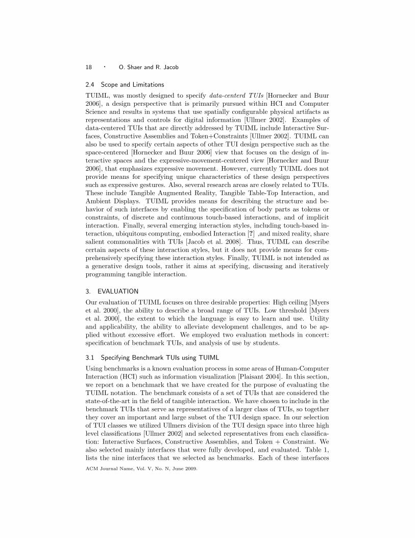
3.1.1 The Marble Answering Machine. One of the earliest illustrations of in-terlinking the physical and digital worlds is provided in the design of the MarbleAnswering Machine (MAM) [Crampton-Smith 1995]. It was designed and proto-typed by Durrell Bishop, while a student at the Royal College of Art, in order toexplore ways in which computing can be taken off the desk and integrated intoevery day objects. Although it was never fully implemented, it is a well-known, in-fluential TUI design that inspired numerous TUI researchers and developers. TheMAM system is a simple and elegant example of a token+constraint TUI [Ullmer2002]. In the Marble Answering Machine, marbles represent incoming voice mes-sages. To play a message, a user grabs a message (marble) and places it in anindentation on the machine. To return a call, the user places the marble withinan indentation in an augmented telephone. To store a message, the user places amarble in a dedicated storage saucer different users may have different saucers.Figure 11, illustrates a design sketch of the Marble Answering Machine.
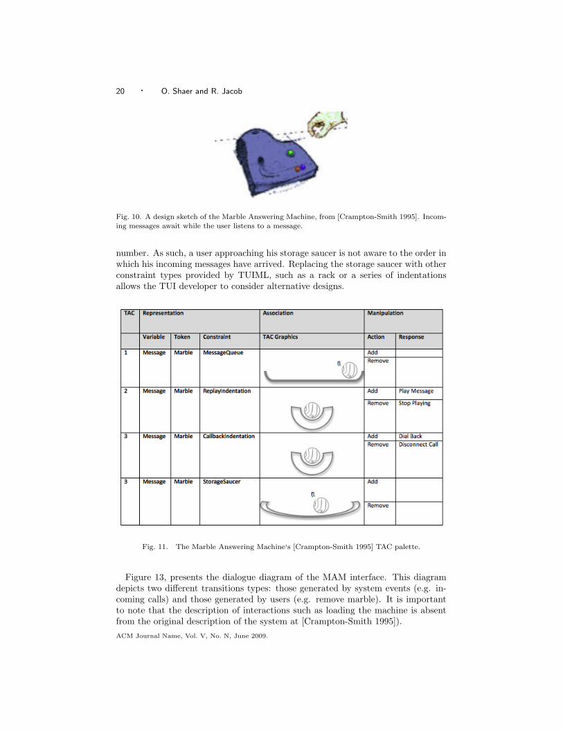
Figure 12, presents the TAC palette for the MAM. Visually specifying the MAMstructure highlights the use of physical constraints to enforce physical syntax. Forexample, TAC 2, consists of a marble and a replay indentation. The shape of thereplay indentation affords the placement of a single marble within its dimensions.The visual specification of a TAC could also assist in comparing alternative designs.For example, within the scope of the MAM, we can compare the structure of TAC1, a marble within a message queue, with the structure of TAC 4, a marble withina storage saucer. While the physical properties of a rack (used for representingthe message queue) imply the following relations: presence, order, and number,the physical properties of a storage saucer only imply the relations of presence and
ACM Journal Name, Vol. V, No. N, June 2009.
20 · O. Shaer and R. Jacob
Fig. 10. A design sketch of the Marble Answering Machine, from [Crampton-Smith 1995]. Incom-
ing messages await while the user listens to a message.
number. As such, a user approaching his storage saucer is not aware to the order inwhich his incoming messages have arrived. Replacing the storage saucer with otherconstraint types provided by TUIML, such as a rack or a series of indentationsallows the TUI developer to consider alternative designs.
Fig. 11. The Marble Answering Machine‘s [Crampton-Smith 1995] TAC palette.
Figure 13, presents the dialogue diagram of the MAM interface. This diagramdepicts two different transitions types: those generated by system events (e.g. in-coming calls) and those generated by users (e.g. remove marble). It is importantto note that the description of interactions such as loading the machine is absentfrom the original description of the system at [Crampton-Smith 1995]).ACM Journal Name, Vol. V, No. N, June 2009.
A Specification Paradigm for Tangible User Interfaces · 21
Fig. 12. The Marble Answering Machine‘s [Crampton-Smith 1995] dialogue diagram.
Comparing the play and call back interaction diagrams (Figure 14), highlights aconsistent interaction syntax across these two interactions. Also, from consideringthe interaction objects required for completing each of those interactions (a mar-ble and a play indentation for playing, a message and a marble and a call backindentation for calling back) we learn that these two interactions could take placein parallel assuming the MAM contains at least two different messages.
3.1.2 Navigational Blocks. Navigational Blocks [Camarata et al. 2002] (see fig-ure 15) is a TUI for information space exploration. It consists of four blocks, eachrepresents a major category of historical data. Each face of these blocks is boundto a different instance of this category. To explore the historical information, usersinteract with these blocks within an active space. Placing a block within the ac-tive space displays information from the block category, for example, locating thewho block within the active space displays a list of historical figures. Rotating ablock within the active space, queries the applications database and displays theinformation related to the topic represented by the upper face of the block. Trans-lating a block (i.e. sliding), within the active space, scrolls through the displayedinformation. In addition, users may explore the relationships between two informa-tion categories by attaching two blocks together to express a boolean AND. If twotopics (those represented by the upper faces of the blocks) are related the blocksattract each other, if these topics are not related the two blocks repel each other.Locating the attached blocks within the active space displays the results of an ANDquery. The Navigational Blocks system can be viewed as a constructive assemblyTUI [Ullmer 2002] because it allows users to create computational expressions byattaching blocks.
Figure 16, depicts the TAC palette of the Navigational Blocks system. It is inter-ACM Journal Name, Vol. V, No. N, June 2009.

22 · O. Shaer and R. Jacob
Fig. 13. The Marble Answering Machine‘s [Crampton-Smith 1995] Call (left) and Play (right)
task diagrams.
Fig. 14. Navigational Blocks [Camarata et al. 2002]
esting to note, that while the MAM interface [Crampton-Smith 1995] uses physicalconstraints with one degree of freedom (1DOF) to enforce digital syntax, the Nav-igational Blocks system constrains the tangible interaction to the dimensions ofan active space (6DOF). By choosing so, the Navigational Blocks system providesusers with less guidance regarding which possible interactions are meaningful butfurther encourages users to explore the system. Thus, users may try interactingwith the system in several ways, some of them meaningful and defined by the systemdesigner (e.g. adding a block to the active space) while others (e.g. adding severalun-attached blocks to the active space) may result in an error. The TAC paletteACM Journal Name, Vol. V, No. N, June 2009.

A Specification Paradigm for Tangible User Interfaces · 23
provides TUI developers with a systematic way for defining those manipulationsthat are meaningful, and identifying manipulations that are probable but are notmeaningful.
Fig. 15. Navigational Blocks’ [Camarata et al. 2002] TAC palette.
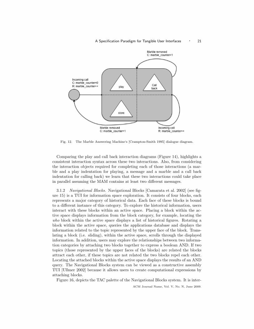
Figure 17, depicts the Navigational Blocks dialogue diagram. It contains fourhigh-level states: an initial states in which no blocks are present within the interac-tive space, a state in which one block is present within the interactive space, a statewhere two attached blocks are present within the interactive space, and an errorstate. Constructing this diagram highlights some use cases that are not specifiedin (Camarata et al., 2002) (e.g. the presence of two or more un-attached blockswithin the active space).
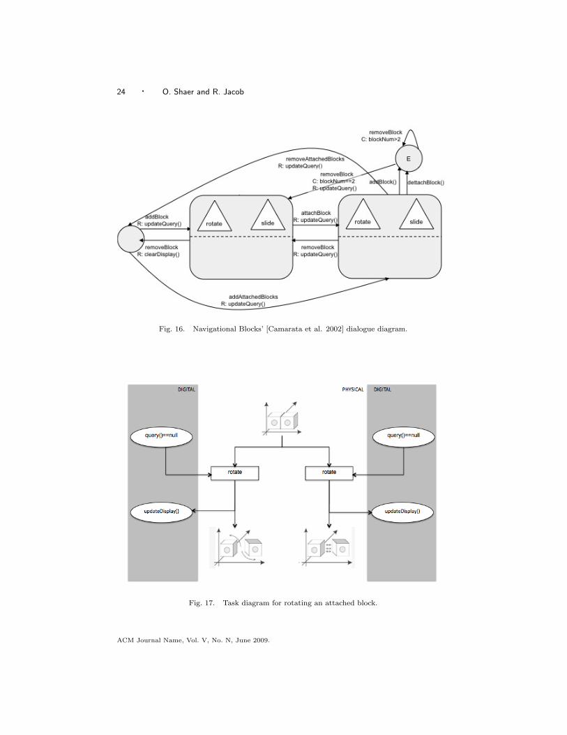
Figure 18, depicts the task diagram describing the rotation of a block that ispart of two attached blocks (i.e. an AND query). It is interesting to note thatthe Navigational Blocks system could respond in one of two ways to the rotationof a block that is already attached to another if the two topics represented bythe blocks top faces produce non empty query results the blocks attract each otherotherwise they repel each other. Therefore, the rotate action in figure 18 has twopossible physical outputs, This is an example of active tokens that provide physicalfeedback attraction or repulsion. Currently, due to technical challenges only a fewsystems employ active tokens, however, in the future we anticipate that TUIs willoften provide physical feedback to physical input.
ACM Journal Name, Vol. V, No. N, June 2009.
24 · O. Shaer and R. Jacob
Fig. 16. Navigational Blocks’ [Camarata et al. 2002] dialogue diagram.
Fig. 17. Task diagram for rotating an attached block.
ACM Journal Name, Vol. V, No. N, June 2009.

A Specification Paradigm for Tangible User Interfaces · 25
3.1.3 Tangible Query Interfaces. Tangible Query Interfaces [Ullmer 2002] is arepresentative of the Token + Constraint category. It uses physically constrainedtokens to express, manipulate and visualize parameterized database queries. Severalprototypes of the Tangible Query Interfaces were built; each uses different physicaltoken and constraints to represent query parameters. Here we refer to a prototypethat employs parameter bars for representing query parameters (figure 19). Eachparameter bar is equipped with a display and two sliders. By adjusting the slidersof a certain parameter bar, users can determine the upper and lower boundariesof the parameter this bar represents. When a bar is attached to the query rack,the query results are displayed. If more than one parameter bar is attached to thequery rack, the system applies an AND operator to adjacent parameter and an ORoperator to distant ones.
Fig. 18. Tangible Query Interfaces [Ullmer et al. 2005]
Figure 20, shows the TAC palette of a Tangible Query Interfaces prototype thatuses parameter bars. The TAC palette specification highlights the recursive physicalsyntax this interface employs: a closer look at TAC 3 reveals that it consists of atoken, a parameter bar with upper and lower sliders, constrained by a query rack.This token itself is comprised of two TACs, TAC1 and TAC2. By allowing TUIdevelopers to easily describe nested physical structures the TAC palette providesmeans to examine and experiment with physical expressions of recursive grammars.
The dialogue diagram of this tangible query interface (figure 21) shows the sys-tems two high-level states. In the first, one or more parameter bars are active (i.e.bound to a query parameter) but are not associated with the query rack. In thesecond high-level state, at least one parameter bar is physically associated with thequery rack.
When one or more parameter bars are associated with the query rack (i.e. thesystem is in its second high-level state), users could slide a bar along the rack inorder to alter the query. When the manipulated bar becomes adjacent to anotherbar, the system applies the AND operator to the two adjacent parameter bars.When it becomes distant from another parameter bar the system applies the ORoperator to these bars. Figure 21, shows the task diagram for sliding a bar. Note,that the continuous manipulation slide bar generates a discrete event proximity tobar changed. Then, the system produces a digital output and updates the querydisplay. Analyzing the task of sliding a bar using the TUIML notation highlights an
ACM Journal Name, Vol. V, No. N, June 2009.

26 · O. Shaer and R. Jacob
Fig. 19. Tangible Query Interfaces‘ [Ullmer et al. 2005] TAC palette
Fig. 20. Tangible Query Interfaces‘ [Ullmer et al. 2005] dialogue diagram
asymmetry between user interaction (continuous) and system response (discrete).Using TUIML, TUI developers could easily model and experiment with alternativedesigns where the system provides continuous feedback or where the continuousmanipulation of sliding a bar is replaced with a discrete action of, for example,connecting two bars.
3.1.4 discussion. The specification of benchmark TUIs demonstrates that theTUIML notation is capable of describing a broad range of interfaces. We showedthat TUIML is capable of describing TUIs from the Interactive Surfaces, Construc-tive Assemblies and Token+Constraints categories [Ullmer 2002], that togethercover a large and important subset of the tangible interaction design space. TheTUIML description of each of the benchmark interfaces specified is compact andACM Journal Name, Vol. V, No. N, June 2009.

A Specification Paradigm for Tangible User Interfaces · 27
Fig. 21. Task diagram for sliding a bar within the query rack.
readable. In addition, we showed that TUIML provides TUI developers with a sys-tematic way for considering the mapping of form and function, the use of physicalsyntax and the selection of meaningful interactions. Furthermore, we illustratedthat TUIML can be used to compare alternative designs and to reason about par-allel and continuous interactions.
3.2 Evaluating TUIML in the Classroom
Over four semesters, Spring 2006, Spring 2007, Summer 2007, and Spring 2008,we integrated TUIML into our TUI Laboratory course. Students used TUIML foranalyzing an existing TUI, as well as in the design process of a new TUI. As mostTUIs are currently developed by graduate students in research laboratories, thestructure of this course and its interdisciplinary student composition provided uswith an opportunity to study the use of TUIML in conditions similar to those inwhich many existing TUIs were developed. Following, we summarize our findings.
3.2.1 Analyzing Existing TUIs. Over these four semesters, we required studentsto read a TUI research paper, present it to the class and then specify it usingTUIML. In addition to TUIML specifications students were required to submita written discussion of certain aspects of the specified TUI including the use ofphysical syntax, parallel interaction, and treatment of boundary cases. Studentsselected their research paper from a list that changed over the four semesters toinclude recently published TUIs. Overall, the list included the nine benchmarkinterfaces as well as additional eight TUIs.
Overall, 28 students submitted TUIML specifications and a TUI analysis. Inall semesters, we introduced TUIML in a one-hour lecture and provided an onlinetutorial. We did not provide an editing environment for TUIML, so students coulduse pencil and paper, or any computational drawing tool of their choice to createTUIML specifications. Following the submission of their specification and analysis,we asked students to fill in a questionnaire inquiring about their experience usingTUIML. We found that the average time spent on TUIML specifications is 2 hours.The longest time spent on TUIML specifications was 3.5 hours. From examiningstudents‘ secifications, we found that they were consistent with our specificationsand captured similar TAC relationships, high-level states and actions. We alsoasked students how difficult was it to apply TUIML to their TUI of choice (on a scale
ACM Journal Name, Vol. V, No. N, June 2009.

28 · O. Shaer and R. Jacob
of 1 to 5, where 5 is very difficult) and how confident they are that they correctlyidentified TUIML elements (on a scale of 1 to 5, where 5 is very confident). Table2 summarizes students responses to those questions regarding the specification ofour benchmark interfaces. The instances column in table 2 refers to by how manystudents an interface was specified. It is important to note that while this datado not lend itself to statistical analysis and hence cannot be generalized, it showsthat students from a variety of backgrounds understood the concepts of TUIMLand successfully completed the TUIML specification of an existing TUI with onlyminimal training and without exceptional difficulties.
Finally, we asked students what they liked and disliked about TUIML, and inwhat ways TUIML could be improved. Following are selected students’ responses:What students liked: “It (TUIML) forced me to really understand all aspects of theTUI in detail“ (Spring 2006). “The graphical rather than textual description, madeit easier to visually conceptualize the system in different states“ (Spring 2007). “Ithelped me think about aspects of the TUI design that I didnt consider before suchas having multiple users interacting with the system in parallel“ (Spring 2007).“Ilike that it distills complicated systems into much simpler elements that can beused as a framework for comparison“ (Spring 2008) What students disliked: “Iwas a little confused sometimes in the dialogue diagram about what should beconsidered an action and what is a transition“ (Spring 2006). “ It does not supportspecifying changing users, since different users change how data is interpreted Ifeel it is important“(Summer 2007). “With passive user interfaces, TUIs without acontinuous link to an underlying technology, a lot of the meaningful activity that isnot computationally interpreted is lost in the description“ (Spring 2007). Students’suggestions for improvements: “ expanding the pictorial notation will make TUIMLeasier to use and read“, “I would change the symbols used for tokens, they are a bitambiguous“ (Spring 2007, Senseboard). “attributes of tokens are hard to represent,how do you specify a range of values¿‘ (Spring 2006). “introduce error states in thedialogue diagram (Spring 2008).
Table II. Responses to selected questions from the TUIML questionnaire regarding the specification
of benchmark interfaces.
Interface Instances Difficulty Confidence
Urp [Underkoffler and Ishii 1999] Used as an example
Designers’ Outpost [Klemmer et al. 2001] 3 2 3.7
Senseboard [Jacob et al. 2002] 3 2 4
TVE [Zigelbaum et al. 2007] 3 2 4
Navigational Blocks [Camarata et al. 2002] 2 3 4
Tern [Horn and Jacob 2007] 2 2 4.3
Marble Answering Machine [Crampton-Smith 1995] Used as an example
Tangible Query Interfaces [Ullmer 2002] 2 2 3.5
Media Blocks [Ullmer 2002] 2 3.5 3.2
ACM Journal Name, Vol. V, No. N, June 2009.

A Specification Paradigm for Tangible User Interfaces · 29
3.2.2 Using TUIML in the Design Process of TUIs. Between Spring 2006 andSpring 2008, 11 groups of students used TUIML in the design process of their TUIlaboratory course project. We asked students to submit their TUIML specificationswhen their conceptual design was complete and then again with the final documen-tation of their project. Following the completion of their project, we asked studentsto answer a questionnaire about their experience using TUIML. All student groupscompleted and submitted their TUIML specifications without further help from us.The average time that took the groups to complete the first round of specifica-tions was 1.5 hours (as reported by students). The longest time for completion wasreported as 3 hours.
We also asked students about how the TUIML modeling process benefitted theirdesign process. Following are samples of students’ responses: “TUIML helpedus focus more clearly on how our system would work. By abstracting away theimplementation aspect of what we were doing, we were able to design a system thathad fundamentally sound interaction concepts without being distracted by how weare going to actually implement them“, “Once we had the TUIML model it wasmuch easier to divide the work and progress“, “TUIML gave us a clear abstractionof how we wanted the users to interact with the system. This allowed us to focuson designing those pieces well for our prototype, rather than spending a lot of timeon parts that weren’t as crucial to the actual user interaction“, “TUIML made melook at the relationships between our tokens in a new way because I started toconsider how the user would interact with the system and see what implicitly fitstogether“.
3.3 Discussion
The results we presented here have some limitations. First, the evaluation of TU-IML was conducted within a classroom setting, students were required to learnTUIML in order to complete their assignments; thus, we may anticipate some biasin students‘ responses to the questionnaire. Second, students‘ experience with TU-IML may vary between the semesters due to changes in the language itself and inthe online tutorial. Therefore, these evaluation results may only be qualified astentative. However, these results do demonstrate that TUIML is capable of de-scribing a broad range of existing and new TUIs, across the space of the tangibleinteraction design space. Furthermore, our evaluation shows that TUIML has arelatively low threshold. Students from a variety of backgrounds successfully com-pleted the TUIML specifications of an existing TUI with only minimal training.The use of TUIML specifications in the design process of new TUIs, shows thatstudents understood the concepts and possibilities of TUIML and put them to gooduse. Also, the effort required from students to complete TUIML specifications wasnot greater then the effort required to read a scientific paper, create a storyboard,or write a natural language interface description. The specification of benchmarkinterfaces as well as students’ feedback provide some evidence for the utility ofTUIML: exploring and defining relationships between physical interaction objects,considering parallel interaction, comparing alternative designs, highlighting bound-ary cases, and using specifications as a basis for communication. Finally, most ofthe students suggestions for improvement were implemented in the current versionof TUIML.
ACM Journal Name, Vol. V, No. N, June 2009.

30 · O. Shaer and R. Jacob
Having demonstrated that TUIML is capable of describing a broad range of inter-faces,has a low-threshold, and provides utility, next we show that TUIML specifi-cations could be semi-automatically converted into concrete TUI implementationby a TUIMS.
4. TOWARD A TANGIBLE USER INTERFACE MANAGEMENT SYSTEM
A Tangible User Interface Management System (TUIMS), draws upon User Inter-face Management System (UIMS) research to provide support for editing TUIMLspecifications, translating them into concrete implementations, and managing theinteraction with a variety of interaction devices at run-time. Similarly to a UIMS, aTUIMS supports the concept of “dialog independences“ [Hartson and Hix 1989], theseparation of all user interface related code from the application code. This allowschanges to be made in the TUI design without affecting the application code. Thus,it supports iterative prototyping and exploration of new technologies. Following,we lay the foundation for the development of a TUIMS. We present a top-levelarchitecture for a TUIMS, and describe a proof-of-concept TUIMS prototype.
4.1 TUIMS Architecture
In a seminal paper, Foley and Wallace suggested to decompose the user interfacedesign into semantic, syntactic and lexical levels [Foley and Wallace 1974]. Thistop down approach allows useful modularity during the design of user interfacesand serves as a foundation for various user interface software tools including forthe software architecture of many UIMSs [Olsen 1992]. This decomposition is alsofound in our design of the TUIMS architecture (see figure 23) that draws fromUIMS architecture models such as the early Seeheim model [Olsen 1992], and thelater Arch/Slinky [uim 1992] and PAC-Amodeus [Nigay and Coutaz 1991] models.
The TUIMS captures the semantic level of a TUI in the application code. Thesyntactic level of a TUI consists of a description of the logical physical interactionobjects and the manipulation actions users may perform upon them. For eachmanipulation action it provides the context in which it may be performed whichin turn determines which functions to invoke. The syntactic level is captured inthe TUIML models and is translated into the TUIMS model component. Modelingtools can support the development of the TUIML models.
The lexical level of a TUI deals with device discovery and communication aswell as with the precise mechanism by which a user specifies the syntax. A LexicalHandler is a TUIMS component that is responsible for the communication anduser interaction with a set of devices mediated by a particular implementationtechnology. A TUIMS may contain several Lexical Handlers. Physical and graphicaltoolkits can be used in the implementation of a lexical handler. The mapping oflow-level input events to syntactic events is performed by the Lexical Manager.
The Dialog Manager is driven automatically or semi-automatically from TUIMLspecifications. It controls the logical interaction objects and is responsible for in-voking application functions in response to manipulation actions as well as for firingphysical output events in responses to changes in the internal state of the applica-tion. The communication between the Dialog Manager and the Application logicis performed via the semantic interface. The communication between the DialogManager and the Lexical Manager is performed via the syntactic interface while theACM Journal Name, Vol. V, No. N, June 2009.

A Specification Paradigm for Tangible User Interfaces · 31
communication between the Lexical Manger and the lexical handlers is performedvia lexical interfaces.This architecture is intended to facilitate the development oftechnologically portable TUI systems by allowing TUIMS users to modify and addLexical Handlers that support a variety of implementation technologies.
Fig. 22. The TUIMS architecture.
4.2 Proof-of-Concept Prototype
In order to investigate and demonstrate the feasibility of implementing a TUIMS, wedeveloped a proof-of-concept TUIMS prototype. Our prototype is not a completeimplementation of a TUIMS, rather it serves as a working model of a TUIMSback-end that implements the TUIMS top-level architecture. It receives XML-compliant TUIML specifications as input, semi-automatically translates them intoa concrete TUI implementation, and serves as a run-time environment that managesthe communication and interaction with different implementation technologies. Weused this prototype to successfully program several existing TUIs including theMarble Answering Machine [Crampton-Smith 1995], a reduced functionality Urp[Underkoffler and Ishii 1999], and the Marble Track Audio Manipulator [Bean et al.2008]. We chose Java as an implementation language for our prototype because ofits extensive library support, platform independence, the potential to integrateTUIML with emerging TUI toolkits (e.g. [Hartmann et al. 2006; Hartmann et al.2007; Klemmer et al. 2004]), and novice software developers fluency. However,platform independence comes at a performance cost. For the development of mostTUIs we estimated that ease of technology integration and rich library supportgains are more valuable than performance. Following we describe this prototype.
4.2.1 Input Abstraction and Event Generation. The input layer of a TUIMSconsists of a set of lexical handlers that are responsible for the communicationand user interaction with a set of devices mediated by a particular implementation
ACM Journal Name, Vol. V, No. N, June 2009.

32 · O. Shaer and R. Jacob
technology. We developed three lexical handlers supporting implementation tech-nologies that are often used in the development of TUIs: RFID, microcontrollers(Handy Board microcontroller) and arcade controllers (I-PAC Arcade Controller).Following, we briefly describe each of these lexical handlers.
RFIDHandler. This lexical handler communicates with an FEIG OBID i-scanRFID Reader. It polls the RFID reader through a serial connection at regular in-tervals and generates events when tags are added or removed from the readers fieldof view. It generates tagAdded and tagRemoved events, both contain two strings:tag ID and reader ID. The RFIDHandler can also read/write data to individualtags. It is implemented using the Java Communications API.
HBDHandler. The Handy Board microcontroller was designed for experimentalrobotics projects, but it also serves a large number of embedded control applica-tions. The Handy Board is programmed with Interactive C, a subset of the Cprogramming language. The HBDHandler consists of two parts. The first is a Javaprogram that communicates with the Handy Board over a serial connection. It firesan event when new input is read through the serial connection and generates threetypes of events: CircuitOn and CircuitOff which, represent a change in a digitalsensor and contain port ID, and AnalogueChanged which, represents a change inthe value read by an analogue sensor and contains a port ID and a value. TheHBDHandler also enables to send a command to one of the Handy Board motorports. The second part of this lexical handler is an Interactive C program that runson the Handy Board and communicates with its serial connection.
IPACHandler. The I-PAC Arcade Controller is a USB keyboard emulator thatsimplifies input acquisition from switches, arcade buttons, joysticks, etc. A WIN32firmware programmer enables to map input ports to standard keyboard keys. TheIPACThread implements the Java KeyListener interface to receive input from theI-PAC controller. It fires CircuitOn and CircuitOff events that contain port ID.
Fig. 23. TUI implementation technologies supported by our proof-of-concept TUIMS prototype.
Each of these lexical handlers implements the LexicalHandler interface. Unlikea GUI toolkit that typically supports one mouse and one keyboard, several lex-ical handlers can run in parallel supporting multiple input devices and multipleimplementation technologies. Figure 25, shows a class diagram of the TUIMSACM Journal Name, Vol. V, No. N, June 2009.

A Specification Paradigm for Tangible User Interfaces · 33
event handling mechanism. Once a lexical handler fires an event it is dispatchedby a subclass of a TUIMLEventProducer, which is the class responsible for map-ping low-level events to TUIML events. TUIML events include TokenAdded, To-kenRemoved, TokenPropertyChanged and TokenUpdated. While these events areconsistent across the different implementation technologies, each implementationtechnology may provide different information. For each lexical handler there is acorresponding producer class that dispatches low-level events and generates TU-IML events. The separation of input acquisition from event dispatch and genera-tion allows users to modify a particular TUIMLEventProducer instance. A com-plete TUIMS should provide users with an easy way to map low-level events toTUIML events for example by using a form-based interface to edit a particularTUIMLEventProducer. The LexicalManager is responsible for instantiating TU-IMLEventProducer instances and handling exceptions that result from hardwareconfiguration. Finally, the DialogueManager implements the TUIMLEventListenerinterface and dispatches TUIML events. It responds to events by instantiating To-ken and TAC objects as well as by calling application logic methods and updatingthe application state.
Fig. 24. A class diagram of the TUIMS event handling mechanism
ACM Journal Name, Vol. V, No. N, June 2009.

34 · O. Shaer and R. Jacob
4.2.2 Control Flow. The basic flow of control in an application programmedwith TUIMS is that the DialogueManager instantiates the LexicalManager and lis-tens to TUIML events while keeping track of instantiated TUIML objects (i.e.pyfo, token and TAC objects) and of the current application state. It also containsa Factory object that is responsible for instantiating Pyfo, Token and TAC objects.When a TUIML event is dispatched the DialogueManager fires a transition accord-ing to the event type and the current state of an application. The Factory classis used for creating certain Token or TAC objects as a response to a particulartransition. When the system enters a new state the DialogueManager launches athread for each of the tasks available for users to perform when the system is inthat particular state. Each of these threads implements a TUIMLEventListenerinterface and responds to TUIML events according to the pre and post conditionsspecified in the TUIml interaction element. The task threads and the DialogMan-ager both track the physical state of the system. When a task is no longer availablethe DialogManager stops its thread.
4.2.3 Code Generation. Finally, we implemented a TUIml2JavaCompiler thatgenerates Java code from XML-compliant TUIML specifications. Our TUIml2JavaCompilerworks as following:
(1) Creates a class for each specified tac and token elements. A class for a tacelement extends the base class TAC, a class for a token element extends thebase class Token.
(2) Creates a Factory class with create and destroy methods for each TAC or Tokeninstances.
(3) Creates an instance of a Task class for each specified task element.
(4) Instantiates a LexicalManager that contains a reference to a LexicalHandlerand TUIMLEventProducer for each implementation technology discovered bythe TUIml2JavaCompiler.
(5) Creates a DialogueManager class that contains:—reference to a lexical manager.—reference to an application logic.—flag for each task element that is specified in the TUIML interaction element.—reference to a Task instance created for each task element specified.—private init method that instantiates each of the specified pyfo and token
elements.—private initTasks method that initialized each Task instance.—private setTasksFlags method that sets the task flags according to the current
application state.—private fireTransition method that fires each of the specified transitions.
While the compiler generates a skeleton of a concrete Java implementation asdescribed above, currently, a programmer is still required to manually programmethods. Nevertheless, our implementation of the TUIml2JavaCompiler demon-strates that semi-automatic code generation from TUIml specification is feasible.ACM Journal Name, Vol. V, No. N, June 2009.

A Specification Paradigm for Tangible User Interfaces · 35
4.3 Summary
We introduced the concept of a TUIMS, that draws upon UIMS research [Olsen1992] to provide support for editing high-level specifications, translating them intoconcrete implementations, and managing the interaction with a variety of interac-tion devices at run-time. We presented a top-level architecture for a TUIMS anddescribed a proof-of-concept TUIMS prototype that demonstrates input abstractionand event generation, control flow, and semi-automatic code generation. We believethat other aspects of TUIMS implementation such as a visual editing environment,additional lexical handlers, and an integrated development environment could beimplemented by additional programming effort using well-known techniques.
5. RELATED WORK
5.1 User Interface Management System
In the early 1980s, the concept of a user interface management system (UIMS)was an important focus area for the then-forming user interface software researchcommunity [Myers et al. 2000]. The goals of UIMS research were to: simplify thedevelopment of user interfaces by shielding developers from implementation de-tails, to promote consistency across applications, and to facilitate the separationof user interface code from application logic. A UIMS implemented the syntacticand lexical levels of the user interface and conducted the interaction with the user[Olsen 1992]. It allowed designers to specify interactive behavior using a UIDL.This specification was then automatically translated into an executable program orinterpreted at run time. The choice of UIDL model and methods was a key ingre-dient in the design and implementation of the UIMS [Olsen 1992]. Many systemsused techniques borrowed from formal languages or compilers for dialogue specifi-cation, for example: state transition diagrams and advanced state machine models[Newman 1968; Jacob 1986; Olsen 1984], and parsers for context-free grammars(e.g. [Olsen and Dempsey 1983]). Others used event-based specification to specifythe interface responses to IO events (e.g.[Goodman 1987]).
Although UIMS offered a promising approach for simplifying the development ofUIs, this approach has not worked out well in practice [Myers et al. 2000]. WhileUIMS tried to isolate the decision of how the interaction will look and feel from thedesigners and offer a consistent look and feel across applications, designers felt thatthe control of this low level pragmatics is important. Furthermore, most UIDLshad a high-threshold, they required a substantial learning effort to successfullyspecify an interface. Finally, the standardization of UIs on the desktop paradigmmade the need for abstractions from the input/output devices mostly unnecessary.Subsequently, in the last decade, some of the challenges facing the developers onnext generation user interfaces are similar to those that faced GUI developers inthe early 1980. Thus, as part of the user interface software research communityeffort to address these difficulties, the concept of a UIDL reemerged as a promisingapproach.
5.2 Emerging User Interface Description Languages
Several UIDLs, most of them XML-based, have been developed in recent years inorder to accomplish the following goals [Luyten et al. 2004]: capturing the require-
ACM Journal Name, Vol. V, No. N, June 2009.
36 · O. Shaer and R. Jacob
ments for a user interface as an abstract definition that remains stable across avariety of platforms, enabling the creation of a single user interface design for mul-tiple devices and platforms, improving the reusability of a user interface, supportingevolution and extensibility of a user interface, and enabling automated generation ofuser interface code. TUIML shares most of the above goals with emerging UIDLs,while aiming at developing TUIs rather than muti-platform interfaces. SeveralUIDLs that support the generation of multi-platform and multi-modal user inter-faces from a single abstract description, inspired the design of TUIML: The ART-Studio [Calvary et al. 2001], is a tool that supports the design process of plasticuser interfaces by exposing several models to the designer: task, concepts, platform,interactors, abstract and concrete user interfaces. The User Interface Markup Lan-guage (UIML) [Ali et al. 2004], is an XML-based UIDL that provides a deviceindependent method for user interface design. UIML specifications first define theabstract types of user interface components and the code to execute when eventsoccur, and are then further refined into a specific user interface. The USer InterfaceeXtensible Markup Language (USIXML) [Limbourg et al. 2004] allows the speci-fication of task, domain, presentation, and context-of-use models while providinga substantial support for describing relationships between these models. USIXMLsupports the generation of multi-modal user interfaces. Finally,Teresa XML [Pa-terno and Santoro 2002] enables the specification of task models, composition ofinteractors and a user interface dialogue. An extensive set of tools supports thedevelopment of concrete user interfaces from Teresa XML specifications.
While we have witnessed an extensive development of UIDLs for the developmentof user interfaces for multiple platforms and contexts, only few UIDLs address thedevelopment of next generation user interfaces. Jacob et al. presented a softwaremodel, a language and a development environment - PMIW, for describing andprogramming non-WIMP virtual environments [Jacob et al. 1999]. Their modeladdresses the continuous aspect of non-WIMP interaction explicitly by combininga data-flow component for describing continuous relationships with an event-basedcomponent for specifying discrete interactions. The model also supports parallelinteraction implicitly because it is simply a declarative specification of a set of re-lationships that are in principle maintained simultaneously. The model abstractsaway many of the details of specific interaction devices and treats them only interms of the discrete events they produce and the continuous values they provide.Similarly to the PMIW approach, TUIML abstracts implementation details anddescribes the behavior of a TUI using two communicating components. However,TUIML also provides means for explicitly specifying parallel interaction, and fordescribing relations between physical interaction objects. InTML [fig ] and Chasm[Wingrave and Bowman 2008] are more recent UIDLs for describing VR applica-tions. Similarly to PMIW, they are platform and toolkit independent and targetsnon-programmers.
5.3 Toolkits for Physical Interaction
In the last years, the research community has developed several tools to supportphysical computing including Phidgets [Greenberg and Fitchett 2001], iStuff [Bal-lagas et al. 2003], Exemplar [Hartmann et al. 2007] and Papier-Mache [Klemmeret al. 2004]. The major advantage of these toolkits is that they lower the thresholdACM Journal Name, Vol. V, No. N, June 2009.

A Specification Paradigm for Tangible User Interfaces · 37
for implementing fully functional TUI prototypes by hiding and handling low-leveldetails and events. However, they fall short of providing a comprehensive set ofabstractions for specifying and discussing tangible interaction. In section 1.3.3 wediscuss toolkits for physical interaction in further detail.
6. CONCLUSIONS AND FUTURE WORK
This paper contributes TUIML, a high-level UIDL, that supports the design andimplementation of TUIs by providing TUI developers from different backgroundsmeans for specifying, discussing, and programming tangible interaction. There arethree distinct elements to this contribution: a visual specification technique that isbased on Statecharts and Petri Nets, an XML-compliant language that extends thisvisual specification technique, as well as a proof-of-concept prototype of a TUIMSthat semi-automatically translates TUIML specifications and manages the com-munication and interaction with a variety of interaction devices at run-time. Theevaluation of TUIML shows that it is capable of describing a broad range of existingand new TUIs and has a relatively low-threshold. It also demonstrates that TUIMLspecifications alleviate TUI development challenges while requiring an effort thatis not greater than required by existing tools and techniques. Finally, the TUIMSproof-of-concept prototype presented here demonstrate that TUIML specificationscould also be semi-automatically converted to a concrete implementation.
Currently, we are extending TUIML to support whole-body interaction by spec-ifying expressive movement. We also seek to integrate TUIML with standard spec-ification languages and with existing toolkits for tangible interaction.
ACKNOWLEDGMENTS
We thank Judith Stafford, Samuel Gayer, Harriet Fell, Ray Jackendoff, MichaelHorn, Audrey Girouard, Erin Solovey, and Jamie Zigelbaum for their valuablefeedback on this work. We also thank Tufts’ students who provided invaluablesupport for this work: Amy Van Holten, Katelyn Mann and Jeff Livingston. Finally,we thank our students at the TUI laboratory course for sharing their enthusiasm,creativity and insights. This material is based in part upon work supported by theNational Science Foundation under Grant Numbers EHR-0227879 and IIS-0414389.
REFERENCES
1992. A metamodel for the runtime architecture of an interactive system: the uims tool developers
workshop. SIGCHI Bull. 24, 1, 32–37.
Ali, M. F., Perez-Quinones, M. A., and Abrams, M. 2004. Building multi-platform user
interfaces with uiml. In Multiple User Interfaces, S. A. and J. H., Eds. John Wiley and Sons,Chichester, UK, 95–116.
Appert, C. and Beaudouin-Lafon, M. 2006. Swingstates: Adding state machines to the swingtoolkit. In UIST’06: Symposium on User Interface Software and Technology. ACM Press,
Montreux, Switzerland.
Ballagas, R., Ringel, M., Stone, M., and Borchers, J. 2003. istuff: A physical user interfacetoolkit for ubiquitous computing environments. In CHI’03: Human Factors in Computing
Systems. ACM Press.
Bastide, R. and Palanque, P. A. 1990. Petri net objects for the design, validation and proto-
typing of user-driven interfaces. In INTERACT ’90. North-Holland Publishing Co.
ACM Journal Name, Vol. V, No. N, June 2009.
38 · O. Shaer and R. Jacob
Bean, A., Siddiqi, S., Chowdhury, A., Whited, B., Shaer, O., and Jacob, R. J. K. 2008.
Marble track audio manipulator (mtam): a tangible user interface for audio composition. InTEI ’08. ACM.
Blackwell, A., Edge, D., Dubuc, L., Rode, J., Stringer, M., and Toye, E. 2005. Using solid
diagrams for tangible interface prototyping. IEEE Pervasive Computing Oct-Dec, 18–21.
Brooks, F. P. 1987. No silver bullet essence and accidents of software engineering. Com-
puter 20, 4, 10–19.
Calvary, G., Coutaz, J., and Thevenin, D. 2001. A unifying reference framework for thedevelopment of plastic user interfaces. In EHCI ’01: Proceedings of the 8th IFIP International
Conference on Engineering for Human-Computer Interaction. Springer-Verlag.
Camarata, K., Do, E. Y.-L., Johnson, B. R., and Gross, M. D. 2002. Navigational blocks:navigating information space with tangible media. In IUI ’02. ACM.
Crampton-Smith, G. 1995. The hand that rocks the cradle. I.D May/June, 60–65.
Foley, J. D. and Wallace, V. L. 1974. The art of natural graphic man-machine conversation.Proceedings of the IEEE 62, 4, 462–471.
Goodman, D. 1987. The Complete HyperCard Handbook. Bantam Books, New York.
Greenberg, S. and Fitchett, C. 2001. Phidgets: easy development of physical interfaces throughphysical widgets. In UIST ’01. ACM, 209–218.
Harel, D. 1988. On visual formalisms. Comm. ACM 31, 5, 514–530.
Hartmann, B., Abdulla, L., Mittal, M., and Klemmer, S. R. 2007. Authoring sensor-basedinteractions by demonstration with direct manipulation and pattern recognition. In CHI ’07.
ACM.
Hartmann, B., Klemmer, S. R., Bernstein, M., Abdulla, L., Burr, B., Robinson-Mosher,A., and Gee, J. 2006. Reflective physical prototyping through integrated design, test, and
analysis. In UIST ’06. ACM.
Hartson, H. R. and Hix, D. 1989. Human-computer interface development: Concepts andsystems for its management. Computing Surveys 21, 1, 5–92.
Horn, M. S. and Jacob, R. J. K. 2007. Tangible programming in the classroom with tern. In
CHI ’07: extended abstracts on Human factors in computing systems. ACM.
Hornecker, E. and Buur, J. 2006. Getting a grip on tangible interaction: A framework on
physical space and social interaction. In CHI’06: Human Factors in Computing Systems.
ACM, Montreal, Canada, 437–446.
Ishii, H. and Ullmer, B. 1997. Tangible bits: towards seamless interfaces between people, bits
and atoms. In CHI ’97. ACM, 234–241.
Jacob, R. J., Girouard, A., Hirshfield, L. M., Horn, M. S., Shaer, O., Solovey, E. T., andZigelbaum, J. 2008. Reality-based interaction: a framework for post-wimp interfaces. In CHI’08: Proceeding of the twenty-sixth annual SIGCHI conference on Human factors in computing
systems. ACM, New York, NY, USA, 201–210.
Jacob, R. J. K. 1986. A specification language for direct manipulation user interfaces. ACM
Transactions on Graphics 5, 4, 283–317.
Jacob, R. J. K., Deligiannidis, L., and Morrison, S. 1999. A software model and specifica-tion language for non-wimp user interfaces. ACM Transactions on Computer-Human Interac-
tion 6, 1, 1–46.
Jacob, R. J. K., Ishii, H., Pangaro, G., and Patten, J. 2002. A tangible interface for organizinginformation using a grid. In CHI ’02: Proceedings of the SIGCHI conference on Human factors
in computing systems. ACM, New York, NY, USA, 339–346.
Janssen, C., Weisbecker, A., and Ziegler, J. 1993. Generating user interfaces from datamodels and dialogue net specifications. In CHI ’93: Proceedings of the INTERACT ’93 and
CHI ’93 conference on Human factors in computing systems. ACM, 418–423.
Klemmer, S. R., Li, J., Lin, J., and Landay, J. A. 2004. Papier-mache: toolkit support for tan-gible input. In CHI ’04: Proceedings of the SIGCHI conference on Human factors in computing
systems. ACM, New York, NY, USA, 399–406.
ACM Journal Name, Vol. V, No. N, June 2009.
A Specification Paradigm for Tangible User Interfaces · 39
Klemmer, S. R., Newman, M. W., Farrell, R., Bilezikjian, M., and Landay, J. A. 2001. The
designers’ outpost: a tangible interface for collaborative web site. In UIST ’01: Proceedings ofthe 14th annual ACM symposium on User interface software and technology. ACM, New York,
NY, USA, 1–10.
Limbourg, Q., V, J., Michotte, B., Bouillon, L., and Lpez-jaquero, V. 2004. Usixml: a
language supporting multi-path development of user interfaces. Springer-Verlag, 11–13.
Luyten, K., Abrams, M., Vanderdonckt, J., and Limbourg, Q. 2004. Developing user inter-
faces with xml: Advances on user interface description languages. an AVI’04 workshop.
Myers, B., Hudson, S. E., and Pausch, R. 2000. Past, present, and future of user interface
software tools. ACM Transactions on Computer-Human Interaction 7, 1, 3–28.
Newman, W. M. 1968. A system for interactive graphical programming. In AFIPS ’68 (Spring):Proceedings of the April 30–May 2, 1968, spring joint computer conference. ACM, New York,
NY, USA, 47–54.
Nigay, L. and Coutaz, J. 1991. Building user interfaces: organizing software agents. In Esprit’91 Conference Proceedings, ACM, Ed.
Olsen, D. R. 1984. Push-down automata for user interface management. ACM Transactions on
Graphics 3, 3, 177–203.
Olsen, D. R. 1992. User Interface Management Systems: Models and Algorithms. MorganKaufmann, San Francisco. ISBN 1-55860-220-8.
Olsen, D. R. and Dempsey, E. P. 1983. Syngraph: A graphical user interface generator. Com-
puter Graphics 17, 3, 42–50.
Paterno, F. and Santoro, C. 2002. One model, many interfaces. In CADUI. 143–154.
Petri, C. 1962. Communikation mit automaten. Ph.D. thesis, University of Bonn.
Plaisant, C. 2004. The challenge of information visualization evaluation. In AVI ’04: Proceedingsof the working conference on Advanced visual interfaces. ACM, New York, NY, USA, 109–116.
Shaer, O., Leland, N., Calvillo-Gamez, E. H., and Jacob, R. J. K. 2004. The tac paradigm:
Specifying tangible user interfaces. Personal and Ubiquitous Computing 8, 5, 359–369.
Truong, K. N., Hayes, G. R., and Abowd, G. D. 2006. Storyboarding: an empirical determi-nation of best practices and effective guidelines. In DIS ’06: Proceedings of the 6th conference
on Designing Interactive systems. ACM, New York, NY, USA, 12–21.
Ullmer, B. A. 2002. Tangible interfaces for manipulating aggregates of digital information. Ph.D.
thesis, Massachusetts Institute of Technology. Doctoral Dissertation.
Underkoffler, J. and Ishii, H. 1999. Urp: A luminous-tangible workbench for urban planningand design. In CHI’99: Human Factors in Computing Systems. ACM Press, 386–393.
Weber, M. and Kindler, E. 2003. The petri net markup language. In Petri Net Technology for
Communication-Based Systems. Vol. 2472/2003. Springer Berlin / Heidelberg, 124–144.
Wingrave, C. A. and Bowman, D. A. 2008. Tiered developer-centric representations for 3dinterfaces: Concept-oriented design in chasm. In VR. 193–200.
Zigelbaum, J., Horn, M. S., Shaer, O., and Jacob, R. J. K. 2007. The tangible video editor:
collaborative video editing with active tokens. In TEI ’07: Proceedings of the 1st internationalconference on Tangible and embedded interaction. ACM, 43–46.
ACM Journal Name, Vol. V, No. N, June 2009.