a solutionfor transparent mobility with route...
TRANSCRIPT
1
2
3
4
5
6
7
8
9
10
11
12
13
14
15
16
17
18
19
20
21
22
23
24
25
26
27
28
29
30
31
32
33
34
35
36
37
38
39
40
41
42
43
44
45
46
47
48
49
50
51
52
53
54
55
56
57
58
59
60
61
62
63
64
65
A Solution for Transparent Mobility with
Route Optimization in the IP Multimedia
Subsystem
Ivan Vidal a,∗ , Jaime Garcia-Reinoso a , Ignacio Soto a ,Antonio de la Oliva a
aUniversidad Carlos III de Madrid. Avda. de la Universidad 3028911 Leganes - Madrid (Spain)
Abstract
This paper presents TRIM+, an architecture for transparent mobility managementwith route optimization in IMS based networks. The design of our architecture isbased on a previous work referred to as TRIM. TRIM was originally devised to pro-vide transparent mobility support in the IMS, although transparency came at thecost of using a suboptimal data path between communicating end points. TRIM+maintains transparency as a design criterium, and thus end-user applications, run-ning at the mobile node and its correspondent communication peers, are unawareof mobility management procedures. Additionally, the proposed design defines aset of route optimization procedures, allowing compliant devices to use the opti-mal data path for media communications. Furthermore, TRIM+ addresses packetloss management in scenarios where the media path cannot be maintained duringthe handover of the MN. To this end, our architecture enables the MN to requestbuffering capacity in its home network to temporarily store incoming media traf-fic during the handover, which would otherwise be dropped. This mechanism, aswell as route optimization procedures, are executed transparently to the end-userapplications running at the communicating end points. As a proof-of-concept, wehave implemented a software prototype of the TRIM+ architecture, deploying itover a real IMS testbed. By means of a set of experiments, we have validated themechanisms proposed in this paper, considering both UDP and TCP user traffic.
Key words: IMS, transparent mobility, handover management, route optimization
∗ Corresponding authorEmail addresses: [email protected] (Ivan Vidal), [email protected] (Jaime
Garcia-Reinoso), [email protected] (Ignacio Soto), [email protected](Antonio de la Oliva).
Preprint submitted to Computer Communications 12 September 2013
*Manuscript
Click here to view linked References

1
2
3
4
5
6
7
8
9
10
11
12
13
14
15
16
17
18
19
20
21
22
23
24
25
26
27
28
29
30
31
32
33
34
35
36
37
38
39
40
41
42
43
44
45
46
47
48
49
50
51
52
53
54
55
56
57
58
59
60
61
62
63
64
65
1 Introduction
Convergence and mobility are the two main trends in the current evolutionof communication networks. Convergence means that services traditionally of-fered through circuit switched networks, such as telephony, are being moved topacket based networks, specifically to IP-based networks. Telecommunicationoperators see the IP Multimedia Subsystem (IMS) [1] as the key enabler tosupport convergence, providing access control and session signaling, function-alities that are needed to offer traditional services of circuit switched networksthrough IP-based networks.
Nevertheless, providing mobility on these converged IP based networks is not atrivial task. Although there are several solutions developed to enable mobilitysupport at the IP layer, their integration in an IMS network poses severalchallenges that have to be considered. Other solutions, which do not have animpact in the IMS, are also available, but they have some limitations suchas offering mobility support only within an administrative domain or withina restricted geographical scope, or affecting the applications that have to beadapted to deal with changes produced by mobility. In section 2, we give anoverview of the different approaches for mobility support in IP networks withIMS, and their limitations.
In order to address the challenges of providing IP mobility in an IMS basednetwork, in [2] we proposed TRIM, a solution to support mobility in IP net-works with IMS, making mobility transparent to applications and to commu-nication peers of mobile nodes. TRIM overcomes the limitations of previousalternatives for mobility support in IP networks with IMS. Nevertheless, thissolution is limited on performance, because transparency comes with the costof utilizing a suboptimal path to exchange data between end-user applications.
This paper presents TRIM+, an architecture for transparent mobility man-agement with route optimization in IMS based networks. As in TRIM, oursolution can be easily integrated into the IMS infrastructure, and preservestransparency as a design criterium. However, TRIM+ defines a set of route op-timization procedures, which allow configuring the optimal data path for theexchange of media between compliant user equipment. In addition, TRIM+addresses packet loss management in scenarios where the media path can-not be maintained during the handover of the MN (hard handovers). Finally,TRIM+ is compatible with legacy terminals, so a TRIM+ terminal can com-municate with a standard 3GPP terminal or other terminal without TRIM+functionality, and still have mobility support. The architecture and operationof TRIM+ is detailed in section 3. A thorough evaluation of the behaviorof TRIM+ considering both TCP and UDP traffic, is presented in section 4,where we also compared its performance with that of the 3GPP IMS Service
2

1
2
3
4
5
6
7
8
9
10
11
12
13
14
15
16
17
18
19
20
21
22
23
24
25
26
27
28
29
30
31
32
33
34
35
36
37
38
39
40
41
42
43
44
45
46
47
48
49
50
51
52
53
54
55
56
57
58
59
60
61
62
63
64
65
Continuity. Finally, in section 5 we summarize the conclusions of our work.
2 Mobility management in the IMS
Communication networks are converging towards packet switched IP-basedtechnologies. To be able to accommodate traditional voice and video servicesover a packet network, operators have pushed the introduction of the IP Mul-timedia Subsystem (IMS) that provides access control and session control,according to a specific profile for the Session Initiation Protocol (SIP) [3] andthe Session Description Protocol (SDP) [4] defined by the 3GPP in [5]. IMSwas initially proposed by the 3GPP 1 , but currently it is being developed inconjunction with ETSI-TISPAN to ensure that IMS works with any type ofaccess network. A simplified view of the IMS architecture is presented in Fig. 1.
Mobility support is also an essential feature in communication networks nowa-days. Users expect network access everywhere and while moving. . The IETF 2
has developed several solutions for mobility support based on the IP layer ofthe protocol stack, being significant examples: Mobile IPv4 [6] and MobileIPv6 [7]. These two protocols account for the traditional approaches for solv-ing the general problem of IP mobility in the Internet. Mobile IP uses twoIP addresses, one that is permanent and does not change with mobility, andanother one that is temporal and changes for each visited access network. The
1 The 3rd Generation Partnership Project: http://www.3gpp.org2 Internet Engineering Task Force: http://www.ietf.org
UE: User Equipment
P-CSCF: Proxy-Call Session Control Function
S-CSCF: Serving-Call Session Control Function
I-CSCF: Interrogating-Call Session Control Function
I-CSCF
PCRF
S-CSCF
Databases
Mw
SLF
ASCSCFsUE
P-CSCF
PCRF: Policy and Charging Rules Function
HSS: Home Subscriber Server
SLF: Subscriber Location Function
AS: Application Server
Gm
RxGxAccess
network
ISC
Cx
Dx
Cx
Dx
Sh
HSS
Fig. 1. Simplified overview of the IMS reference architecture
3

1
2
3
4
5
6
7
8
9
10
11
12
13
14
15
16
17
18
19
20
21
22
23
24
25
26
27
28
29
30
31
32
33
34
35
36
37
38
39
40
41
42
43
44
45
46
47
48
49
50
51
52
53
54
55
56
57
58
59
60
61
62
63
64
65
permanent address, called Home Address, is the one seen by applications,while the temporal address, called Care-of Address, is used to direct traffic tothe current location of the MN. Mobile IP has been in place for a long timeand it seems a good approach to solve the problem of mobility managementin the IMS. Unfortunately the integration of Mobile IP and related solutionswith IMS is not straightforward due to the two different addresses that MobileIP manages but that IMS does not expect. The challenges in the integrationare explained in detail in [8], [9], [10], [11], and summarized next. IMS per-forms resource reservation and authorization within the network (part of thepolicy and charging control architecture), based on firewall-like rules whichallow flows in the network if they match a certain template. This template isbased on the IP addresses used by the flow that, in the case of using MobileIP, in the terminal side correspond to the Care-of Address. The filtering rulesare setup during the signaling exchange between the IMS core and the userterminal to request the session. The problem appears since the IP addressused by the control application at the terminal (SIP-based) can only see theHome Address assigned to it, being unaware of the temporal Care-of addressthe terminal is currently using. Hence there is a mismatch between what thecontrol signaling indicates and the actual IP addresses used. This mismatchcannot be solved without modifications in IMS and/or the policy and chargingcontrol architecture of 3GPP to make it aware of Mobile IP.
Therefore several works can be found in the literature trying to integratedifferent architectures through the use of modified Mobile IP and IMS ap-proaches. Examples of these works can be found in [12], [13], [14], [10], [15].Basically all of these approaches which try to tightly integrate the differentWiMAX/WLAN/UMTS architectures, relay on Mobile IP mechanisms formanaging the mobility between heterogeneous accesses. Some of these worksjust ignore the problems identified above for the interworking between IMSand Mobile IP, while others provide a variety of solutions, from the modifica-tion of the actual signaling used for the handover, the inclusion of new featuresin Mobile IP or even using some other specifications such as IEEE 802.21 toperform hybrid signaling mechanisms. Summarizing, all these approaches re-quire modifications to standard protocols and procedures, in particular in theIMS infrastructure, in order to provide Mobile IP based mobility with IMS tothe user.
There are some other works that look at the IP mobility management issuethrough a different perspective. These works understand mobility as a partic-ular case of IP multi-homing, in which the terminal uses several IP addressesin one or several interfaces and is able to control which IP address is used foreach flow. Examples of these approaches can be found using the Shim6 [16]and Mobile SCTP [17] protocols. In [18], authors try to provide a frameworkfor service continuity for IMS-based networks using the Shim6 layer to provideIP mobility support. Although these approach has some benefits as the lack of
4

1
2
3
4
5
6
7
8
9
10
11
12
13
14
15
16
17
18
19
20
21
22
23
24
25
26
27
28
29
30
31
32
33
34
35
36
37
38
39
40
41
42
43
44
45
46
47
48
49
50
51
52
53
54
55
56
57
58
59
60
61
62
63
64
65
modifications to the network side and mobility transparency at the IMS layer,it has a major drawback, since it requires all UEs to implement the Shim6protocol and communication with legacy nodes is not possible.
Another work, which shares the same core ideas with the previous one, canbe found in [19]. This work uses mSCTP instead of Shim6 to provide theIP agility function, but in order to support legacy nodes, it relies on proxymSCTP nodes scattered through the network to translate between mSCTPand standard TCP. These proxies create suboptimal paths in the communica-tions and, although minimal, the solution requires modifications to the IMS.
Another option is using mobility support based in functionality in the network(localized network-based mobility), in such a way that the Mobile Node (MN)can move in the network without changing its IP address. This is the commonapproach in UMTS networks that use GTP [20] to hide mobility from the IPlayer of MNs while they move within the same UMTS network. PMIPv6 [21] isconceptually a similar approach defined by the IETF, that also hides mobilityfrom the IP layer of MNs while they move within a certain part of the networkthat uses PMIPv6 to offer localized network-based mobility support. Thesesolutions are restricted to localized parts of the network and do not allowmoving among networks with different administrative management, a case ofincreasing importance with the current evolution in the use of communicationnetworks.
Finally, as IMS is based on SIP, we can use SIP-based mobility approaches,such as the one presented in [22], [23], [24] or [25]. The idea is to manageat the application layer the change of IP address caused by the movement ofthe MN. SIP provides the identification of the end-point of a communication,using a SIP Uniform Resource Identifier (URI), and the means to locate it(to find out the associated IP address). If there are changes of IP addressdue to movements of the MN, the association of the URI and the new IP ad-dress is updated through SIP signaling. This is the basis of the 3GPP ServiceContinuity [26] [27], which defines how to support movement of MNs betweenpacket switched access networks using IMS. Note that the 3GPP Service Con-tinuity also covers other scenarios that we do not cover in this paper, namelythe movement between circuit switched access networks and packet access net-works with IMS, and the transfer of sessions between different terminals. Withthe SIP-based mobility approach, mobility is not transparent to applications.SIP allows the change of IP address due to mobility by keeping the end-pointsof the communication informed of the IP addresses currently in use, but thechanges of address are visible to applications, in both sides of the communi-cation, that have to deal with it. This is unfortunate because it means thata communication-based application software that works perfectly fine whenboth end-points of the communication are fixed nodes, can nevertheless fail
5
1
2
3
4
5
6
7
8
9
10
11
12
13
14
15
16
17
18
19
20
21
22
23
24
25
26
27
28
29
30
31
32
33
34
35
36
37
38
39
40
41
42
43
44
45
46
47
48
49
50
51
52
53
54
55
56
57
58
59
60
61
62
63
64
65
when one, or both, of the end-points of the communication are mobile termi-nals. TCP applications will definitely be affected and will not work withouthaving special purpose code to close the old and open a new TCP connectionafter the movement. Depending on how they are programmed UDP applica-tions are also likely to be affected needing to reconfigure or open new networksockets.
In [2], we proposed TRIM, a solution for providing transparent mobility inIMS based networks using SIP. TRIM uses a SIP application server (AS) tomake mobility transparent to the signaling plane of the communication peerof a MN (a node we call correspondent node or CN). Two SIP sessions arecreated when a MN communicates with other node (the CN), one between theMN and the TRIM AS and another between the TRIM AS and the CN. Ifthe MN moves, only the first signaling leg has to be updated with the new IPaddress of the MN, the second signaling leg between the TRIM AS and theCN is kept without modifications. But with this arrangement mobility stillaffects the data plane of both the MN and the CN. In the TRIM proposal,a Multimedia Resource Function (MRF) is included in the data path of thecommunication. So the data path leg between the CN and the TRIM MRFnever changes, packets are forwarded between the CN and the TRIM MRFduring the lifetime of the session. Only the data plane leg between the TRIMMRF and the MN changes after a MN movement. SIP signaling is used toreconfigure the TRIM MRF to forward the traffic received from the CN tothe new IP address of the MN, and vice versa, the traffic coming from thenew IP address of the MN is received in the TRIM MRF and is forwardedto the CN. Address translations are performed in the MN, so upper layersare kept unaware of modifications in the IP address used in the link, upperlayers always see an internal unchanged address; and also in the MRF sopackets that are received in an address of the MRF, are sent to the rightaddress of the CN or MN. This solution provides transparent mobility tothe CN (both in the signaling and in the data plane) and to the transportlayer and applications in the MN that are kept unaware of the mobility andchanges of IP address in the MN. The limitation of TRIM is that the datapath is anchored in the home network of the MN, i.e., in the network of theoperator of the MN that is where the MRF resides. This leads to suboptimaldata paths that can result in a significant increase of data path delay and thecorresponding loss of performance. In [28], we explore the potential of TRIMto support flow mobility, where handover decisions are governed by policyrules defined by operators, but this proposal still uses suboptimal paths formedia communications.
6

1
2
3
4
5
6
7
8
9
10
11
12
13
14
15
16
17
18
19
20
21
22
23
24
25
26
27
28
29
30
31
32
33
34
35
36
37
38
39
40
41
42
43
44
45
46
47
48
49
50
51
52
53
54
55
56
57
58
59
60
61
62
63
64
65
3 The TRIM+ architecture
This section describes TRIM+, an architecture that provides transparent mo-bility support with route optimization in IMS based networks. The designof our architecture evolves from a previous work, i.e., TRIM [2]. As we havedescribed in the previous section, TRIM was originally devised to providetransparent mobility in the IMS, although this transparency requires the useof suboptimal paths for the media exchange. TRIM+ maintains transparencyas a primary design criterion, although it additionally provides the followingcore functionalities:
• During a session setup, our architecture allows each involved party to deter-mine if TRIM+ is supported by the other end of the SIP communication.This information can then be used to trigger route optimization procedures.The different use cases corresponding to session setup, where a CN couldbe either a TRIM+ UE (mobile or fixed) and a UE not supporting TRIM+(i.e., a legacy terminal), are covered Sect. 3.2.
• If TRIM+ is supported by both ends of the communication, our proposalallows configuring the optimal data path for the exchange of media be-tween the communicating endpoints, avoiding data forwarding through in-termediate network entities. Route optimization procedures are describedin Sect. 3.3.
• Handover management is always transparent to end-user applications, run-ning at the MN and the CN, even if the media exchange takes place usingthe optimal data path. The different use cases of handover management aredetailed in Sec. 3.4.
• TRIM+ can address packet loss in case that the media path cannot bemaintained during the handover of the MN. To this end, our solution allowsthe MN to request buffering capacity from its home network, to momentarilystore incoming media during the handover. This solution is described inSect. 3.5.
• The case where a MN communicates with a CN connected to a fixed accessnetwork is expected to become a common scenario under an IMS deploy-ment as it is nowadays in the Internet (e.g. a mobile user utilizing a hand-held to access a video streaming service). Our prior proposal (i.e., TRIM)supported mobility management transparently to the CN in this case, byanchoring the media session at a network element located at the MN homenetwork. TRIM+ also preserves transparency in this scenario. However, ifthe fixed CN implements the enhancements proposed in this paper, routeoptimization is also possible, avoiding the suboptimal route through thehome network of the MN.
In the rest of this work, we use the following terminology: MN refers to anend-user device that is mobile, UE refers to an end-user device that can be
7

1
2
3
4
5
6
7
8
9
10
11
12
13
14
15
16
17
18
19
20
21
22
23
24
25
26
27
28
29
30
31
32
33
34
35
36
37
38
39
40
41
42
43
44
45
46
47
48
49
50
51
52
53
54
55
56
57
58
59
60
61
62
63
64
65
Originating visited network Originating home network
ISC
Address
Translators
TRIM+ AS
Mw Mw
P-CSCF
Gm
Terminating home network
ISC
Address
Translators
TRIM+ AS
Data
Terminating visited network
P-CSCF
GmCore
IMSTRIM+ UE
Core
IMS
Address
Translator
Handover
Manager
End-user
apps
TRIM+ UE
Address
Translator
Handover
Manager
End-user
apps
Data Data DataSuboptimal path
Optimal path
Fig. 2. Overview of the TRIM+ architecture
either mobile or fixed (therefore, a MN is a UE), and CN denotes a UE actingas a correspondent peer in a communication.
3.1 Overview of the TRIM+ architecture
Figure 2 outlines the main components of the TRIM+ architecture. The figurerepresents two TRIM+ enabled UEs, where an originating UE has establishedan IMS session with a terminating UE. Both UEs have acquired networkconnectivity in a visited network, and are accessing the IMS by means of aP-CSCF. The figure covers both scenarios where a UE can use a P-CSCF inthe visited and in the home network, as both of them are supported in ourproposal.
The key elements in the TRIM+ architecture are the TRIM+ ApplicationServer (AS), the address translator in the home network, and the addresstranslator in the compliant UE. The TRIM+ AS is the anchor point for sup-porting the mobility of a MN. The TRIM+ AS is located in the home networkof the MN (its operator’s network) and it is always kept in the signaling pathof the MN. A communication between a TRIM+ MN and other node (thecorrespondent node, CN) creates two signaling sessions, one between the MNand the TRIM+ AS, and another between the TRIM+ AS and the CN. TheTRIM+ AS is responsible for configuring, during session establishment, anaddress translator in the network. The easiest deployment configuration is tohave the address translator located in the same network as the TRIM+ AS
8

1
2
3
4
5
6
7
8
9
10
11
12
13
14
15
16
17
18
19
20
21
22
23
24
25
26
27
28
29
30
31
32
33
34
35
36
37
38
39
40
41
42
43
44
45
46
47
48
49
50
51
52
53
54
55
56
57
58
59
60
61
62
63
64
65
(in the MN home network). The address translator is kept in the data pathof the communication. Once configured, the MN sends the data to an ad-dress belonging to the address translator. The address translator sits in themiddle of the communication, changing the addresses of the data packets, soboth the MN and CN receive packets with source addresses belonging to theaddress translator. Regarding the destination address of the packet, the ad-dress translator sends the packets to the respective addresses of the MN andCN. Note that the identification of the end-points of the communication isthrough the SIP URIs, not the IP addresses that are acting just as locators.The association is done during the establishment of the session, the addressesof the address translator are given as the addresses of the MN, or the CN, tothe communication peer. A movement of the MN is completely transparent tothe CN, both in the data plane and in the signaling plane, as only the leg ofthe communication between the MN and the TRIM+ AS has to be updated.Therefore, the handover process requires the MN to execute a new IMS regis-tration and a new INVITE transaction. The INVITE message arrives at theTRIM+ AS that re-configures the address translator with the new IP addressof the MN, hence updating the location of the MN in the data path.
Even then, the MN is changing its address with each movement and this wouldaffect the applications running in the MN. Here is where the address translatorin the MN comes into play (see in Fig. 3 the architecture of a TRIM+ enabledUE). This address translator basically presents always the same address (aninternal address) to user applications, and translates between this addressand the address in use by the MN in the current access network. A handovermanager in the MN takes care of keeping the MN address translator updatedwith the addressing information. The IMS stack will be aware of the IP addressin use by the MN in the current access network, and that is the IP addressthat will be used for SIP signaling.
With this arrangement, TRIM+ provides transparent mobility support, butusing a suboptimal data path. The problem is quite similar in nature andorigin to the suboptimal route in Mobile IP. In both cases the data path isanchored in the home network of the MN. In Mobile IP, it is anchored in theHome Agent that does signaling and data functions. In TRIM+, it is anchoredin the address translator in the network for the data path, and in the TRIM+AS for the signaling path. This creates an inefficient data path, that has to gothrough the home network, which depending on the topology can significantlyincrease the communication end-to-end delay.
Similarly to the route optimization procedure in Mobile IPv6, TRIM+ is ableto optimize the data path to allow a direct communication between the MNand the CN, while keeping the signaling anchored in the TRIM+ AS. Thisoptimization is only possible if both participants in the communication areable to handle it, i.e., they implement the required procedures while keeping
9

1
2
3
4
5
6
7
8
9
10
11
12
13
14
15
16
17
18
19
20
21
22
23
24
25
26
27
28
29
30
31
32
33
34
35
36
37
38
39
40
41
42
43
44
45
46
47
48
49
50
51
52
53
54
55
56
57
58
59
60
61
62
63
64
65
SIP
Data
Lower layers
Lower Layer Triggers
Multimedia
TelephonyMessaging ...
IMS stack
Applications Applications
Application
Application
Application
Communication Services
Address Translator
Handover Manager
configuration
Data
Fig. 3. Architecture of a TRIM+ enabled UE
the mobility transparent to the applications.
The bottom part of Figure 2 highlights the entities involved in the exchangeof data traffic between the originating and terminating UEs, both withoutoptimization and with optimization. In TRIM+ without route optimization,any data exchange requires an address translator in the UE home network. Theroute optimization procedure of TRIM+ allows each address translator in thenetwork to be individually removed from the media path. This way, TRIM+supports the exchange of data traffic between two compliant end-points usingboth, one or none of the address translators (the latter case corresponds toa direct communication between end-points). Route optimization proceduresare described in subsequent sections.
TRIM+ requires support in the MN, i.e. we need TRIM+ specific software inthe MN. TRIM+ also requires support in the network, but it adds elementsthat are IMS compliant (an IMS AS and an intermediate element in the datapath), and their introduction does not require modifications to the IMS spec-ifications or infrastructure. The important advantage of TRIM+ is that itneither requires modifications to the CNs, they can be standard IMS enablednodes, nor to the user applications, which are kept unaware of the mobility. InTRIM+ an unmodified CN can communicate with MNs without being awareof their mobility, but a CN with TRIM+ functionality can participate in theTRIM+ route optimization procedure enjoying better performance.
10

1
2
3
4
5
6
7
8
9
10
11
12
13
14
15
16
17
18
19
20
21
22
23
24
25
26
27
28
29
30
31
32
33
34
35
36
37
38
39
40
41
42
43
44
45
46
47
48
49
50
51
52
53
54
55
56
57
58
59
60
61
62
63
64
65
3.2 Session setup procedures
Assume that for the execution of a given service, an application running at MNA needs to establish a multimedia session with another application runningat MN B. For instance, because a user at MN A uses a multimedia telephonyapplication to initiate a video call towards another user who is currently atMN B. The local application at MN A would generate an SDP offer describingthe multimedia session to be established. This offer indicates, for each mediacomponent (e.g. audio or video), the IP address and ports where user trafficwill be received. As MN A supports TRIM+ enhancements, any call fromthe local application to the lower layers to retrieve the IP address of the MNreturns back an internal IP address, only meaningful within the scope of theMN (e.g. a private or a loopback address). This is a permanent address that isnot affected by eventual changes in the network connectivity of the MN (e.g.after a handover to a new access network), and that will be used by the localapplication to exchange data traffic with any peer application, such as the onelocated at MN B.
After generating the SDP offer, the local application triggers the appropriateIMS communication service in MN A, in order to initiate the service execution(e.g. to initiate a video call in the case of a multimedia telephony application).The communication service implements the service logic, using a set of IMSenablers provided by an IMS stack.
Eventually, the IMS communication service uses the IMS stack to initiatethe session setup towards the destination user. This involves sending a SIPINVITE request encapsulating the SDP offer. The Handover Manager (HM)in the TRIM+ architecture, is located between communication services andthe IMS stack, thus it ensures that any SIP message sent towards the networkincludes real addressing information belonging to the MN. In particular, theHM changes the internal IP addresses included in the SDP offer by real IPaddresses of the MN. Therefore, the IMS service is always initiated with realaddressing information. Figure 4 shows the different scenarios correspondingto session establishment. The figure outlines the session setup procedures inthe originating and terminating sides where, for simplicity, we assume thatcommunicating parties do not need to perform a resource reservation.
In the first scenario (case a in Fig. 4), the CN does not support TRIM+. Forinstance, the CN may be a UE connected to a fixed access network (e.g. a videostreaming server). As the originating user is subscribed to the transparentmobility management service provided by TRIM+, the evaluation of initialfilter criteria within the core IMS results in the routing of the INVITE requestto a TRIM+ AS (ASA). The TRIM+ AS becomes the anchor point at thesignaling level to support the mobility of MN A, and remains on the path of
11

1
2
3
4
5
6
7
8
9
10
11
12
13
14
15
16
17
18
19
20
21
22
23
24
25
26
27
28
29
30
31
32
33
34
35
36
37
38
39
40
41
42
43
44
45
46
47
48
49
50
51
52
53
54
55
56
57
58
59
60
61
62
63
64
65
any subsequent SIP requests and responses exchanged between the MN andthe terminating side (the CN). During the session establishment, the TRIM+AS configures an address translator in the MN home network, to forward thedata traffic exchanged between the MN and the remote side. The addresstranslator in the network anchors the media session, this way guaranteeingsession continuity (for any transport protocol, for example TCP or UDP)in the event that MN A changes its IP address due mobility. On the otherhand, as the terminating user is not subscribed to the service provided byour architecture, no TRIM+ AS (and consequently no address translator) isinvolved in the home network of the CN.
Once the IMS session is established, the CN sends the traffic in the session toan IP address of the address translator in the home network of the MN. This isbecause, during the session setup, ASA provides the terminating party with anupdated SDP offer, which reflects addressing information corresponding to theaddress translator ATA. This address translator, using the information con-figured by the ASA in the session setup procedure, translates the destinationaddress to the temporal address used by the MN in its current visited network,and the source address to an address belonging to the address translator in thenetwork. Following a similar approach, traffic in the reverse direction (origi-nating at the MN) goes through the address translator in the network. Finally,we want to note that, although case a in Fig. 4 represents the scenario wherethe IMS session is originated by the TRIM+ MN, the procedures would beanalogous if the session is initiated from the UE that does not support TRIM+(i.e. CNB).
Hence, a home network deploying TRIM+ allows the regular operation oflegacy terminals, i.e., 3GPP terminals that do not implement the mechanismsproposed in this paper. Following the aforementioned procedures, IMS sessionsestablished between regular 3GPP devices do not involve the utilization ofthe new functional entities defined by TRIM+. Additionally, our architecturesupports the interoperation between a MN that implements TRIM+ and aregular 3GPP UE, following the procedures described in case a in Fig. 4. Inthis case, media traffic is aways anchored in the home network of the TRIM+MN, and our architecture can offer transparent mobility support (for MNmovements) although not route optimization. The latter is not possible in thisscenario because TRIM+ is unsupported by the peer communicating with theMN.
TRIM+ defines a media feature tag that indicates that the SIP user agent(e.g. the MN) supports TRIM+, and will handle mobility transparently toits end-user applications. This feature tag allows each party involved in thesession establishment to determine if TRIM+ is supported by the other end ofthe SIP communication. This information is needed to decide whether routeoptimization procedures can or cannot be triggered. According to [29], the
12

1
2
3
4
5
6
7
8
9
10
11
12
13
14
15
16
17
18
19
20
21
22
23
24
25
26
27
28
29
30
31
32
33
34
35
36
37
38
39
40
41
42
43
44
45
46
47
48
49
50
51
52
53
54
55
56
57
58
59
60
61
62
63
64
65
Core IMSMNA ASA Core IMSATA ATB
Media Media
Media
INVITE
trim, MNA
INVITE
trim, ATAINVITE
INVITE
INVITE
trim, ATB
INVITE
INVITE
RINGING
RINGING
RINGING
RINGING
RINGINGRINGING
OK
trim, ATBOK
OK
OK
trim, CNBOK
Configure bindings from ATB
Configure bindings from ATB
OK
trim, ATAOK
Configure bindings from ATA
Configure bindings from ATA
RINGING
ACK
ACK
ACK
ACK
ACK
ACK
ACK
INVITE
trim, MNA
INVITE
trim, ATAINVITE
INVITE
Configure bindings from ATA
INVITE
RINGINGRINGING
RINGING
RINGINGRINGING
OK
OK
OK
CNB
OK
trim, ATAOK
Configure bindings from ATA
ACK
ACK
ACK
ACK
ACK
HM
CNB
HM
Case b: CN is a TRIM+ MN
Case a: CN does not support TRIM+
Media Media
ASB
Fig. 4. TRIM+ processing of IMS session establishment
MN adds the feature parameter trim to the Contact header field value of theINVITE request, thereby indicating that it supports TRIM+. This featureparameter is also appended to the contact header field value of the INVITErequest sent by the TRIM+ AS to the remote side. If the entity that terminates
13
1
2
3
4
5
6
7
8
9
10
11
12
13
14
15
16
17
18
19
20
21
22
23
24
25
26
27
28
29
30
31
32
33
34
35
36
37
38
39
40
41
42
43
44
45
46
47
48
49
50
51
52
53
54
55
56
57
58
59
60
61
62
63
64
65
an INVITE transaction (i.e. the TRIM+ AS or the CN) supports TRIM+,it adds the feature parameter trim to the Contact header field value of theresponse to the INVITE. Note that the use of this feature tag does not preventinteroperability with non-compliant UEs, as the new header parameter will beconsidered unknown and ignored according to SIP regular procedures.
In the second scenario (case b in Fig. 4), the CN is a TRIM+ enabled MN.Therefore, a TRIM+ AS in the terminating network will configure an addresstranslator, and data traffic will initially be exchanged between the originatingand terminating MNs through their corresponding address translators. In thisscenario, TRIM+ offers transparent mobility and route optimization.
In addition to these two cases, the design of TRIM+ considers a third scenariowhere the CN is connected to a fixed access network, and route optimizationis still desirable. TRIM+ supports this functionality but it requires upgradingthe architecture of the CN as shown in Figure 3. Note that a TRIM+ AS andan address translator in the network side of the CN are not needed, as the CNdoes not change the access network. Thus, by upgrading the software in itsserver equipment to make them TRIM+ compliant, a server provider (e.g. anIPTV or video streaming provider) can enhance the quality of the experienceperceived by its TRIM+ mobile subscribers. Next subsections describe in de-tail the transparent route optimization and mobility management proceduresin TRIM+
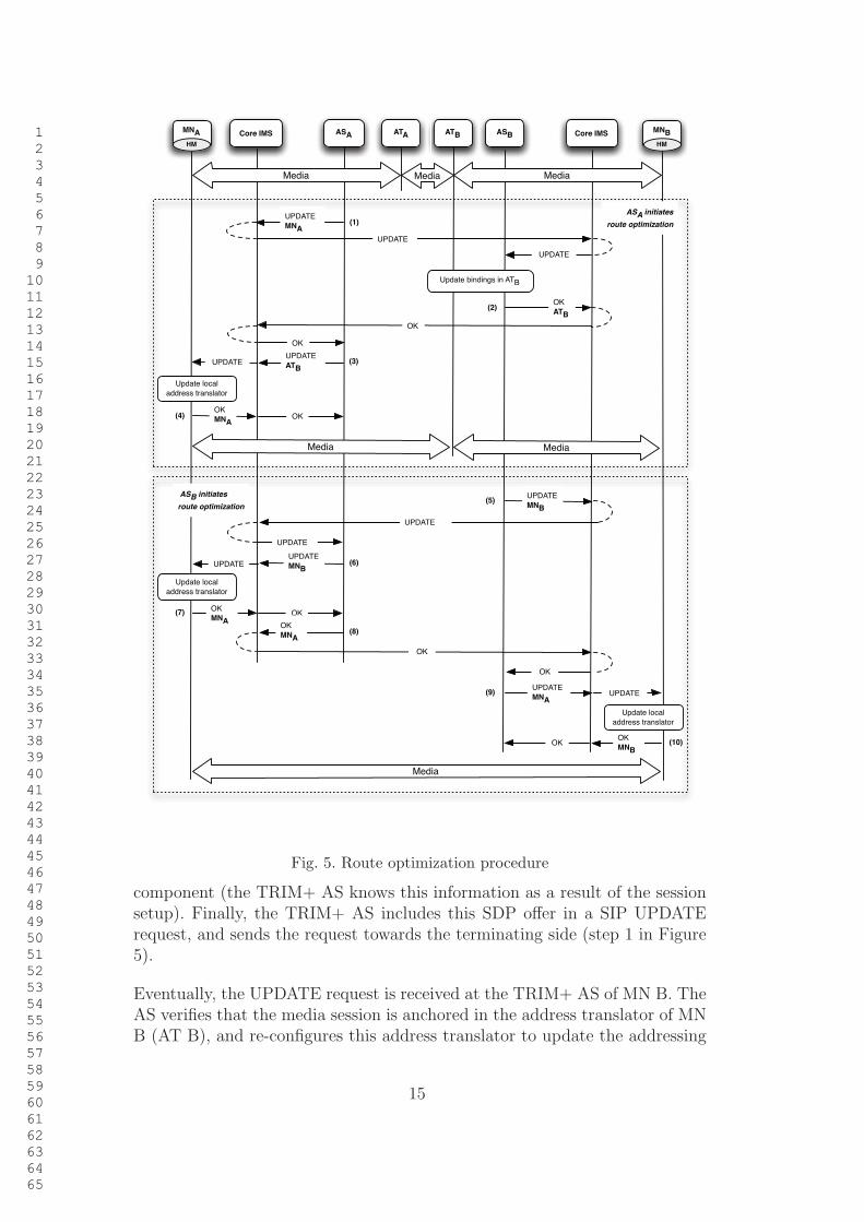
3.3 Transparent route optimization
Once the session has been established between the originating and terminatingUEs, route optimization procedures can be executed. In TRIM+, these proce-dures are started individually by each TRIM+ AS. However, it is important tounderstand that a TRIM+ AS can only initiate route optimization proceduresif its SIP peers in the IMS session have indicated that they support TRIM+,by means of the trim feature parameter.
Figure 5 shows the route optimization procedures that have been defined inthis paper. The figure assumes that two TRIM+ MNs, A and B, have com-pleted the IMS session setup procedures, therefore the media session is initiallyanchored by the address translators of both MNs.
In the figure we assume, without loss of generality, that the TRIM+ AS cor-responding to MN A initiates the route optimization procedures. To do that,the AS generates a new SDP offer to update the session that the AS has es-tablished with its SIP peer in the terminating side. This offer contains, foreach media component in the session (e.g. audio or video), the addressinginformation (i.e. IP address and port) where MN A is willing to receive the
14
1
2
3
4
5
6
7
8
9
10
11
12
13
14
15
16
17
18
19
20
21
22
23
24
25
26
27
28
29
30
31
32
33
34
35
36
37
38
39
40
41
42
43
44
45
46
47
48
49
50
51
52
53
54
55
56
57
58
59
60
61
62
63
64
65
UPDATE
MNA
Core IMS ASA ASB
UPDATE
OK
MNAOK
UPDATE
UPDATE
ATB
OK
(3)
(1)
Core IMS
UPDATE
OK
ATB
OK
(2)
(4)
UPDATE
MNB
UPDATE
UPDATE
UPDATE
MNAUPDATE
OK
MNBOK
UPDATEUPDATE
MNB
(9)
OK
MNAOK
OK
OK
MNA
OK
(5)
(10)
(6)
(7)
(8)
ASA initiates
route optimization
ASB initiates
route optimization
ATA ATB
Media
Update bindings in ATB
Media
Media
Media MediaMedia
MNB
HM
MNA
HM
Update local
address translator
Update local
address translator
Update local
address translator
Fig. 5. Route optimization procedure
component (the TRIM+ AS knows this information as a result of the sessionsetup). Finally, the TRIM+ AS includes this SDP offer in a SIP UPDATErequest, and sends the request towards the terminating side (step 1 in Figure5).
Eventually, the UPDATE request is received at the TRIM+ AS of MN B. TheAS verifies that the media session is anchored in the address translator of MNB (AT B), and re-configures this address translator to update the addressing
15

1
2
3
4
5
6
7
8
9
10
11
12
13
14
15
16
17
18
19
20
21
22
23
24
25
26
27
28
29
30
31
32
33
34
35
36
37
38
39
40
41
42
43
44
45
46
47
48
49
50
51
52
53
54
55
56
57
58
59
60
61
62
63
64
65
information corresponding to the originating side of the media session. Fromthis moment, data traffic coming from MN B to the address translator isdirectly addressed to MN A. The AS answers back the UPDATE request witha SIP OK response (step 2 in Figure 5). This response carries an SDP answer,although it does not include new changes to the session description.
Note that the change in the configuration of AT B may lead to transient packetreordering. This is because packets in transit that were transmitted before thechange will follow the route via AT A, which will typically impose a higherdelay than the direct route from AT B to MN A (i.e., the new route afterthe change). This situation may potentially arise after changing the config-uration of any of the address translators used in our proposal. However, wewant to highlight that packet reordering is a common issue in the execution ofapplications that operate over packet networks, and this situation is typicallyhandled at the transport layer (in case that TCP is used) or at the appli-cation layer (e.g. if UDP is used). Additionally, we want to emphasize thatour solution does not introduce duplicate packets or packet loss due to anychange on the configuration of an address translator. Packets arriving to anaddress translator are simply forwarded to the appropriate destination afterthe change.
When the OK response reaches the TRIM+ AS of MN A, the AS generates anew SDP offer to update the session leg corresponding to MN A. In this case,each media component in the offer includes the addressing information (i.e. IPaddress and port) corresponding to the address translator in the home networkof MN B (the TRIM+ AS learned this information from the previous SIPsignaling exchange with the terminating side). The TRIM+ AS encapsulatesthe SDP offer in a new SIP UPDATE request, which is sent within the dialogmaintained with MN A (step 3 in Figure 5). Note that this request could havebeen sent in parallel to the first SIP UPDATE, as the TRIM+ AS of MN A hasalready obtained the addressing information corresponding to the terminatingside during the session setup procedures. Nevertheless, the design of TRIM+processes these two UPDATE transactions sequentially, one after the other,this way ensuring that the remote side has processed the route optimizationbefore updating the leg of the MN. This prevents undesirable situations whereone of the peers of the TRIM+ AS fails to do the route optimization whilethe other succeeds. This may happen, for instance, when the TRIM+ AS of Breceives the UPDATE request but has already started the execution of its ownroute optimization mechanisms and thus, it has already sent a SIP UPDATErequest to the TRIM+ AS of MN A. According to [30], as both UPDATEScontain an SDP offer, the TRIM+ AS of B must reject the request with a 491failure response.
At some point, MN A receives the UPDATE request from the TRIM+ AS.Within the MN, the Handover Manager (HM) receives the session update
16
1
2
3
4
5
6
7
8
9
10
11
12
13
14
15
16
17
18
19
20
21
22
23
24
25
26
27
28
29
30
31
32
33
34
35
36
37
38
39
40
41
42
43
44
45
46
47
48
49
50
51
52
53
54
55
56
57
58
59
60
61
62
63
64
65
request along with the corresponding SDP offer. The HM verifies that theSDP offer only specifies a change in the addressing information correspondingto the media components, and thus the session update can be done without theintervention of any IMS communication service or application. Consequently,the HM updates the configuration of the local address translator at the MN,to reflect the new addressing information where the media should be delivered(i.e. the address translator in the home network of MN B). Then, the HMgenerates an SDP answer to the offer, which does not include new changes tothe session description. This answer is encapsulated in a SIP OK response tothe UPDATE request, which is routed back to the TRIM+ AS (step 4 in Fig.5).
At this point, the TRIM+ AS of MN A has concluded the route optimizationprocedures, which have been executed transparently to end-user applicationsat MN A. Data traffic is now directly exchanged between MN A and theaddress translator of MN B. Therefore, the media session is no longer anchoredby the address translator in the home network of MN A, which has beenextracted from the data path.
The route optimization procedures executed by the TRIM+ AS of MN Bproceed in a similar way. Consequently, AT B is removed from the data path.Data traffic is now directly exchanged between mobile nodes, following theshortest communication path between them.
The proposed mechanisms for route optimization allow each home operatorto implement its own policies to independently decide if these mechanismsshould be triggered and, in case they are, the specific instant to begin theirexecution. Nevertheless, it may always happen that both operators initiatethe route optimization procedures within the same time period. This can leadto situations where a TRIM+ AS receives an UPDATE request while it isstill waiting for a response to its own UPDATE request. According to [30],as both UPDATES contain an SDP offer, the AS must reject the UPDATEreceived from the remote peer with a SIP 491 failure response. After receiv-ing 491 response, the AS starts a timer and, when this timer fires, attemptsthe UPDATE transaction again. In [30], a specific mechanism is described tochoose the values for the timers corresponding to both ends of a SIP dialog.Therefore, even in the case where both operators initiate the route optimiza-tion procedures within the same time period, and both TRIM+ ASs rejectthe UPDATE request received from their SIP counterpart, timers eventuallyallow route optimization to be successfully completed.
A common case where this may happen is when the operator policy dictatesto start the route optimization procedures when the SIP ACK request, cor-responding to the session setup, is received at the TRIM+ AS (i.e. just afterfinishing the session establishment). In this case, both TRIM+ ASs start route
17

1
2
3
4
5
6
7
8
9
10
11
12
13
14
15
16
17
18
19
20
21
22
23
24
25
26
27
28
29
30
31
32
33
34
35
36
37
38
39
40
41
42
43
44
45
46
47
48
49
50
51
52
53
54
55
56
57
58
59
60
61
62
63
64
65
optimization synchronously, thus creating a possibility for parallel UPDATErejection that would increase the signaling overhead and delay the optimiza-tion process. To deal with this specific situation, in the design of TRIM+we include a set of recommendations related with the initiation of route op-timization procedures. In particular, the TRIM+ AS in the originating sideof the session can start the route optimization procedures right after sendingthe SIP ACK request towards the terminating side. When the TRIM+ ASlocated in the terminating side receives this ACK request, it starts a timerwith a value randomly chosen between 0 and T seconds. When this timer ex-pires, the terminating AS can start the route optimization procedures. Thisrecommendation aims at preventing both ends from synchronously beginningthe execution of the optimization mechanisms. Values of T can be chosen byoperators according to their own policies
Finally, the route optimization procedures described in this section are stillvalid when the communication takes place between a TRIM+ MN and aTRIM+ enabled UE connected to a fixed access network. The only differ-ence in this scenario is that route optimization does not involve a TRIM+ ASin the home network of the fixed UE.
3.4 Transparent handover management
Figure 6 illustrates the different scenarios of handover management, assumingthat a MN has previously established a multimedia session with a CN. Forsimplicity, we assume that communicating parties do not need to perform aresource reservation.
Independently of the handover scenario, the MN obtains IP access connectivityin the new IP Connectivity Access Network (IP-CAN). As a result of this, itacquires an IP address in the new network, as well as the IP address of a P-CSCF (if a new P-CSCF is to be used). Then, the IMS stack and the HM aretriggered from the lower layers 3 (see Figure 3). This way, the IMS stack canregister the new contact URI of the user, reflecting the current IP address,in the core IMS. Next, the HM retrieves the information corresponding tothe active IMS sessions that are exchanging user traffic through the interfaceinvolved in the handover. For each of these sessions, the HM generates anew SDP offer containing the new addressing information associated withthe interface (i.e. its current IP address). Then, the HM uses the IMS stackto update each affected multimedia session according to the new SDP offer,by means of an INVITE request. This request is routed to AS A, as thisis the anchor point at the signaling level to support the mobility of MN A.
3 Note that the direct support of link layer triggers is already present in technologiessuch as IEEE 802.11 as defined in the IEEE 802.11u amendment.
18

1
2
3
4
5
6
7
8
9
10
11
12
13
14
15
16
17
18
19
20
21
22
23
24
25
26
27
28
29
30
31
32
33
34
35
36
37
38
39
40
41
42
43
44
45
46
47
48
49
50
51
52
53
54
55
56
57
58
59
60
61
62
63
64
65
INVITE
trim, MNA
Case a
TRIM+ is not supported by CN
INVITE
OK
trim, ATAOK
ACK ACK
Media over new IP-CAN Media
Update bindings in ATA
Case b
CN is a TRIM+ MN
UPDATE
MNAUPDATE
UPDATE
UPDATE
MNAUPDATE
OK
CNBOK
CNBOK
OK
Update local
address translator
OK
trim, CNBOK
ACK ACK
Media over new IP-CAN
Case c
CN is a TRIM+ fixed UEUPDATE
MNAUPDATE UPDATE
OK
CNBOK
OK
Update local
address translator
OK
trim, CNB
OK
ACK ACK
Media over new IP-CAN
Obtain IP access
connectivity in
the new IP-CAN
IMS level registration
Core IMSMNA ASA ASB Core IMSATAHM
CNB
HM
Fig. 6. Transparent mobility management procedure
Handover management procedures differ from this point, depending on thefunctionalities supported by the CN.
In the first scenario (case a in Fig. 6), TRIM+ is not supported by the ter-minating side. In this situation, the TRIM+ AS of MN A updates the newaddressing information corresponding to the MN in the address translator(ATA), and completes the SIP signaling exchange with the mobile node. The
19

1
2
3
4
5
6
7
8
9
10
11
12
13
14
15
16
17
18
19
20
21
22
23
24
25
26
27
28
29
30
31
32
33
34
35
36
37
38
39
40
41
42
43
44
45
46
47
48
49
50
51
52
53
54
55
56
57
58
59
60
61
62
63
64
65
terminating leg of the communication is not affected in the signaling plane(TRIM+ AS to CN) nor in the data plane (address translator to CN).
In the second scenario (case b in Fig. 6), the CN is a TRIM+ MN. In thefigure, we assume that the route between the MN and the CN has alreadybeen optimized, following the procedures presented in the previous section.Therefore, the handover of the MN requires the IMS session in the terminatingside to be updated with the new addressing information corresponding to MNA. This guarantees that the communication between MN A and CN B cancontinue using the optimal route between them. Therefore, the TRIM+ AS ofMN A generates a new SDP offer to update the remote leg of the multimediasession at CN B. The offer indicates, for each media component (e.g. audioor video), the current addressing information (i.e. IP address and port) whereMN A will receive the component. The SDP offer is encapsulated in a SIPUPDATE request, which is routed to the TRIM+ AS in the terminating side.
As the session is not anchored in the terminating home network, this AS prop-agates the UPDATE request to the CN. The HM at CN B receives the requestto update the session according to the SDP offer. As the session descriptionuniquely modifies the addressing information corresponding to the media com-ponents, the HM takes the responsibility of updating the multimedia sessiontransparently to end-user applications at the CN. Thus, it accesses to the con-figuration of the local address translator at CN B, and updates it to reflectthe current addressing information of MN A. Then, the HM generates an SDPanswer that does not include further changes to the session, and encapsulatesit in a SIP OK response, which is routed to the TRIM+ AS of CN B. In turn,the AS answers back the received UPDATE request with a new OK response,indicating the successful update of the session in the terminating side. Whenthis response is received by the TRIM+ AS of MN A, the outstanding INVITEtransaction is completed according to the regular IMS procedures.
The scenario where the correspondent node is a TRIM+ fixed UE (case c
in Fig. 6) proceeds similarly, although a TRIM+ AS is not involved in theterminating side.
3.5 Management of packet loss during handovers
In the presented mobility management procedures, if the MN is temporarilyable to receive media from the old access network during the handover proce-dure, then the disruption of the media exchange can be minimized. Nonethe-less, there are cases where maintaining the media exchange during a handovervia the old network is simply not possible. In these cases, commonly en-compassed under the denomination of hard handovers, packet loss due to MN
20

1
2
3
4
5
6
7
8
9
10
11
12
13
14
15
16
17
18
19
20
21
22
23
24
25
26
27
28
29
30
31
32
33
34
35
36
37
38
39
40
41
42
43
44
45
46
47
48
49
50
51
52
53
54
55
56
57
58
59
60
61
62
63
64
65
mobility may significantly affect the performance offered to end-user applica-tions.
The mobility management solution described in this paper addresses packetloss management in hard handover scenarios. To this end, TRIM+ enablesthe MN to request buffering capacity in its home network to temporarilystore incoming media traffic during the handover delay, which would other-wise be dropped. This solution, hereafter referred to as in-home buffering,allows storing the user traffic transmitted from the CN while the media pathis not established through the new access network. Once the MN successfullycompletes the handover procedures, the multimedia session with the CN isre-established, and buffered media is delivered to the MN.
In-home buffering is a general technique that could be applied to other ar-chitectures to improve handover performance (see Sect. 4), but it fits nicelyin our solution because we use existing nodes and signaling to implement thenew functionality. This technique is supported by TRIM+ transparently toany end-user applications running at the MN and the CN.
In particular, this solution may be particularly useful in the case of multi-media applications. Although the majority of these applications are tolerantto occasional packet loss, which can normally be concealed to the user, longinterruptions causing packets loss may negatively impact the user experience.Networked multimedia applications typically use an application-level buffer tostore incoming media (e.g. RTP packets). Arriving media is removed from thebuffer and rendered to the user after certain playout delay. This delay permitsaccommodating network jitter and ensuring that the majority of the packetsare received in time for playout.
In TRIM+, traffic addressed to the MN during the handover is buffered in itscorresponding home network (this traffic would otherwise be dropped). How-ever, a multimedia application in the MN can still maintain the continuousplayout of media using the data stored in its application-level buffer. If thisbuffer is not emptied by the application during the handover, data stored inthe home network may be quickly transferred to the MN once the handovercompletes. This data will be placed in the application-level buffer, which willbe rapidly restored to an appropriate state, and will be available to the appli-cation for playout.
Of course, there is always the possibility of longer handover delays that cannotbe accommodated with the application-level buffer. Even in this case, datapackets stored in the home network will promptly be delivered to the MN aftera successful handover. So, packet loss is reduced, as TRIM+ still preservesmedia that would otherwise be lost in the absence of in-home buffering.
Our buffering mechanism is illustrated in figures 7 and 8. In Fig. 7, we assume
21

1
2
3
4
5
6
7
8
9
10
11
12
13
14
15
16
17
18
19
20
21
22
23
24
25
26
27
28
29
30
31
32
33
34
35
36
37
38
39
40
41
42
43
44
45
46
47
48
49
50
51
52
53
54
55
56
57
58
59
60
61
62
63
64
65
(3) Transparent undo of route optimization
MESSAGE
OKOK
(2) Configure buffering in ATA
UPDATE
ATAUPDATE
UPDATE
ATAUPDATE
OK
CNBOK
CNBOK
OK
MESSAGE
HO info
Media over old IP-CAN
Start local
buffering in
local
address
translator
(5)
Buffering of IP
packets
Core IMSMNA ASA ASB Core IMSATAHM
CNB
HM
Update local
address translator
OK
Media
(1)
UPDATE
(4) In-home buffering
End-to-end
media
path is
disrupted
due to the
handover
of the MN
Fig. 7. Activating in-home buffering prior to handover
a hard handover scenario, where a MN with a single active interface needs tochange the IP Connectivity Access Network (IP-CAN) used for the commu-nication with a CN. The picture shows the procedures that are necessary inTRIM+ to set up in-home buffering prior to the handover of the MN. Beforethe handover is initiated, the Handover Manager (HM) in the MN is trig-gered from the lower layers (see Figure 3). As a consequence of this trigger,the HM issues a MESSAGE request that is addressed to the Public ServiceIdentity (PSI) of the TRIM+ service (step 1 in Fig. 7). The HM indicates inthe body of the request that a handover is to be initiated, and includes theinformation that is necessary to activate in-home buffering. In particular, thisinformation contains the IP address of the MN in the current IP-CAN. Addi-tional mobility-management data may also be included, such as informationabout the current access network and a description of the reasons triggeringthe handover. Eventually, as a result of evaluating initial-filter criteria at theS-CSCF, the MESSAGE request is delivered to the TRIM+ AS allocated tothe user of the MN, which immediately answers back the request with a SIPOK response.
Our architecture uses MESSAGE requests to transport the information thatis necessary to activate in-home buffering 4 . Although other mechanisms could
4 The SIP MESSAGE method is defined in [31], and its implementation is manda-tory in IMS terminals.
22
1
2
3
4
5
6
7
8
9
10
11
12
13
14
15
16
17
18
19
20
21
22
23
24
25
26
27
28
29
30
31
32
33
34
35
36
37
38
39
40
41
42
43
44
45
46
47
48
49
50
51
52
53
54
55
56
57
58
59
60
61
62
63
64
65
be used, such as the SIP event notification framework [32], the utilization ofMESSAGE requests brings important advantages. In first place, these typeof requests do not establish dialogs and do not require the periodic exchangeof SIP messages to activate in-home buffering. This way, resource utilizationon IMS CSCFs and TRIM+ application servers, caused by a potentially largenumber of MNs, is reduced. Secondly, MESSAGE request are stand-alonemessages, and thus they can be sent over any of the registered interfaces ofthe MN.
The TRIM+ AS is an intermediate element that participates in every sessionsetup originating and terminating in the MN. Therefore, it maintains up-to-date information about all the multimedia sessions involving the MN. Usingthis information and the content of the MESSAGE request, the TRIM+ ASdetermines the media components received by the MN that will be affectedby the handover (i.e. those using the IP address of the MN indicated in theMESSAGE request). Then, it configures the address translator assigned tothe MN within its home network to buffer incoming data packets from thesemedia components (step 2 in Fig. 7).
In the example shown in Fig. 7, we assume that the communication betweenthe MN and the CN is using the optimal media path. Therefore, the TRIM+AS contacts the CN to undo the route optimization (step 3 in Fig 7). As aresult of this procedure, any media packets transmitted from the CN, whichmay otherwise be dropped during the handover of the MN, are temporarilybuffered in its home network (step 4 in Fig. 7). It is important to note thatthe address translator buffering media traffic is an intermediary entity, whichsimply stores incoming IP packets until the MN completes the handover andthe media path is re-established through the new access network. Thus, it doesnot terminate the media path at the transport level (e.g. it does terminate aTCP connection in the data plane). Finally, we want to highlight that pro-cedures comprising step 3 are not necessary in case that the media path wasalready anchored in ATA.
We argue that in-home buffering provides a scalable solution to mitigate packetlosses in hard handover scenarios. As the communication with the MN is tem-porarily interrupted during the handover, the TCP media flows from the CNwill eventually stop the transmission of new packets, alleviating the demandof buffer space in the home network of the MN. This is because the addresstranslator in the home network simply stores TCP media coming from theCN, and does not acknowledge the reception of TCP segments, as this canonly be done by the other end of the TCP connection (i.e., the MN), whichis unavailable during the handover. On the other hand, UDP flows originat-ing from inelastic applications (e.g. real-time audio and video) will not reducetheir sending rate. Even in this case, the usage of buffer space in the home net-work is limited, as storage capacity is only needed for a short time period, i.e.
23
1
2
3
4
5
6
7
8
9
10
11
12
13
14
15
16
17
18
19
20
21
22
23
24
25
26
27
28
29
30
31
32
33
34
35
36
37
38
39
40
41
42
43
44
45
46
47
48
49
50
51
52
53
54
55
56
57
58
59
60
61
62
63
64
65
the handover delay. Additionally, we want to emphasize that in the TRIM+architecture, as it is illustrated in Fig. 2, the home network may include anumber of address translators (for scalability and redundancy reasons), eachserving a number of TRIM+ terminals. Therefore, buffering demands causedby the handover of MNs are distributed.
Anyway, in those cases where this distribution is insufficient, and a number ofconcurrent handovers leads to buffer space exhaustion in an address translator,a set of operator policies, configured in the TRIM+ AS and enforced in theaddress translator, may govern an appropriate distribution of the availablebuffer resources among competing MNs.
On the other hand, once the MN receives the SIP OK response to the MES-SAGE request, it can initiate the handover procedure to move to the newIP-CAN. These procedures are illustrated in Fig. 8. In addition, and depend-ing on the resources available at the MN, the HM may request from the localaddress translator to temporarily store the data packets transmitted by theMN during the handover (step 5 in Fig. 7). This would enable to mitigatepacket loss for outgoing traffic, which is generated by the applications run-ning at the MN, while the multimedia session with the CN is reestablishedvia the new IP-CAN.
Assuming that in-home buffering has been triggered (resulting in the initial
setup shown in Fig. 8), the MN obtains IP connectivity in the new IP-CANand completes the IMS level registration from the new access network (steps 1and 2 respectively in Fig. 8). Then, it executes the access transfer proceduresthat are necessary to re-establish the multimedia session with the CN via thenew IP-CAN (step 3 in Fig. 8). These procedures involve executing an INVITEtransaction with the TRIM + AS, to update the addressing information of theMN in the signaling and data paths. As result of this transaction, the TRIM+AS reconfigures the address translator assigned to the MN in the home networkwith the new addressing information, and media exchange between the MNand the CN is resumed through the address translator.
In TRIM+, once the access transfer procedures have been completed, bufferedpackets in the home network are transmitted at the maximum rate availablein the address translator (ATA in the example). As data transmission from theCN is buffered during a reasonably short time (i.e. the handover delay), weassume that the new IP-CAN is able to process the traffic load correspondingto the buffered packets after re-establishing the session. Although we believethat this will be the common situation, there may be scenarios where thisassumption does not hold. In particular, inelastic UDP applications (e.g. real-time audio and video), facing high handover delays, may introduce a high loadof buffered traffic that exceeds the capacity allocated in the access network.Even in this case, where packets may be dropped, our solution can mitigate
24

1
2
3
4
5
6
7
8
9
10
11
12
13
14
15
16
17
18
19
20
21
22
23
24
25
26
27
28
29
30
31
32
33
34
35
36
37
38
39
40
41
42
43
44
45
46
47
48
49
50
51
52
53
54
55
56
57
58
59
60
61
62
63
64
65
INVITE
trim, MNAINVITE
OK
trim, ATAOK
ACK ACK
UPDATE
CNBUPDATE
OK OK
Media & buffered media over new IP-CAN Media & buffered media
(1) Obtain IP
access connectivity
in the new IP-CAN
(2) IMS level registration
Update bindings in ATA and
start media delivery to MNA
(3) Access transfer
(4) Transparent route optimizationUPDATE
ATAUPDATE
UPDATE
UPDATE
ATAUPDATE
OK
CNBOK
CNBOK
OK
Media over new IP-CAN
Core IMSMNA ASA ASB Core IMSATAHM
CNB
HM
Update local
address translator
OK
Local
buffering
Buffering of
IP packetsInitial setup Media
Fig. 8. Mobility management and recovery of buffered media
packet loss to the extent enabled by the underlying IP-CAN.
Finally, if TRIM+ is supported by the CN, the TRIM+ AS of the MN canre-establish the optimal route via the new IP-CAN (step 4 in Fig. 8).
4 Evaluation of the proposal
This section focuses on the evaluation of the mobility management solutionthat has been presented in this paper. As a proof-of-concept, we have imple-mented a software prototype of the TRIM+ architecture. This prototype has
25

1
2
3
4
5
6
7
8
9
10
11
12
13
14
15
16
17
18
19
20
21
22
23
24
25
26
27
28
29
30
31
32
33
34
35
36
37
38
39
40
41
42
43
44
45
46
47
48
49
50
51
52
53
54
55
56
57
58
59
60
61
62
63
64
65
been deployed over an evaluation testbed, which has been built using virtualmachines. By using this testbed, we conducted several experiments allowingto validate the proposal presented in this paper.
In Sect. 4.1 we describe the evaluation testbed. In Sect. 4.2, we demonstratethe appropriate operation of our architecture, assuming UDP media communi-cations in the data plane. The validation considering TCP media communica-tions is included in Sect. 4.3. In Sect. 4.4 we show the performance advantagesof using in-home buffering both for UDP and TCP traffic. Finally, in Sect. 4.5,we provide some considerations about the performance that can be achievedby TRIM+, emphasizing the advantages of this proposal with respect to thearchitecture developed by 3GPP for the delivery of IMS Service Continuity[26].
4.1 Evaluation testbed
To validate TRIM+ and to demonstrate a real implementation of our proposal,we have implemented a software prototype of the TRIM+ architecture includ-ing all the functional entities presented in Figure 2, i.e., a TRIM+ ApplicationServer (AS), an address translator and a TRIM+ UE (including the modulesdepicted in Fig.3). The implementation was written in Java, using the JavaJAIN-SIP API 5 for the SIP modules, and includes the different functionalitiesrelated with session setup (Sect. 3.2), transparent route optimization (Sect.3.3) and handover management (Sect. 3.4). To implement address translationfunctionalities, both in the network and in the UE, we used the Click! modularrouter platform 6 .
We deployed the software prototype of the TRIM+ architecture in a testbedof virtual machines, using a physical machine running the VMWare ESXi 7
virtualization software. The evaluation testbed includes a real IMS core, inparticular, the Fokus Open IMS core 8 , which allowed us to verify the appro-priate execution of all the IMS signaling procedures of TRIM+. Note that nomodifications were needed to the IMS core, as they are not required in ourproposal. We also included two TRIM+ mobile nodes, MNA and MNB. Inour experiments, ASA is the TRIM+ AS that anchors the signaling sessionsof MNA, while ATA is the address translator that will be used in MNA homenetwork. Similarly, ASB and ATB are respectively the TRIM+ AS and theaddress translator that will be utilized for MNB.
5 JAIN SIP Developer Tools, http://jain-sip.dev.java.net/6 http://www.read.cs.ucla.edu/click/click/7 http://www.vmware.com/8 http://www.openimscore.org/
26
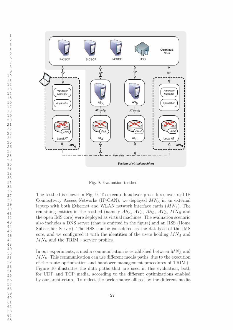
1
2
3
4
5
6
7
8
9
10
11
12
13
14
15
16
17
18
19
20
21
22
23
24
25
26
27
28
29
30
31
32
33
34
35
36
37
38
39
40
41
42
43
44
45
46
47
48
49
50
51
52
53
54
55
56
57
58
59
60
61
62
63
64
65
Open IMS
Core
HSSP-CSCF S-CSCF I-CSCF
ATA
ATB
ASA
ASB
MNA
SIP SIP SIP
AT config AT config
SIP
Local AT
User data
System of virtual machines
MNB
Handover
Manager
Application
Handover
Manager
Application
Click!
Local AT
Click! Click! Click!
Fig. 9. Evaluation testbed
The testbed is shown in Fig. 9. To execute handover procedures over real IPConnectivity Access Networks (IP-CAN), we deployed MNA in an externallaptop with both Ethernet and WLAN network interface cards (MNA). Theremaining entities in the testbed (namely ASA, ATA, ASB, ATB, MNB andthe open IMS core) were deployed as virtual machines. The evaluation scenarioalso includes a DNS server (that is omitted in the figure) and an HSS (HomeSubscriber Server). The HSS can be considered as the database of the IMScore, and we configured it with the identities of the users holding MNA andMNB and the TRIM+ service profiles.
In our experiments, a media communication is established between MNA andMNB. This communication can use different media paths, due to the executionof the route optimization and handover management procedures of TRIM+.Figure 10 illustrates the data paths that are used in this evaluation, bothfor UDP and TCP media, according to the different optimizations enabledby our architecture. To reflect the performance offered by the different media
27

1
2
3
4
5
6
7
8
9
10
11
12
13
14
15
16
17
18
19
20
21
22
23
24
25
26
27
28
29
30
31
32
33
34
35
36
37
38
39
40
41
42
43
44
45
46
47
48
49
50
51
52
53
54
55
56
57
58
59
60
61
62
63
64
65
Path A: 400 ms
Path B: 100 ms
Path C: 0 ms
Path D: 0 ms
ATA
ATB Local ATLocal AT
Application Application
MNA MNB
System of virtual machines
RTTs in the system of Virtual machines
Click! Click! Click! Click!
Fig. 10. Media paths in the communication between MNA and MNB
paths, each was configured with a given round-trip delay within the system ofvirtual machines (these delays are also shown in the figure). Nonetheless, it isimportant to note that the actual end-to-end delay, for any of the consideredmedia paths, also depends on the network delay from the physical machinerunning the VMWare to the laptop deploying MNA (that may be via Ethernetor WLAN).
The round trip delays were enforced in our testbed using the Click! software.The configuration of Click! is based on the interconnection of different ele-ments, which are pieces of code that implement a certain functionality. In ourcase, the configuration of each address translator (ATA, ATB and the localtranslators at MNA and MNB) has three different parts: first, the incomingtraffic is classified based on the transport ports (source or destination) con-tained in the packets; the selected output of such classifier is connected to aDelayShaper element, which delays the transmission of incoming packets by aconfigurable time; finally, the packet headers are rewritten in order to properlychange the addressing information.
4.2 Validation of UDP media communications
In this section, we assume that communications taking place in the user planeare based on UDP. In our experiment, MNA and MNB first register in theIMS core. Then, MNA starts a session setup towards MNB using the IMScore, following the signaling exchange presented in case b of Fig. 4. When thesession is established, a client application based on iperf, running at MNB,starts sending UDP traffic towards an iperf server application, which runs atMNA at a rate of 1 Mbps. According to TRIM+ procedures, UDP packets areinitially delivered to MNA via a suboptimal data path that traverses ATB and
28

1
2
3
4
5
6
7
8
9
10
11
12
13
14
15
16
17
18
19
20
21
22
23
24
25
26
27
28
29
30
31
32
33
34
35
36
37
38
39
40
41
42
43
44
45
46
47
48
49
50
51
52
53
54
55
56
57
58
59
60
61
62
63
64
65
ATA (i.e., data path A in Fig. 10). In our software prototype, we configuredASA to start the route optimization procedures approximately 20 seconds afterthe session setup, using the signaling exchange illustrated in Fig. 5. As a resultof these procedures, ATA is extracted from the data path and UDP packetsare delivered to MNA through ATB (i.e. using data path B in Fig. 10). On theother hand, ASB waits for 40 seconds to start route optimization, which takeplace according to Fig. 5. Once the data path optimization concludes, trafficis delivered directly from MNB to MNA (i.e. using data path C in Fig. 9).
After some time, we manually initiate a handover from the Ethernet to theWLAN access network. As a result of this, the IMS stack and the handovermanager (HM), implemented at MNA are triggered. This way, the IMS stackinitiates a new IMS level registration, updating the location of the MN in thecore IMS (now it is available in the WLAN access network). Then, the HMat MNA re-establishes the multimedia session via the WLAN IP-CAN, byexecuting the signaling exchange shown in case b of Fig. 6. To avoid packetlosses, the configuration ofMNA is changed to start using the wireless interfacewhile the Ethernet is still receiving media. Once the session is re-established,MNA starts receiving UDP packets via de WLAN interface (path D in Fig. 5).
It is important to remark that the iperf applications running at MNB andMNA are launched when the IMS session is established, and route optimizationand handover management are completely transparent to these applications.This is enabled by the handover manager running at each mobile node, whichchanges the configuration of its local address translator to conceal any changeon the addressing information to the end user application (i.e. iperf client andserver).
Figure 11 shows the throughput of the UDP traffic, transmitted from the iperfserver at MNB and measured at MNA. The figure shows the traffic that isreceived through paths A, B, C an D. Note that although TRIM+ makes routeoptimization and handover procedures transparent to the end-user applicationrunning at MNA, it was possible to distinguish these sub-graphs using theWireshark 9 network packet analyzer listening at the any interface of MNA.
4.3 Validation of TCP media communications
This section focuses on validating the proposed solution assuming that mediacommunications are based on TCP. To provide a realistic scenario, where TCPtraffic exchanged between MNA and MNB competes with other traffic flowsfor the available bandwidth, we limited the bandwidth on the network pathconnecting MNA with the system of virtual machines to 10 Mbps. In addition,
9 http://www.wireshark.org/
29

1
2
3
4
5
6
7
8
9
10
11
12
13
14
15
16
17
18
19
20
21
22
23
24
25
26
27
28
29
30
31
32
33
34
35
36
37
38
39
40
41
42
43
44
45
46
47
48
49
50
51
52
53
54
55
56
57
58
59
60
61
62
63
64
65
0
200
400
600
800
1000
1200
1400
0 10 20 30 40 50 60 70 80 90
Thro
ughput
(kbps)
relative time (sec)
Data path AData path BData path C
Data path D (WiFi)
Fig. 11. Route optimization and handover of an UDP flow
we configured a continuous background traffic through that network path,by setting a TCP bulk data transmission with the iperf tool. This allowedmeasuring the benefits of the optimization in terms of throughput.
For the experiment, we followed the same steps as in the validation of UDPmedia communications (see Sect. 4.2): we established an IMS session betweenMNA and MNB; we set a TCP transmission from MNB to MNA using theiperf application; we configured the execution of route optimization proce-dures after the same time periods; and we executed a handover of MNA fromthe Ethernet to the WLAN access network. In order to present the results,in Figure 12 we show the Sequence number and Throughput vs Time graphobtained as the result of the complete experiment.
Focusing on the graph of the sequence number, it can be seen how the slope ofthe curve is different for each of the data paths taken by the flow (i.e., paths A,B, C and D). This behavior is due to the inverse relation of TCP throughputwith the round trip delay of the path. Following this idea, it can be seen howthe part of the graph corresponding to path C (the one with smaller delay) isthe one with a stepper slope. It is worth to notice, that the handover and thechanges of path for this experiment do not cause packet loss, as old paths aremaintained active to deliver outstanding traffic in transit.
This analysis shows experimentally how the use of our optimization proce-dures has a positive impact on the throughput achievable by TCP, while alsoreducing the RTT, without requiring the re-establishment of TCP connections.Hence its use is beneficial, specially in environments where the delay betweenthe ATs is very high or when the MNs are far away from their correspondingAT.
30

1
2
3
4
5
6
7
8
9
10
11
12
13
14
15
16
17
18
19
20
21
22
23
24
25
26
27
28
29
30
31
32
33
34
35
36
37
38
39
40
41
42
43
44
45
46
47
48
49
50
51
52
53
54
55
56
57
58
59
60
61
62
63
64
65
�
�
��
��
��
��
��
����� ����� ����� ����� ����� ����� ����� ����� ����� ������
�
�
�
�
�
�
�� ����
��������
����
����
���
���
����
����� !� � "�
�� ���� � "���#!����� ���� ��� �
��� ��"���� �!����� ���� ��� �
�����������
�����������
����������
�������������� ��
Fig. 12. Sequence number and Throughput vs Time
4.4 Performance analysis of in-home buffering
Once we have validated our mobility management proposal and its route op-timization mechanism, in this section we turn our attention to analyze thebenefits in terms of performance that can be achieved with in-home bufferingin the data plane. In order to show the benefits of using a buffering mecha-nism instead of discarding packets, two different scenarios have been tested:(i) a constant bit-rate flow generated by means of iperf and (ii) a file transfer.While in the former, both UDP and TCP transport protocols where used, inthe latter just TCP was tested. Both scenarios share the same testbed alreadyused in Sec. 4.1 and depicted in Fig. 9, maintaining the bandwidth limita-tion of 10 Mbps in the network path from the system of virtual machines toMNA. In all these experiments, the MNA acts as the receiver so, ATA willbe configured to buffer packets, when the buffering is activated or to discardpackets if it is not. We always use the suboptimal path via ATA with a con-figured RTT of 30 ms. The Click! modular router that we use to implementaddress translation also allows us to introduce the buffering functionality. Inparticular, the buffering function is implemented as a Queue connected to anUnqueue element, used to pull packets from the queue: when the buffering is
31

1
2
3
4
5
6
7
8
9
10
11
12
13
14
15
16
17
18
19
20
21
22
23
24
25
26
27
28
29
30
31
32
33
34
35
36
37
38
39
40
41
42
43
44
45
46
47
48
49
50
51
52
53
54
55
56
57
58
59
60
61
62
63
64
65
active, the Unqueue element is inactive, so all received packets are stored atthe buffer. As soon as the buffering receives the proper signal, the Unqueue
element is activated again, so it starts pulling the queue at the maximumavailable rate. In case of discarding, the Unqueue element sends its output toa discard element.
In the first scenario, an instance of iperf is configured as a server at MNA, soit can receive a 1Mbps traffic generated by an iperf client running at MNB,through ATA. In case of UDP traffic, iperf allows configuring the transmissionrate. In the TCP case, this rate limitation was enforced at MNB using thetc tool 10 . In order to simulate a handover, after approximately 4 seconds 11 ,ATA is configured to buffer or discard packets for 1 second. The results forTCP are shown in Fig. 13, while Fig. 14 presents the results for UDP. In theTCP experiments, the figures show the segments received versus time and, asit can be seen in Fig. 13(a), the gap when the buffering is not active is higherthan one second. This is because the RTO (retransmission timeout) at MNB
has increased as no ACKs have been received for one second of interruption.The zoom area inside the figure, depicting the first packets received just afterthe interruption, shows that MNB restarts transmission using the TCP slowstart algorithm. On the other hand, as shown in Fig. 13(b), when the bufferingmechanism is active, the extra interruption time is lower. The explanation isthis behavior is the following: as soon as the ATA receives the order to transmitthe packets stored at the buffer, it uses the maximum available bandwidth totransmit all of them. Eventually, those packets will be received by MNA,which generates the corresponding ACKs packets, allowing MNB to continuethe paused transfer (TCP pauses the transmission during the interruptionbecause it is not receiving ACKs). In this case, the first packets receivedafter the interruption are the ones stored at the ATA buffer, as shown in thezoom area of Fig. 13(b). The packets in the buffer are not only recoveredpackets, they also allow to bootstrap the TCP connection opening the TCPtransmission window in MNB.
The main difference between UDP and TCP is that in the former, all packetsdiscarded do not arrive to the destination, as shown in Fig.14(a). In case buffer-ing is used, all packets stored at the queue are transmitted at the maximumavailable bandwidth after the interruption so, as it can be seen in Fig.14(b),they are recovered very quickly after the interruption with no packet loss.
The second scenario, as stated before, includes a file transfer between the twomobile nodes. This scenario is intended to provide an idea about how longit takes to recover after an interruption. In this case, MNA is downloading a
10 http://www.linuxfoundation.org/collaborate/workgroups/networking/netem11 This value was chosen so that the time period from the beginning of the experi-ment was enough to reach the target rate of the iperf source, i.e., 1 Mbps.
32

1
2
3
4
5
6
7
8
9
10
11
12
13
14
15
16
17
18
19
20
21
22
23
24
25
26
27
28
29
30
31
32
33
34
35
36
37
38
39
40
41
42
43
44
45
46
47
48
49
50
51
52
53
54
55
56
57
58
59
60
61
62
63
64
65
(a) Discarding
4.5
5.5
6.5
7.5
4 5 6 7 8 9
Sequence o
ffset
x 1
e6
Time (s)
1s SegmentsACKs
4.8
5
6.6 6.7
(b) Buffering
4.5
5.5
6.5
7.5
8.5
4 5 6 7 8 9
Sequence o
ffset
x 1
e6
Time (s)
1sSegments
ACKs
4.8
5
5.6 5.7
Fig. 13. TCP results
2MBytes file stored at MNB, through ATA. Similarly to the previous scenario,the flow corresponding to the file transfer is limited to 1Mbps. Four differentinterruption times, representing handover delays, are provided: 0s (i.e., nointerruption), 400ms, 1s and 3s. 400ms has been chosen because it is the max-
33

1
2
3
4
5
6
7
8
9
10
11
12
13
14
15
16
17
18
19
20
21
22
23
24
25
26
27
28
29
30
31
32
33
34
35
36
37
38
39
40
41
42
43
44
45
46
47
48
49
50
51
52
53
54
55
56
57
58
59
60
61
62
63
64
65
imum end-to-end delay for voice recommended by ITU-T [33]. One and threeseconds are used as upper bounds for real interruptions during a handover.For every single interruption time, 60 runs were executed, where the initialtime for the interruption follows a random variable with uniform distributionbetween 1 and 15 seconds. The results obtained are shown in Fig. 15, wherethe symbol marks represent the mean value of the executions and the arrowscentered at the mean show the 95% confidence interval for each value. Theseresults demonstrate the benefits of the buffering mechanism, specially for lowinterruptions, where the transfer time is similar to the values obtained withthe normal download process. Moreover, the buffering reduces the variance ofthe transfer time compared with the discarding process, where the transfertime strongly depends on the moment of the interruption.
(a) Discarding
0
1000
2000
3000
4000
5000
0 2 4 6 8 10 12 14
Rate
(kbps)
Time (sec)
(b) Buffering
0
1000
2000
3000
4000
5000
6000
0 2 4 6 8 10 12 14
Rate
(kbps)
Time (sec)
Fig. 14. UDP results
4.5 Considerations about performance
In this section, we provide a set of considerations about the performance thatcan be achieved by TRIM+, and we analyze the main benefits of this proposalwith respect to the architecture defined by 3GPP to maintain IMS ServiceContinuity (SC) in the event of terminal mobility [26]. Our analysis does notcover other solutions for mobility management that we describe in Sect. 2, asthese solutions cannot be directly integrated in IMS networks [8,10].
One of the main metrics that can be used to evaluate the performance of amobility management solution is the handover delay. In the following, weprovide an estimation of the handover delay that can be achieved by TRIM+,using an approach similar to [2]. Assuming that a mobile node (MN) is usinga given access network to exchange media traffic with a correspondent node(CN), we define the handover delay HOd as the time from the instant the MNstarts the attachment procedure to a new access network until it can receive
34
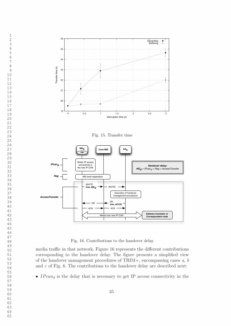
1
2
3
4
5
6
7
8
9
10
11
12
13
14
15
16
17
18
19
20
21
22
23
24
25
26
27
28
29
30
31
32
33
34
35
36
37
38
39
40
41
42
43
44
45
46
47
48
49
50
51
52
53
54
55
56
57
58
59
60
61
62
63
64
65
19
20
21
22
23
24
25
26
0 0.5 1 1.5 2 2.5 3
Tra
nsfe
r tim
e (
s)
Interruption time (s)
DiscardingBuffering
Fig. 15. Transfer time
INVITE
trim, MNA
Handover delay:
HOd = IPcand + Reg + AccessTransfer
INVITE
OK
trim, AT/CNOK
ACK ACK
Media over new IP-CAN
Execution of handover
management procedures
Obtain IP access
connectivity in
the new IP-CAN
IMS level registration
Core IMSMNA ASAHM
IPcand
Reg
AccessTransfer
Address translator or
Correspondent node
Fig. 16. Contributions to the handover delay
media traffic in that network. Figure 16 represents the different contributionscorresponding to the handover delay. The figure presents a simplified viewof the handover management procedures of TRIM+, encompassing cases a, band c of Fig. 6. The contributions to the handover delay are described next:
• IPcand is the delay that is necessary to get IP access connectivity in the
35
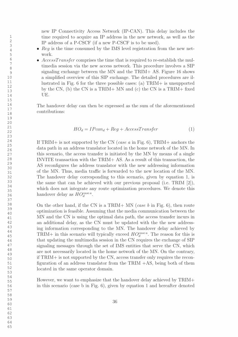
1
2
3
4
5
6
7
8
9
10
11
12
13
14
15
16
17
18
19
20
21
22
23
24
25
26
27
28
29
30
31
32
33
34
35
36
37
38
39
40
41
42
43
44
45
46
47
48
49
50
51
52
53
54
55
56
57
58
59
60
61
62
63
64
65
new IP Connectivity Access Network (IP-CAN). This delay includes thetime required to acquire an IP address in the new network, as well as theIP address of a P-CSCF (if a new P-CSCF is to be used).
• Reg is the time consumed by the IMS level registration from the new net-work.
• AccessTransfer comprises the time that is required to re-establish the mul-timedia session via the new access network. This procedure involves a SIPsignaling exchange between the MN and the TRIM+ AS. Figure 16 showsa simplified overview of this SIP exchange. The detailed procedures are il-lustrated in Fig. 6 for the three possible cases: (a) TRIM+ is unsupportedby the CN, (b) the CN is a TRIM+ MN and (c) the CN is a TRIM+ fixedUE.
The handover delay can then be expressed as the sum of the aforementionedcontributions:
HOd = IPcand +Reg + AccessTransfer (1)
If TRIM+ is not supported by the CN (case a in Fig. 6), TRIM+ anchors thedata path in an address translator located in the home network of the MN. Inthis scenario, the access transfer is initiated by the MN by means of a singleINVITE transaction with the TRIM+ AS. As a result of this transaction, theAS reconfigures the address translator with the new addressing informationof the MN. Thus, media traffic is forwarded to the new location of the MN.The handover delay corresponding to this scenario, given by equation 1, isthe same that can be achieved with our previous proposal (i.e. TRIM [2]),which does not integrate any route optimization procedures. We denote thishandover delay as HOcase a
d.
On the other hand, if the CN is a TRIM+ MN (case b in Fig. 6), then routeoptimization is feasible. Assuming that the media communication between theMN and the CN is using the optimal data path, the access transfer incurs inan additional delay, as the CN must be updated with the the new address-ing information corresponding to the MN. The handover delay achieved byTRIM+ in this scenario will typically exceed HOcase a
d. The reason for this is
that updating the multimedia session in the CN requires the exchange of SIPsignaling messages through the set of IMS entities that serve the CN, whichare not necessarily located in the home network of the MN. On the contrary,if TRIM+ is not supported by the CN, access transfer only requires the recon-figuration of an address translator from the TRIM +AS, being both of themlocated in the same operator domain.
However, we want to emphasize that the handover delay achieved by TRIM+in this scenario (case b in Fig. 6), given by equation 1 and hereafter denoted
36
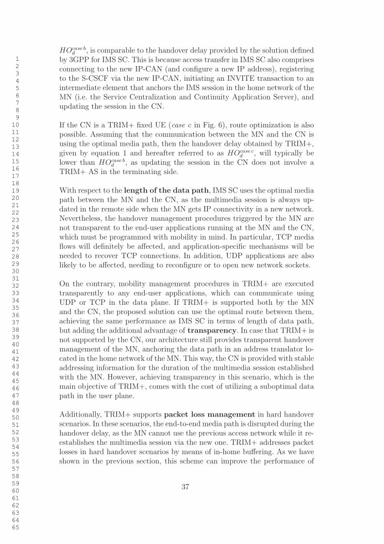
1
2
3
4
5
6
7
8
9
10
11
12
13
14
15
16
17
18
19
20
21
22
23
24
25
26
27
28
29
30
31
32
33
34
35
36
37
38
39
40
41
42
43
44
45
46
47
48
49
50
51
52
53
54
55
56
57
58
59
60
61
62
63
64
65
HOcase bd
, is comparable to the handover delay provided by the solution definedby 3GPP for IMS SC. This is because access transfer in IMS SC also comprisesconnecting to the new IP-CAN (and configure a new IP address), registeringto the S-CSCF via the new IP-CAN, initiating an INVITE transaction to anintermediate element that anchors the IMS session in the home network of theMN (i.e. the Service Centralization and Continuity Application Server), andupdating the session in the CN.
If the CN is a TRIM+ fixed UE (case c in Fig. 6), route optimization is alsopossible. Assuming that the communication between the MN and the CN isusing the optimal media path, then the handover delay obtained by TRIM+,given by equation 1 and hereafter referred to as HOcase c
d, will typically be
lower than HOcase bd
, as updating the session in the CN does not involve aTRIM+ AS in the terminating side.
With respect to the length of the data path, IMS SC uses the optimal mediapath between the MN and the CN, as the multimedia session is always up-dated in the remote side when the MN gets IP connectivity in a new network.Nevertheless, the handover management procedures triggered by the MN arenot transparent to the end-user applications running at the MN and the CN,which must be programmed with mobility in mind. In particular, TCP mediaflows will definitely be affected, and application-specific mechanisms will beneeded to recover TCP connections. In addition, UDP applications are alsolikely to be affected, needing to reconfigure or to open new network sockets.
On the contrary, mobility management procedures in TRIM+ are executedtransparently to any end-user applications, which can communicate usingUDP or TCP in the data plane. If TRIM+ is supported both by the MNand the CN, the proposed solution can use the optimal route between them,achieving the same performance as IMS SC in terms of length of data path,but adding the additional advantage of transparency. In case that TRIM+ isnot supported by the CN, our architecture still provides transparent handovermanagement of the MN, anchoring the data path in an address translator lo-cated in the home network of the MN. This way, the CN is provided with stableaddressing information for the duration of the multimedia session establishedwith the MN. However, achieving transparency in this scenario, which is themain objective of TRIM+, comes with the cost of utilizing a suboptimal datapath in the user plane.
Additionally, TRIM+ supports packet loss management in hard handoverscenarios. In these scenarios, the end-to-end media path is disrupted during thehandover delay, as the MN cannot use the previous access network while it re-establishes the multimedia session via the new one. TRIM+ addresses packetlosses in hard handover scenarios by means of in-home buffering. As we haveshown in the previous section, this scheme can improve the performance of
37
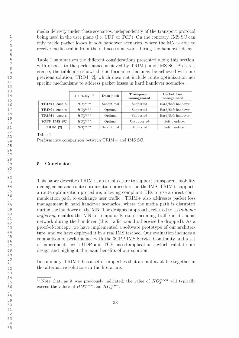
1
2
3
4
5
6
7
8
9
10
11
12
13
14
15
16
17
18
19
20
21
22
23
24
25
26
27
28
29
30
31
32
33
34
35
36
37
38
39
40
41
42
43
44
45
46
47
48
49
50
51
52
53
54
55
56
57
58
59
60
61
62
63
64
65
media delivery under these scenarios, independently of the transport protocolbeing used in the user plane (i.e. UDP or TCP). On the contrary, IMS SC canonly tackle packet losses in soft handover scenarios, where the MN is able toreceive media traffic from the old access network during the handover delay.
Table 1 summarizes the different considerations presented along this section,with respect to the performance achieved by TRIM+ and IMS SC. As a ref-erence, the table also shows the performance that may be achieved with ourprevious solution, TRIM [2], which does not include route optimization norspecific mechanisms to address packet losses in hard handover scenarios.
HO delay 12 Data path Transparentmanagement
Packet lossmanagement
TRIM+ case a HOcase a
dSuboptimal Supported Hard/Soft handover
TRIM+ case b HOcase b
dOptimal Supported Hard/Soft handover
TRIM+ case c HOcase c
dOptimal Supported Hard/Soft handover
3GPP IMS SC HOcase b
dOptimal Unsupported Soft handover
TRIM [2] HOcase a
dSuboptimal Supported Soft handover
Table 1Performance comparison between TRIM+ and IMS SC.
5 Conclusion
This paper describes TRIM+, an architecture to support transparent mobilitymanagement and route optimization procedures in the IMS. TRIM+ supportsa route optimization procedure, allowing compliant UEs to use a direct com-munication path to exchange user traffic. TRIM+ also addresses packet lossmanagement in hard handover scenarios, where the media path is disruptedduring the handover of the MN. The designed approach, referred to as in-home
buffering, enables the MN to temporarily store incoming traffic in its homenetwork during the handover (this traffic would otherwise be dropped). As aproof-of-concept, we have implemented a software prototype of our architec-ture and we have deployed it in a real IMS testbed. Our evaluation includes acomparison of performance with the 3GPP IMS Service Continuity and a setof experiments, with UDP and TCP based applications, which validate ourdesign and highlight the main benefits of our solution.
In summary, TRIM+ has a set of properties that are not available together inthe alternative solutions in the literature:
12 Note that, as it was previously indicated, the value of HOcase bd
will typicallyexceed the values of HOcase a
dand HOcase c
d.
38
1
2
3
4
5
6
7
8
9
10
11
12
13
14
15
16
17
18
19
20
21
22
23
24
25
26
27
28
29
30
31
32
33
34
35
36
37
38
39
40
41
42
43
44
45
46
47
48
49
50
51
52
53
54
55
56
57
58
59
60
61
62
63
64
65
(1) Its mobility support procedures are transparent to applications and cor-respondent nodes.
(2) It is compatible with legacy terminals, i.e., a TRIM+ terminal can com-municate with a standard 3GPP terminal or other terminals withoutTRIM+ functionality, and still have mobility support.
(3) It does not require modifications to the IMS infrastructure.(4) Its performance is comparable to that of the 3GPP IMS Service Continu-
ity in terms of communications end-to-end delay and handover delay, andit is better in terms of packet loss management during hard handovers.
Our future work includes exploring the potential of TRIM+ to handle thetransfer of a media session to a different terminal, and to support transparentmobility to legacy circuit switched networks.
Acknowledgements
This article has been partially granted by the Madrid Community through theMEDIANET project (S-2009/TIC-1468). The work of Ignacio Soto has beenpartially supported through the I-MOVING project (TEC2010-18907).
References
[1] 3GPP, IP Multimedia Subsystem (IMS); Stage 2, TS 23.228 version 11.7.0Release 11, TS 23.228, 3rd Generation Partnership Project (3GPP) (Jan. 2013).
[2] I. Vidal, A. de la Oliva, J. Garcia-Reinoso, I. Soto, TRIM: An architecture fortransparent IMS-based mobility, Computer Networks 55 (7) (2011) 1474–1486.
[3] J. Rosenberg, H. Schulzrinne, G. Camarillo, A. Johnston, J. Peterson, R. Sparks,M. Handley, E. Schooler, SIP: Session Initiation Protocol, RFC 3261, InternetEngineering Task Force (Jun. 2002).
[4] M. Handley, V. Jacobson, C. Perkins, SDP: Session Description Protocol, RFC4566, Internet Engineering Task Force (Jul. 2006).
[5] 3GPP, IP multimedia call control protocol based on Session Initiation Protocol(SIP) and Session Description Protocol (SDP); Stage 3, TS 24.229, 3rdGeneration Partnership Project (3GPP) (Jun. 2013).
[6] C. Perkins, IP Mobility Support for IPv4, RFC 3344, Internet Engineering TaskForce (Aug. 2002).
[7] C. Perkins, D. Johnson, J. Arkko, Mobility Support in IPv6, RFC 6275, InternetEngineering Task Force (Jul. 2011).
39
1
2
3
4
5
6
7
8
9
10
11
12
13
14
15
16
17
18
19
20
21
22
23
24
25
26
27
28
29
30
31
32
33
34
35
36
37
38
39
40
41
42
43
44
45
46
47
48
49
50
51
52
53
54
55
56
57
58
59
60
61
62
63
64
65
[8] I. Vidal, J. Garcia-Reinoso, A. De La Oliva, A. Bikfalvi, I. Soto, Supportingmobility in an IMS-based P2P IPTV service: A proactive context transfermechanism, Computer Communications 33 (14) (2010) 1736–1751.
[9] T. Chiba, H. Yokota, A. Dutta, D. Chee, H. Schulzrinne, Performanceanalysis of next generation mobility protocols for IMS/MMD networks,in: Wireless Communications and Mobile Computing Conference, 2008.IWCMC’08. International, IEEE, 2008, pp. 68–73.
[10] T. Renier, K. L. Larsen, G. Castro, H.-P. Schwefel, Mid-session macro-mobilityin IMS-based networks, Vehicular Technology Magazine, IEEE 2 (1) (2007)20–27.
[11] X. Chen, J. Wiljakka, Problem Statements for MIPv6 Interactions withGPRS/UMTS Packet Filtering, Internet-draft, Internet Engineering Task Force,work in progress (2007).
[12] M. M. A. Khan, M. F. Ismail, K. Dimyati, Seamless handover betweenWiMAX and UMTS, in: Communications (MICC), 2009 IEEE 9th MalaysiaInternational Conference on, IEEE, 2009, pp. 826–830.
[13] N. M. Alamri, N. Adra, Integrated MIP-SIP for IMS-based WiMAX-UMTSvertical handover, in: Telecommunications (ICT), 2012 19th InternationalConference on, IEEE, 2012, pp. 1–6.
[14] A. Udugama, K. Kuladinithi, C. Gorg, F. Pittmann, L. Tionardi, NetCAPE:enabling seamless IMS service delivery across heterogeneous mobile networks,Communications Magazine, IEEE 45 (7) (2007) 84–91.
[15] M. Boutabia, E. Abd-Elrahman, H. Afifi, A hybrid mobility mechanism forheterogeneous networks in IMS, in: Multimedia and Expo (ICME), 2010 IEEEInternational Conference on, IEEE, 2010, pp. 1570–1575.
[16] A. Garcıa-Martınez, M. Bagnulo, I. Van Beijnum, The Shim6 architecture forIPv6 multihoming, Communications Magazine, IEEE 48 (9) (2010) 152–157.
[17] S. J. Koh, M. J. Chang, M. Lee, mSCTP for soft handover in transport layer,Communications Letters, IEEE 8 (3) (2004) 189–191.
[18] A. Achour, K. Haddadou, B. Kervella, G. Pujolle, A SIP-SHIM6-basedsolution providing interdomain service continuity in IMS-based networks,Communications Magazine, IEEE 50 (7) (2012) 109–119.
[19] N. H. Thanh, N. T. Hung, T. N. Lan, T. Q. Thanh, D. Hanh, T. Magedanz,mSCTP-based proxy in support of multimedia session continutity and QoS forIMS-based networks, in: Communications and Electronics, 2008. ICCE 2008.Second International Conference on, IEEE, 2008, pp. 162–168.
[20] 3GPP, General Packet Radio Service (GPRS); GPRS Tunnelling Protocol(GTP) across the Gn and Gp interface, TS 29.060, 3rd Generation PartnershipProject (3GPP) (Mar. 2013).
40

1
2
3
4
5
6
7
8
9
10
11
12
13
14
15
16
17
18
19
20
21
22
23
24
25
26
27
28
29
30
31
32
33
34
35
36
37
38
39
40
41
42
43
44
45
46
47
48
49
50
51
52
53
54
55
56
57
58
59
60
61
62
63
64
65
[21] S. Gundavelli, K. Leung, V. Devarapalli, K. Chowdhury, B. Patil, Proxy MobileIPv6, RFC 5213, Internet Engineering Task Force (Aug. 2008).
[22] H. Schulzrinne, E. Wedlund, Application-layer mobility using SIP, in: ServicePortability and Virtual Customer Environments, 2000 IEEE, IEEE, 2000, pp.29–36.
[23] W. Wu, N. Banerjee, K. Basu, S. K. Das, SIP-based vertical handoff betweenWWANs and WLANs, Wireless Communications, IEEE 12 (3) (2005) 66–72.
[24] P. Bellavista, A. Corradi, L. Foschini, An IMS vertical handoff solutionto dynamically adapt mobile multimedia services, in: Computers andCommunications, 2008. ISCC 2008. IEEE Symposium on, IEEE, 2008, pp. 764–771.
[25] D. VaIi, S. Paskalis, A. Kaloxylos, L. Merakos, An efficient micro-mobilitysolution for SIP networks, in: Global Telecommunications Conference, 2003.GLOBECOM’03. IEEE, Vol. 6, IEEE, 2003, pp. 3088–3092.
[26] 3GPP, IP Multimedia Subsystem (IMS) Service Continuity; Stage 2, TS 23.237version 11.6.0 Release 11, TS 23.237, 3rd Generation Partnership Project(3GPP) (Jan. 2013).
[27] K. O. Marungwana, N. Ventura, Performance Evaluation of IMS SessionContinuity Signaling with Heterogeneous Access, in: Wireless Communicationsand Networking Conference (WCNC), 2010 IEEE, IEEE, 2010, pp. 1–6.
[28] I. Vidal, I. Soto, M. Calderon, J. Garcia-Reinoso, V. Sandonis, Transparentnetwork-assisted flowmobility for multimedia applications in IMS environments, CommunicationsMagazine, IEEE 51 (7).
[29] J. Rosenberg, H. Schulzrinne, P. Kyzivat, Indicating User Agent Capabilitiesin the Session Initiation Protocol (SIP), RFC 3840, Internet Engineering TaskForce (Aug. 2004).
[30] J. Rosenberg, The Session Initiation Protocol (SIP) UPDATE Method, RFC3311, Internet Engineering Task Force (Oct. 2002).
[31] B. Campbell, J. Rosenberg, H. Schulzrinne, C. Huitema, D. Gurle, SessionInitiation Protocol (SIP) Extension for Instant Messaging, RFC 3428, InternetEngineering Task Force (Dec. 2002).
[32] A. Roach, SIP-Specific Event Notification, RFC 6665, Internet Engineering TaskForce (Jul. 2012).
[33] ITU-T, ITU-T RecommendationG.114, One-Way Transmission Time, Standard G.114, ITU-T (InternationalTelecommunication Union, Telecommunication Standardization Sector) (Feb.1996).
41