a smeared seismicity constitutive model - terrapub planets space, 56, 1121–1133, 2004 a smeared...
TRANSCRIPT

Earth Planets Space, 56, 1121–1133, 2004
A smeared seismicity constitutive model
A. Ord1, B. E. Hobbs1, and K. Regenauer-Lieb1,2
1Predictive Mineral Discovery Cooperative Research Centre, CSIRO Exploration and Mining, PO Box 1130, Bentley, WA 6102, Australia2Johannes Gutenberg-Universitat Mainz, Geophysics and Geodynamics, 55099 Mainz, Germany
(Received June 15, 2004; Revised December 31, 2004; Accepted December 31, 2004)
The classical application of rate and state dependent frictional constitutive laws has involved the instabilitiesdeveloped between two sliding surfaces. In such a situation, the behaviour and evolution of asperities is thecontrolling mechanism of velocity weakening. However, most faults have a substantial thickness and it wouldappear that it is the bulk behaviour of the fault gouge, at whatever scale, that is important. The purpose of thispaper is to explore how bulk frictional sliding behaviour may be described. We explore here the consequencesof applying the rate and state framework initially developed to describe the frictional behaviour at the interfacebetween two interacting sliding blocks, to frictional behaviour within a layer of gouge that has bulk elastic-plastic constitutive behaviour. The approach taken here is to replace the relative sliding velocity in the classicalformulation with the maximum shear strain rate, D, and the characteristic length with a characteristic shear strain,γc. This means that the frictional behaviour of the bulk material now evolves with shear strain rate, D, over acharacteristic shear strain, γc. This approach still does not address the problem of reproducing natural recurrencetimes between instabilities, but perhaps places the problem in a new framework.Key words: Seismicity, constitutive model, rate and state dependant friction, bulk frictional elastic-plasticbehaviour.
1. IntroductionUnderstanding the seismic behaviour of large faults in-
volves studies at a range of length scales (see Fig. 1). At thefinest length scale one is concerned with the behaviour ofasperities at grain or fracture contacts. Here the microme-chanical properties of the asperities are fundamental, andfriction (Dieterich, 1979), crystal-plastic (Bowden and Ta-bor, 1950; Estrin and Brechet, 1996) or melting (Hiroseand Shimamoto, 2004) processes are paramount. At thisscale, discontinuum computational procedures are appro-priate. At centimetre to kilometre scales, commonly theissue may concern the behaviour of fault gouge or of my-lonitic material. Here the constitutive behaviour of the bulkfault filling material is the point of interest and continuumcomputational procedures are appropriate; this is the fo-cus of this paper. At larger scales, various combinationsof discontinuum and continuum schemes may be appropri-ate until, at the largest scales (that of the crust and man-tle), continuum codes involving coupling of various elas-tic, plastic and viscous constitutive behaviours may be ap-propriate (see Iio et al., 2004). As always in such mul-tiscaling problems, the challenge is to develop an overar-ching strategy that enables ‘handshaking’ between the var-ious scales. Such a strategy probably involves a thermo-dynamic approach where the dissipation of Helmholtz freeenergy is tracked across the scales (see Lavenda, 1978)but this has not yet been fully developed for the seismicproblem although progress exists in other geoscience areas
Copy right c© The Society of Geomagnetism and Earth, Planetary and Space Sci-ences (SGEPSS); The Seismological Society of Japan; The Volcanological Societyof Japan; The Geodetic Society of Japan; The Japanese Society for Planetary Sci-ences; TERRAPUB.
(Regenauer-Lieb and Yuen, 2004). Moreover, such an ap-proach, based on non-equilibrium thermodynamics, is mademore appealing by the experimental demonstration (Hiroseand Shimamoto, 2004) that melting may be an importantpart of the seismic instability process. As indicated, theemphasis here is on that scale where a continuum descrip-tion of the seismic process is appropriate, and our emphasisis on plastic rather than thermal-viscous behaviour as maybe relevant to production of melt or to the bulk behaviour ofmylonites.
Experimental studies since Leonardo da Vinci (Mac-Curdy, 1938) have confirmed that, to first-order, the fric-tional shear stress τ between two sliding blocks is linearlyrelated to the normal stress σN . This relationship, τ = µσN ,where µ is a constant known as the coefficient of friction,is commonly referred to as Amontons’ Law (Amontons,1699). Gu et al. (1984) have pointed out that it is the sec-ond order departures from Amontons’ Law that may gov-ern whether frictional sliding is stable or not. These depar-tures from Amontons’ Law, which involve a dependence ofµ upon both the velocity of sliding and upon the evolutionof the state of the sliding interfaces, lead to stability criteriafor sliding with new rock friction constitutive relations andhave important implications for earthquake mechanics.
However, real faults in the upper half of the crust com-monly have a finite thickness and are comprised of a zoneof crushed rock particles or gouge. It appears that it is themechanical behaviour of this fault gouge that is importantin controlling the unstable sliding behaviour of many faultsrather than the frictional behaviour and the evolution of thestate of the discrete fault surfaces themselves. Of course,it may be, in making such a statement, that the problem
1121
1122 A. ORD et al.: A SMEARED SEISMICITY CONSTITUTIVE MODEL
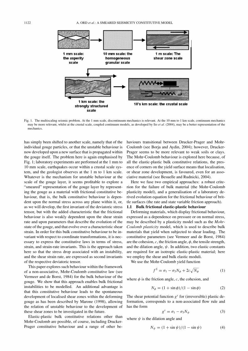
Fig. 1. The multiscaling seismic problem. At the 1 mm scale, discontinuum mechanics is relevant. At the 10 mm to 1 km scale, continuum mechanicsmay be more relevant, whilst at the crustal scale, coupled continuum models, as developed by Iio et al. (2004), may be a better representation of themechanics.
has simply been shifted to another scale, namely that of theindividual gouge particles, or that the unstable behaviour isnow developed upon a new surface that is propagated withinthe gouge itself. The problem here is again emphasised byFig. 1; laboratory experiments are performed at the 1 mm to10 mm scale, earthquakes occur within a crustal scale sys-tem, and the geologist observes at the 1 m to 1 km scale.Whatever is the mechanism for unstable behaviour at thescale of the gouge layer, it seems profitable to explore a“smeared” representation of the gouge layer by represent-ing the gouge as a material with frictional constitutive be-haviour, that is, the bulk constitutive behaviour is depen-dent upon the normal stress across any plane within it, or,as we will develop, the first invariant of the deviatoric stresstensor, but with the added characteristic that the frictionalbehaviour is also weakly dependent upon the shear strainrate and upon parameters that describe the evolution of thestate of the gouge, and that evolve over a characteristic shearstrain. In order for this bulk constitutive behaviour to be in-variant with respect to coordinate transformations, it is nec-essary to express the constitutive laws in terms of stress,strain, and strain-rate invariants. This is the approach takenhere so that the stress drop associated with an instability,and the shear strain rate, are expressed as second invariantsof the respective deviatoric tensor.
This paper explores such behaviour within the frameworkof a non-associative, Mohr-Coulomb constitutive law (seeVermeer and de Borst, 1984) for the bulk behaviour of thegouge. We show that this approach enables bulk frictionalinstabilities to be modelled. An additional advantage isthat this constitutive behaviour leads to the spontaneousdevelopment of localised shear zones within the deforminggouge as has been described by Marone (1998), allowingthe relation of unstable behaviour to the development ofthese shear zones to be investigated in the future.
Elastic-plastic bulk constitutive relations other thanMohr-Coulomb are possible, of course, including Drucker-Prager constitutive behaviour and a range of other be-
haviours transitional between Drucker-Prager and Mohr-Coulomb (see Borja and Aydin, 2004); however, Drucker-Prager seems to be more relevant to weak soils or clays.The Mohr-Coulomb behaviour is explored here because, ofall the elastic-plastic bulk constitutive relations, the pres-ence of corners on the yield surface means that localisation,or shear zone development, is favoured, even for an asso-ciative material (see Besuelle and Rudnicki, 2004).
Here we fuse two empirical approaches: a robust crite-rion for the failure of bulk material (the Mohr-Coulombplasticity model), and a generalisation of a laboratory de-rived evolution equation for the frictional behaviour of brit-tle surfaces (the rate and state variable friction approach).1.1 Bulk frictional elastic-plastic behaviour
Deforming materials, which display frictional behaviour,expressed as a dependence on pressure or on normal stress,may be described by a plasticity model such as the Mohr-Coulomb plasticity model, which is used to describe bulkmaterials that yield when subjected to shear loading. Theconstitutive parameters (see Vermeer and de Borst, 1984)are the cohesion, c, the friction angle, φ, the tensile strength,and the dilation angle, ψ . In addition, two elastic constantsare required for an isotropic elastic-plastic material; herewe employ the shear and bulk elastic moduli.
We use the Mohr-Coulomb yield function
f S = σ1 − σ3 Nφ + 2c√
Nφ (1)
where φ is the friction angle, c, the cohesion, and
Nφ = (1 + sin φ)/(1 − sin φ) (2)
The shear potential function gs for (irreversible) plastic de-formation, corresponds to a non-associated flow rule andhas the form
gs = σ1 − σ3 Nψ (3)
where ψ is the dilation angle and
Nψ = (1 + sin ψ)/(1 − sin ψ) (4)

A. ORD et al.: A SMEARED SEISMICITY CONSTITUTIVE MODEL 1123
Throughout we consider only plane strain, and take theprincipal stresses in the plane of deformation to be σ1 andσ3 with |σ1| > |σ3| and compression negative.
Shear dilatancy, or dilatancy, is the change in volumethat occurs with shear distortion of a material. In a Mohr-Coulomb material, for (irreversible) plastic deformation, di-latancy is characterized by a dilation angle, ψ , which is re-lated to the ratio of plastic volume change to plastic shearstrain. This angle can be specified in the Mohr-Coulombplasticity model (see Vermeer and de Borst, 1984) and isfound from a plot of volumetric strain versus axial straindetermined for triaxial tests or shear box tests. The initialslope for this plot corresponds to the elastic regime, whilethe slope used to measure the dilation angle correspondsto the plastic regime (see Ord, 1991, for examples of thederivation of this and other Mohr-Coulomb constitutive pa-rameters for sandstone and marble).
These are the criteria which describe the conditions forfailure, or yield, of an elastic-plastic Mohr-Coulomb mate-rial. Until the critical yield stress is reached, the material iselastic, and any deformation is reversible. On yield, the ma-terial may undergo irreversible or plastic deformation, andthe material behaviour during such plastic deformation isdescribed by the plastic potential gs or the flow rule whichdefines the orientation of the incremental plastic strain-ratevector for an imposed stress state. This incremental strainrate vector is always normal to the potential surface definedby Eq. (3). If this vector is also normal to the yield surfacedefined by Eq. (1), (i.e. φ = ψ), then the constitutive be-haviour is associative; otherwise it is non-associative. In themodels explored here, the shear flow rule is non-associatedand the tensile flow rule is associated.
Bifurcation, or a departure from homogeneous to inho-mogeneous behaviour, is allowed in such a plasticity modelso long as the dilation angle does not equal the friction an-gle; such material is called non-associative. Non-associatedMohr-Coulomb materials can therefore localise at yield (i.e.families of discontinuities such as shear bands develop in amaterial that starts as a homogeneous continuum). How-ever, as implied above, Mohr-Coulomb materials can alsolocalize when the stress state corresponds to a corner onthe yield surface (see Besuelle and Rudnicki, 2004). Thiscorresponds to stress states such as exist in axisymmetriccompression or extension.
In this paper we generalise the rate and state approach tofrictional sliding of a single block to apply to deformationof cataclastic fault gouge by writing the evolution equationsin terms of the second invariants of the stress and strain ratetensors within the framework of an elastic-plastic Mohr-Coulomb material. As such, the frictional response of thebulk gouge depends upon the pressure within the materialrather than the normal stress across a single sliding surface.This is expressed as a conical yield surface in stress spacewith a hexagonal cross section that expands in stress spacein the direction of the hydrostatic stress axis. The openingangle of this cone is related to the angle of friction of thematerial. Excellent discussions of this concept are givenby Borja and Aydin (2004), and by Besuelle and Rudnicki(2004). The conventional expression of the Mohr-Coulombrelationship is τ = c +µσN where τ is the shear stress on a
plane with normal stress σN , c is the cohesion and µ is thecoefficient of friction equal to tan φ where φ is the angle offriction. A way of writing this expression as a yield criterionis f = τ − c + µσN . Then, if f = 0 the material is at yieldand if f < 0 then the material is elastic. Equation (1) is theidentical expression for f written in terms of the principalstresses rather than in terms of τ and σN .
An additional intrinsic part of the formulation of theseconstitutive properties is the existence of another conicalsurface, namely, the potential surface, now existing in strainrate space. This also is hexagonal in cross section for aMohr-Coulomb material but the opening angle of this coneis related to the angle of dilation. The importance of thepotential surface is that the incremental strain rate vectoris normal to this surface and not the yield surface. Thusthe potential surface defines the deformation of the materialwhereas the yield surface defines the stress state. The po-tential surface defines the flow rule for the material whereasthe yield surface defines whether the material is at yield orelastic for a prescribed stress state. These concepts as wellas the theory are discussed by Vermeer and de Borst, 1984.Whereas the sliding direction of a single interface betweentwo pieces of rock is defined by the geometry of the sys-tem plus the imposed forces, the bulk deformation of anelastic-plastic material requires the definition of both theyield surface and the potential surface together with the im-posed stress or velocity field.
As we have indicated, Eqs. (3) and (4) define the potentialsurface in shear strain rate space, and hence in turn definethe increment of plastic shear strain once the stress state isdefined by Eqs. (1) and (2). This is equivalent to solving thepartial differential equations known as the flow rule.
Briefly, the flow rule is expressed as:
�εpi = γ ε∂gs
i /∂σi i = 1, 3 (5)
where �εpi are the principal incremental plastic strains,
gs is the potential function given in Eq. (3), and σi arethe principal stresses. The constant λs is obtained in eachincrement of deformation by requiring that the new stressat the end of the increment be located on the yield surfacegiven in Eq. (1).
After considerable manipulation, one obtains:
λs = f s(σ I1 , σ I
3 )/{(α1 − α2 Nψ) − (α2 − α1 Nφ)Nφ
}(6)
The superscript I refers to a new stress obtained by addingan increment of elastic stress to the old stress that existedat the beginning of the increment given the requirementthat the new stress state lies on the yield surface. α1 andα2 are functions of both the elastic shear and bulk moduliand Nϕ , Nψ are as given in Eqs. (2) and (4). Thus theimplementation of the flow rule requires the use of Eqs. (1),(2), (3) and (4). This explanation is quite condensed. Formore insight one should examine Vermeer and de Borstor better, the FLAC user’s manual (ITASCA, 2002; andsee Appendix A) to get a true appreciation of the processinvolved. Similar discussions can be found in the textbookby Malvern (1969) but in this case, the theory is appliedonly to associated plastic materials where the yield andpotential surfaces are coincident.

1124 A. ORD et al.: A SMEARED SEISMICITY CONSTITUTIVE MODEL
b ln(V/V0)
(b-a) ln(V/V0)
1 µm/s 10 µm/s
a ln(V/V0)
b ln(D/D0)
(b-a) ln(D/D0)
10-7s-1
a ln(D/D0)
Shear Strain /γc
10-8s-1
Sliding Distance / Dc
µ
µ
(a)
(b)
Fig. 2. a) Representation of the behaviour of the friction coefficient for velocity weakening behaviour (from Marone, 1998). b) Representation of thebehaviour of the friction coefficient for shear strain weakening behaviour, as developed in this paper.
1.2 Rate and state dependent frictional behaviourExperimental studies on frictional sliding between two
surfaces as performed and interpreted by Dieterich (1978,1979) and by Ruina (1980, 1983) have led to a constitutiverelation which describes shear stress τ at constant normalstress σN to be dependent on the relative slip velocity Vand the prior slip history in the form of dependence on aset of phenomenological parameters called state variables(θi ). The state variables describe the state of the slidingsurface and they evolve, as the surface slides, with a set ofcharacteristic lengths Dci .
The general forms of these relations as given by Ruinaare:
τ = F(V, σN , θ1, θ2, . . . θm) (7)
dθi
dt= Gi (V, σN , θ1, θ2, ....θm) i = 1, m (8)
During slip at a fixed slip rate and normal stress, the statevariables evolve toward steady-state values θ ss
i such that theshear stress evolves towards a steady-state value of τ ss(V )
corresponding to the imposed fixed speed and normal stress.The evolution of the coefficient of friction following a per-turbation in the sliding velocity is shown in Fig. 2(a); herethe behaviour is that of velocity weakening so that an in-crease in sliding velocity leads ultimately to a decrease inthe friction coefficient.
However, although such rate and state behaviour is com-monly attributed to frictional evolution between two slidingsurfaces, identical behaviour is also observed when a layerof gouge is intentionally placed between two sliding blocks
(see Marone, 1998, for a discussion). Thus, in extendingthe relations given in Eqs. (7) and (8) to the situation wheresignificant thicknesses of gouge are present, it seems prof-itable to explore the results of generalising these equationsso that the frictional evolution is expressed in terms of con-tinuum parameters such as strain rate and strain rather thanthe discontinuum parameters, V and Dc.
Equations (7) and (8) can be thought of as a discontinuumformulation of the evolution of friction as two blocks movewith a relative velocity, V , parallel to the interface betweenthem. The generalisation of such equations to develop aframe invariant constitutive relation that describes the evo-lution of friction in a continuum means that the evolutionneeds to be formulated in terms of invariants of the strainand strain-rate tensors. Moreover, since the deformationalresponse is strongly non-linear, the incremental forms of theconstitutive relations are relevant. Thus, instead of the char-acteristic distance, Dc, which is used in the discontinuumdescription to describe the spatial scale for frictional evo-lution (see Fig. 2(a)), we use a characteristic shear strain,γc.
Similarly, instead of the velocity, V , we use the maxi-mum shear strain-rate, D, which is the square root of thesecond invariant of the incremental strain rate deviator ten-sor. We can then write:
τ = F(D, σN , θ1, θ2, ....θm) (9)
dθi
dt= Gi (D, σN , θ1, θ2, . . . θm) i = 1, m (10)

A. ORD et al.: A SMEARED SEISMICITY CONSTITUTIVE MODEL 1125
Fig. 3. a) Undeformed state of numerical grid. b) Deformed numericalgrid. c) Contours of shear stress. Note that the conjugate set of shearbands is developed locally. Localities of histories shown in Fig. 4 areplotted as X, Y, and Z.
In Eqs. (9) and (10), σN should now be thought of as the firstinvariant of the deviatoric stress tensor, (σ11 +σ22 +σ33)/3.
In this paper we explore the effect of applying this kindof frictional behaviour to the evolution of the friction anglein the Mohr-Coulomb constitutive relation during a seismicevent. The implication here is that the variables θi are statevariables of the gouge, and that these evolve over a char-acteristic shear strain as the gouge deforms, with a depen-dence on the local shear strain rate, as shown in Fig. 2(b),now replacing Fig. 2(a). Throughout this paper from nowon, we refer to the square root of the second invariant of thedeviatoric stress tensor as the shear stress and the squareroot of the second invariant of the incremental deviatoricstrain rate tensor as the shear strain rate.
The rate and state dependant behaviour is formulated inthis instance as a single state variable law (i.e. m = 1 inEqs. (9) and (10)):
µ = µO + a ln(D/DO) + b(ξ) (11)
wheredξ/dt = −(ξ + ln(D/DO)D/γc. (12)
µ is the current friction coefficient, µO a reference frictioncoefficient, D the maximum shear strain rate at a pointin the continuum where µ is measured, DO a referencematerial maximum shear strain rate where µ0 is measured,a and b are constitutive variables, ξ is the state variable, andγc is a characteristic shear strain scaling the evolution of thestate variable.
Table 1. Mechanical properties for the simple shearing model.
Mechanical Property
bulk modulus 47.0 GPa
shear modulus 28.0 GPa
density 2700 kg.m−3
friction angle 30.0 degrees
dilation angle 1.0 degrees
cohesion 20.0 MPa
tensile strength 2.0 MPa
Table 2. Values for parameters in Eqs. (11), (12) and (13).
Parameter
reference maximum shearstrain rate Do 1 × 10⁻³ s−1
characteristic shear strain γc 2 × 10⁻²
b 0.008
a 0.006
a − b −0.002
steady state friction, µO , at 25 degreesreference maximum shear strain rate
In order now to apply this constitutive framework toa bulk material rather than a discrete sliding surface, weassume that φ, the friction angle included in the Mohr-Coulomb plasticity model, may be replaced by arctan µ,where µ is the friction coefficient involved in the rate andstate variable behaviour. The explicit behaviour of a singlesliding surface is in this way replaced by a smeared bulkdescription of the bulk material. This represents a multi-scaling from a distinct element description to a continuumdescription of the same problem on a larger scale. The ap-proach is similar to that of Lyakhovsky (2001; Lyakhovskyet al., 2001) who treat the incorporation of damage mechan-ics into a continuum code. In the formulation used here, thestate variable ξ is updated in each time step according to
ξnew = ξold − (ξold + ln(D/Do))(D/γc)�t (13)
where �t is the time step, which is calculated while the ex-periment is stepping numerically. The resulting friction co-efficient, updated through Eq. (11), is then returned to thebulk Mohr-Coulomb constitutive behaviour through updat-ing the friction angle.
In summary, our approach is to consider a non-associatedMohr-Coulomb material as our primary material. Thisis modified by specifying that the friction in the Mohr-Coulomb constitutive model evolves with shear strain in amanner analogous to rate and state dependent friction laws.The dilation angle is also included in such a constitutive for-mulation but we let it remain constant. Although there havebeen suggestions (particularly by Marone, 1998) that evolu-tion of dilatancy may be important for real fault behaviourwe have not explored evolution of dilatancy in this papersince it would add even greater complexity.

1126 A. ORD et al.: A SMEARED SEISMICITY CONSTITUTIVE MODEL
Time seconds
19.50
20.00
20.50
21.00
21.50
22.00
170.845 170.850 170.855 170.860 170.865 170.870 170.875
Fric
tion
angl
ede
gree
s
(a)
3.60E+08
3.62E+08
3.64E+08
3.66E+08
3.68E+08
170.845 170.850 170.855 170.860 170.865 170.870 170.875
Time seconds
Shea
r st
ress
Pa
(f)
Time seconds
19.50
20.00
20.50
21.00
21.50
22.00
22.50
170.845 170.850 170.855 170.860 170.865 170.870 170.875
Time seconds
Fric
tion
angl
ede
gree
s
(b)
5.00E-14
1.00E-13
1.50E-13
170.845 170.850 170.855 170.860 170.865 170.870 170.875
Shea
r st
rain
ra
te s
-1
Time seconds
(g)
20.00
20.50
21.00
21.50
22.00
170.845 170.850 170.855 170.860 170.865 170.870 170.875
Fric
tion
angl
ede
gree
s
Time seconds
(c)
Time seconds
Shea
r st
rain
ra
te s
-1
1.00E-13
2.00E-13
3.00E-13
4.00E-13
170.845 170.850 170.855 170.860 170.865 170.870 170.875
(h)
Shea
r st
ress
Pa
3.84E+08
3.86E+08
3.88E+08
3.90E+08
3.92E+08
3.94E+08
170.845 170.850 170.855 170.860 170.865 170.870 170.875
Time seconds
(d)
Time seconds
Shea
r st
rain
ra
te s
-1
5.00E-14
1.00E-13
1.50E-13
2.00E-13
170.845 170.850 170.855 170.860 170.865 170.870 170.875
(i)
Shea
r st
ress
Pa
4.00E+08
4.02E+08
4.04E+08
4.06E+08
4.08E+08
4.10E+08
4.12E+08
170.845 170.850 170.855 170.860 170.865 170.870 170.875
Time seconds
(e)
Fig. 4. Behaviour over 0.3 seconds for the three zones shown in Fig. 3(c), in the simple shearing model. (a), (b), (c): Friction angle versus time. (d),(e), (f): Shear stress versus time. (g), (h), (i): Shear strain rate versus time. (a), (d), (g): Position X in Fig. 3(c). (b), (e), (h): Position Y in Fig. 3(c).(c), (f), (i): Position Z in Fig. 3(c).

A. ORD et al.: A SMEARED SEISMICITY CONSTITUTIVE MODEL 1127
2. A Small Scale Model2.1 Geological description
The development of structure in the form of shear bandswithin the deforming gouge of the fault zone is documentedby various authors (see Marone, 1998, for a review). Suchlocalisation introduces another spatial scale, other than γc,into the structural evolution of the material. The smearedapproach adopted in this paper now allows us to investigatethe evolution of instabilities during the development of suchstructures, building on earlier work exploring the initiationand development of shear zones and their patterning withinan elastic-plastic (Mohr-Coulomb) material (Ord, 1991).One should note here that shear bands form spontaneouslyat yield in non-associative elastic-plastic materials or inelastic-plastic materials with corners on the yield surface(see Besuelle and Rudnicki, 2004, for a discussion). Thespacing of the shear bands here depends on the grid sizeused since there is no internal length scale incorporatedwithin the Mohr-Coulomb constitutive law.2.2 Computational model
This square model, 75 metres on edge (75×75 compu-tational zones), is shown in plan view in the undeformedstate in Fig. 3(a); gravity is not turned on. The mechanicalproperties of the model are as in Table 1.
Velocity boundary conditions are imposed which resultin isochoric bulk simple shearing. Rate and state variabledependant behaviour is imposed, with properties as in Ta-ble 2.
As described above, the classical rate and state formu-lation is specifically for a sliding surface, for unstable be-haviour along a discontinuity. We choose here that this re-mains a critical behaviour at grain scale, and we scale upto a continuum formulation for a shear zone by assumingthat the arc tan of the friction coefficient µ, may be used asthe friction angle φ in the Mohr-Coulomb plasticity model.Variations in the magnitude of Dc, as determined by theoryand by laboratory and field observations, are discussed byMarone (1998). In this study, we have explored a range ofvalues for γc from 2 × 10⁻² to 2 × 10², and provide resultsfor γc of 2 × 10−2.2.3 Results from the small scale model
Zones of localised deformation develop in the model,represented as planar distortions in the otherwise squaregrid (Fig. 3(b)) and also as zones roughly parallel to theshearing direction of alternating high and low shear stress(Fig. 3(c)). Histories were tracked of friction angle, thesecond invariant of the deviatoric stress tensor (the shearstress), and the second invariant of the deviatoric strain ratetensor (the strain rate) for three zones shown in Fig. 3(c)from different positions in the model. The resulting be-haviours, patterns and magnitudes, were similar for thethree zones (demonstrating the ‘well behaved continuumbehaviour’ referred to in Appendix C, with deformation oc-curring in a coherent manner across adjacent zones). Fig-ure 4 shows the behaviour of these 3 variables over 20000numerical steps, within a total run of 3.1 million steps,equivalent to a model time of about 170 seconds. This takesabout 45 hours running a Pentium 4 chip with a CPU of 3.20GHz. Figure 5 shows the detailed behaviour of these 3 vari-ables from a slightly later part of this time series, over just
19.80
20.00
20.20
20.40
20.60
20.80
21.00
21.20
21.40
21.60
Time seconds
Time seconds
Time seconds
170.86390
5.0000E-03
1.0000E-02
1.5000E-02
2.0000E-02
2.5000E-02
E+084.00
4.02E+08
4.04E+08
4.06E+08
4.08E+08
4.10E+08
4.12E+08
Shea
r st
rain
ra
te s
-1
Shea
r sr
ess
Pa
Fr
icti
on a
ngle
de
gree
s
(c)
(b)
(a)
170.86390
170.86390
170.86391
170.86391
170.86391
Fig. 5. Detailed behaviour over about 1.0e-5 seconds for zone Y in thesimple shearing model shown in Fig. 3(c). a) Shear strain rate versustime. b) Shear stress versus time. c) Friction angle versus time.
1.0 × 10⁻⁵ seconds. There is a shear stress increase (ap-proximately 1 MPa; Fig. 5(b)) accompanying the increasein shear strain rate following the stick-slip event (Fig. 5(a)),but instability in the system rapidly overtakes the stress evo-lution and drives it into a rapid stress drop of approximately10 MPa. The friction angle (Fig. 5(c)) continues to evolvewithin this constrained system.
The stick-slip behaviour exhibited by these results pro-vides a degree of validation as to the inclusion of rate andstate dependant variable behaviour within a continuum for-mulation for an elastic-plastic material with cohesion.
Clearly, there is slightly different behaviour in each ofthe three zones shown in Fig. 3(c). Although these threezones occupy slightly different positions relative to theshear zones, it is not clear whether the different behavioursare related to these different deformation environments. Toascertain this, a much finer resolution model is needed, andthis will be the subject of future work.
3. A Large Scale Model3.1 Geological description
The particular model described here was developed inparallel with that described by Hobbs et al. (2004, this vol-ume), and reflects interpretations of the Nagamichi-Rifuseismogenic fault in the Sendai region of NE Japan (Sato etal., 2002). Discussions at the Sendai conference, the first ofthis series, focussed on processes operating at some depthcorresponding to the base of the seismogenic zone (Ito et

1128 A. ORD et al.: A SMEARED SEISMICITY CONSTITUTIVE MODEL
100 km
b
a
30 km
3 2
1
Fig. 6. a) Undeformed mesh for the crustal model. b) Position of region (dark grey) for which the rate and state dependant variable behaviour is applied.The markers, , represent regions for which histories of variables are stored throughout the numerical experiments.
Table 3. Mechanical properties of the large scale crustal model.
Mechanical Property
bulk modulus 4.7 GPa
shear modulus 2.8 GPa
density 2700 kg.m−3
friction angle 30.0 degrees
initial friction angle within fault 25.0 degrees
dilation angle 1.0 degrees
cohesion 20.0 MPa
tensile strength 2.0 MPa
al., 2002), including the classical mechanism involving in-stability of frictional sliding in the brittle regime (Byerleefriction) for the production of large earthquakes at this depth(Hobbs et al., 2002). This section extends these discus-sions through exploration of the application of rate and statedependant variable behaviour combined with elastic-plasticbulk material behaviour to the development and evolutionof instabilities within a crustal-scale fault.3.2 Computational model
As a first step, we choose a model 100 km long and 30km deep for simulation of the Earth’s crust (see Fig. 6(a) forcomputational grid). We assume at this stage that the ma-terial behaviour is temperature independent and has elastic-plastic rheology only. No fluids are present. The mechan-ical properties are assumed to be homogeneous, as a firststep towards understanding the system, and are providedin Table 3. A shear zone is incorporated a priori into themodel; it dips at 45 degrees from the ground surface downto 15 km depth and is 1.4 km thick. The fault has the samemechanical properties as the surrounding material exceptfor the friction angle, which is initially 25 degrees; this
means the fault has a lower yield stress than the surround-ing material. The friction angle of each zone within the faultchanges continuously throughout the model with the appli-cation of the rate and state dependant variable behaviourshown in Table 2.
Gravity is applied to the model. The lower horizontalsurface is a roller boundary in the x direction, and the twovertical surfaces are roller boundaries in the z direction. Thetop surface is left free. A bulk horizontal shortening rate ofabout 2 × 10⁻¹⁵s−1 is imposed through applying an hori-zontal velocity to each of the vertical boundaries. A litho-static stress regime is initialised throughout the model, andthe model is brought to a steady state under these bound-ary conditions (200,000 numerical steps). Similar dampingconditions to the small scale shearing model were also im-posed, and are considered in Appendix B.
The rate and state formulation used is the same as in thesimple shearing model, with the same values for parametersas in Table 2. As a first exploration of the behaviour ofthe fault, this formulation was applied only to the dippingregion described earlier, and only from 2.4 km beneaththe ground surface down to 15 km depth. The frictionangle for the material within this region was updated everystep according to the above-described bulk rate and statedependant formulation.3.3 Results for the crustal scale model
The following results are examples of the solution thatwe obtain with the specific boundary conditions and pa-rameters that we have chosen for our analysis. Our goalfor this contribution was to formulate a numerically sounddescription of a hybrid continuum-rate and state variablefriction approach. We have not done an extensive param-eter search for comparison with natural scenarios. This isclearly the next step after the initial successful formulationof the model. The following results therefore should not becompared one-on-one with nature. We feel that a careful

A. ORD et al.: A SMEARED SEISMICITY CONSTITUTIVE MODEL 1129
15.00
20.00
25.00
30.00
30000.00 30500.00 31000.00 31500.00 32000.00 32500.00 33000.00
Fric
tion
ang
le
degr
ees
Time seconds
(a)
Time seconds
1.21E+08
1.22E+08
1.23E+08
1.24E+08
1.25E+08
1.26E+08
30000.00 30500.00 31000.00 31500.00 32000.00 32500.00 33000.00
Shea
r st
ress
Pa
(f)Fr
icti
on a
ngle
de
gree
s
15.00
20.00
25.00
30.00
30000.00 30500.00 3100 2000.00 32500.00 33000.000.00 31500.00 3
Time seconds
(b)
5.00E-07
1.00E-06
1.50E-06
30000.00 30500.00 31000.00 31500.00 32000.00 32500.00 33000.00Sh
ear
stra
in
ra
-1
Time seconds te
s
(g)
15.00
20.00
25.00
30.00
30000.00 30500.00 31000.00 .00 32500.00 33000.0031500.00 32000
Time seconds
Fric
tion
angl
e de
gree
s
(c)
5.00E-07
1.00E-06
1.50E-06
30000.00 30500.00 31000.00 31500.00 32000.00 32500.00 33000.00
Shea
r st
rain
ra
-1
te
s
Time seconds
(h)
6.00E+07
6.05E+07
6.10E+07
6.15E+07
6.20E+07
6.25E+07
30000.00 30500.00 31000.00 31500.00 32000.00 32500.00 33000.00
Time seconds
Shea
r st
ress
Pa
(d)
Time seconds
5.00E-07
1.00E-06
1.50E-06
30000.00 30500.00 31000.00 31500.00 32000.00 32500.00 33000.00
Shea
r st
rain
ra
s-1
te
(i)
8.80E+07
8.90E+07
9.00E+07
9.10E+07
9.20E+07
9.30E+07
9.40E+07
30000.00 30500.00 31000.00 31500.00 32000.00 32500.00 33000.00
Shea
r st
ress
Pa
Time seconds
(e)
Log
(Sh
ear
stra
in r
ate
s-1
)
Time seconds
-20.00
-15.00
-10.00
-5.00
30000.00 30500.00 31000.00 31500.00 32000.00 32500.00 33000.00
(j)
Fig. 7. Behaviour over 2500 seconds for the three zones shown in Fig. 6(b), in the crustal model. (a), (b), (c): Friction angle versus time. (d), (e), (f):Shear stress versus time. (g), (h), (i): Shear strain rate versus time. (a), (d), (g): Position 3 in Fig. 6(b). (b), (e), (h): Position 2 in Fig. 6(b). (c), (f),(i): Position 1 in Fig. 6(b). Figure 7(j) is a re-plot of Fig. 7(i), but now the logarithm of the shear strain rate is plotted against time. Notice the strongresemblance to Fig. 7(c).

1130 A. ORD et al.: A SMEARED SEISMICITY CONSTITUTIVE MODEL
Fric
tion
ang
le
degr
ees
Shea
r st
ress
Pa
4.00E-06
6.00E-06
8.00E-06
1.00E-05
30400.00 30500.00 30600.00 30700.00 30800.00 30900.00
Shea
r st
rain
ra
-1
te s
2.00E-06
8.90E+07
9.00E+07
9.10E+07
9.20E+07
9.30E+07
9.40E+07
30400.00 30500.00 30600.00 30700.00 30800.00 30900.00
15.00
20.00
25.00
30.00
30400.00 30500.00 30600.00 30700.00 30800.00 30900.00
Time seconds
Time seconds
Time seconds
(c)
(b)
(a)
Fig. 8. Detailed behaviour over about 500 seconds for the first event inFig. 7(h) for zone 2 in the crustal model shown in Fig. 6(b). a) Shearstrain rate versus time. b) Shear stress versus time. c) Friction angleversus time.
discussion of the basic features of our smeared continuummethod is warranted first.
Histories were collected continuously of the friction an-gle, shear stress, and strain rate for 3 zones at differentdepths within the fault region, originally at positions 6.3km (point 3), 10.3 km (point 2), and 14.2 km (point 1) be-neath the surface, as shown in Fig. 6(b). We show here justthree unstable events (Fig. 7), occurring in a continuing nu-merical run. The zonal stick-slip behaviour described aboveoccurs within these events, and is described in detail for thefirst event occurring at 10.3 km, in Fig. 8.
A zone situated near the middle of the fault (point 2at 10.3 km in Fig. 6(b)) demonstrates behaviours similarto those described above for the simple shearing model:Stick-slip in the shear strain rate (Fig. 8(a)) is accompa-nied by a stress drop of 3.5 MPa (from 93.5 to 90.2 MPa;Fig. 8(b)) and an instantaneous increase in the friction angle(Fig. 8(c)), followed by a gentle decrease. In this case, therapid rise and fall of the strain rate (Fig. 8(a)) is followedby a less abrupt increase and decrease also in the strain rate.The stress drop occurs over only 0.05 seconds (Fig. 8(b)).
Figure 7 shows that this behaviour of the strain rate at 10.3km depth (Fig. 7(b)) appears to be reflected by zones bothlower, at 14.2 km (Fig. 7(c); point 1, Fig. 6(b)), and higherin the crust, at 6.3 km (Fig. 7(a); point 3, Fig. 6(b)). It ap-pears that instability is nucleated simultaneously at all threepoints in the fault.
4. DiscussionWe have shown in this paper that the incorporation of a
“smeared” rate and state formulation of friction evolutioninto otherwise bulk Mohr-Coulomb elastic plastic constitu-tive behaviour is capable of generating unstable behaviourwithin deforming fault gouge. This behaviour is identical tothat demonstrated in other applications of rate and state de-pendant constitutive behaviour to discrete sliding surfaces(e.g. Tse and Rice, 1986; Lorig and Hobbs, 1990) in that anunstable event is accompanied by a stress drop, frictionalevolution, and stick-slip behaviour. As indicated above, thisapproach is equivalent to the introduction of smeared dam-age mechanics into continuum codes (Lyakhovsky, 2001;Lyakhovsky et al., 2001). Again, as with other numericalstudies of unstable sliding of discrete surfaces the recur-rence time between unstable events seems to be controlledby the elasticity of the system, as discussed by Rice (1983),Rice and Tse (1986), and by Tse and Rice (1986), and isdramatically short in comparison to recurrence times on nat-ural faults. Various attempts have been made to address thisproblem with possible solutions including thermal pressur-ization (Sibson, 1973; see Noda and Shimamoto, 2004, for areview) and various aspects of melt generation (see Hiroseand Shimamoto, 2004, for a review) with various degreesof success. An interesting alternative to the introductionof increasingly complex mechanisms has been explored byIio (2004, this volume) in the form of feedback couplingbetween far-field sliding on a subduction zone through aviscous lower crust. This approach replaces the crust witha system of elastic springs, frictional sliders and dashpots(Fig. 1) and provides the opportunity for strong instanta-neous (elastic) and long-term (viscous) feedback interac-tions between various parts of the crust. These types of cou-pled mechanical systems are more realistic representationsof the crust than simple spring slider systems; they showconsiderable promise and are the subject of future work.
Experimental work by Shimamoto (1986), and Chesterand Higgs (1992) has shown that even for a material thatexhibits velocity weakening at a velocity v = v1, that mate-rial may evolve at velocities greater than v1 to exhibit veloc-ity strengthening behaviour. This evolution in frictional be-haviour is particularly appealing because it supplies a mech-anism of inhibiting unstable slip once it has been nucleatedat velocity v1. Such behaviour may also be important inenabling relatively long recurrence times between unstableevents and this issue should also be the subject of futurework.
5. ConclusionsModelling the behaviour from continuum to discrete de-
formation and from quasistatic to fully dynamic behaviouris one of the great challenges in the Geosciences. Severalapproaches have been proposed but none has been able fully

A. ORD et al.: A SMEARED SEISMICITY CONSTITUTIVE MODEL 1131
to reproduce the patterns observed in nature. This contri-bution provides some encouraging results for future anal-yses, particularly in investigation and comparison of twoend-member approaches: one in which the best empiricaldata are combined to reproduce the basic phenomenon ofearthquakes (this paper belongs to this class) and the otherwhere earthquakes are simulated by an ‘ab initio’ approachavoiding, if possible, any empirical description. A novelcomputational method for understanding the mechanismsof earthquakes should be devised as a result of comparisonof these two end members.
In this approach rate and state variable behaviour hasbeen incorporated into a bulk constitutive model and ap-plied to prediction of unstable behaviour in a homogeneouscrustal model. Since in the second model described here,all 30 km thickness of crust was assumed to be representedby an elastic-plastic Mohr-Coulomb behaviour; there wasno possible feedback between an upper elastic-plastic crust,and a lower viscous crust. It is suggested that such couplingand feedback is a requirement before geologically realis-tic recurrence times for instabilities may be attained, andbefore physically realistic energies are involved during theco-seismic slip periods. Future work based on this approachshould include coupling with fluid flow, and exploration ofthe behaviour of fluid flow through the crust associated withfaulting and earthquakes, leading to improved understand-ing of the feedback between earthquakes, faulting, and fluidflow.
Acknowledgments. We thank the organisers of the Second Inter-national Symposium on Slip and Flow Process in and below theSeismogenic Region for their generosity in inviting all three of usto Japan to contribute to and partake in this stimulating and en-thusiastic meeting. It was also a great pleasure to experience thesafer aspects of living above a subduction zone such as bathingin natural hot springs. This contribution has greatly benefited asa result of the reviewers’ comments, and we greatly appreciateProfessor IIo’s support and patience for our continuing work onthe manuscript. We acknowledge the Predictive Mineral Discov-ery Cooperative Research Centre’s support of this research intogeological processes critical to our understanding of mineralisingsystems.
Appendix A. Numerical TechniqueModelling of frictional sliding between two surfaces has
been noted by Aagaard et al. (2001) to have been addressedin two distinct ways, through exploring the evolution ofstress on the fault, and through modelling the rupture be-haviour during earthquakes. Formulation of the rate- andstate-dependant models (see review by Marone, 1998) hasevolved through research on the former topic, while workon the latter topic has included either slip-weakening, ora combination of slip-weakening and rate-weakening be-haviour. Incorporation of rupture dynamics in simulationsof earthquakes and related processes has been explored indetail by many researchers including Tse and Rice (1986),Horowitz and Ruina (1989), Rice (1993), Cochard andMadariaga (1994), Ben-Zion and Rice (1995), Ben-Zion(1996), Cochard and Madariaga (1996), Rice and Ben-Zion(1996), Ben-Zion (2001), and Rice et al. (2001).
Advances in computer chip technology as well as in com-putational architectures and languages have allowed more
efficient and faster computational modelling. Aagaard etal. (2001) note the increase in researchers using finite ele-ment, finite difference, and boundary integral methods withwhich to explore dynamic rupturing, moving into three di-mensions.
Research has also addressed the incorporation of fric-tion laws into continuum approximations supposing steady-state. In this case, Amontons’ law is incorporated intothe continuum formulation, with allowance made for time-dependence of frictional strength through an arbitrarystrain-rate softening coefficient (Neumann and Zuber, 1995;Behn et al., 2002), using a Lagrangian visco-plastic finiteelement model.
In this paper, allowance is made for rate- and state-dependence of the frictional strength. An explicit, finitedifference program is used (Fast Lagrangian Analysis ofContinua, FLAC) to explore this non-linear, dynamic be-haviour. The numerical formulation is described in detailin the Users Handbook for FLAC (ITASCA, 2002). Insummary, the approach is conceptually similar to that ofdynamic relaxation (proposed by Otter et al., 1966), withadaptations for arbitrary grid shapes and large-strains; thefinite difference scheme follows the approach of Wilkins(1964). In the finite difference method (see for exampleDesai and Christian, 1977), every derivative in the set ofgoverning equations is replaced directly by an algebraic ex-pression written in terms of the field variables (e.g. stress ordisplacement) at discrete points in space; these variables areundefined within elements. The full dynamic equations ofmotion are included in the formulation with the aim of en-suring that the numerical scheme is stable when the physicalsystem being modelled is unstable. Inertial terms are in-cluded and kinetic energy is generated and dissipated, withthe influences of such energy generation and dissipation onthe solution fully taken into account.
The general calculation procedure (ITASCA, 2002) firstinvokes the equations of motion to derive new velocities anddisplacements from stresses and forces. Second, strain ratesare derived from velocities, and new stresses from strainrates. One timestep is taken for one full computationalcycle. A timestep is chosen which is sufficiently smallthat information cannot physically pass from one elementto another in that interval. Disturbances propagate acrossseveral elements only after several cycles. The aim is toensure that the calculational ‘wave speed’ always keepsahead of the physical wave speed. The stability conditionfor an elastic solid discretized into elements of size �x is
�t < �x/C
where C is the maximum speed at which information canpropagate, typically, the p-wave speed, C p, where
C p = ((K + 4G/3)/ρ)0.5 (see Jaeger, 1969).
Here K is the bulk elastic modulus, G is the shear elasticmodulus, and ρ is the density.
Given the parameters for both models described here,for the small scale model, the primary wave velocity isC p = 5589 m.s−1 and the shear wave velocity is Cs = 3220m.s−1; for the large scale model, the primary wave veloc-ity is C p = 1767 m.s−1 and the shear wave velocity is

1132 A. ORD et al.: A SMEARED SEISMICITY CONSTITUTIVE MODEL
Cs = 1018 m.s−1. This implies that for a typical time stepof 0.000125 seconds, as in the small scale model, the p-wave travels 0.7 metres and the s-wave travels 0.4 metres.Similarly, for a typical time step of 0.05 seconds, as in thelarge scale model, the p-wave travel 89 metres and the s-wave travels 51 metres. The element size is always 1 metrein the small scale model, and is always larger than 100 me-tres in the large scale model so that the above condition, thatmore than one step is always needed to propagate informa-tion across an element, is always satisfied.
The program performs a ‘Lagrangian’ analysis in that co-ordinates are updated at each timestep in large-strain mode;the incremental displacements are added to the coordinatesso that the grid moves and deforms with the material it rep-resents.
Appendix B. Dynamic DampingFor a dynamic analysis, the damping in the numeri-
cal simulation should reproduce in magnitude and formthe energy losses in the natural system when subjectedto a dynamic loading. What is normally attempted ina dynamic analysis is the reproduction of the frequency-independent damping of materials, particularly geologi-cal materials (Biggs, 1964; Cundall, 1976) at the correctlevel. However, in analyses that use a plasticity constitu-tive model such as Mohr-Coulomb, a considerable amountof energy dissipation can occur during plastic flow. Thus,for many dynamic analyses that involve large-strain, onlya minimal percentage of damping (e.g. 0.5%) may be re-quired. Further, dissipation will increase with amplitude forstress/strain cycles that involve plastic flow.
For dynamic calculations, a certain fraction of criticaldamping is usually required over a given frequency range.This type of damping is known as Rayleigh damping, wherethe fraction of critical damping operating at the centre fre-quency (in cycle/sec or Hertz) is input by the user. In thiscase, we used normal Rayleigh damping, and did not restrictthe model to stiffness or mass-proportional damping.
As part of the dynamic analysis, quiet boundaries (thatis, energy absorbing) were initially applied to the two verti-cal and lower horizontal boundaries. For reasons discussedbelow this approach was later abandoned. Numerical meth-ods relying on the discretization of a finite region of spacerequire that appropriate conditions be enforced at the artifi-cial numerical boundaries. In static analyses, fixed or elas-tic boundaries can be realistically placed at some distancefrom the region of interest. In dynamic problems, however,such boundary conditions cause the reflection of outwardpropagating waves back into the model and do not allowthe necessary energy radiation. The use of a larger modelcan minimize the problem, since material damping will ab-sorb most of the energy in the waves reflected from distantboundaries. However, this solution leads to a large com-putational burden. The alternative is to use quiet (or ab-sorbing) boundaries. The viscous boundary developed byLysmer and Kuhlemeyer (1969) is used in this case. It isbased on the use of independent dashpots in the normal andshear directions at the model boundaries (ITASCA, 2002).
The application of this approach proceeds by assumingfirst that the model has been brought to quasi-static equilib-
rium for the conditions of choice before the dynamic anal-ysis is begun. In the case of the larger, crustal model, weare shortening the model using constant velocity boundaryconditions on each vertical boundary. On initiation of thedynamic analysis, including application of the quiet bound-aries, the code calculates the reaction forces obtained at thetwo vertical boundaries, and then replaces the applied ve-locity boundary conditions with equal and opposite reactionforces for the duration of the dynamic analysis. However,at least for the purpose of the crustal models run here, ap-plying reaction forces instead of constant velocities at theboundaries leads to entirely the wrong result. The veloc-ity boundary conditions appear to provide a driving forcefor the ‘earthquake system’ that is not sustained with thereaction force boundary conditions. Instead, in the lattercase, as the model tends to equilibrium (remembering thatthe top surface is free to move), the forces in the modeldecrease and, as a consequence, in order to maintain the re-action forces at the boundary conditions, the code imposeshigher and higher velocities. At the same stage in a num-ber of models (∼ 6 × 10⁵ steps or ∼ 20 × 103 seconds),the variables which are being tracked by histories becomecompletely stable, and remain stable out past 107 steps or3 × 105 seconds. Quiet boundaries were therefore not ap-plied for any further experiments. This approach workedalso for the smaller, shearing model for which it was suf-ficient to initialize the velocity boundary conditions beforebeginning the dynamic analysis. We rely on material damp-ing and the larger model for absorption of reflected energy.
Appendix C. Mesh SensitivityRice (1993) was the first to focus on the dependence
of the results of numerical simulations on cell, or compu-tational grid, size, allowing for ‘inherently discrete’ faultmodels (fault models that have no well-defined continuumlimit). Ben-Zion (2001) summarises the resulting researchon the dependency of numerical results on the grid size,which occurs for simulations in which the assumed consti-tutive laws do not include a length scale over which ma-terial properties evolve, one example being the frictionallaw (Behn et al., 2002). Further (see Ben-Zion, 2001),it is suggested by Rice and Ben-Zion (1996) that earth-quake complexities observed from simulations with dis-crete and continuum systems (defined according to the suc-cess or otherwise of the coupling between the mathemati-cal structures and the numerical calculations) are generatedprimarily by strong fault heterogeneities rather than anytime-dependence of the system through quasi-static (Tseand Rice, 1986), quasi-dynamic (Rice, 1993; Ben-Zion andRice, 1995), or fully dynamic (Rice and Ben-Zion, 1996:‘we have found no evidence that inclusion of fully iner-tial elastodynamics brings small event complexity of G-R (Gutenberg-Richter) type to our smooth fault models’)simulations. Failure in a model may include the gradualand cooperative behaviour of many numerical cells (a well-behaved continuum behaviour); or failure may occur dis-continuously with slip so that numerical zones may fail in-dividually for any grid size (a poorly-behaved continuumbehaviour, ‘inherently discrete’).
The models represented here exhibit continuum be-

A. ORD et al.: A SMEARED SEISMICITY CONSTITUTIVE MODEL 1133
haviour, according to this description, in that many numeri-cal cells behave cooperatively, as shown in Figs. 4 and 7.
ReferencesAagaard, B. T., T. H. Heaton, and J. F. Hall, Dynamic earthquake ruptures
in the presence of lithostatic normal stresses: Implications for frictionmodels and heat production, Bulletin of the Seismological Society ofAmerica, 91, 1765–1796, 2001.
Amontons, G., Histoire de l’Academie Royale des Sciences avec les Mem-oires de Mathematique et de Physique, 203–222, 1699.
Behn, M. D., J. Lin, and M. T. Zuber, A continuum mechanics modelfor normal faulting using a strain-rate softening rheology: Implicationsfor thermal and rheological controls on continental and oceanic rifting,Earth and Planetary Science Letters, 202, 725–740, 2002.
Ben-Zion, Y., Stress, slip, and earthquakes in models of complex single-fault systems incorporating brittle and creep deformations, Journal ofGeophysical Research, 101, 5677–5706, 1996.
Ben-Zion, Y., Dynamic ruptures in recent models of earthquake faults,Journal of the Mechanics and Physics of Solids, 49, 2209–2244, 2001.
Ben-Zion, Y. and J. R. Rice, Slip patterns and earthquake populationsalong different classes of faults in elastic solids, Journal of GeophysicalResearch, 100, 12,959–12,983, 1995.
Besuelle, P. and J. W. Rudnicki, Localization: Shear Bands and Com-paction Bands. Mechanics of Fluid Saturated Rocks, edited by Y.Gueguen and M. Bouteca, International Geophysics Series, 89, ElsevierAcademic Press, Amsterdam, 446 pp., 2004.
Biggs, J. M., Introduction to Structural Dynamics, New York: McGraw-Hill, 1964.
Borja, R. I. and A. Aydin, Computational modeling of deformation bandsin granular media. I. Geological and mathematical framework, Com-puter Methods in Applied Mechanics and Engineering, 193, 2667–2698,2004.
Bowden, F. P. and D. Tabor, The Friction and Lubrication of Solids, Part I,Clarendon Press, Oxford, 1950.
Chester, F. M. and N. G. Higgs, Multimechanism friction constitutivemodel for ultrafine quartz gouge at hypocentral conditions, J. Geophys.Res., 97, 1859–1870, 1992.
Cochard, A. and R. Madariaga, Dynamic faulting under rate-dependentfriction, Pure and Applied Geophysics, 142, 419–445, 1994.
Cochard, A. and R. Madariaga, Complexity of seismicity due to highlyrate-dependent friction, Journal of Geophysical Research, 101, 25,321–25,336, 1996.
Cundall, P. A., Explicit finite difference methods in geomechanics, inNumerical Methods in Engineering, 1, 132–150, 1976.
Desai, C. S. and J. T. Christian, Numerical Methods in Geomechanics,McGraw-Hill, New York, 783 pp., 1977.
Dieterich, J. H., Time-dependent friction and the mechanics of stick slip,Pageoph, 116, 790–806, 1978.
Dieterich, J. H., Modelling of rock friction. Experimental results and con-stitutive equations, J. Geophys. Res., 84, 2161–2168, 1979.
Estrin, Y. and Y. Brechet, On a model of frictional sliding, Pure andApplied Geophysics, 147, 745–762, 1996.
Gu, J.-C., J. R. Rice, A. L. Ruina, and S. T. Tse, Slip motion and stability ofa single degree of freedom elastic system with rate and state dependentfriction, J. Mech. Phys. Solids, 32, 167–196, 1984.
Hirose, T. and T. Shimamoto, Growth of molten zone as a mechanism ofslip weakening of simulated faults in gabbro during frictional melting,J. Geophys. Res., 2004 (accepted).
Hobbs, B. E., H. Tanaka, and Y. Iio, Acceleration of slip motion in deepextensions of seismogenic faults in and below the seismogenic region,Earth Planets Space, 54, 1195–1205, 2002.
Hobbs, B. E., A. Ord, K. Regenauer-Lieb, and B. Drummond, Fluid reser-voirs in the crust and mechanical coupling between the upper and lowercrust, Earth Planets Space, 56, this issue, 1151–1161, 2004.
Horowitz, F. G. and A. Ruina, Slip patterns in a spatially homogeneousfault model, J. Geophys. Res., 94, 10279–10298, 1989.
Iio, Y., T. Sagiya, and Y. Kobayashi. What controls the occurrence ofshallow intraplate earthquakes?, Earth Planets Space, 56, this issue,1077–1086, 2004.
ITASCA, FLAC, Fast Lagrangian Analysis of Continua, User’s Guide,Version 4.00. ITASCA, Minnesota, USA, 2002.
Ito, H., G. Beroza, K. Fujimoto, and Y. Ogawa, Preface, Earth Planets
Space, 54, 999–100, 2002.Jaeger, J. C., Elasticity, Fracture and Flow, Chapman and Hall, London,
268 pp., 3rd edition, 1969.Lavenda, B. H., Thermodynamics of Irreversible Processes, Macmillan
Press Ltd., London, 182 pp., 1978.Lorig, L. J. and B. E. Hobbs, Numerical modelling of slip instability using
the distinct element method with state variable friction laws, Int. J. RockMech. Min. Sci. and Geomech. Abstr., 27, 525–534, 1990.
Lyakhovsky, V., Scaling of fracture length and distributed damage, Geo-physical Journal International, 144, 114–122, 2001.
Lyakhovsky, V., Y. Ben-Zion, and A. Agnon, Earthquake cycles, faultzones, and seismicity patterns in a rheologically layered lithosphere,Journal of Geophysical Research, 106, 4103–4120, 2001.
Lysmer, J. and R. L. Kuhlemeyer, Finite dynamic model for infinite media,J. Eng. Mech., 95, 859–877, 1969.
MacCurdy, E. da Vinci, L. Notebooks. Translation into English, JonathanCape, London, 1938.
Malvern, L. E., Introduction to the Mechanics of a Continuous Medium,Prentice-Hall, Inc., New Jersey, 713 pp., 1969.
Marone, C., Laboratory-derived friction laws and their application to seis-mic faulting, Annu. Rev. Earth Planet. Sci., 26, 643–696, 1998.
Neumann, G. and M. Zuber, A continuum approach to the develomentof normal faults, in Proc. 35th US Symposium on Rock Mechanics,Lake Tahoe, Nevada, edited by J. Daemen and R. Schultz, pp. 191–198,Balkema, 1995.
Noda, H. and T. Shimamoto, Thermal pressurization and slip-weakeningdistance of a fault: An example of the Hanaore fault, Southwest Japan,Bull. Seism. Soc. Amer., 2004 (submitted).
Ord, A., Deformation of Rock: A pressure-sensitive, dilatant material, Pureand Applied Geophysics, 137, 337–366, 1991.
Otter, J. R. H., A. C. Cassell, and R. E. Hobbs, Dynamic Relaxation, PaperNo. 6986, Proc. Inst. Civil Eng., 35, 633–656, 1966.
Regenauer-Lieb, K. and D. Yuen, Positive feedback of interacting duc-tile faults from coupling of equation of state, rheology and thermal-mechanics, Physics of Earth and Planetary Interiors, 142, 113–135,2004.
Rice, J. R., Constitutive relations for fault slip and earthquake instabilities,Pure and Applied Geophysics, 121, 443–475, 1983.
Rice, J. R., Spatio-temporal complexity of slip on a fault, Journal ofGeophysical Research, 98, 9885–9907, 1993.
Rice, J. R. and Y. Ben-Zion, Slip complexity in earthquake fault models,Proc. Natl. Acad. Sci. USA, 93, 3811–3818, 1996.
Rice, J. R. and S. T. Tse, Dynamic motion of a single degree of freedomsystem following a rate and state dependent friction law, Journal ofGeophysical Research, 91, 521–530, 1986.
Rice, J. R., N. Lapusta, and K. Ranjith, Rate and state dependent frictionand the stability of sliding between elastically deformable solids, Jour-nal of the Mechanics and Physics of Solids, 49, 1865–1898, 2001.
Ruina, A. L., Friction laws and instabilities: a quasi-static analysis of somedry friction behaviour. Ph.D. thesis, Division of Engineering, BrownUniversity, 1980.
Ruina, A. L., Slip instability and state variable friction laws, J. Geophys.Res., 88, 10259–10270, 1983.
Sato, H., T. Imaizumi, T. Yoshida, H. Ito, and A. Hasegawa, Tectonicevolution and deep to shallow geometry of Nagamachi-Rifu active faultsystem, NE Japan, Earth Planets Space, 54, 1039–1043, 2002.
Shimamoto, T., Transition between frictional slip and ductile flow forhalite shear zones at room temperature, Science, 231, 711–714, 1986.
Sibson, R. H., Interactions between temperature and pore-fluid pressureduring earthquake faulting and a mechanism for partial or total stressrelief, Nature Physical Science, 243, 66–68, 1973.
Tse, S. T. and J. R. Rice, Crustal earthquake instability in relation tothe depth variation of frictional slip properties, Journal of GeophysicalResearch, 91, 9452–9472, 1986.
Vermeer, P. A. and R. de Borst. Non-associated plasticity for soils, concreteand rock, Heron, 29, 3–64, 1984.
Wilkins, M. L. Calculation of elastic-plastic flow, in Methods in Compu-tational Physics, 3, Fundamental Methods in Hydrodynamics, pp. 211–263, edited by Alder, New York: Academic Press, 1964.
A. Ord (e-mail: [email protected]), B. E. Hobbs, and K. Regenauer-Lieb