a single-layer pdms chamber for on-chip bacteria culture
TRANSCRIPT

micromachines
Article
A Single-Layer PDMS Chamber for On-ChipBacteria Culture
Pablo Morales Navarrete * and Jie Yuan
Department of Electronic and Computer Engineering, Hong Kong University of Science and Technology,Kowloon, Hong Kong; [email protected]* Correspondence: [email protected]
Received: 6 March 2020; Accepted: 9 April 2020; Published: 10 April 2020�����������������
Abstract: On-chip cell culture devices have been actively developed for both mammalian cells andbacteria. Most designs are based on PDMS multi-layer microfluidic valves, which require complicatedfabrication and operation. In this work, single-layer PDMS microfluidic valves are introduced in thedesign of an on-chip culture chamber for E. coli bacteria. To enable the constant flow of culturingmedium, we have developed a (semi-)always-closed single-layer microfluidic valve. As a result, thegrowth chamber can culture bacteria over long duration. The device is applied for the whole-celldetection of heavy metal ions with genetically modified E. coli. The platform is tested with culturingperiod of 3 h. It is found to achieve a limit-of-detection (LoD) of 44.8 ppb for Cadmium ions.
Keywords: single layer valve; PDMS microfluidics; whole-cell biosensor
1. Introduction
Microfluidic on-chip cell culture has been actively investigated in the past two decades. The ideaof having an automated and customized cell culture environment has been actively pursued andwould bring many advantages to researchers that work with live cell samples [1], such as the lowreagent consumption, automation and the customizable cellular environments [2].
Hung et al. presented the first cell culture microfluidic device aimed at providing a highthroughput for cell-based experiments [3]. This device was able to culture Human carcinoma (HeLa)cells over several days. Additionally, with the introduction of a chemical gradient generator, Hung et al.were able to create an array of different conditions in which HeLa cells were tested [3]. This device,alongside the work by Leclerc et al., enabled a better gas interchange due to the inherent high gaspermeability of the PDMS material they used in their devices. This helped overcome the poor oxygendistribution to the cells of previous cell-culture work. [3–5]
Early on-chip culture devices had all their chambers interconnected which meant that theindividual manipulation of each chamber was not possible. The interconnection of culture chambersproduces cross contamination with other chambers altering the results of the cellular culture [6].To overcome this problem, Gómez-Sjöberg et al. developed a fully automated microfluidic cell culturesystem where each individual cell culture chamber was isolated using PDMS microfluidic push-downvalves [7]. Overtime, this architecture was adopted by many and has set the grounds for works suchas organ-on-a-chip [8], automated single cells studies [9], 3D culture studies [10], long-term tumorresponse to drugs [11], among others.
The first bacteria on-chip culture devices developed would cause cellular stress and triggerbacterial biofilm formation, causing problems in the bioreactor and interfering with the results ofthe bacterial cell culture [12]. To address this problem, Balagaddé et al. developed a complexmicrofluidic chip that allowed for continuous medium flow, reducing the risk of biofilm formation [13].Continuous advances in automated miniaturized bacterial culture systems have brought us to the
Micromachines 2020, 11, 395; doi:10.3390/mi11040395 www.mdpi.com/journal/micromachines

Micromachines 2020, 11, 395 2 of 12
current stage of maturity of bacterial bioreactors. Currently, these miniaturized culture systems arebeing used in many diverse applications such as microbial antibiotic resistance [14], high-throughputanalysis [15,16], among others. Nonetheless, existing on-chip culture bacteria chambers are normallydesigned in multiple layers, making the device hard to manufacture [7].
Most existing devices trade functionality for fabrication complexity, increasing the number ofperipheral devices needed to operate the device. The main reason behind this complexity is the useof push-up or push-down microfluidic valves. These valves utilize compressed air to selectivelymanipulate fluid flow [17]. Microfluidic valves are fabricated using multiple layers of PDMS whichmust be correctly fabricated and aligned to avoid any scaling or misalignment issues. A misalignmentbetween two or more layers would completely render the device useless [17]. A microfluidic on-chipculture device that could continually flow medium through the growth chamber while keeping thefabrication method simple and reliable would allow for bacterial bioreactors to be used in settings withan absence of specialized equipment. Such a device would permit for the manipulation of bacterial cellswhile minimizing the complexity of the operation and fabrication, bringing down the time, skill andcost per device.
Single-layer valves are a technology that enables the manipulation of fluids by actuating pneumaticchannels with pressurized air. Traditional valves use compressed air or N2 to deform a PDMS membraneto shut a microfluidic channel. Alternatively, single-layer valves control channels by laterally deformingthe PDMS membrane [18–20]. These single-layer valves are always open valves since they requirean external actuation to close off the channel. Continuous pressurization is required when the channelis kept close. However, in some applications this is required most of the time. A good example isa reaction chamber. In this case, the chamber must be regularly isolated to enable the reaction totake place in the chamber. If always-open valves are employed, complete sealing must be achieved toavoid leakage. As such, continuous pressurization is needed, which is not always ideal and couldincur in valve failure after multiple cycles [21]. Additionally, these valves are normally actuatedby voluminous pneumatic systems comprised of canisters of compressed air, rendering the deviceimmobile. Always-closed valves can be designed as an alternative, simplifying the chip’s valveactuation [21,22]. It would reduce the continuous actuation of the valve, prolonging the feasibility ofthe device and reducing the fatigue of the PDMS. To our knowledge, no single-layer always-closedvalve design exists.
In this manuscript, we introduce our design of a PDMS chamber for culturing bacteria usinga single-layer valve. By developing a new single-layer semi-always-on valve, the on-chip culturechamber can be fabricated in one layer of PDMS, reducing the fabrication complexity. This chip providesan advancement in comparison with existing cell culture solutions because it offers a simple andreliable design to enable fluid handling and cell culture automatization. Additionally, the incorporationof a low cost, and accessible actuation method allows the use of these type of microfluidic chips inenvironments with low resources. The culture chamber is used as a whole-cell biosensor to detectheavy metal ions, such as Cadmium [23–25]. With this new culture chamber, the genetically modifiedE. coli can be cultured continuously for 3 h in the water sample. It can detect Cadmium ions withan LOD of 44.8 ppb [25].
2. Design
Microfluidic Device Design
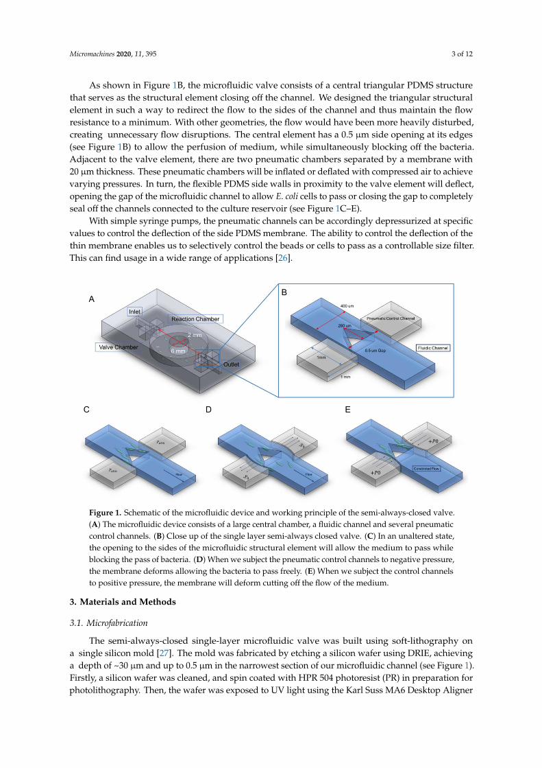
Our device is designed to maintain the E. coli cells viable for 3 h with running medium.Consequently, we designed a large reservoir where sensing bacteria would grow with the samplemedium (see Figure 1A). The central reservoir has an approximate volume of 1 µL connected by twochannels measuring 400 µm in width, ~30 µm in height and several mm in length. The inlet and outletto the central chamber have the side pneumatic channels selectively controlling the flow of the mediumor the bacterial sample (see Figure 1A).
Micromachines 2020, 11, 395 3 of 12
As shown in Figure 1B, the microfluidic valve consists of a central triangular PDMS structurethat serves as the structural element closing off the channel. We designed the triangular structuralelement in such a way to redirect the flow to the sides of the channel and thus maintain the flowresistance to a minimum. With other geometries, the flow would have been more heavily disturbed,creating unnecessary flow disruptions. The central element has a 0.5 µm side opening at its edges(see Figure 1B) to allow the perfusion of medium, while simultaneously blocking off the bacteria.Adjacent to the valve element, there are two pneumatic chambers separated by a membrane with20 µm thickness. These pneumatic chambers will be inflated or deflated with compressed air to achievevarying pressures. In turn, the flexible PDMS side walls in proximity to the valve element will deflect,opening the gap of the microfluidic channel to allow E. coli cells to pass or closing the gap to completelyseal off the channels connected to the culture reservoir (see Figure 1C–E).
With simple syringe pumps, the pneumatic channels can be accordingly depressurized at specificvalues to control the deflection of the side PDMS membrane. The ability to control the deflection of thethin membrane enables us to selectively control the beads or cells to pass as a controllable size filter.This can find usage in a wide range of applications [26].
Micromachines 2020, 11, x 3 of 12
element in such a way to redirect the flow to the sides of the channel and thus maintain the flow resistance to a minimum. With other geometries, the flow would have been more heavily disturbed, creating unnecessary flow disruptions. The central element has a 0.5 μm side opening at its edges (see Figure 1B) to allow the perfusion of medium, while simultaneously blocking off the bacteria. Adjacent to the valve element, there are two pneumatic chambers separated by a membrane with 20 μm thickness. These pneumatic chambers will be inflated or deflated with compressed air to achieve varying pressures. In turn, the flexible PDMS side walls in proximity to the valve element will deflect, opening the gap of the microfluidic channel to allow E. coli cells to pass or closing the gap to completely seal off the channels connected to the culture reservoir (see Figure 1C–E).
With simple syringe pumps, the pneumatic channels can be accordingly depressurized at specific values to control the deflection of the side PDMS membrane. The ability to control the deflection of the thin membrane enables us to selectively control the beads or cells to pass as a controllable size filter. This can find usage in a wide range of applications [26].
Figure 1. Schematic of the microfluidic device and working principle of the semi-always-closed valve. (A) The microfluidic device consists of a large central chamber, a fluidic channel and several pneumatic control channels. (B) Close up of the single layer semi-always closed valve. (C) In an unaltered state, the opening to the sides of the microfluidic structural element will allow the medium to pass while blocking the pass of bacteria. (D) When we subject the pneumatic control channels to negative pressure, the membrane deforms allowing the bacteria to pass freely. (E) When we subject the control channels to positive pressure, the membrane will deform cutting off the flow of the medium.
3. Materials and Methods
3.1. Microfabrication
The semi-always-closed single-layer microfluidic valve was built using soft-lithography on a single silicon mold [27]. The mold was fabricated by etching a silicon wafer using DRIE, achieving a depth of ~30 μm and up to 0.5 μm in the narrowest section of our microfluidic channel (see Figure 1). Firstly, a silicon wafer was cleaned, and spin coated with HPR 504 photoresist (PR) in preparation for photolithography. Then, the wafer was exposed to UV light using the Karl Suss MA6 Desktop Aligner (SÜSS MicroTec, Garching, Germany). Once the photoresist mask was developed, we etched for 30 min using DRIE Bosch Process achieving a depth of ~30 μm (see Figure 2A). After the silicon wafer was etched, the PR was stripped, and the silicon wafer was cleaned using H2SO4. Many
Figure 1. Schematic of the microfluidic device and working principle of the semi-always-closed valve.(A) The microfluidic device consists of a large central chamber, a fluidic channel and several pneumaticcontrol channels. (B) Close up of the single layer semi-always closed valve. (C) In an unaltered state,the opening to the sides of the microfluidic structural element will allow the medium to pass whileblocking the pass of bacteria. (D) When we subject the pneumatic control channels to negative pressure,the membrane deforms allowing the bacteria to pass freely. (E) When we subject the control channelsto positive pressure, the membrane will deform cutting off the flow of the medium.
3. Materials and Methods
3.1. Microfabrication
The semi-always-closed single-layer microfluidic valve was built using soft-lithography ona single silicon mold [27]. The mold was fabricated by etching a silicon wafer using DRIE, achievinga depth of ~30 µm and up to 0.5 µm in the narrowest section of our microfluidic channel (see Figure 1).Firstly, a silicon wafer was cleaned, and spin coated with HPR 504 photoresist (PR) in preparation forphotolithography. Then, the wafer was exposed to UV light using the Karl Suss MA6 Desktop Aligner
Micromachines 2020, 11, 395 4 of 12
(SÜSS MicroTec, Garching, Germany). Once the photoresist mask was developed, we etched for 30 minusing DRIE Bosch Process achieving a depth of ~30 µm (see Figure 2A). After the silicon wafer wasetched, the PR was stripped, and the silicon wafer was cleaned using H2SO4. Many previous worksinvolving microfluidics use photoresists such as SU-8 as the master mold. SU-8 is widely used dueto the high aspect ratio this material can achieve. Nonetheless, SU-8 molds degrade rapidly undersuccessive uses. On the other hand, etched Si molds are very robust and can withstand multiple roundsof PDMS casting allowing the user to rapidly prototype PDMS microchannels. Hence, DRIE etchedsilicon is used as the master mold in our work.
Once the silicon stamp was finalized, the silicon wafer was treated with methyltrichlorosilane(MTS) for a few minutes to allow an easy pealing of the PDMS after curing. The surface modificationwas performed by depositing several milliliters of methyltrichlorosilane on a petri dish in an enclosedprocess chamber containing the silicon wafer. The wafer was left in the process chamber for severalminutes to ensure a good surface treatment.
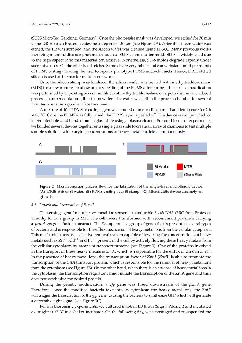
A mixture of 10:1 PDMS to curing agent was poured onto our silicon mold and left to cure for 2 hat 80 ◦C. Once the PDMS was fully cured, the PDMS layer is peeled off. The device is cut, punched forinlet/outlet holes and bonded onto a glass slide using a plasma cleaner. For our biosensor experiments,we bonded several devices together on a single glass slide to create an array of chambers to test multiplesample solutions with varying concentrations of heavy metal particles simultaneously.
Micromachines 2020, 11, x 4 of 12
previous works involving microfluidics use photoresists such as SU-8 as the master mold. SU-8 is widely used due to the high aspect ratio this material can achieve. Nonetheless, SU-8 molds degrade rapidly under successive uses. On the other hand, etched Si molds are very robust and can withstand multiple rounds of PDMS casting allowing the user to rapidly prototype PDMS microchannels. Hence, DRIE etched silicon is used as the master mold in our work
Once the silicon stamp was finalized, the silicon wafer was treated with methyltrichlorosilane (MTS) for a few minutes to allow an easy pealing of the PDMS after curing. The surface modification was performed by depositing several milliliters of methyltrichlorosilane on a petri dish in an enclosed process chamber containing the silicon wafer. The wafer was left in the process chamber for several minutes to ensure a good surface treatment.
A mixture of 10:1 PDMS to curing agent was poured onto our silicon mold and left to cure for 2 h at 80 °C. Once the PDMS was fully cured, the PDMS layer is peeled off. The device is cut, punched for inlet/outlet holes and bonded onto a glass slide using a plasma cleaner. For our biosensor experiments, we bonded several devices together on a single glass slide to create an array of chambers to test multiple sample solutions with varying concentrations of heavy metal particles simultaneously.
Figure 2. Microfabrication process flow for the fabrication of the single-layer microfluidic device. (A) DRIE etch of Si wafer. (B) PDMS casting over Si stamp. (C) Microfluidic device assembly on glass slide.
3.2. Growth and Preparation of E. coli
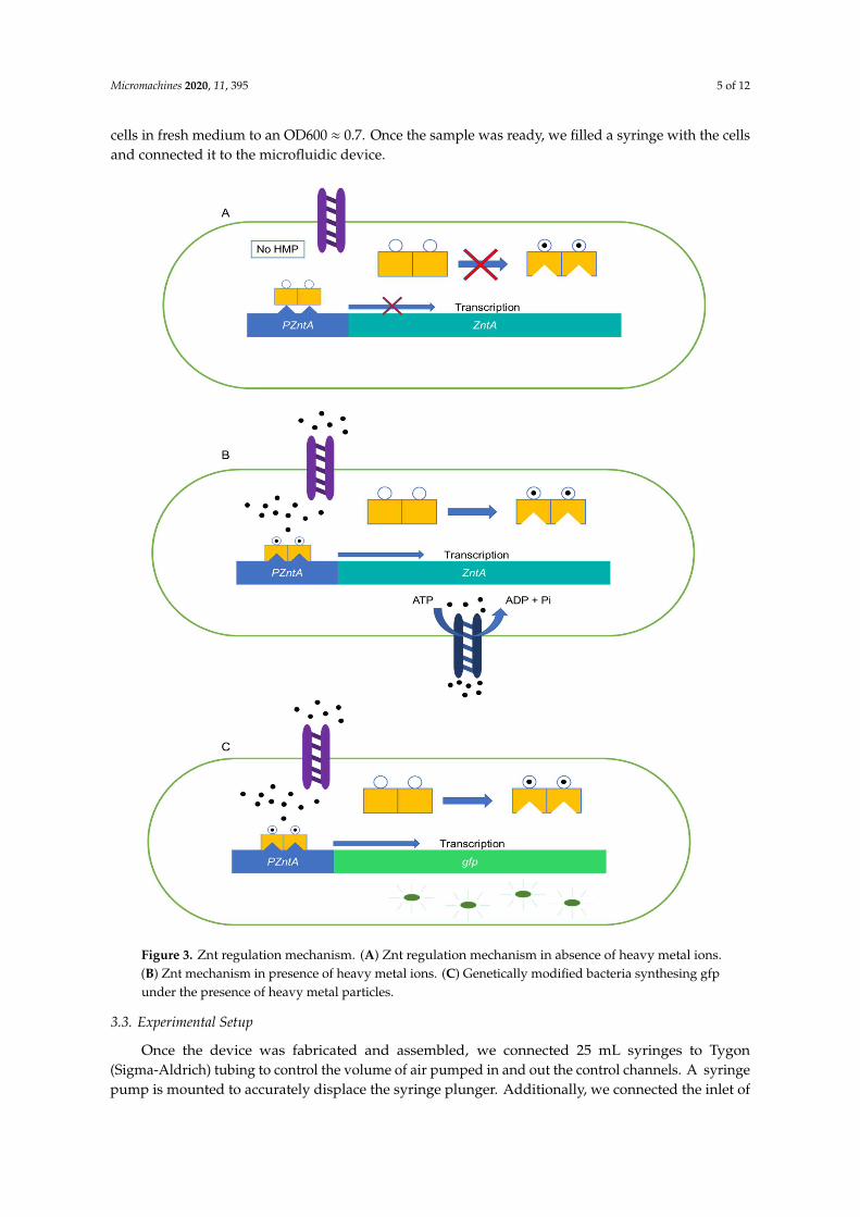
The sensing agent for our heavy-metal-ion sensor is an inducible E.coli DH5αPRO from Professor Timothy K. Lu’s group in MIT. The cells were transformed with recombinant plasmids carrying a pzntA-gfp gene fusion construct. The Znt operon is a group of genes that is present in several types of bacteria and is responsible for the efflux mechanism of heavy metal ions from the cellular cytoplasm. This mechanism acts as a selective removal system capable of lowering the concentrations of heavy metals such as Zn2+, Cd2+ and Pb2+ present in the cell by actively flowing these heavy metals from the cellular cytoplasm by means of transport proteins (see Figure 3). One of the proteins involved in the transport of these heavy metals is zntA, which is responsible for the efflux of Zinc in E.coli. In the presence of heavy metal ions, the transcription factor of ZntA (ZntR) is able to promote the transcription of the zntA transport protein, which is responsible for the removal of heavy metal ions from the cytoplasm (see Figure 3B). On the other hand, when there is an absence of heavy metal ions in the cytoplasm, the transcription regulator cannot initiate the transcription of the ZntA gene and thus does not synthesize the desired protein.
During the genetic modification, a gfp gene was fused downstream of the pzntA gene. Therefore, once the modified bacteria take into its cytoplasm the heavy metal ions, the ZntR will trigger the transcription of the gfp gene, causing the bacteria to synthesize GFP which will generate a detectable light signal (see Figure 3C).
For our biosensing experiments, we cultured E. coli in LB Broth (Sigma-Aldrich) and incubated overnight at 37 °C in a shaker-incubator. On the following day, we centrifuged and resuspended the cells in fresh medium to an OD600 ≈ 0.7. Once the sample was ready, we filled a syringe with the cells and connected it to the microfluidic device.
Figure 2. Microfabrication process flow for the fabrication of the single-layer microfluidic device.(A) DRIE etch of Si wafer. (B) PDMS casting over Si stamp. (C) Microfluidic device assembly onglass slide.
3.2. Growth and Preparation of E. coli
The sensing agent for our heavy-metal-ion sensor is an inducible E. coli DH5αPRO from ProfessorTimothy K. Lu’s group in MIT. The cells were transformed with recombinant plasmids carryinga pzntA-gfp gene fusion construct. The Znt operon is a group of genes that is present in several typesof bacteria and is responsible for the efflux mechanism of heavy metal ions from the cellular cytoplasm.This mechanism acts as a selective removal system capable of lowering the concentrations of heavymetals such as Zn2+, Cd2+ and Pb2+ present in the cell by actively flowing these heavy metals fromthe cellular cytoplasm by means of transport proteins (see Figure 3). One of the proteins involvedin the transport of these heavy metals is zntA, which is responsible for the efflux of Zinc in E. coli.In the presence of heavy metal ions, the transcription factor of ZntA (ZntR) is able to promote thetranscription of the zntA transport protein, which is responsible for the removal of heavy metal ionsfrom the cytoplasm (see Figure 3B). On the other hand, when there is an absence of heavy metal ions inthe cytoplasm, the transcription regulator cannot initiate the transcription of the ZntA gene and thusdoes not synthesize the desired protein.
During the genetic modification, a gfp gene was fused downstream of the pzntA gene.Therefore, once the modified bacteria take into its cytoplasm the heavy metal ions, the ZntRwill trigger the transcription of the gfp gene, causing the bacteria to synthesize GFP which will generatea detectable light signal (see Figure 3C).
For our biosensing experiments, we cultured E. coli in LB Broth (Sigma-Aldrich) and incubatedovernight at 37 ◦C in a shaker-incubator. On the following day, we centrifuged and resuspended the
Micromachines 2020, 11, 395 5 of 12
cells in fresh medium to an OD600 ≈ 0.7. Once the sample was ready, we filled a syringe with the cellsand connected it to the microfluidic device.Micromachines 2020, 11, x 5 of 12
Figure 3. Znt regulation mechanism. (A) Znt regulation mechanism in absence of heavy metal ions. (B) Znt mechanism in presence of heavy metal ions. (C) Genetically modified bacteria synthesing gfp under the presence of heavy metal particles.
3.3. Experimental Setup
Once the device was fabricated and assembled, we connected 25 mL syringes to Tygon (Sigma-Aldrich) tubing to control the volume of air pumped in and out the control channels. A syringe pump is mounted to accurately displace the syringe plunger. Additionally, we connected the inlet of the microfluidic device with Tygon tubing to a supplementary syringe pump to control the flow rate of our medium and cell sample.
With syringe pumps, the pressure in the pneumatic control channels changes according to following equations.
Figure 3. Znt regulation mechanism. (A) Znt regulation mechanism in absence of heavy metal ions.(B) Znt mechanism in presence of heavy metal ions. (C) Genetically modified bacteria synthesing gfpunder the presence of heavy metal particles.
3.3. Experimental Setup
Once the device was fabricated and assembled, we connected 25 mL syringes to Tygon(Sigma-Aldrich) tubing to control the volume of air pumped in and out the control channels. A syringepump is mounted to accurately displace the syringe plunger. Additionally, we connected the inlet of

Micromachines 2020, 11, 395 6 of 12
the microfluidic device with Tygon tubing to a supplementary syringe pump to control the flow rate ofour medium and cell sample.
With syringe pumps, the pressure in the pneumatic control channels changes according tofollowing equations.
P f inal =P0·V0
V f inal
∆P = P f inal − P0 = P0·1
V0∆V − 1
Where P0 is the atmospheric pressure, which is also the pressure in the main fluidic channelwithout fluid. ∆P is the pressure difference across the membrane. By controlling the ratio of the airvolume change in the side channel, this pressure difference can be precisely set. In our experiments,the syringe volume varies from 0 mL to 25 mL. Hence, the pressure difference varies from 0 to ~97kPa. With the syringe pumps, the single-layer valves in this device can be accurately controlledwithout using more complicated electropneumatic systems such as solenoid valves and compressedgas canisters.
For our Cadmium sensing experiment, we seeded the reaction chambers with the recombinantE. coli by opening the valve of the inlet. Once the growth chamber was successfully seeded, thevalve was kept in its rest state and we perfused medium into the chamber alongside a sample ofCadmium heavy metal ions. We kept the device at room temperature and measured the resultingfluorescence with a fluorescence microscope 3 h later (Nikon Eclipse Ni-U, Nikon, Tokyo, Japan).Alternatively, to quantify the temporal evolution of the biosensor, we measured the fluorescence overa period 3 h in 15-min intervals. The full experimental setup containing the syringe pumps to controlthe actuation of the microfluidic device can be observed in Figure 4.
Micromachines 2020, 11, x 6 of 12
𝑃 =𝑃 ∙ 𝑉
𝑉
∆𝑃 = 𝑃 − 𝑃 = 𝑃 ∙1
𝑉∆𝑉
− 1
Where 𝑃 is the atmospheric pressure, which is also the pressure in the main fluidic channel without fluid. ∆P is the pressure difference across the membrane. By controlling the ratio of the air volume change in the side channel, this pressure difference can be precisely set. In our experiments, the syringe volume varies from 0 mL to 25 mL. Hence, the pressure difference varies from 0 to ~97 kPa. With the syringe pumps, the single-layer valves in this device can be accurately controlled without using more complicated electropneumatic systems such as solenoid valves and compressed gas canisters.
For our Cadmium sensing experiment, we seeded the reaction chambers with the recombinant E. coli by opening the valve of the inlet. Once the growth chamber was successfully seeded, the valve was kept in its rest state and we perfused medium into the chamber alongside a sample of Cadmium heavy metal ions. We kept the device at room temperature and measured the resulting fluorescence with a fluorescence microscope 3 h later (Nikon Eclipse Ni-U, Nikon, Tokyo, Japan). Alternatively, to quantify the temporal evolution of the biosensor, we measured the fluorescence over a period 3 h in 15-min intervals. The full experimental setup containing the syringe pumps to control the actuation of the microfluidic device can be observed in Figure 4.
Figure 4. Experimental setup containing the syringe pumps to actuate the device.
4. Results
4.1. Valve Performance
Microscope images of the silicon mold and the fabricated PDMS valve device are shown in Figures 4A–E. The 0.5μm gap is visible along with the 20 μm thick membrane. Figure 4C shows the membrane at the rest pressure. Figure 4D and 4E show microscope images of the membrane with a negative and positive actuation pressure respectively. The membrane experiences its greatest deformation at the center in the vertical direction. Therefore, it exhibits a bulging shape with a
Figure 4. Experimental setup containing the syringe pumps to actuate the device.

Micromachines 2020, 11, 395 7 of 12
4. Results
4.1. Valve Performance
Microscope images of the silicon mold and the fabricated PDMS valve device are shown inFigure 5A–E. The 0.5µm gap is visible along with the 20 µm thick membrane. Figure 5C shows themembrane at the rest pressure. Figure 5D,E show microscope images of the membrane with a negativeand positive actuation pressure respectively. The membrane experiences its greatest deformation atthe center in the vertical direction. Therefore, it exhibits a bulging shape with a negative pressure.The microscope image shows clear thickening of the membrane in Figure 5E when the deformationis large.
The functionality of the valve can be visualized with the help of fluorescent beads. In theseexperiments, polystyrene beads of different sizes were added to the fluidic channel. Sizes of choicewere 0.2 µm, 2.5 µm, 5 µm and 10 µm. We can observe that 0.2 µm beads flow without any difficultythrough the 0.5 µm gap (see Figure 5A) with the valve at rest. However, with larger beads such as2.5 µm and 5 µm the beads will get trapped at the sides of the fluidic channel (Figure 5C) with the valveat rest. It is only when the negative pressure in the side channel increases to deflect the membranewide enough so that these beads will be able to flow (Figure 5D). For beads measuring 10 µm, we canobserve a flow in the fluid, which is evidenced by the blurred image of a moving bead in the circledarea (see Figure 5D). But the beads remain completely blocked even with the negative pressure addedto the side channels. This is because the size of the beads has already exceeded the maximum possibledeflection of PDMS side wall in our design.
Micromachines 2020, 11, x 7 of 12
negative pressure. The microscope image shows clear thickening of the membrane in Figure 4E when the deformation is large.
The functionality of the valve can be visualized with the help of fluorescent beads. In these experiments, polystyrene beads of different sizes were added to the fluidic channel. Sizes of choice were 0.2 μm, 2.5 μm, 5 μm and 10 μm. We can observe that 0.2 μm beads flow without any difficulty through the 0.5 μm gap (see Figure 5A) with the valve at rest. However, with larger beads such as 2.5 μm and 5 μm the beads will get trapped at the sides of the fluidic channel (Figure 5C) with the valve at rest. It is only when the negative pressure in the side channel increases to deflect the membrane wide enough so that these beads will be able to flow (Figure 5D). For beads measuring 10 μm, we can observe a flow in the fluid, which is evidenced by the blurred image of a moving bead in the circled area (see Figure 5D). But the beads remain completely blocked even with the negative pressure added to the side channels. This is because the size of the beads has already exceeded the maximum possible deflection of PDMS side wall in our design.
Alternatively, other forms of actuation with the use of rubber bulbs could be possible as long as, the actuation of the valve can provide enough pressure difference. In the case of rubber bulbs, enough pressure can be generated. However, rubber bulbs do not have an adequate tubing interface such as Luer lock syringes, resulting in a vulnerable sealing.
Figure 5. Brightfield images of silicon micromachined mold (A,B) and PDMS single layer valve under different actuation pressures (C,D). (A) Brightfield image of micromachined silicon stamp for soft lithography. (B) 100x magnification of the corner of our structural element. As it can be observed the side opening measures ~0.5 μm. (C) Brightfield image of our microfluidic valve in the rest state. (D) Brightfield image of our microfluidic valve actuated at a negative pressure of 0.5 atm. (E) Brightfield image of our microfluidic valve actuated with a positive pressure of 1 atm.
4.3. Heavy Metal Testing with the Microfluidic Device
E. coli were seeded in the growth chamber after opening the valve (see Figure 6A). The cells are cultured over 3 h with running medium through the 0.5 μm gap with the valves at rest. Brightfield and fluorescence microscope images in Figure 6 show that the cells are viable and properly perfused with medium to support growth and synthesis of GFP over the duration of the 3-h inducing period.
Figure 5. Brightfield images of silicon micromachined mold (A,B) and PDMS single layer valve underdifferent actuation pressures (C,D). (A) Brightfield image of micromachined silicon stamp for softlithography. (B) 100x magnification of the corner of our structural element. As it can be observedthe side opening measures ~0.5 µm. (C) Brightfield image of our microfluidic valve in the rest state.(D) Brightfield image of our microfluidic valve actuated at a negative pressure of 0.5 atm. (E) Brightfieldimage of our microfluidic valve actuated with a positive pressure of 1 atm.
Micromachines 2020, 11, 395 8 of 12
Alternatively, other forms of actuation with the use of rubber bulbs could be possible as longas, the actuation of the valve can provide enough pressure difference. In the case of rubber bulbs,enough pressure can be generated. However, rubber bulbs do not have an adequate tubing interfacesuch as Luer lock syringes, resulting in a vulnerable sealing.
4.2. Heavy Metal Testing with the Microfluidic Device
E. coli were seeded in the growth chamber after opening the valve (see Figure 6A). The cells arecultured over 3 h with running medium through the 0.5 µm gap with the valves at rest. Brightfieldand fluorescence microscope images in Figure 6 show that the cells are viable and properly perfusedwith medium to support growth and synthesis of GFP over the duration of the 3-h inducing period.
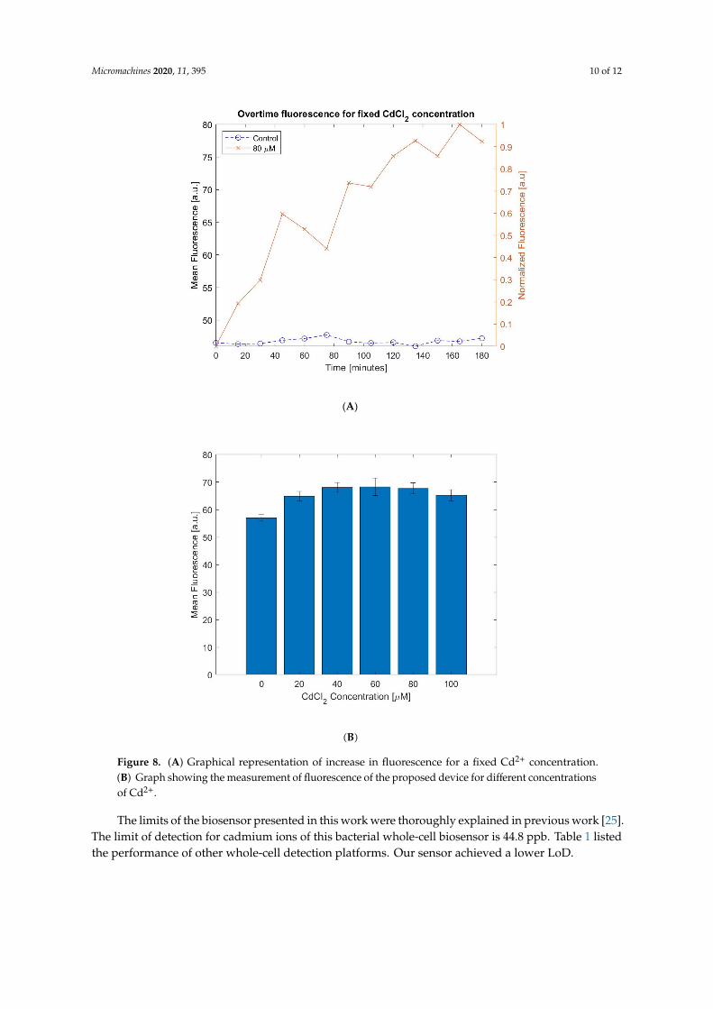
Once the whole-cell biosensor was seeded in the chamber we induced the cells with cadmium ions.We measured the fluorescence signal over a 3-h period in 15-min intervals. This experiment allowedus to quantify the response time of our biosensor. As recombinant E. coli spontaneously generateGFP, a control experiment is applied to measure the fluorescence of E. coli cells without adding heavymetal ion solution. Over time, these cells will generate a signal bias that must be considered whenanalyzing the sample. As it can be observed in Figure 7A, the fluorescence generated by our whole-cellbiosensor increases overtime. The results show that 1.5 h after inducing the biosensor, the level offluorescence is measurable. Additionally, it can also be seen that during a 3h incubation, the levels ofGFP do not increase significantly for the control sample. This is because 3 h is not enough to detecta measurable increase in spontaneous GFP. Bacteria divide and populate rapidly over time. From ourcontrol experiments visualized on Figure 7A, we can conclude that there is not a notable populationincrease over a period of 3 h. This can be explained since the sample seeded into the growth chamberhas an initial high number of cells (With an OD600 nm of 0.7, there is a bacterial concentration of5.6 × 108 cells/mL. The 1 µL chamber could contain a total of 560,000 cells.) As the volume is fixedand the cells are tightly packed in our growth chamber, bacterial cells do not expand aggressively likethey would do otherwise. Therefore, since the number of cells does not increase rapidly over a 3-hperiod and the spontaneous GFP is not generated fast enough, the baseline of our sensor does notincrease overtime.
High concentrations of cells such as the ones used in this work are needed in whole-cell biosensingsince they can reduce the response time, leading to shorter detection and incubation times. In theevent of seeding the chambers with a lower concentration of cells, the possibility of detecting lowconcentrations of target ions in a short incubation time decreases notably [25].
Whole-cell sensors such as the one presented in this work accumulate GFP in their cytoplasm.A notable disadvantage of these biosensors is their inability to remove GFP from their cytoplasm,accumulating over time. To overcome this problem, the culture must be discarded and reseeded todetect additional samples containing heavy metal ions. This is the reason why it is important to havean automatic and simple bacterial microreactor.
On the other hand, Figure 7B shows levels of fluorescence with different concentration of cadmiumafter inducing for 3 h. The values shown on this graph represent the mean and the standard error of thehistogram of a fluorescence microscopy image. The experiments on Figure 8B were repeated 4 timeson a total of 24 chips. The experiments were run in parallel and fluorescence measurements weretaken at three different locations per chip to reduce the variation due to the imaging spot. Our resultsindicate the fluorescence increases linearly with an increasing cadmium concentration below 40 µM.Beyond 80 µM, our measurements show a clear drop of fluorescence. This phenomenon occurs due tocytotoxicity of cadmium [21]. At higher levels of Cd2+ the E. coli cells will undergo cellular death dueto the high concentration of heavy metal ions in the solution [28]. As it can be observed in Figure 8B,the fluorescence signal peaks at around 60 µM. Nonetheless, between 40 µM to 80 µM, our systemshows less sensitivity. This is mainly because our imaging system can only record the fluorescencefrom a small spot in the reaction chamber for each measurement. Hence, the result is subjected to theminiature cell population variation at the imaging spot in Figure 8B. Using an imaging system with

Micromachines 2020, 11, 395 9 of 12
larger field of view, the imaging uniformity could be further improved. Even with this limitation,Figure 8B records similar trends as shown in previous literature [24,25,28]. The limit-of-detection(LOD) of this sensor is about 44.8 ppb for Cd2+ [25].Micromachines 2020, 11, x 9 of 12
Figure 6. Fluorescent images depicting the flow of fluorescent bead through the semi-always-closed single-layer valve. (A) 0.2 μm fluorescent beads diffusing through the valve side opening. (B) 10 μm fluorescent beads getting trapped in the microfluidic valve, we can see that the fluid continues to flow due to the shade of a flowing bead (red circle). (C) 5 μm fluorescent bead initially getting trapped before actuation of the single layer valve. (D) 5 μm fluorescent bead passing through the single layer valve once the side wall was deflected.
Figure 7. Brightfield and Fluorescence time lapse of cells in the microfluidic growth chamber. (A) Brightfield image at t = 0 s. (B) Brightfield image at t = 1.5 h. (C) Brightfield image at t = 3 h. (D) Fluorescence image at t = 0 s. (E) Fluorescence image at t = 1.5 h. (F) Fluorescence image at t = 3 h.
Figure 6. Fluorescent images depicting the flow of fluorescent bead through the semi-always-closedsingle-layer valve. (A) 0.2 µm fluorescent beads diffusing through the valve side opening. (B) 10 µmfluorescent beads getting trapped in the microfluidic valve, we can see that the fluid continues to flowdue to the shade of a flowing bead (red circle). (C) 5 µm fluorescent bead initially getting trappedbefore actuation of the single layer valve. (D) 5 µm fluorescent bead passing through the single layervalve once the side wall was deflected.
Micromachines 2020, 11, x 9 of 12
Figure 6. Fluorescent images depicting the flow of fluorescent bead through the semi-always-closed single-layer valve. (A) 0.2 μm fluorescent beads diffusing through the valve side opening. (B) 10 μm fluorescent beads getting trapped in the microfluidic valve, we can see that the fluid continues to flow due to the shade of a flowing bead (red circle). (C) 5 μm fluorescent bead initially getting trapped before actuation of the single layer valve. (D) 5 μm fluorescent bead passing through the single layer valve once the side wall was deflected.
Figure 7. Brightfield and Fluorescence time lapse of cells in the microfluidic growth chamber. (A) Brightfield image at t = 0 s. (B) Brightfield image at t = 1.5 h. (C) Brightfield image at t = 3 h. (D) Fluorescence image at t = 0 s. (E) Fluorescence image at t = 1.5 h. (F) Fluorescence image at t = 3 h.
Figure 7. Brightfield and Fluorescence time lapse of cells in the microfluidic growth chamber.(A) Brightfield image at t = 0 s. (B) Brightfield image at t = 1.5 h. (C) Brightfield image at t = 3 h.(D) Fluorescence image at t = 0 s. (E) Fluorescence image at t = 1.5 h. (F) Fluorescence image at t = 3 h.
Micromachines 2020, 11, 395 10 of 12Micromachines 2020, 11, x 10 of 12
(A)
(B)
Figure 8: (A) Graphical representation of increase in fluorescence for a fixed Cd2+ concentration. (B) Graph showing the measurement of fluorescence of the proposed device for different concentrationsof Cd2+.
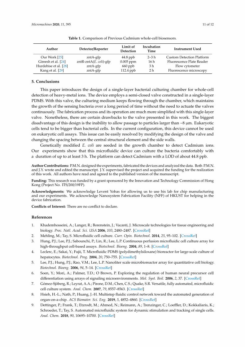
The limits of the biosensor presented in this work were thoroughly explained in previous work [25]. The limit of detection for cadmium ions of this bacterial whole-cell biosensor is 44.8 ppb. Table1 listed the performance of other whole-cell detection platforms. Our sensor achieved a lower LoD.
Figure 8. (A) Graphical representation of increase in fluorescence for a fixed Cd2+ concentration.(B) Graph showing the measurement of fluorescence of the proposed device for different concentrationsof Cd2+.
The limits of the biosensor presented in this work were thoroughly explained in previous work [25].The limit of detection for cadmium ions of this bacterial whole-cell biosensor is 44.8 ppb. Table 1 listedthe performance of other whole-cell detection platforms. Our sensor achieved a lower LoD.
Micromachines 2020, 11, 395 11 of 12
Table 1. Comparison of Previous Cadmium whole-cell biosensors.
Author Detector/Reporter Limit ofDetection
IncubationTime Instrument Used
Our Work [25] zntA-gfp 44.8 ppb 2–3 h Custom Detection PlatformGireesh et al. [24] zntR-zntA(E. coli)-gfp 0.005 ppm 16 h Fluorescence Plate Reader
Hurdebise et al. [28] zntA-gfp 660 ppb 3 h Flow cytometerKang et al. [29] zntA-gfp 112.4 ppb 2 h Fluorescence microscopy
5. Conclusions
This paper introduces the design of a single-layer bacterial culturing chamber for whole-celldetection of heavy-metal ions. The device employs a semi-closed valve constructed in a single-layerPDMS. With this valve, the culturing medium keeps flowing through the chamber, which maintainsthe growth of the sensing bacteria over a long period of time without the need to actuate the valvescontinuously. The fabrication process and its operation are much more simplified with this single-layervalve. Nonetheless, there are certain drawbacks to the valve presented in this work. The biggestdisadvantage of this design is the inability to allow passage to particles larger than ~8 µm. Eukaryoticcells tend to be bigger than bacterial cells. In the current configuration, this device cannot be usedon eukaryotic cell assays. This issue can be easily resolved by modifying the design of the valve andchanging the spacing between the central structural element and the side walls.
Genetically modified E. coli are seeded in the growth chamber to detect Cadmium ions.Our experiments show that this microfluidic device can culture the bacteria comfortably witha duration of up to at least 3 h. The platform can detect Cadmium with a LOD of about 44.8 ppb.
Author Contributions: P.M.N. designed the experiments, fabricated the devices and analyzed the data. Both P.M.N.and J.Y. wrote and edited the manuscript. J.Y. supervised the project and acquired the funding for the realizationof this work. All authors have read and agreed to the published version of the manuscript.
Funding: This research was funded by a grant sponsored by the Innovation and Technology Commission of HongKong (Project No. ITS/200/19FP).
Acknowledgments: We acknowledge Levent Yobas for allowing us to use his lab for chip manufacturingand our experiments. We acknowledge Nanosystem Fabrication Facility (NFF) of HKUST for helping in thedevice fabrication.
Conflicts of Interest: There are no conflict to declare.
References
1. Khademhosseini, A.; Langer, R.; Borenstein, J.; Vacanti, J. Microscale technologies for tissue engineering andbiology. Proc. Natl. Acad. Sci. USA 2006, 103, 2480–2487. [CrossRef]
2. Mehling, M.; Tay, S. Microfluidic cell culture. Curr. Opin. Biotechnol. 2014, 25, 95–102. [CrossRef]3. Hung, P.J.; Lee, P.J.; Sabounchi, P.; Lin, R.; Lee, L.P. Continuous perfusion microfluidic cell culture array for
high-throughput cell-based assays. Biotechnol. Bioeng. 2004, 89, 1–8. [CrossRef]4. Leclerc, E.; Sakai, Y.; Fujii, T. Microfluidic PDMS (polydimethylsiloxane) bioreactor for large-scale culture of
hepatocytes. Biotechnol. Prog. 2004, 20, 750–755. [CrossRef]5. Lee, P.J.; Hung, P.J.; Rao, V.M.; Lee, L.P. Nanoliter scale microbioreactor array for quantitative cell biology.
Biotechnol. Bioeng. 2006, 94, 5–14. [CrossRef]6. Soen, Y.; Mori, A.; Palmer, T.D.; O Brown, P. Exploring the regulation of human neural precursor cell
differentiation using arrays of signaling microenvironments. Mol. Syst. Boil. 2006, 2, 37. [CrossRef]7. Gómez-Sjöberg, R.; Leyrat, A.A.; Pirone, D.M.; Chen, C.S.; Quake, S.R. Versatile, fully automated, microfluidic
cell culture system. Anal. Chem. 2007, 79, 8557–8563. [CrossRef]8. Hsieh, H.-L.; Nath, P.; Huang, J.-H. Multistep fluidic control network toward the automated generation of
organ-on-a-chip. ACS Biomater. Sci. Eng. 2019, 5, 4852–4860. [CrossRef]9. Dettinger, P.; Frank, T.; Etzrodt, M.; Ahmed, N.; Reimann, A.; Trenzinger, C.; Loeffler, D.; Kokkaliaris, K.;
Schroeder, T.; Tay, S. Automated microfluidic system for dynamic stimulation and tracking of single cells.Anal. Chem. 2018, 90, 10695–10700. [CrossRef]
Micromachines 2020, 11, 395 12 of 12
10. Wang, C.; Tanataweethum, N.; Karnik, S.; Bhushan, A. Novel microfluidic colon with an extracellular matrixmembrane. ACS Biomater. Sci. Eng. 2018, 4, 1377–1385. [CrossRef]
11. Liu, W.; Xu, J.; Li, T.; Zhao, L.; Ma, C.; Shen, S.; Wang, J. Monitoring tumor response to anticancer drugsusing stable three-dimensional culture in a recyclable microfluidic platform. Anal. Chem. 2015, 87, 9752–9760.[CrossRef]
12. Topiwala, H.H.; Hamer, G. Effect of wall growth in steady-state continuous cultures. Biotechnol. Bioeng.1971, 13, 919–922. [CrossRef]
13. Balagaddé, F.K.; You, L.; Hansen, C.L.; Arnold, F.H.; Quake, S.R. Long-term monitoring of bacteria undergoingprogrammed population control in a microchemostat. Science 2005, 309, 137–140. [CrossRef]
14. Srinivasan, A.; Leung, K.P.; Lopez-Ribot, J.L.; Ramasubramanian, A.K. High-throughput nano-biofilmmicroarray for antifungal drug discovery. mBio 2013, 4, e00331-13. [CrossRef]
15. Kim, M.; Bae, J.; Kim, T. Long-term and programmable bacterial subculture in completely automatedmicrochemostats. Anal. Chem. 2017, 89, 9676–9684. [CrossRef]
16. Jian, X.; Guo, X.; Wang, J.; Tan, Z.L.; Xing, X.-H.; Wang, L.; Zhang, C. Microbial microdroplet culturesystem (MMC): An integrated platform for automated, high-throughput microbial cultivation and adaptiveevolution. Biotechnol. Bioeng. 2020. [CrossRef]
17. Araci, I.E.; Quake, S.R. Microfluidic very large scale integration (mVLSI) with integrated micromechanicalvalves. Lab Chip 2012, 12, 2803. [CrossRef]
18. Abate, A.R.; Agresti, J.J.; Weitz, D.A. Microfluidic sorting with high-speed single-layer membrane valves.Appl. Phys. Lett. 2010, 96, 203509. [CrossRef]
19. Kim, D.; Berlin, A.A. Microfluidic operations using deformable polymer membranes fabricated by singlelayer soft lithography. Lab Chip 2005, 5, 350–354.
20. Abate, A.R.; Weitz, D.A. Single-layer membrane valves for elastomeric microfluidic devices. Appl. Phys. Lett.2008, 92, 243509. [CrossRef]
21. Kim, J.; Kang, M.; Jensen, E.C.; A Mathies, R. Lifting gate polydimethylsiloxane microvalves and pumps formicrofluidic control. Anal. Chem. 2012, 84, 2067–2071. [CrossRef]
22. Schudel, B.R.; Choi, C.J.; Cunningham, B.T.; Kenis, P.J.A. Microfluidic chip for combinatorial mixing andscreening of assays. Lab Chip 2009, 9, 1676. [CrossRef] [PubMed]
23. Harada, M. Minamata disease: Methylmercury poisoning in japan caused by environmental pollution.Crit. Rev. Toxicol. 1995, 25, 1–24. [CrossRef] [PubMed]
24. Gireesh-Babu, P.; Chaudhari, A. Development of a broad-spectrum fluorescent heavy metal bacterialbiosensor. Mol. Boil. Rep. 2012, 39, 11225–11229. [CrossRef] [PubMed]
25. Zhang, C.; Siddiqui, S.; Navarrete, P.M.; Yuan, J. An integrated whole-cell detection platform for heavy metalions. IEEE Sens. J. 2020, 20, 1. [CrossRef]
26. Rho, H.; Yang, Y.; Ottens, M.; Hanke, A.T.; Terstappen, L.W.; Gardeniers, H.J.G.E. Programmable v-typevalve for cell and particle manipulation in microfluidic devices. Lab Chip 2016, 16, 305–311. [CrossRef]
27. Duffy, D.C.; McDonald, J.C.; Schueller, O.J.A.; Whitesides, G.M. Rapid prototyping of microfluidic systemsin poly (dimethylsiloxane). Anal. Chem. 1998, 70, 4974–4984. [CrossRef]
28. Hurdebise, Q.; Tarayre, C.; Fischer, C.; Colinet, G.; Hiligsmann, S.; Delvigne, F. Determination of zinc,cadmium and lead bioavailability in contaminated soils at the single-cell level by a combination of whole-cellbiosensors and flow cytometry. Sensors 2015, 15, 8981–8999. [CrossRef]
29. Kang, Y.; Lee, W.; Jang, G.; Kim, B.-G.; Yoon, Y. Modulating the sensing properties of Escherichia coli-basedbioreporters for cadmium and mercury. Appl. Microbiol. Biotechnol. 2018, 102, 4863–4872. [CrossRef]
© 2020 by the authors. Licensee MDPI, Basel, Switzerland. This article is an open accessarticle distributed under the terms and conditions of the Creative Commons Attribution(CC BY) license (http://creativecommons.org/licenses/by/4.0/).