a simulink library for drilling modeling, simulation, and
TRANSCRIPT

A Simulink library for Drilling Modeling, Simulation and Control
16th November 2021
Rajat Dixit
Wells Engineer (Drilling Mechanics) – ExxonMobil
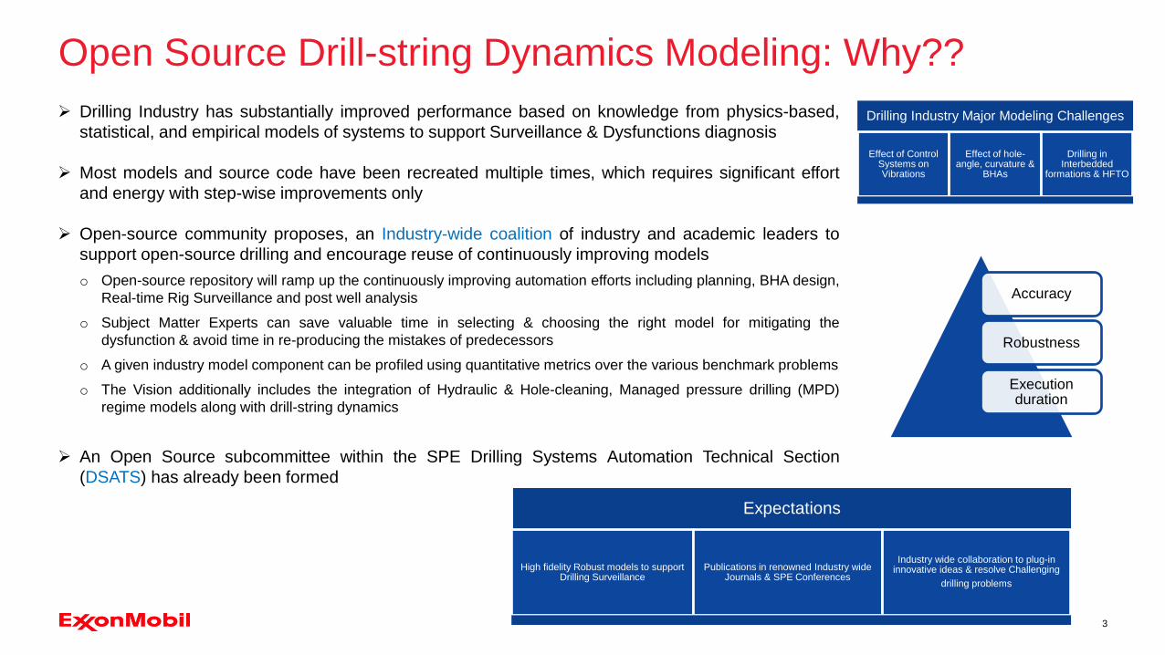
➢ Drilling Industry has substantially improved performance based on knowledge from physics-based,
statistical, and empirical models of systems to support Surveillance & Dysfunctions diagnosis
➢ Most models and source code have been recreated multiple times, which requires significant effort
and energy with step-wise improvements only
➢ Open-source community proposes, an Industry-wide coalition of industry and academic leaders to
support open-source drilling and encourage reuse of continuously improving models
o Open-source repository will ramp up the continuously improving automation efforts including planning, BHA design,
Real-time Rig Surveillance and post well analysis
o Subject Matter Experts can save valuable time in selecting & choosing the right model for mitigating the
dysfunction & avoid time in re-producing the mistakes of predecessors
o A given industry model component can be profiled using quantitative metrics over the various benchmark problems
o The Vision additionally includes the integration of Hydraulic & Hole-cleaning, Managed pressure drilling (MPD)
regime models along with drill-string dynamics
➢ An Open Source subcommittee within the SPE Drilling Systems Automation Technical Section
(DSATS) has already been formed
Open Source Drill-string Dynamics Modeling: Why??
3
Accuracy
Robustness
Execution duration
Drilling Industry Major Modeling Challenges
Effect of Control Systems on Vibrations
Effect of hole-angle, curvature &
BHAs
Drilling in Interbedded
formations & HFTO
Expectations
High fidelity Robust models to support Drilling Surveillance
Publications in renowned Industry wide Journals & SPE Conferences
Industry wide collaboration to plug-in innovative ideas & resolve Challenging
drilling problems
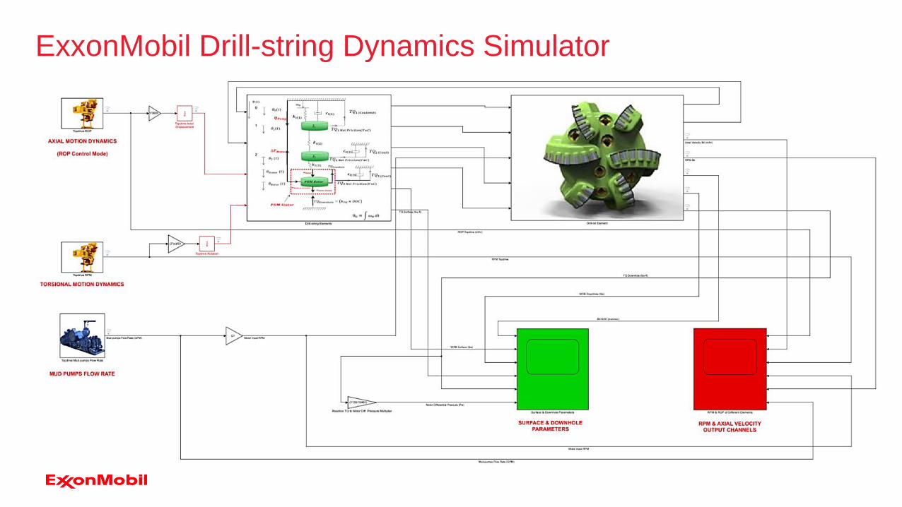
ExxonMobil Drill-string Dynamics Simulator
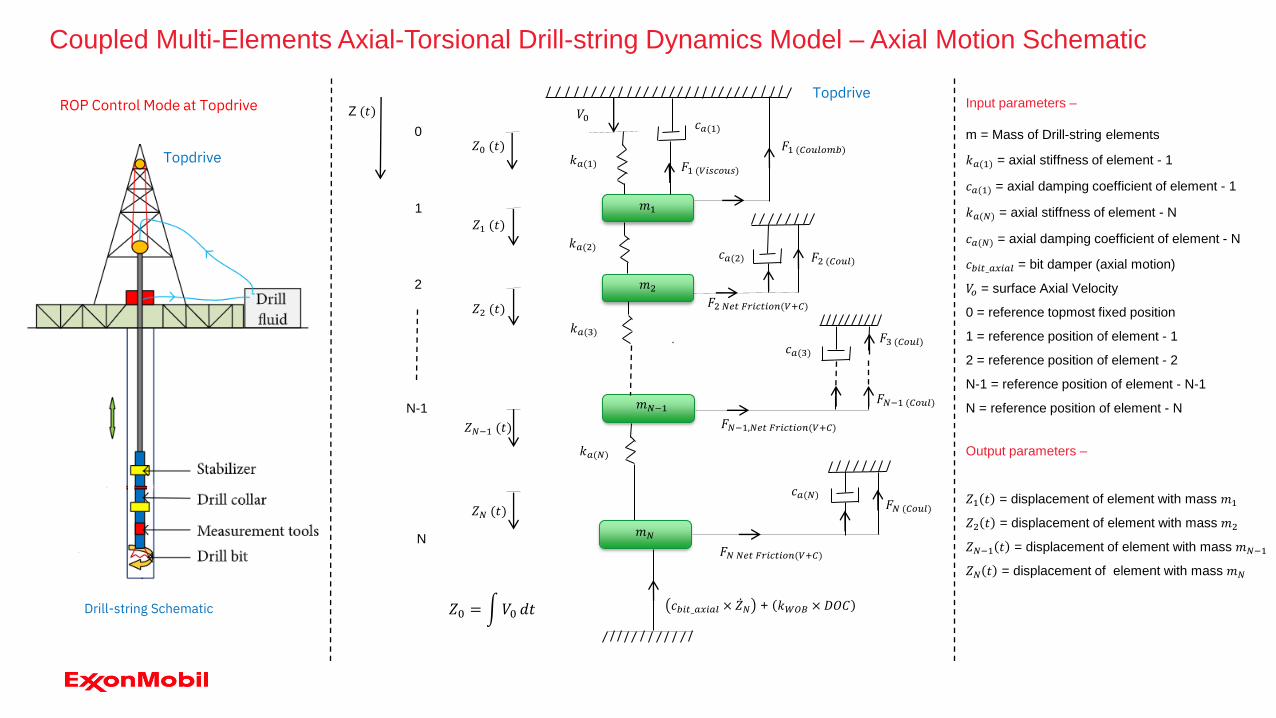
Coupled Multi-Elements Axial-Torsional Drill-string Dynamics Model – Axial Motion Schematic
Input parameters –
m = Mass of Drill-string elements
𝑘𝑎(1) = axial stiffness of element - 1
𝑐𝑎(1) = axial damping coefficient of element - 1
𝑘𝑎(𝑁) = axial stiffness of element - N
𝑐𝑎(𝑁) = axial damping coefficient of element - N
𝑐𝑏𝑖𝑡_𝑎𝑥𝑖𝑎𝑙 = bit damper (axial motion)
𝑉𝑜 = surface Axial Velocity
0 = reference topmost fixed position
1 = reference position of element - 1
2 = reference position of element - 2
N-1 = reference position of element - N-1
N = reference position of element - N
Output parameters –
𝑍1 𝑡 = displacement of element with mass 𝑚1
𝑍2 𝑡 = displacement of element with mass 𝑚2
𝑍𝑁−1 𝑡 = displacement of element with mass 𝑚𝑁−1
𝑍𝑁 𝑡 = displacement of element with mass 𝑚𝑁
0
1
2
N-1
N
𝑘𝑎(1)
𝑘𝑎(2)
𝑚1
𝑚2
𝑚𝑁−1
𝑚𝑁
𝑘𝑎(3)
𝑐𝑎(3)
𝑘𝑎(𝑁)
𝑐𝑎(𝑁)
Z (𝑡)
𝑍1 (𝑡)
𝑍2 (𝑡)
𝑍𝑁−1 (𝑡)
𝑍𝑁 (𝑡)
𝑉0
𝑍0 (𝑡)
𝑐𝑏𝑖𝑡_𝑎𝑥𝑖𝑎𝑙 × ሶ𝑍𝑁 + 𝑘𝑊𝑂𝐵 × 𝐷𝑂𝐶𝑍0 = න𝑉0 𝑑𝑡
𝐹𝑁−1,𝑁𝑒𝑡 𝐹𝑟𝑖𝑐𝑡𝑖𝑜𝑛(𝑉+𝐶)
𝐹3 (𝐶𝑜𝑢𝑙)
𝑐𝑎(2)
𝐹𝑁 (𝐶𝑜𝑢𝑙)
𝐹𝑁 𝑁𝑒𝑡 𝐹𝑟𝑖𝑐𝑡𝑖𝑜𝑛(𝑉+𝐶)
𝐹2 (𝐶𝑜𝑢𝑙)
𝑐𝑎(1)
𝐹1 (𝐶𝑜𝑢𝑙𝑜𝑚𝑏)
𝐹1 (𝑉𝑖𝑠𝑐𝑜𝑢𝑠)
𝐹2 𝑁𝑒𝑡 𝐹𝑟𝑖𝑐𝑡𝑖𝑜𝑛(𝑉+𝐶)
𝐹𝑁−1 (𝐶𝑜𝑢𝑙)
Drill-string Schematic
Topdrive
TopdriveROP Control Mode at Topdrive
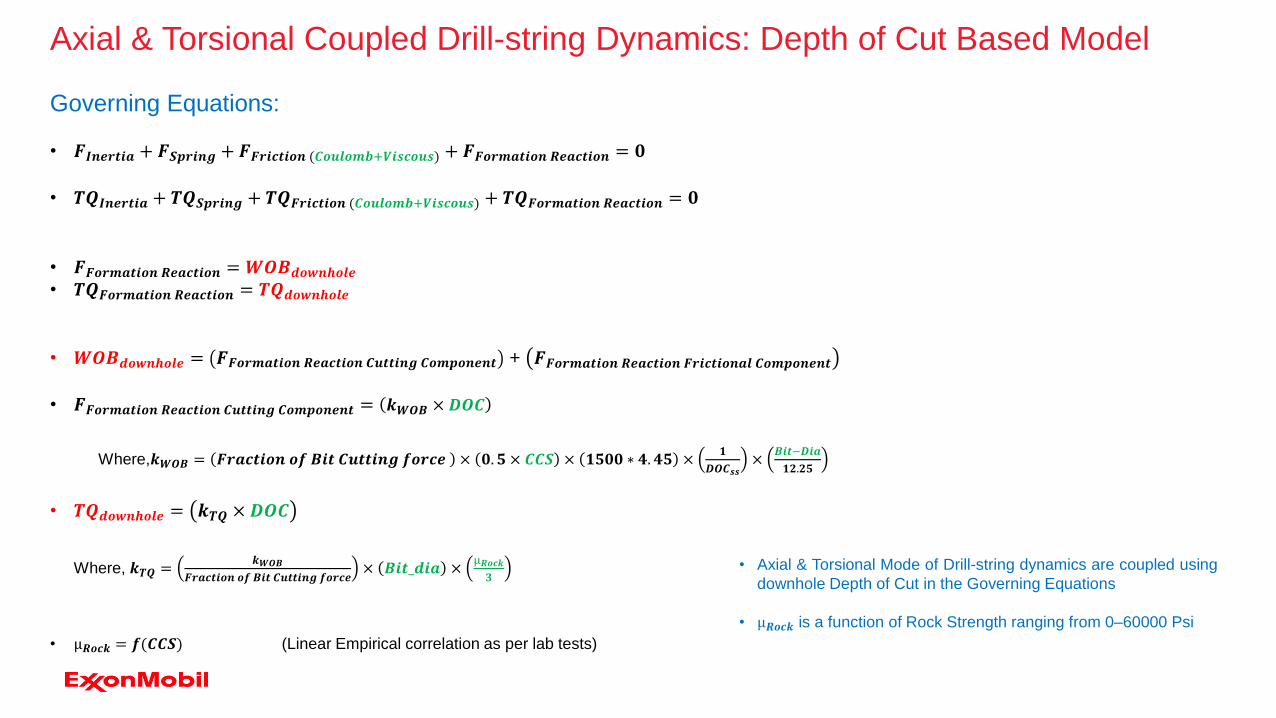
Governing Equations:
• 𝑭𝑰𝒏𝒆𝒓𝒕𝒊𝒂 + 𝑭𝑺𝒑𝒓𝒊𝒏𝒈 + 𝑭𝑭𝒓𝒊𝒄𝒕𝒊𝒐𝒏 (𝑪𝒐𝒖𝒍𝒐𝒎𝒃+𝑽𝒊𝒔𝒄𝒐𝒖𝒔) + 𝑭𝑭𝒐𝒓𝒎𝒂𝒕𝒊𝒐𝒏 𝑹𝒆𝒂𝒄𝒕𝒊𝒐𝒏 = 𝟎
• 𝑻𝑸𝑰𝒏𝒆𝒓𝒕𝒊𝒂 + 𝑻𝑸𝑺𝒑𝒓𝒊𝒏𝒈 + 𝑻𝑸𝑭𝒓𝒊𝒄𝒕𝒊𝒐𝒏 (𝑪𝒐𝒖𝒍𝒐𝒎𝒃+𝑽𝒊𝒔𝒄𝒐𝒖𝒔) + 𝑻𝑸𝑭𝒐𝒓𝒎𝒂𝒕𝒊𝒐𝒏 𝑹𝒆𝒂𝒄𝒕𝒊𝒐𝒏 = 𝟎
• 𝑭𝑭𝒐𝒓𝒎𝒂𝒕𝒊𝒐𝒏 𝑹𝒆𝒂𝒄𝒕𝒊𝒐𝒏 = 𝑾𝑶𝑩𝒅𝒐𝒘𝒏𝒉𝒐𝒍𝒆
• 𝑻𝑸𝑭𝒐𝒓𝒎𝒂𝒕𝒊𝒐𝒏 𝑹𝒆𝒂𝒄𝒕𝒊𝒐𝒏 = 𝑻𝑸𝒅𝒐𝒘𝒏𝒉𝒐𝒍𝒆
• 𝑾𝑶𝑩𝒅𝒐𝒘𝒏𝒉𝒐𝒍𝒆 = 𝑭𝑭𝒐𝒓𝒎𝒂𝒕𝒊𝒐𝒏 𝑹𝒆𝒂𝒄𝒕𝒊𝒐𝒏 𝑪𝒖𝒕𝒕𝒊𝒏𝒈 𝑪𝒐𝒎𝒑𝒐𝒏𝒆𝒏𝒕 + 𝑭𝑭𝒐𝒓𝒎𝒂𝒕𝒊𝒐𝒏 𝑹𝒆𝒂𝒄𝒕𝒊𝒐𝒏 𝑭𝒓𝒊𝒄𝒕𝒊𝒐𝒏𝒂𝒍 𝑪𝒐𝒎𝒑𝒐𝒏𝒆𝒏𝒕
• 𝑭𝑭𝒐𝒓𝒎𝒂𝒕𝒊𝒐𝒏 𝑹𝒆𝒂𝒄𝒕𝒊𝒐𝒏 𝑪𝒖𝒕𝒕𝒊𝒏𝒈 𝑪𝒐𝒎𝒑𝒐𝒏𝒆𝒏𝒕 = 𝒌𝑾𝑶𝑩 × 𝑫𝑶𝑪
Where,𝒌𝑾𝑶𝑩 = 𝑭𝒓𝒂𝒄𝒕𝒊𝒐𝒏 𝒐𝒇 𝑩𝒊𝒕 𝑪𝒖𝒕𝒕𝒊𝒏𝒈 𝒇𝒐𝒓𝒄𝒆 × 𝟎. 𝟓 × 𝑪𝑪𝑺 × 𝟏𝟓𝟎𝟎 ∗ 𝟒. 𝟒𝟓 ×𝟏
𝑫𝑶𝑪𝒔𝒔×
𝑩𝒊𝒕−𝑫𝒊𝒂
𝟏𝟐.𝟐𝟓
• 𝑻𝑸𝒅𝒐𝒘𝒏𝒉𝒐𝒍𝒆 = 𝒌𝑻𝑸 ×𝑫𝑶𝑪
Where, 𝒌𝑻𝑸 =𝒌𝑾𝑶𝑩
𝑭𝒓𝒂𝒄𝒕𝒊𝒐𝒏 𝒐𝒇 𝑩𝒊𝒕 𝑪𝒖𝒕𝒕𝒊𝒏𝒈 𝒇𝒐𝒓𝒄𝒆× 𝑩𝒊𝒕_𝒅𝒊𝒂 ×
μ𝑹𝒐𝒄𝒌
𝟑
• μ𝑹𝒐𝒄𝒌 = 𝒇(𝑪𝑪𝑺) (Linear Empirical correlation as per lab tests)
Axial & Torsional Coupled Drill-string Dynamics: Depth of Cut Based Model
• Axial & Torsional Mode of Drill-string dynamics are coupled using
downhole Depth of Cut in the Governing Equations
• μ𝑹𝒐𝒄𝒌 is a function of Rock Strength ranging from 0–60000 Psi

• Static normal forces taken from gravity loads
• Stribeck Friction Model with Trapped Torque and Axial
Strains
• Fully Coupled axial/rotational friction model
• 𝐹𝑓 = opposite direction of net motion
o Forward, zero, and reverse rotation
o Up, zero, downward motion
Drill String Friction Model
7
SPE-199678-MS: Without Viscous Friction
Current Model with Stribeck Effect: Coulomb + Viscous Friction
Inclusion of Viscous Friction along with Dynamic Coulomb Friction
𝑨𝒕, µ𝑺𝒕𝒂𝒕𝒊𝒄 = 𝟎. 𝟑µ𝑫𝒚𝒏𝒂𝒎𝒊𝒄 = 𝟎. 𝟐𝟓
𝑪𝑽𝒊𝒔𝒄𝒐𝒖𝒔 = 𝟕𝟓𝟎𝟎𝑵 − 𝒔𝒆𝒄
𝒎
𝑽𝑺𝒕𝒓𝒊𝒃𝒆𝒄𝒌−𝑪𝒓𝒊𝒕𝒊𝒄𝒂𝒍 = 𝟎. 𝟎𝟑𝒎
𝒔𝒆𝒄
• 𝑭𝑵𝒐𝒓𝒎𝒂𝒍 = 𝑩𝒇 ×𝑴𝑬𝒍𝒆𝒎𝒆𝒏𝒕 × 𝒈 × 𝒔𝒊𝒏𝜽
• 𝝁𝒆𝒇𝒇𝒆𝒄𝒕𝒊𝒗𝒆 = 𝝁𝒅𝒚𝒏𝒂𝒎𝒊𝒄 + 𝝁𝒔𝒕𝒂𝒕𝒊𝒄 − 𝝁𝒅𝒚𝒏𝒂𝒎𝒊𝒄 × 𝒆−
𝑺𝒍𝒊𝒅𝒊𝒏𝒈 𝑽𝒆𝒍𝒐𝒄𝒊𝒕𝒚𝑹𝒆𝒔𝒖𝒍𝒕𝒂𝒏𝒕𝑽𝑪𝑺
• 𝑭𝑭𝒓𝒊𝒄𝒕𝒊𝒐𝒏 (𝑪𝒐𝒖𝒍𝒐𝒎𝒃+𝑽𝒊𝒔𝒄𝒐𝒖𝒔) = 𝑭𝑪𝒐𝒖𝒍𝒐𝒎𝒃 𝑭𝒓𝒊𝒄𝒕𝒊𝒐𝒏 + 𝑭𝑽𝒊𝒔𝒄𝒐𝒖𝒔 𝑭𝒓𝒊𝒄𝒕𝒊𝒐𝒏
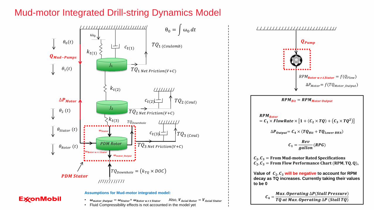
Mud-motor Integrated Drill-string Dynamics Model
θ0 = නω0 𝑑𝑡
𝑸𝑷𝒖𝒎𝒑
∆𝑃𝑀𝑜𝑡𝑜𝑟= 𝑓(𝑇𝑄𝑀𝑜𝑡𝑜𝑟_𝑂𝑢𝑡𝑝𝑢𝑡)
𝑅𝑃𝑀𝑹𝒐𝒕𝒐𝒓 𝒘.𝒓.𝒕.𝑺𝒕𝒂𝒕𝒐𝒓 = 𝑓(𝑄𝐹𝑙𝑜𝑤)
𝑹𝑷𝑴𝑩𝒊𝒕 = 𝑹𝑷𝑴𝑴𝒐𝒕𝒐𝒓 𝑶𝒖𝒕𝒑𝒖𝒕
𝑹𝑷𝑴𝑹𝒐𝒕𝒐𝒓
= 𝑪𝟏 × 𝑭𝒍𝒐𝒘𝑹𝒂𝒕𝒆 × 𝟏 + 𝑪𝟐 × 𝑻𝑸 + 𝑪𝟑 × 𝑻𝑸𝟐
∆𝑷𝑶𝒖𝒕𝒑𝒖𝒕= 𝑪𝟒 × 𝑻𝑸𝑩𝒊𝒕 + 𝑻𝑸𝑳𝒐𝒘𝒆𝒓 𝑩𝑯𝑨
𝑪𝟏 =𝑹𝒆𝒗
𝒈𝒂𝒍𝒍𝒐𝒏(𝑹𝑷𝑮)
𝑪𝟐, 𝑪𝟑 = 𝐅𝐫𝐨𝐦Mud-motor Rated Specifications𝑪𝟐, 𝑪𝟑 = 𝐅𝐫𝐨𝐦 𝐅𝐥𝐨𝐰 𝐏𝐞𝐫𝐟𝐨𝐫𝐦𝐚𝐧𝐜𝐞 𝐂𝐡𝐚𝐫𝐭 (𝐑𝐏𝐌,𝐓𝐐,𝐐),
Value of 𝑪𝟐, 𝑪𝟑 will be negative to account for RPM
decay as TQ increases. Currently taking their values
to be 0
𝑪𝟒 =)𝑴𝒂𝒙.𝑶𝒑𝒆𝒓𝒂𝒕𝒊𝒏𝒈 ∆𝑷(𝑺𝒕𝒂𝒍𝒍 𝑷𝒓𝒆𝒔𝒔𝒖𝒓𝒆
)𝑻𝑸 𝒂𝒕 𝑴𝒂𝒙.𝑶𝒑𝒆𝒓𝒂𝒕𝒊𝒏𝒈 ∆𝑷 (𝑺𝒕𝒂𝒍𝒍 𝑻𝑸
𝑐𝑡(1)𝑘𝑡(1)
𝑘𝑡(2)
𝜃1(𝑡)
𝜃2 (𝑡)
𝐽1
𝐽2
𝜃0(𝑡)
ω0
𝑇𝑄𝐷𝑜𝑤𝑛ℎ𝑜𝑙𝑒 = 𝑘𝑇𝑄 × 𝐷𝑂𝐶
𝑇𝑄1 (𝐶𝑜𝑢𝑙𝑜𝑚𝑏)
𝑇𝑄2 (𝐶𝑜𝑢𝑙)𝑐𝑡(2)
𝑇𝑄2 𝑁𝑒𝑡 𝐹𝑟𝑖𝑐𝑡𝑖𝑜𝑛(𝑉+𝐶)
𝑇𝑄1 𝑁𝑒𝑡 𝐹𝑟𝑖𝑐𝑡𝑖𝑜𝑛(𝑉+𝐶)
𝑸𝑴𝒖𝒅−𝑷𝒖𝒎𝒑𝒔
𝑃𝐷𝑀 𝑅𝑜𝑡𝑜𝑟
∆𝑷𝑴𝒐𝒕𝒐𝒓
𝜃𝑆𝑡𝑎𝑡𝑜𝑟 (𝑡)
𝑷𝑫𝑴 𝑺𝒕𝒂𝒕𝒐𝒓
𝑘𝑡(3)
𝑐𝑡(3)
𝑇𝑄3 𝑁𝑒𝑡 𝐹𝑟𝑖𝑐𝑡𝑖𝑜𝑛(𝑉+𝐶)
𝑇𝑄3 (𝐶𝑜𝑢𝑙)
𝝎𝑹𝒐𝒕𝒐𝒓 𝒘.𝒓.𝒕 𝑺𝒕𝒂𝒕𝒐𝒓
𝝎𝒎𝒐𝒕𝒐𝒓_𝑶𝒖𝒕𝒑𝒖𝒕
𝑇𝑄𝐷𝑜𝑤𝑛ℎ𝑜𝑙𝑒
𝝎𝑺𝒕𝒂𝒕𝒐𝒓
𝜃𝑅𝑜𝑡𝑜𝑟 (𝑡)
Assumptions for Mud-motor integrated model:
• 𝝎𝒎𝒐𝒕𝒐𝒓_𝑶𝒖𝒕𝒑𝒖𝒕 = 𝝎𝑺𝒕𝒂𝒕𝒐𝒓+ 𝝎𝑹𝒐𝒕𝒐𝒓 𝒘.𝒓.𝒕 𝑺𝒕𝒂𝒕𝒐𝒓 Also, 𝑽𝑨𝒙𝒊𝒂𝒍 𝑹𝒐𝒕𝒐𝒓 = 𝑽𝑨𝒙𝒊𝒂𝒍 𝑺𝒕𝒂𝒕𝒐𝒓• Fluid Compressibility effects is not accounted in the model yet

Drill-string Dynamics Simulator Features - Verified & Validated
• Number of Drill-string Elements (Segregation into Drill-pipes, HWDP, Collars & Downhole Mud-motor Elements)
• Flexibility to choose different Topdrive ROP & RPM Input function (Constant, Ramp or Step)
• Rock-strength (Numerically Stable solution for as high as 60000 Psi Rock Strength)
• Number of Bit-blades (Symmetrical or Asymmetrical Blade positioning)
• Drill-pipe, HWDP, Collar & Bit/Hole size elements flexibility
• Tripping In/Out of hole, Drilling & Back-reaming operations
• Torque & Drag sensitivity testing using Side-forces (Well-path inclination dependent)
• Tracking of Drilling Vs Tripping phase (Hole-depth Vs Bit Depth Position Tracker)
• Independent Rotary & Axial Motion (SO/PU operations)
• Pipe ID/OD & Tool joint accounting
• Inclusion & Exclusion capability of Noise effects while Drilling
• Selection flexibility for Open & Cased Hole Friction Factor
• Stribeck Friction effect (Accounting of Exponential Non-linear Static to Dynamic Coulomb Friction Transition)
• Net frictional force accounting for borehole friction (Coulomb + Viscous)
• Well-bore inclination Angle (Well trajectory)
• Mud-Pumps Flow Rate (to feed Mud-motor input RPM)
• Slide & Rotate mode of drilling with Mud-motor (Flexibility of placing Mud-motor at different positions in BHA)
• Pipe Rocking phenomenon in Slide mode of drilling with Mud-motor
• Motor Back-off Event testing capability in Slide Mode (with drilled depths having interbedded formations)
• Low Friction Stabilizer & Lubrication trials testing capability