a simulator for nano-manipulation of nano-particle …ijssst.info/vol-13/no-2/paper3.pdf · a...
TRANSCRIPT
AHMAD NAEBI et al: A SIMULATOR FOR NANO-MANIPULATION OF NANO-PARTICLE . . .
DOI 10.5013/IJSSST.a.13.02.03 ISSN: 1473-804x online, 1473-8031 print 11
A Simulator for Nano-manipulation of Nano-particle Using Atomic Force Microscopy in Mathematica Software
Ahmad Naebi Department of Electronic and Computer Engineering
Qazvin Branch, Islamic Azad University Qazvin, Iran
Moharam Habibnejad Korayem College of Mechanical Engineering
Iran University of Science and Technology Tehran, Iran
Somayeh Paki Khatibi Department of Mechatronic Engineering Ahar Branch, Islamic Azad University
Ahar, Iran [email protected]
Mahdi AbbasGholipour Department of Mechanical Engineering Bonab Branch, Islamic Azad University
Bonab, Iran [email protected]
Abstract — In this research, a virtual reality environment is designed to overcome the problem of lacking real time visual feedback in working with AFM (Atomic Force Microscopy) in a nano-environment. For this purpose, dynamic behavior of nano-manipulator and particles are modeled in fluid environment. Furthermore, nano-manipulation of the nano-particle and fluid forces on tip of AFM cantilevers has been modeled. Also, the model is improved for liquid environment. Using our proposed model, users are capable of tracking nano-manipulation in the liquid environment. This research aims to design a virtual reality in liquid environment such that users can perceive the liquid forces graphically. Finally, one is able to observe ultimate result of nano-manipulation graphically prior to real implementation and experiment be performed.
Keywords – Simulator, Nano–manipulation, Nano–particle, Atomic Force Microscopy (AFM), Mathematica Software, Simulation, Liquid Forces
I. INTRODUCTION
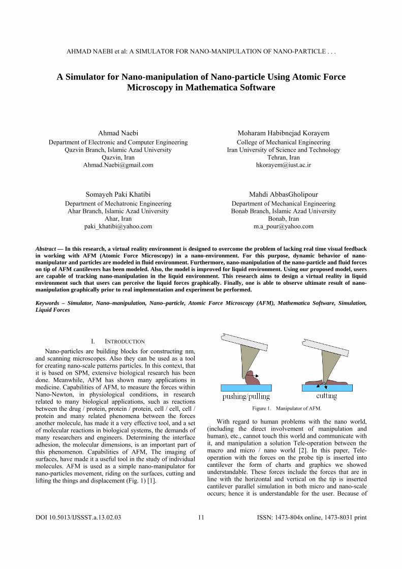
Nano-particles are building blocks for constructing nm, and scanning microscopes. Also they can be used as a tool for creating nano-scale patterns particles. In this context, that it is based on SPM, extensive biological research has been done. Meanwhile, AFM has shown many applications in medicine. Capabilities of AFM, to measure the forces within Nano-Newton, in physiological conditions, in research related to many biological applications, such as reactions between the drug / protein, protein / protein, cell / cell, cell / protein and many related phenomena between the forces another molecule, has made it a very effective tool, and a set of molecular reactions in biological systems, the demands of many researchers and engineers. Determining the interface adhesion, the molecular dimensions, is an important part of this phenomenon. Capabilities of AFM, The imaging of surfaces, have made it a useful tool in the study of individual molecules. AFM is used as a simple nano-manipulator for nano-particles movement, riding on the surfaces, cutting and lifting the things and displacement (Fig. 1) [1].
Figure 1. Manipulator of AFM.
With regard to human problems with the nano world, (including the direct involvement of manipulation and human), etc., cannot touch this world and communicate with it, and manipulation a solution Tele-operation between the macro and micro / nano world [2]. In this paper, Tele-operation with the forces on the probe tip is inserted into cantilever the form of charts and graphics we showed understandable. These forces include the forces that are in line with the horizontal and vertical on the tip is inserted cantilever parallel simulation in both micro and nano-scale occurs; hence it is understandable for the user. Because of

AHMAD NAEBI et al: A SIMULATOR FOR NANO-MANIPULATION OF NANO-PARTICLE . . .
DOI 10.5013/IJSSST.a.13.02.03 ISSN: 1473-804x online, 1473-8031 print 12
cantilever motion and atomic force microscope probe, the micro scale is visible in the water‘s molecules are not understood and is visible like typical liquid and also when motion of nano-scale conducting probe be. Water molecules are visible and the motion of water molecules which move against the forces of cantilever and probes are applied and the graphics can be seen at the nano-scale [3]. Also, their graphs equations are solved using dynamic fluid forces during motion are shown.
II. NANO-PARTICLE MANIPULATION MODEL
Indeed, the purpose of this study is to define the physical properties of nano-particles with radius RP, which absorbed by the probe of AFM in a liquid environment as driving is displaced. At first, Nano-manipulation particles to drive the probe head are placed in contact with the particles. Therefore, to ensure their contact with the desired conditions fertile, primary ZP0 in cantilever by the feedback system is established. The different 4 stages of the movement of particles according to nano-manipulation are presented in Fig. 2[4].
Figure 2. Nano-manipulation States in manipulation of nano-particle [4].
From A to B, the top of the tool in the Z axis moves automatically until it touches to substrate. This is clearly determined by bending of cantilever. Then, a predetermined stop position is back.
From B to C, tip of the tools along the substrate until the contact line is determined by cantilever rich moving and then stops. The deflection of cantilever can be determined with optical methods.
From C to D, with movement of tip of tool or substrate with a constant speed, the force exerted on the particle is beginning to be increased until it reaches to its critical value for movement of particle over substrate and after this moment the particle is transferred to the desired position.
From D to E is also displacement of the particle and returning back to its initial position.
III. DYNAMIC MODELING
In nano-manipulation, the cylindrical probe has been considered [5]. View of the forces, cantilever, probe contact force between the probe and particle also forces between cantilever and the probe are shown in Fig. 3 and 4. They are presented in form of two forces from two aspects.
Fy and Fz are horizontal and vertical components between the probes and cantilever and V shear force is between the cantilever and probe (Fig. 3) and also Fx and Fz are horizontal and vertical components between the probe and cantilever, and V the shear is a force between the cantilever and probe (Fig. 4) and the FT contact force is made between the probe and a magnifying glass.
FXY and FZ are forces applied on the particle from the probe, and ψ, φ are angel of applying probe force and angel of contacting tip of the probe and the particle respectively (Fig. 5).
Figure 3. AFM cantilever and probe bending along y-z axes during
pushing nano objects [5].
Figure 4. AFM cantilever and probe bending along x-z axes during
pushing nano objects.
Dynamic equations are developed based on the free body diagram (FOB) of pushing system, including AFM cantilever and probe, nano-particle and substrate. Fig. 6 presents FOB

AHMAD NAEBI et al: A SIMULATOR FOR NANO-MANIPULATION OF NANO-PARTICLE . . .
DOI 10.5013/IJSSST.a.13.02.03 ISSN: 1473-804x online, 1473-8031 print 13
of probe of AFM in contact with particle in one hand and with cantilever on the other hand.
Figure 5. Positioning of the nano particles by the AFM tip contact
pushing [6].
Figure 6. FOB of probe.
There are following equation as kinematic state for the cantilever variation:
zP=zafm+Hcos(θ)cos(α)+(RP-δS)+(Rt+RP- δt)cos(φ) xP=xafm-(Rt+RP- δt)sin(φ)-Hsin(α) (1) yP=yafm-(Rt+RP- δt)sin(φ)-Hsin(θ) In dynamical equations, movement is along with x, y and
z directions and the moment is determined by the Euler equations. The rates of
Tx , Ty and
Tz are considered with zero and
Px , Py and
Pz are obtained by differentiation act in (1) then we can calculate final rate of Fx, Fy and Fz by place variables as yp, xp, θ and α.
Σ yF
=m ya
FY - ( FDtop+FDbelow ) cos γ - Fy - V cos θ =m (2
....
PT yy ) (2)
Σ xF
=m xa
FX - ( FDtop+FDbelow ) sin γ - Fx - V cos α =m (2
....
PT xx ) (3)
Σ zF
=m za
FZ -(Fz+ FDrag + Fel + Fsq +Fhyd)-Vsinθ
-Vsinα=m (2
....
PT zz ) (4)
Σ PM
=IP(....
)
Mθ+Fz H sinθsinα-FY Hcosθ-Mα-Fx Hcosα=IP (....
) (5) Finally pushing force, FT, ψ can be calculated from the
following equations:
FXY = 22YX FF (6)
FT = 22ZXY FF (7)
ψ = tan-1 (Z
Y
F
F ) (8)
Friction and normal forces are defined for semi-static state base on the probe angle and force as follows:
ft =FT cos ζ
sin:
FF Ttipt
t
fs =FT cos ψ - FDP (9) sin
:FF T
subss
ft is sliding friction force on the probe tip and substrate
and fs is a friction on real contact area and vertical force in the model JKR as perpendicular on it.
So, frictional model for sliding and rolling is defined as:
FT >
cossin s
ssDP AF
(10)
FT >
cossin)cos(sin
.
st
ts
rrP
trsrDP
R
AARF
(11)
In above equations μ is friction ratio τ is shear stability
and A is contact area between particle and substrate. Critical FT is depended on particle moving angle ψ, probe
and particle contact angle φ, frictional constants, contact area and dragging applied force on particle in every time.
IV. LIQUID FORCES
Generally, applied forces on the surfaces of the things are divided in two shapes at fluid environment: molecule reaction forces and macro forces. They are applied in whole of the body, i.e., and whole of the cantilever.
AHMAD NAEBI et al: A SIMULATOR FOR NANO-MANIPULATION OF NANO-PARTICLE . . .
DOI 10.5013/IJSSST.a.13.02.03 ISSN: 1473-804x online, 1473-8031 print 14
A. Electrostatic Double Layer Force[7]
Electrostatic double layer force is the first force as molecule reaction state in dynamic problems. Mutual charge of the areas is a cause for its creation. Water is a high dielectric fluid. So, absorbing and defusing of the charge is great. Ions and the surfaces with electrical charges make an electrical layer. When an opposite area (charge with both sign) is closing to it, then ions will be increasing among of the areas and making a repulsing force. This force is decreased in high distances, strongly (Fig. 7).
There is a relation among of the potentials in closing time as follows: ψ (ξ= x) = ψ2, ψ (ξ= 0) =ψ1, Also the force rate is defined as follows: (To estimate of the potentials for a sample)
)12(])(2[2 2220 D
D
TSD
D
TSD
cpel
eeRF
Figure 7. Changes in potential distribution between two surfaces during
approaching each other, space between these two is filled with fluid.
B. Hydration Force
Hydration is another force in this environment. Under hydration effect on two areas, if you consider the fluid environment to be continuous, there is a force from 1 to 3 nano-Newton as a repulsive into the areas when the fluid diagonal is less than fluid molecules. In fact, this force is a kind of short range force with a little density of the salt less than 0.1M/Lit so that is negligible against compare to electrostatic force. In some of cases in smooth areas and low salty densities, this force decreases in high distances exponentially and repulsive energy rate is estimated as:
U=Ae(-x/λ
H) (13)
λH is Decay length and amplitude A is equal to 0.001-10
J/m3. This force has a more contribution in high densities in compare with electrostatic force.
C. Steric Force
Another force is Steric Force or a force in mean of atomic arrangement force in the space. This force is usually made by repulsive form among of two covered areas with polymer in a suitable solution. Polymer molecules under adhesive power into the area makes a repulsive force with entropy increasing as a result of hanging of the chains into the area when the molecules are getting close to each other. That follows:
L0= nl5/3Γ1/3 (14)
)15(])
2()
2[()( 4
3
0
49
023
L
x
x
LTKxf
B
D. Adhesion Force
Perhaps, adhesion force is one of the most important forces in nano views. This force is made as a result of probe contact with the sample and we need to enough energy for separation at this case. Due to more complexity in its adhesive power, there are a lot of studies done by different researchers. They often believe that it is a combine of electrostatic force, Vander valence, chemical bonds, acid and base. In this study, we have utilized these combinations as an adhesive energy in the area and used from Johnson-Kendall-Roberts theory in contact dynamic calculations.
Area adhesive energy among of nano-particles and the probe is supposed to be w=0.2J/m2, in JKR model. (a rational rate for the areas in fluidity state) [8,9].
That follows:
)16(24 oD
H
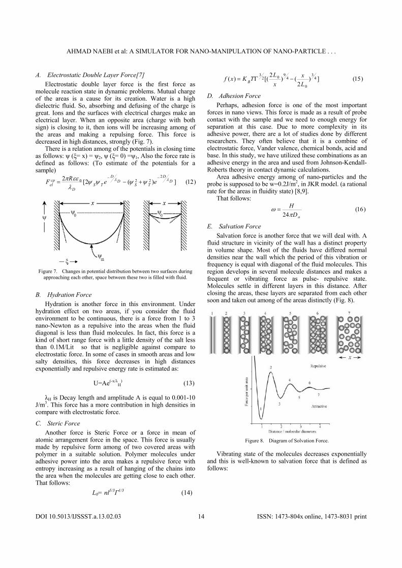
E. Salvation Force
Salvation force is another force that we will deal with. A fluid structure in vicinity of the wall has a distinct property in volume shape. Most of the fluids have differed normal densities near the wall which the period of this vibration or frequency is equal with diagonal of the fluid molecules. This region develops in several molecule distances and makes a frequent or vibrating force as pulse- repulsive state. Molecules settle in different layers in this distance. After closing the areas, these layers are separated from each other soon and taken out among of the areas distinctly (Fig. 8).
Figure 8. Diagram of Solvation Force.
Vibrating state of the molecules decreases exponentially and this is well-known to salvation force that is defined as follows:

AHMAD NAEBI et al: A SIMULATOR FOR NANO-MANIPULATION OF NANO-PARTICLE . . .
DOI 10.5013/IJSSST.a.13.02.03 ISSN: 1473-804x online, 1473-8031 print 15
)17()2cos()(
x
exfxf
F. Hydrophobic Force
Lastly, another force is related to Hydrophobic Force. In this condition escaped water areas are absorbed to each other strongly. This is water Hydrophobic Force and occurs on the surfaces with a contact angle more than 90 degrees. This event doesn't occur at all when one of the areas is related to the escaped ones and other one is adopted with water.
Irraelachilli [10] showed that reaction among of two areas in escaped water property is stronger than Vander valence force. Experimental results approved this absorption among of two areas in Mika with a cation layer in it. However, there are many studies done in this field but there is no obvious evident and calculative theory in practice. It seems that this force has a short term for distances in 2-6nm and a long term until 100nm distances.
G. Drag Force
After reviewing the forces in nano-space, we want to deal with two main forces in macro aspects and their contribution on dynamic relations afterward. The first force is a drag force which is as a result of fluid movement on cantilever areas. There are two kinds of drag by fluid movement:
1) Pushing drag in vertical areas on fluid flow. (it is negligible due to very low thickness of the
cantilever) 2) Frictional drag as a result of fluid movement on both
of sides (up and down sides) and tensile shear. There are different ways for estimation of the drag
coefficient. Many researchers have considered AFM cantilever as cylinder shape [11] and studied on drag force of cantilever form well. Fig. 9 shows a view from AFM cantilever, clearly.
Figure 9. AFM cantilever.
The dimensional and mechanical properties of cantilever and particle are as Table I and II.
TABLE I. THE AFM GEOMETRIC CONSTANTS
)( mL )( mw )( mt )( mH )(nmRt 225 24 1 12 20
TABLE II. THE AFM MECHANICAL PROPERTIES [12]
)(GPaE )(GPaG )/( 3mKg
169 0.27 66.54 2330
In recent modeling method, cantilever moves in horizontal path and parallel with substrate. Because of small and thin thickness of cantilever in compare to width and length and low Reynolds of the flow, drag coefficient rate is as same as drag coefficient in a rectangular cube. So, frictional drag inserts in two sides. Suppose that:
)18(
)Re
4.7log(Re
8
DD
DC
Drag force from the fluid is:
)19()(2
1 2 DLVCFDDrag
In fact, frictional drag force applied on up and down areas of the cantilever and we have focused on it extremely. Jump flow is considered as a flow with low Reynolds rate and a fluid with non-compressibility state. When the cantilever submerged in liquid, because of flow pass above and below the object (Fig. 10) viscous drag effects on both sides.
Figure 10. Flow pass above and below AFM cantilever [13].
In order to derive drag force, we must calculate the velocity profile. We investigate steady flows at low Reynolds number, restricting ourselves to incompressible flows [14, 15]. The equation of motion may be expressed in the form of :
)20(
up
Because of the thin thickness of cantilever (1 μm), we assume 1-Dimensional flow:
)21(1
2
2
2
2
y
u
x
p
y
u
x
p
Initial condition: y=0 → u=0 y=H → u=U Therefore:
)22())(2(2
1)(2
1)( 22 yHx
pU
Hy
x
pyu
The pressure gradient in unknown, assuming incompressible flow:
)23(
belowtoptotalQQQ
)24(,,2
1
0
H
topbelowudyQhUQ
)25(2
1)()( hUhHUQhHUQ
toptotal

AHMAD NAEBI et al: A SIMULATOR FOR NANO-MANIPULATION OF NANO-PARTICLE . . .
DOI 10.5013/IJSSST.a.13.02.03 ISSN: 1473-804x online, 1473-8031 print 16
)26()2
(63
)()25,24,23(32
2 hH
H
U
H
U
x
p
)27(x
u
)28()
2
()2
(63
2
32
2
H
H
x
pU
yh
HH
U
H
UWLF
TopD
Below the cantilever Assume
)29(0)(h
UWLF
x
pBelowD
These rates are applied in the model to detect the variations for the results.
H. Squeeze film
Another force is a force which is occurred under squeeze film effect condition. When the cantilever is closing into the area, squeeze film detects towards the width. Suppose that there is a parallel beam with the surface as 1/ LW and a gap with none of dimension as 1/ WHS is the Height, then flow equations will be in stock form under a thin layer and obtained force is:
)30()1
( 3
SVLF
S
It is applied in whole of the cantilever. Force of squeeze film loses its effect meet to distance increasing and just the drag force is appeared.
I. Surface Tension
Other force is Surface Tension. When the probe of AFM is submerged in liquid, in on point along the cantilever contact between liquid surface and cantilever happens. When the cantilever moves to push the particle, the liquid surface in contact with cantilever stretches and resists against movement. To overcome this effect, some works has to be done.
In this work, dw is proportionassl with increasing in surface area dA [16]. Introducing the proportionally constant γ we got:
)31(.dAdw
The constant γ is called surface tension and the force calculated as below:
)32(2 bDx
dWF
V. DYNAMIC MODELING ALGORITHM
Generally dynamic modeling algorithm is shown in Fig. 11, which shows a summary of the manipulation. (Overall algorithm without liquid) The overall process diagram of the nano-manipulation in broth medium in Fig. 12 is presented in details which are total force that enter on tip of cantilever from frictional , fluid and adhesion forces.
Figure 11. Algorithm of dynamic modeling, particle motion in the driving.
Figure 12. Flowchart dynamic modelling algorithm in pushing nano-
particle.
VI. VIRTUAL REALITY ENVIRONMENT
First of all a dialog box will be shown to user in first step of program running which enter number of particles to create the environment Then this graphical environment, is visible from two scales. The first scale is the micro, which is viewed from cantilever and probe of AFM with the liquid and can be seen in Fig. 13. The second is the nano-scale,

AHMAD NAEBI et al: A SIMULATOR FOR NANO-MANIPULATION OF NANO-PARTICLE . . .
DOI 10.5013/IJSSST.a.13.02.03 ISSN: 1473-804x online, 1473-8031 print 17
which nano-particles on their number and distribution of water molecules around them, you can see in Fig. 14.
Figure 13. A view of the cantilever, probes and water from micron-scale
Figure 14. A view of the water molecules and nanoparticles from
nanoscale.
Most visible events in manipulation, happen at the nano-scale, and from nano-scale are visible. Because micro-and nano-scale is more understandable, we choose a scale between these two, which indicates that when we are moving from nano to micron, molecules are disappeared (Fig. 15).
Figure 15. A view of the water molecules and nano-particles from both
nano/micro scale.
Before manipulation, at first the target atoms for manipulation should be chosen. Coordination of the destination is shown in Fig. 16. That must be chosen for manipulation. Probe Path from source until the nano-particles, is shown as line (Fig. 17).
Figure 16. Determination of the final coordinates by user.

AHMAD NAEBI et al: A SIMULATOR FOR NANO-MANIPULATION OF NANO-PARTICLE . . .
DOI 10.5013/IJSSST.a.13.02.03 ISSN: 1473-804x online, 1473-8031 print 18
Figure 17. The line indicates the probe moves from origin to near nano-
particles.
A. Moving Foward Nano-particles Steps
1) In nano-manipulation, cantilever moves nano-particle from its origin coordinates (defined by default) toward selected nano-particles which coordinate to transfer at a height of 88 microns. First, movement of probe and cantilever is done in air. When it reaches to the desired atom, motion along X and Y axis stops which you can see in Fig. 18 and 19 (Which is at the micron scale). At this point nothing happens on the nano-scale. (Fig. 14) Because of this, probe has not reached into the nano-particles or nano-definition environment for manipulation. Probe is located at an altitude of 88 micron, but the Nano is defined to 1000nm, 1000nm, 1000nm and nanotechnology events happens in this range.
2) Then cantilever and probes began to decrease the height, until enters the water and hit with substrate When cantilever (Fig. 20) and it encounters with level (Fig. 21).
Figure 18. Starting cantilever and probe movement, from origin to selected
nano-particles.
Figure 19. Cantilever and probe reaching into designated location, close to the selected nanoparticles(probe movement Starting, toward the substrate).
Figure 20. Entering cantilever into the water.

AHMAD NAEBI et al: A SIMULATOR FOR NANO-MANIPULATION OF NANO-PARTICLE . . .
DOI 10.5013/IJSSST.a.13.02.03 ISSN: 1473-804x online, 1473-8031 print 19
Figure 21. Starting cantilever and probe movement, from origin to selected
nano-particles.
From the moment that cantilever enters to water, the water forces influence on cantilever is shown in nano-scale, in Fig. 22, 23 and 24. Also probe and cantilever speed, during movement is constant speed.
The forces of the liquid to probe are entered to the tip of cantilever. The first hydration force, the force of compression is applied in hydration of water molecules around the probe surrounding them (Fig. 22) and the compression of the electrostatic forces will be created and gradually by approaching the layers to the electrostatic force increases it is shown in Fig. 23. Because of this the drag is significantly better than drag on cantilever vertical line to separate displays. (Fig. 24)
Figure 22. Hydration Force
Figure 23. The electrostatic force to hydration Force and the compression
force increases electrostatic force.
Figure 24. The drag force enters in a vertical line on cantilever.
B. Parking
In the next step, the probe will collide with the surface and at the height part of the probe to a certain height. The amount of rise in height has been calculated previously. Then the particle movement will be done by probing the nano-particles (Fig. 25 and 26).

AHMAD NAEBI et al: A SIMULATOR FOR NANO-MANIPULATION OF NANO-PARTICLE . . .
DOI 10.5013/IJSSST.a.13.02.03 ISSN: 1473-804x online, 1473-8031 print 20
Figure 25. Moving of probe to collide the tip of probe with Nano particle.
Figure 26. Start to move of nanoparticles with Probe.
C. Pushing
In this level we move the nano-particles, and take them to the destination. And the liquid forced into the cantilever will be imposed to the probe. As they will be invisible in micron scale. We illustrate them in micron scale (Fig. 27). Where the movement in the route is briefly described (Fig. 28).
Figure 27. The horizontal drag along the probe moves in the direction of
nano-particles.
Figure 28. Moving particles with the two forces along the X and Y angle
phe.
Figure 29. Hydration probe with water molecules.

AHMAD NAEBI et al: A SIMULATOR FOR NANO-MANIPULATION OF NANO-PARTICLE . . .
DOI 10.5013/IJSSST.a.13.02.03 ISSN: 1473-804x online, 1473-8031 print 21
D. Return
Return to its original location and nano-probe cantilever manipulation again for the next particle, begins when the probe separated from the nano-particles in Fig. 29. First, followed by electrostatic force, the squeeze film force on the surface is shown in Fig. 30. By approaching to the water level, gradually disappear. The return of the cantilever and probe in micro-scale can be seen in Fig. 31 and 32.
Figure 30. Creating and lossing from the electrostatic force.
Figure 31. Cantilever enter to air.
Figure 32. The levels of the rise of base level to a height of 88 microns.
The formation and loss of water molecules (generated from the loss of fluid forces) is done. (Reverse phase)
VII. THE ANALYSIS OF GRAPHS OF THE VIRTUAL AND
REALITY ENVIRONMENT
A. The level of the Step towards nano-particles and parking
1) Moving in air: In the following motion, cantilever and probe in the air,
moves in X and Y axis. And when moving, no force can be entered on cantilever and also we have no moves along the Z axis. Also the FT resultant force will be zero. We have Nano-particles trough the substrate and no sinking between nano-particle and probe, so we have no collision between the probe and nano-particles. Graphs of probe movement, along the two axes of X and Y, from the point of origin to near nano-particle is shown in Fig. 33.
Figure 33. Moving the probe from the source, close to the nano-particles
(the X axis right and Y axis, in air)

AHMAD NAEBI et al: A SIMULATOR FOR NANO-MANIPULATION OF NANO-PARTICLE . . .
DOI 10.5013/IJSSST.a.13.02.03 ISSN: 1473-804x online, 1473-8031 print 22
2) The resultant force, and forces the fluid acts on nano-manipulation, nano-particles in a liquid environment, the graphical interface:
The vertical line on the probe enters to water when the surface tension force into the cantilever then the surface tension force is destroyed consequently, drag and other forces are applied because the drag is high, and low amounts of other forces. This is presented in the diagram. At the collision moment, the force is increased enough which is demonstrated by probing the substrate (Fig. 34). And after the collision, the probe goes up to a certain height. After the collision, the forces before it enters the collision and the force along the Z axis, enters into the cantilever and entered into force on the X and Y axis is zero, with can be seen in the graph in Fig. 35.
Figure 34. The diagram of FT.
Figure 35. The diagram of the forces X and Y axis.
Electrostatic force, in the layers closer to each other, will increase. That is illustrated in the diagram (Fig. 36).
Figure 36. The diagram of electrostatic force, the moment the probe to
move the probe to reach the substrate.
Squeeze film force, from the surface, from the moment that cantilever enters to the water and its diagram is illustrated in Fig. 37.
Figure 37. The diagram of squeeze film force, the moment the probe to
move the probe to reach the substrate.
Drag force in the vertical direction of the force of surface tension enters into the Cantilever. The diagram shows in Fig. 38.
Figure 38. The diagram of drag force, just move the probe until the probe
reaches the substrate level.
B. Rushing
The nano-particles in the probe go down and the force increases As long as the force overcomes the resistance of the resistance forces and nano-particles will move. Fig. 39 shows the time that the nano-particles remained constant (increasing force as critical to the nano-particles) and then began to move (Fig. 39).

AHMAD NAEBI et al: A SIMULATOR FOR NANO-MANIPULATION OF NANO-PARTICLE . . .
DOI 10.5013/IJSSST.a.13.02.03 ISSN: 1473-804x online, 1473-8031 print 23
Figure 39. Start time of moving nano-particle (FT >sliding force).
Analysis of behavior of nano-particles and the probe tip can be briefly stated in Fig. 40. Also, the amount of applied force along the y axis along the x axis by cantilever amount of force exerted by cantilever is shown in Fig. 41 which illustrates that the applied force relative to the x axis and y axes is high.
Figure 40. The diagram of X, Y of AFM and Nano-particle in
Manipulation.
Figure 41. The diagram of y, x axes forces (from start applyin force to
nano-particle till end of manipulation).
The graphs in Fig. 42 present, the resultant cutting force, the sliding force and the time is rolling. As the sliding force occurs, the nano-particles start to slip. (Perhaps the reason is that the Rolling is happen. Probe contact with the nano-particles did not happen just because of the nano-particles is applied.)
Figure 42. Top)The diagram FT force Cross the diagram sliding force.
Down) The diagram FT force Cross the diagram rolling force.
Just drag force, in line with the angle on the horizontal axes x and y enter. Forces along the x axis and y axis of the

AHMAD NAEBI et al: A SIMULATOR FOR NANO-MANIPULATION OF NANO-PARTICLE . . .
DOI 10.5013/IJSSST.a.13.02.03 ISSN: 1473-804x online, 1473-8031 print 24
probe and through it enters cantilever. However, the z axis due to staying at a certain height, and the fluid forces, it is a constant force during nano-manipulation. The force diagram is shown in Fig. 43 (green curve, resultant forces, and yellow diagram, the axis z, and eliminating the brown curve x, and y-axis in the red graph shows the manipulation).
Figure 43. The diagram of y, x and z axes forces(from start applyin force to
nano-particle till end of manipulation).
Resultant drag force, the horizontal line is inserted on cantilever. The blue line diagram is shown in Fig. 44.
Figure 44. The diagram of other forces (from start applyin force to nano-
particle till end of manipulation).
C. Return
Graph squeeze film, electrostatic, drag, and hydration force is like parking, so that the diagram is the reverse.
VIII. CONCLUSION AND FUTURE WORKS
In this paper nano-manipulation of nano-particles in a liquid environment and the graphical interface has been presented. We demonstrated that our model gives a better understanding of fluid forces and nano-manipulation users.
Hence the user will be able to have a better communication with the micron and nano. And also the users do nano-manipulation, in virtual reality environment before to have a better vision in real nano-manipulation.
REFERENCES [1] D. Fotiadis, S. Scheuring, Sh. A. Muller, A. Engel, D. J. Muller,
"Imaging and Manipulation of Biological Structures with the AFM", Micron 33, pp 385-397, 2002.
[2] M. Sitti, “Teleoperated 2-D Micro/Nanomanipulation Using Atomic Force Microscope”. Ph. D. Dissertation, University of Tokyo, Tokyo, Japan, 1999.
[3] M.H.Korayem, A.Naebi, S.Esmaeilzadeha, A.M.Shahri, "Tele-operated Nano-manipulation in Liquid Environment with Atomic Force Microscopy", Proceedings of the 4th Asia International Symposium on Mechatronics (AISM 2010), ISBN: 978-981-08-7723-1.
[4] M. Sitti, H. Hashimoto, “Force Controlled pushing of nanoparticles: modeling and experiments,” IEEE/ASME Trans. on Mechatronics, Vol.5, pp.199-211, June 2000.
[5] Metin Sitti And Afshin Tafazzoli, “Dynamic Behavior And Simulation Of Nanoparticle Sliding During Nanoprobe-Based Positioning” , Proceedings Of IMECE 2004 ASME International Mechanical Engineering Congress Anaheim, CA, November 13-19, 2004.
[6] Metin Sitti and Afshin Tafazzoli, “Dynamic Modes of Nanoparticle Motion during Nanoprobe-Based Manipulation”, Dept. Of Mechanical Eng, Carnegie Mellon University, Pittsburgh, PA 15213, USA.
[7] D.Erts. Study of the nanoscale contacts with the help of combine TEM-AFM technique and heoretical MD-TM calculation. Department of Engineering, Physics, and Mathematics, Mid Sweden University. (2000).
[8] Sitti M, Hashimoto H (2003)Teleoperated Touch Feedback from the Surfaces at the Nanoscale: Modeling and Experiments, IEEE/ ASME Transactions on Mechatronics 8(1) March.
[9] Sitti M, Hashimoto H (2000) Force controlled pushing of nanoparticles: modeling and experiments. IEEE/ASME Trans on Mechatronics 5:199–211 June.
[10] J.N. Israelachvili, R. Pashley, Nature 300 (1982) 341.
[11] R.E. Jones, D.P. Hart, Force interactions between substrates and SPM cantilevers immersed in fluids, Elsevier science Vol.38, No. 355-361 (2005).
[12] M. H. Korayem, M. Zakeri, "Sensitivity Analysis of Nanoparticles Pushing Critical Conditions in 2-D Controlled Nanomanipulation Based on AFM", J. Adv Manuf Technol, DOI 10.1007/s00170-008-1519-0, 2008.
[13] Fluid Properties at Nano/Meso Scale: A Numerical Treatment P. Dyson, R. S. Ransing, P. M. Williams and P. R. Williams.
[14] Joseph H. Spurk · Nuri Aksel, "Fluid Mechanics", second edition.
[15] M.Midoux, "Mecanique et rheologie des fluides", en genie chimique.
[16] Hans-Jürgen Butt, Karlheinz Graf, Michael Kappl ," Physics and Chemistry of Interfaces",Wiley-VCH: Berlin, 2003