a simple, yet still “fool-resistant,” sequencer · paul wade w1ghz ©2002, 2003, 2016...
TRANSCRIPT

A simple, yet still “fool-resistant,” sequencer Revision b – 2016
Paul Wade W1GHZ ©2002, 2003, 2016
In 2002, I first described the “simple, yet still ‘fool-resistant,’ sequencer1.” It proved to be quite popular, with several hundred PC boards out there. As I built higher power transverters that needed more sophisticated switching, I developed the “Even more fool-resistant sequencer2” which includes conditional logic as well as sequencing, and opto-isolators for remote operation. However, this one is quite complex. Lately, I’ve been working on simple, low-cost transverters at modest power levels, aimed at rovers and new bands. For these rigs, a simple sequencer is adequate, so I resurrected the simple fool-resistant sequencer and added a few enhancements.
Figure 1 – Simple, yet still fool-resistant sequencer, Revision b
– Before describing the sequencer in detail, I will describe the enhancements added in Revision b. The original article about the earlier versions is available at www.w1ghz.org.
1. One request I had for the original was to power the coax relay on receive, rather than transmit, so that the preamp is only connected to the antenna when power is on. Revision b has a jumper to select whether the coax relay is powered on transmit or receive. The jumper must be present to select one direction or the other.
2. Switching for preamp power (+12V) is provided, for those who prefer to switch the preamp power off while transmitting. It can also be used to switch power to the receive side of the transverter. Switched +12V on transmit is also available.
3. Inhibit line to FT-817 inhibit pin – prevents it from transmitting until coax relay and amplifier are ready.
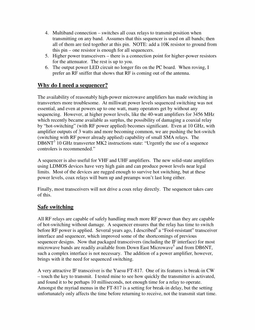
4. Multiband connection – switches all coax relays to transmit position when transmitting on any band. Assumes that this sequencer is used on all bands; then all of them are tied together at this pin. NOTE: add a 10K resistor to ground from this pin – one resistor is enough for all sequencers.
5. Higher power transceivers – there is a connection point for higher-power resistors for the attenuator. The rest is up to you.
6. The output power LED circuit no longer fits on the PC board. When roving, I prefer an RF sniffer that shows that RF is coming out of the antenna.
Why do I need a sequencer?
The availability of reasonably high-power microwave amplifiers has made switching in transverters more troublesome. At milliwatt power levels sequenced switching was not essential, and even at powers up to one watt, many operators get by without any sequencing. However, at higher power levels, like the 40-watt amplifiers for 3456 MHz which recently became available as surplus, the possibility of damaging a coaxial relay by “hot-switching” (with RF power applied) becomes significant. Even at 10 GHz, with amplifier outputs of 3 watts and more becoming common, we are pushing the hot-switch (switching with RF power already applied) capability of small SMA relays. The DB6NT3 10 GHz transverter MK2 instructions state: “Urgently the use of a sequence controlers is recommended.” A sequencer is also useful for VHF and UHF amplifiers. The new solid-state amplifiers using LDMOS devices have very high gain and can produce power levels near legal limits. Most of the devices are rugged enough to survive hot switching, but at these power levels, coax relays will burn up and preamps won’t last long either. Finally, most transceivers will not drive a coax relay directly. The sequencer takes care of this.
Safe switching
All RF relays are capable of safely handling much more RF power than they are capable of hot-switching without damage. A sequencer ensures that the relay has time to switch before RF power is applied. Several years ago, I described4 a “Fool-resistant” transceiver interface and sequencer, which improved some of the shortcomings of previous sequencer designs. Now that packaged transceivers (including the IF interface) for most microwave bands are readily available from Down East Microwave5 and from DB6NT, such a complex interface is not necessary. The addition of a power amplifier, however, brings with it the need for sequenced switching. A very attractive IF transceiver is the Yaesu FT-817. One of its features is break-in CW – touch the key to transmit. I tested mine to see how quickly the transmitter is activated, and found it to be perhaps 10 milliseconds, not enough time for a relay to operate. Amongst the myriad menus in the FT-817 is a setting for break-in delay, but the setting unfortunately only affects the time before returning to receive, not the transmit start time.
One alternative to a sequencer is to turn off the break-in feature and rely on manual switching. But how long will it be before you throw the switch with the key already closed, or start shouting before the mike button is depressed? Only a fool would say never! A while back, I wanted to integrate a Down East Microwave transverter with a surplus amplifier. Rather than tear apart a finished transverter to add the “fool-resistant” interface, I decided to make a small, simple, external sequencer which retains the fool-resistant functions: switch the relay before activating the transverter and amplifier, and make the switching as fail-safe as possible. One fail-safe feature is provided by RF sensing in addition to hard switching, so that even if the control cable fails (or is forgotten), the transverter will be switched safely. Since I prefer to run the PTT control signal up the IF coax cable, I added this capability also. The FT-817 and some other transceivers have an INHIBIT pin, which prevents the radio from transmitting. This latest Revision b sequencer will control the INHIBIT pin, preventing transceiver output until everything else is ready. This is one more fool-resistant feature.
Sequencer design
The schematic diagram of the sequencer, shown in Figure 2, is drawn to separate and label functional sections. At the top left is the IF input; the RF is passed through a small 4-dB attenuator to reduce the nominal 2.5 watt output of many portable transceivers to the 1-watt level needed by many of the packaged transverters. Down East Microwave Design Note 015 reports6 that transverters occasionally suffer damage to the receive mixer when driven with an IF level > 1 watt, so this attenuator reduces the danger of damage. Even if the attenuator is not needed, RF sensing is still possible for IF power levels > 100 milliwatts by connecting the IF input to C2. [Note: the FT-817 can be set to transmit at powers lower than 2.5 watts, but produces serious spurs on CW and SSB when run at lower powers. This has been documented by Leif, SM5BSZ (www.sm5bsz.com). Byron, N1EKV, found a fix but it requires serious disassembly to replace a component on the bottom of the PC board. A simpler solution is to always run the radio at 2.5 watts output.] There are three potential sources to activate the sequencer: RF, PTT hi, and PTT lo.
• The RF sensing circuit, between C2 and Q1, detects any transmit power from the IF transceiver and begins the switching sequence. The RF sensing may be omitted and components left out.
• PTT hi is the input for transceivers that supply a positive voltage on transmit.
• PTT lo is the input for transceivers that ground the control line on transmit. Normally, only one of these is used in any installation, but both PTT variations are common. The jumper is used to select whichever polarity is expected on the IF cable. If the control signal is on the IF coax cable, it is separated from the RF path by C1 and L1. My preference is to run the PTT control signal up the IF cable and have RF sensing as a

C2
2.2 pfR4
47K
C3
1000
C4
22µF
R5
8.2K
Q1
MPSA13
C6
0.1
R6
100K
Q2
NMOS: BS170, VN2222
D3
1N4148C7
0.1 uF
D4
5V Zener
Q3
2N3904
R9
22K
D5
1N4148
C9
47µF
Q5
NMOS: BS170, VN2222
NMOS
Q6
Q4
IRF510,IRFZ14
PowerPole
J1
L1
1µH
D7
LED
Jumper
PTT Hi
PTT Lo
C5
1000 pf
Q7
PMOS
R8
4.7K
R7
4.7K
R11
1K
R10
10K
Relay
Transverter
to AMP
AMP
+12V
GND
D8
1N4001
D6
1N4001
C8
0.1 D9
1N4001
C10
0.1
D1
1N5711
D2
1N5711
NMOS
Q8 D10
LED
Q9
PMOS
R12
1K
R13
10K
to PREAMPD11
1N4001
Jumper
Q10
NMOS: BS170, VN2222
FT-817 Inhibit
R1
22
22
R2
R3
10
R14
330 330
R15
330
R16
C1
1000
To_TransverterIF_input
D12
1N4148
MultiBand Option
RF detect
PTT Hi (+V to XMIT)
PTT Lo (GND to XMIT)
Hi
Lo
GND end of Coax Relay
Transverter - GND to XMIT
Amplifier - GND to XMIT
+12V TX
Switched
Unswitched Power Input
Timing
Switch
W1GHZ 2002
Simple, but still "Fool-Resistant" Sequencer
(Select switching on IF cable)
RED
IRF9Z34 (10 amps)
IRF9Z14 (5 amps)
BS170
VN2222
NOTE: pinout varies,
source is ground end
S
G
D
S
G
D
NOTE: put fuse in power cable
NOTE: heatsink > 2 amps
NOTE: put diode across relay coil
+12V RX
Switched
IRF9Z14 (5 amps)
S
G
D
NOTE: heatsink > 2 amps
CoaxTR Relay
RX active
TX active
BS170
VN2222
FT-817 - GND to Inhibit XMIT
4 dB Attenuator
Revision b 2016
(Relay closed on Receive)
(Relay closed on Transmit)
(Select Mode)
(To activate coax relays on all bands when transmitting, connect this pin of all sequencers together)
.

fail-safe, so that the transverter is switched anytime the IF rig is transmitting. RF sensing also allows the use of any spare IF rig, even a handy-talkie, in the event of a failure. Any of the three inputs will activate the switch transistor, Q3, which will immediately drive the relay driver, Q4, and turn off power to the preamp, switched by Q8 and Q9. After a delay time set by R9 and C9 (roughly ¼ second with the values shown), the switches for the transverter and amplifier are activated. To return to receive, all inputs cease and Q3 switches back to the receive state, turning off all outputs; diode D5 removes the delay in this direction so all outputs switch immediately. The immediate turnoff is another fail-safe – it resets the delay time if the PTT is “stuttered” – so the coax relay may chatter but no RF will be applied so it won’t be damaged. The transmit delay may be increased or decreased by changing the value of C9 – the delay is proportional to the capacitance. The three outputs are all FET switches to minimize size and power consumption, so there are no relays to fail. The whole sequencer should only draw a few milliamps, mostly for the LED indicators:
• The first output, marked RL on the board, is the relay driver, Q4, an NMOS power FET which grounds the low end of the coax relay, with the other end connected to +12 or +28 volts, whatever is required (the negative end of a +28 volt power supply would be grounded). The FET is capable of driving a hefty relay, but don’t forget to put a diode directly across the relay coil.
The coax relay may be activated on transmit (Tx) or on receive (Rx), depending on your preference. The direction is selected by the Jumper J3, but one or the other must be selected. A wire may be soldered in place of the jumper for a permanent connection
• The second output, marked X on the board, switches the transverter; a small power FET, Q5, pulls this output to ground. It is adequate to drive the small relays inside most transverters.
• The third output switches the power amplifier. Here we have two possibilities: the first, for amplifiers with a control input and internal switching, like those from DEMI, Q6 pulls the terminal marked A on the board to ground to activate the amplifier. The second, for amplifiers without any switching, like those from DL2AM7, require that the 12 volt supply to the amplifier be switched (we don’t want to leave the amplifier drawing power continuously). In this case, Q6 drives a PMOS power FET, Q7, which switches the voltage at the terminal marked AMP+ on the board with little voltage drop. The schematic lists an inexpensive FET good for 5 amps or so, and a heftier one good for 10 amps or more. If the amplifier draws more than a couple of amps, a heat sink is needed on Q7. This output could also be used to provide power to the transmit side of a transverter.
• The fourth, new, output , marked P+ on the board, provides +12V power to the Preamp, or to the receive side of a transverter, or both. The power is switched by a

PMOS power FET, Q9. No heatsink should be required at normal preamp power levels.
• The fifth, new, output, marked INH on the board, connects to the inhibit pin of the FT-817 and other transceivers, to prevent the transceiver from transmitting until coax relay and amplifier are ready.
Also new is the Multiband connection, marked MB on the board, used to connect multiple sequencers together in a multiband station so that all coax relays switch to the transmit position when any band is transmitting. NOTE: this pin requires a 22K resistor to ground, but only one resistor is needed for multiple sequencers connected together. Finally, there are two LED outputs. D7 lights on transmit, while D10 lights on receive, when the preamp is powered. Colors are optional. A clever ham could find a way to use a single bicolor LED.
Construction The circuit fits on a small printed circuit board. I included an Anderson PowerPole8 connector for the power input in the layout, so that the sequencer can be mounted on the panel as the power connector for the complete rig. The PowerPole can be mounted on either side of the board, depending on how you are mounting the board. The final fail-safe is the idiot diode, D9, to protect against reversed polarity – it will blow the fuse, so make sure there is a fuse in the power lead! The layout and connection diagram for the board is shown in Figure 3. Component locations are also marked pretty clearly by the silk-screen pattern on the top of the board. A photograph of a completed sequencer is shown in Figure 1. Construction is straightforward with common thru-hole components, and assembly goes pretty quickly. The LEDs are shown mounted on the board, but you’ll probably want them mounted to the box for visibility, probably with an additional LED to show that the power is on. My station sort of evolved into using red for power, green for transmit, and yellow or blue for other things, but you might choose different colors. Assembly order isn’t critical. I usually start with the resistors in order (R1, R2, etc.), then capacitors, followed by diodes, then transistors and the remainder. Soldering and lead trimming is in groups so there aren’t too many leads in the way. All the components are on the top side, so soldering is on the bottom except for the PowerPoles. The boards are soldermasked to help prevent solder bridges causing unwanted shorts. I tried to use cheap, common components so I could use a sequencer in each transceiver without pain – if you buy everything from Digi-Key9, total cost including the PC board should be under $20. None of the part values is critical, so you should be able to find some of them in the junk box. The parts list in Figure 6 includes Digi-Key part numbers, plus some alternative suggestions. One caution: the BS170 FETs in the parts list have a
different pinout than some of the alternative parts, so check carefully before installing
alternates.

Figure 3 – Connection diagram for Sequencer, Revision b
Since the schematic is organized into functional sections, you may leave out the components for any unneeded functions. Since the parts are cheap, I usually include them all, since it is easier to change a few connections than to modify the board later.
Errata Errata is a fancy way of saying that I made some mistakes in the Revision b PC layout that need to be fixed with a knife and soldering iron. The changes are shown in the bottom view of the layout, Figure 4, and a photo of the changes on the bottom of a board, Figure 5.
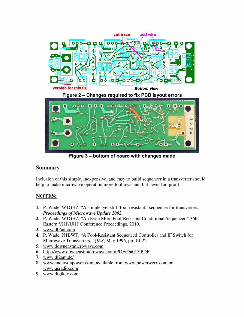
Figure 2 – Changes required to fix PCB layout errors
Figure 3 – bottom of board with changes made
Summary Inclusion of this simple, inexpensive, and easy to build sequencer in a transverter should help to make microwave operation more fool resistant, but never foolproof.
NOTES: 1. P. Wade, W1GHZ, “A simple, yet still ‘fool-resistant,’ sequencer for transverters,”
Proceedings of Microwave Update 2002. 2. P. Wade, W1GHZ, “An Even More Fool-Resistant Conditional Sequencer,” 36th
Eastern VHF/UHF Conference Proceedings, 2010. 3. www.db6nt.com
4. P. Wade, N1BWT, “A Fool-Resistant Sequenced Controller and IF Switch for Microwave Transverters,” QEX, May 1996, pp. 14-22.
5. www.downeastmicrowave.com
6. http://www.downeastmicrowave.com/PDF/Dn015.PDF
7. www.dl2am.de/ 8. www.andersonpower.com; available from www.powerwerx.com or
www.qsradio.com 9. www.digikey.com
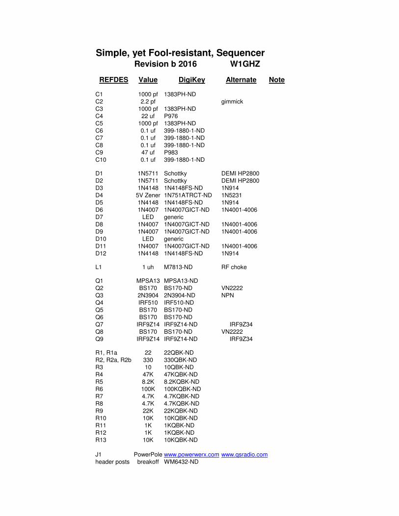
Simple, yet Fool-resistant, SequencerRevision b 2016 W1GHZ
REFDES Value DigiKey Alternate Note
C1 1000 pf 1383PH-ND
C2 2.2 pf gimmick
C3 1000 pf 1383PH-ND
C4 22 uf P976
C5 1000 pf 1383PH-ND
C6 0.1 uf 399-1880-1-ND
C7 0.1 uf 399-1880-1-ND
C8 0.1 uf 399-1880-1-ND
C9 47 uf P983
C10 0.1 uf 399-1880-1-ND
D1 1N5711 Schottky DEMI HP2800
D2 1N5711 Schottky DEMI HP2800
D3 1N4148 1N4148FS-ND 1N914
D4 5V Zener 1N751ATRCT-ND 1N5231
D5 1N4148 1N4148FS-ND 1N914
D6 1N4007 1N4007GICT-ND 1N4001-4006
D7 LED generic
D8 1N4007 1N4007GICT-ND 1N4001-4006
D9 1N4007 1N4007GICT-ND 1N4001-4006
D10 LED generic
D11 1N4007 1N4007GICT-ND 1N4001-4006
D12 1N4148 1N4148FS-ND 1N914
L1 1 uh M7813-ND RF choke
Q1 MPSA13 MPSA13-ND
Q2 BS170 BS170-ND VN2222
Q3 2N3904 2N3904-ND NPN
Q4 IRF510 IRF510-ND
Q5 BS170 BS170-ND
Q6 BS170 BS170-ND
Q7 IRF9Z14 IRF9Z14-ND IRF9Z34
Q8 BS170 BS170-ND VN2222
Q9 IRF9Z14 IRF9Z14-ND IRF9Z34
R1, R1a 22 22QBK-ND
R2, R2a, R2b 330 330QBK-ND
R3 10 10QBK-ND
R4 47K 47KQBK-ND
R5 8.2K 8.2KQBK-ND
R6 100K 100KQBK-ND
R7 4.7K 4.7KQBK-ND
R8 4.7K 4.7KQBK-ND
R9 22K 22KQBK-ND
R10 10K 10KQBK-ND
R11 1K 1KQBK-ND
R12 1K 1KQBK-ND
R13 10K 10KQBK-ND
J1 PowerPole www.powerwerx.com www.qsradio.com
header posts breakoff WM6432-ND