a shape memory alloy-magnetorheological fluid core bracing …
TRANSCRIPT

CSCE Annual Conference
Growing with youth – Croître avec les Jeunes
Laval (Greater Montreal)
June 12 - 15, 2019
A SHAPE MEMORY ALLOY-MAGNETORHEOLOGICAL FLUID CORE
BRACING SYSTEM FOR CIVIL ENGINEERING APPLICATIONS: A
FEASIBILITY STUDY
Shahin Zareie. Graduate Research Assistant, EME 3204, School of Engineering, The University of British Columbia, Kelowna, BC, Canada V1V 1V7. [email protected]
M. Shahria Alam Associate Professor, EME 4225, School of Engineering, The University of British Columbia, Kelowna, BC, Canada V1V 1V7 [email protected]
Rudolf J. Seethaler Associate Professor, EME 4225, School of Engineering, The University of British Columbia, Kelowna, BC, Canada V1V 1V7 [email protected]
Abolghassem Zabihollah Associate Professor, School of Science and Engineering, Sharif University of Technology, International Campus [email protected] Abstract: The stability of civil infrastructures is one of the main challenges for structural designers, users, and decision makers at the government level. To keep the stability and functionality of the structures against moderate and strong loads, extensive studies have been conducted to develop supplemental structural control systems, particularly bracing system, with the energy dissipation ability. For instance, bracing systems fitted with friction dampers, and viscous fluids are mounted in structural frames to provide the structural integrity against possible damage. These kinds of bracing systems are passive devices. Furthermore, most of the existing active and semi-active supplemental system integrated with bracing systems are not able to return the system to the initial position (the re-entering ability). Therefore, new hybrid smart structural elements integrated with smart materials, shape memory alloy and magnetorheological fluid, have been developed to improve the structural stability and enhance the re-entering ability of structural elements in infrastructures. In this study, a hybrid smart bracing system is introduced to partially dissipate the amount of energy and add the re-entering ability to the structure. The new hybrid smart bracing element consists of the shape memory alloy (SMA) wires combined with magnetorheological (MR) fluid damper in its core. This system is able to keep the integrity and enhance the dynamic behavior of civil infrastructure during seismic events.

Simple implementation, easy istallation, low operation and maintenance costs, energy dissipation capacity, the re-entering ability, and fast response are counted as the advantages of the present hybrid smart bracing system.
Keywords: stability, civil infrastructure, shape memory alloy, magnetorheological fluid, bracing system, energy
dissipation capacity, the re-entering ability
1 INTRODUCTION
During the past decades, the seismic activities put civil infrastructures at risk, injured and lost thousands of lives due to the poor design and/or the lack of strength. Furthermore, falire of civil infra structures causes decreasing the economic growth and polluting the environment. To keep civil infrastructures healthy and stable, the structural control system should be designed and embedded in civil infrastructures. Nowadays, a wide range of those systems has been installed, including active, semi-active, and passive systems. The Isolation systems (Esteki 2014), the tuned mass damper (Soto and Adeli 2013; Mirzai, Zahrai, and Bozorgi 2017), as a passive structural control systems, active tendon system (Loh, Lin, and Chung 1999), as active structural control systems, and the semi-active tuned mass damper (Hrovat, Barak, and Rabins 1983), semi-active viscous fluid damper(M D Symans et al. 1994), semi-active stiffness control (Michael D Symans and Constantinou 1999) as semi-active structural control systems are some of the examples.
Most of the conventional structural control systems suffer from some disadvantages, including, energy requirement for activation, complicated operational procedure and lack of adaptively for different loading conditions. Recently, rapid advancements in smart materials and structures provided us new features in development of structural control systems with loading adaptively while requiring a minimum amount of energy. In the past years, the magnetorheological fluid(MRF) and the shape memory alloy(SMA) have been attracting the attention for structural control systems (Aryan and Ghassemieh 2017; Zareie et al. 2017b; Zareie et al. 2017a).
Magnetorheological fluid (MRF) is a type of a smart fluid with the ability to change the viscosity under applied the magnetic field. The MRF is made of very small ferromagnetic particles suspended by a fluid, such as the oil. Another component in the MRF is Stabilizer. The stabilizer keeps the thermal properties of the MRF and prevents the settling down of the particles. Nowadays, MRF-based systems are used extensively in many engineering applications such as aerospace, automotive, and particularly civil engineering(Zabihollah et al. 2017; Sarrafan et al. 2011; Naji, Zabihollah, and Behzad 2016). MRF-based isolation systems (Oliveira et al. 2017; Wang et al. 2018; Hapipi et al. 2018; Gu et al. 2017; Cantera et al. 2017), MRF-based damper (Lakhani and Soni 2017; Yoshioka, Ramallo, and Spencer Jr 2002; Iwata et al. 2002; Zamani et al. 2018; Fu et al. 2017) are two commons applications of MRF-based systems in civil engineering. Those systems improve the dynamic behavior of the civil infrastructures and keep their stability, by increasing the energy absorption ability and the equivalent viscous damping coefficient of civil infrastructures. They can adjust themselves for various loading conditions while require relatively small amount of energy.
However, the MRF-based bracing systems are not able to move back to the initial position. To provide the moving back option to MRF systems, two solutions could be considered, including push (pull) back by applying the external excitation or combined with other smart system and materials, such as shape memory alloy (SMA) with recovery ability, as the optimized solution. SMA is a type of alloy, which is able to return to the pre-defined shape after experiencing large deformation due to the superelasticity (SE) or the shape memory effect (SME) (Song, Ma, and Li 2006). In the SE, the recovery occurs with removing the external excitations, and in the SME, the residual strain (deformation) eliminates by applying heat. The contrast between SE and SME in civil engineering application shows that SE is much in demand rather than SME. It is mainly linked to the simplicity of the use and no need for the external heat. SMA-based applications are used solely, such as SMA-based damper, SMA-based bars or integrated to other applications, like isolation system, to enhance the dynamic behavior of civil infrastructures (Zhang and Zhu 2007; Savi,
Pacheco, and Braga 2002; Sun and Rajapakse 2003; Tu et al. 2011; Jennings and van de Lindt 2014). In spite of those advantages in SE of SMA-based applications, the functionality of SMA, including recovery ability and energy dissipation capacity are the only function of applied loads. On other hands, the outputs of the systems are not controllable.
In order to develop a smart system with controllable energy absorption capacity and recovering ability, a combination of the SMA and MRF is suggested. In this study, the SMA-MRF bracing system, as the structural control systems is designed to implement in buildings. To find the effect of the suggested smart system, it has been integrated into the idealized frame. The time-history displacement, the maximum displacement, and the root-mean-square displacement have been obtained to illustrate the improvement in structural response.
2 THE MRF-SMA CORE BRACING SYSTEM
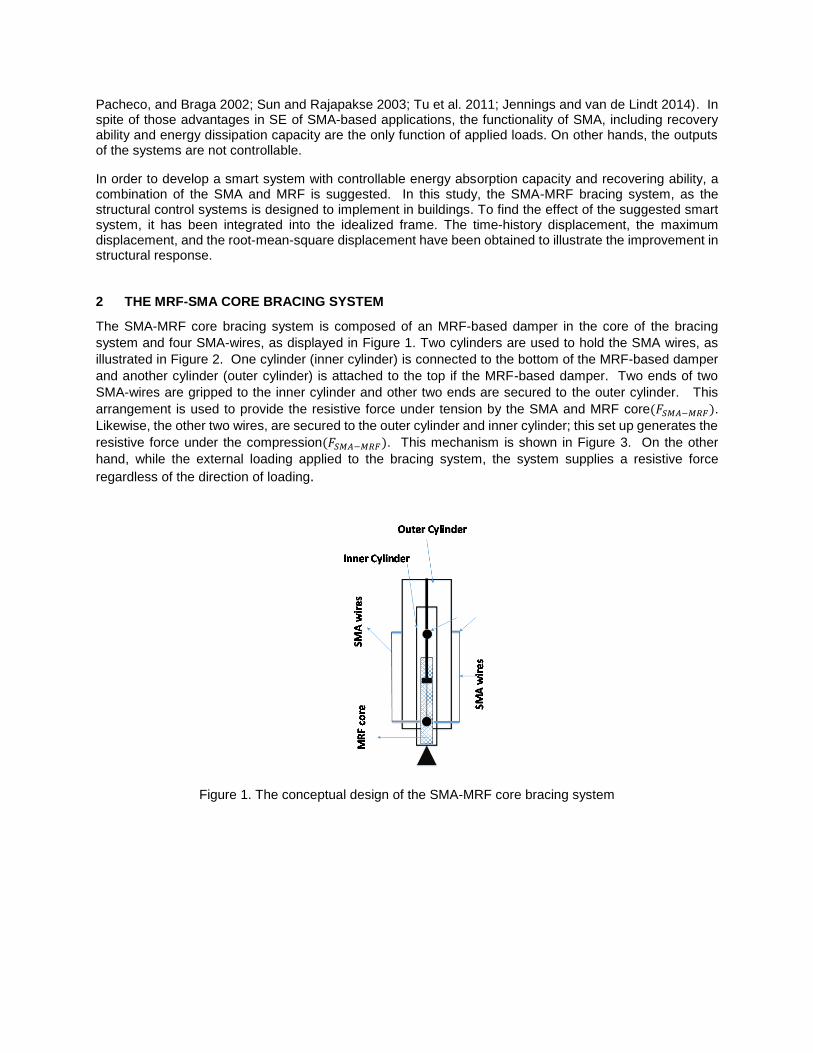
The SMA-MRF core bracing system is composed of an MRF-based damper in the core of the bracing
system and four SMA-wires, as displayed in Figure 1. Two cylinders are used to hold the SMA wires, as
illustrated in Figure 2. One cylinder (inner cylinder) is connected to the bottom of the MRF-based damper
and another cylinder (outer cylinder) is attached to the top if the MRF-based damper. Two ends of two
SMA-wires are gripped to the inner cylinder and other two ends are secured to the outer cylinder. This
arrangement is used to provide the resistive force under tension by the SMA and MRF core(𝐹𝑆𝑀𝐴−𝑀𝑅𝐹).
Likewise, the other two wires, are secured to the outer cylinder and inner cylinder; this set up generates the
resistive force under the compression(𝐹𝑆𝑀𝐴−𝑀𝑅𝐹). This mechanism is shown in Figure 3. On the other
hand, while the external loading applied to the bracing system, the system supplies a resistive force
regardless of the direction of loading.
Figure 1. The conceptual design of the SMA-MRF core bracing system
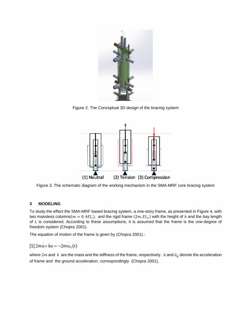
Figure 2. The Conceptual 3D design of the bracing system
Figure 3. The schematic diagram of the working mechanism in the SMA-MRF core bracing system
3 MODELING
To study the effect the SMA-MRF based bracing system, a one-story frame, as presented in Figure 4, with
two massless columns(𝑚 = 0, 4𝐸𝐼𝑐), and the rigid frame (2𝑚, 𝐸𝐼∞) with the height of ℎ and the bay length
of 𝐿 is considered. According to these assumptions, it is assumed that the frame is the one-degree of
freedom system (Chopra 2001).
The equation of motion of the frame is given by (Chopra 2001).:
[1].. ..
2 2 ( )gmu ku mu t
where 2𝑚 and 𝑘 are the mass and the stiffness of the frame, respectively . �̈� and �̈�𝑔 denote the acceleration
of frame and the ground acceleration, correspondingly (Chopra 2001).

h
2EIc 2EIc
2mEIb= u
ug
L
Figure 4. The one-story model of the frame
By inserting the SMA-MRF core bracing system into the frame, as shown in Figure 5, Eq.1 is modified to:
[2].. ..
2 2 ( )g SMA MRFmu ku mu t F
where 𝐹𝑆𝑀𝐴−𝑀𝑅𝐹 is the resistive force of the SMA-MRF based bracing system.
With respect to the mechanism of the bracing system, 𝐹𝑆𝑀𝐴−𝑀𝑅𝐹 is expressed by:
[3] SMA MRF MRF SMAF F F
where 𝐹𝑀𝑅𝐹 and 𝐹𝑆𝑀𝐴are the force supplied by the SMA wires and the MRF core, respectively.
Smart bracing system
Figure 5. The fame with the x-bracing system
3.1 The SMA modeling
The first main components of the bracing system are the SMA wires. The resistive force supplied
by SMA wires is given by:
[4] SMAF A
where 𝜎 and 𝐴 denote the stress in SMA wires and the cross-section, respectively.
The stress is given by (Zuo et al. 2009):
[5] ( ) ( )T
E

where 𝐸, 𝜀, and 𝜀𝑇 represent the Young modulus, the strain, and phase transformation strain,
correspondingly.
The Young modulus is defined by:
[6] ( )A M A
E E E E
where 𝜁 is the phase transformation strain. The terms 𝐸𝐴 and 𝐸𝑀 denote Young modulus in the
Austenite phase and the Martensite phase.
3.2 The MRF core modeling
The core of the bracing system is the MRF-based damper. The force of damper is a function of
the applied magnetic field and basic viscosity of the MRF in the damper. This force is given by
(Unsal 2006; Yang et al. 2002):
[7]MRFF F F
where 𝐹𝜏 is the uncontrollable force, as a result of a friction force and a plastic viscous force. 𝐹𝜇
is the controllable force and its magnitude is a function of the varied viscosity of MRF.
4 EARTHQUAKES
In order to apply the ground motions (GMs) to the introduced frame, three GMs including
Christchurch, Imperial Valley, and Parkfield are chosen and scaled to 1:2. The properties of the
GMs are given in Table 1.
Acceleration time history of Christchurch, Parkfield, and Imperial Valley are shown in Figure 6,
Figure 7, and Figure 8, respectively.
Table 1 Selective ground motions and characteristics in three tectonic environments(Pieper 2018)
Earthquake Year Site Mw R(km) Vs30(m/s)
Christchurch,NZ 2011 Resthhaven 6.2 5 141
Imperial Valley, USA 1979 E.C.A.-3
6.5
13 163
Parkfield, USA 2004 P.F.Z.-1 6 3 178

Figure 6. Acceleration time history of the Christchurch earthquake at the Resthhaven station
Figure 7. Acceleration time history of Parkfield earthquake at the P.F.Z.-1 station
-0.4
-0.2
0
0.2
0.4
0 10 20 30 40 50
Acc
elar
atio
n(g
)
Time(s)
Christchurch
-0.6
-0.4
-0.2
0
0.2
0.4
0.6
0.8
0 5 10 15 20 25
Acc
ela
rati
on
(g)
Time(s)
Parkfield

Figure 8. Acceleration time history of the Imperial Valley earthquake at the E.C.A.-3 station remarkable
5 NUMERICAL MODELING
In order to model and analyze the frame equipped with the SMA-MRF bracing system, the OpenSees (the
Open System for Earthquake Engineering Simulation), is used. A frame with the height of 3657 mm and
the bay length of 7314mm is considered. The weight of the frame is about 100kN. The Young modulus and
the moment of inertia of each column are about 206.84 kN/mm2 and 133.19×106 mm4, respectively.
5.1 The MRF damper
Table 2. The properties of the MRF damper
PHYSICAL PROPERTIES Value
Stroke (mm) 74
Extended Length (mm) 248
Body Diameter(mm) 42.1
Shaft Diameter(mm) 10
Tensile Strength(N) 8896 max
Damper Forces (N) ,Peak to Peak, 5 cm/sec @ 1 A >2447
Damper Forces N) ,Peak to Peak, 20 cm/sec @ 0 A <667
Operating Temperature(°C) 560
Input Current, Continuous for 30 seconds(A) 1 max
Input Current, Intermittent(A) 2 max
Input Voltage(V) 12 V
-0.2
-0.1
0
0.1
0.2
0.3
0 10 20 30 40
Acc
elar
atio
n(g
)
Time(s)
Imperial Valley
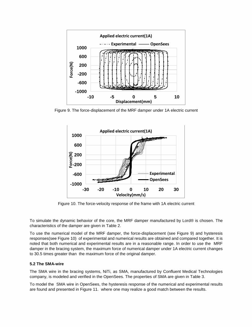
Figure 9. The force-displacement of the MRF damper under 1A electric current
Figure 10. The force-velocity response of the frame with 1A electric current
To simulate the dynamic behavior of the core, the MRF damper manufactured by Lord® is chosen. The
characteristics of the damper are given in Table 2.
To use the numerical model of the MRF damper, the force-displacement (see Figure 9) and hysteresis
responses(see Figure 10) of experimental and numerical results are obtained and compared together. It is
noted that both numerical and experimental results are in a reasonable range. In order to use the MRF
damper in the bracing system, the maximum force of numerical damper under 1A electric current changes
to 30.5 times greater than the maximum force of the original damper.
5.2 The SMA-wire
The SMA wire in the bracing systems, NiTi, as SMA, manufactured by Confluent Medical Technologies
company, is modeled and verified in the OpenSees. The properties of SMA are given in Table 3.
To model the SMA wire in OpenSees, the hysteresis response of the numerical and experimental results
are found and presented in Figure 11. where one may realize a good match between the results.
-1000
-600
-200
200
600
1000
-10 -5 0 5 10
Forc
e(N
)
Displacement(mm)
Applied electric current(1A)
Experimental OpenSees
-1000
-600
-200
200
600
1000
-30 -20 -10 0 10 20 30
Forc
e(N
)
Velocity(mm/s)
Applied electric current(1A)
Experimental
OpenSees

The SMA wire in the bracing system has the length of 1635.72 mm. The area of the SMA wires are
computed by:
[8]max( )
( )2
MRFwire
ms
FcofA
where the 𝑐𝑜𝑓, max(𝐹𝑀𝑅𝐹), and 𝜎𝑚𝑠 are 3, 25KN, and 500 MPa, respectively.
Table 3. The specifications of the SMA
PROPERTIES Value
Melting point (oC) 1310
Density (g/cm3) 6.5
Electrical resistivity (μohm-cm) 82
Coefficient of Thermal Expansion(\oC) 11 x 10-6
Modulus of Elasticity(GPa) 41
Ultimate Tensile Strength(MPa) ≥1070
Total Elongation ≥10%
Figure 11. the Hysteresis response of the frame of the SMA specimen
6 RESULTS
The dynamic behavior of the introduced frame without structural control system under three scaled GMs
are investigated and shown in Figure 12. It is noted that the maximum displacement under Christchurch
Parkfield and Imperial Valley are about 37mm, 48mm, and 16mm, respectively.
To study the effect of the structural control system on the structural behavior of the frame, the time-history
analysis of the frame under the Imperial Valley GM is presented in Figure 13. It is observed that the control
system reduces the displacement sharply contrast to the frame without a structural control system. It is
mainly due to the effect of stiffness of the SMA and the structural damping effect of the MRF-core of the
suggested system.
0
100
200
300
400
500
600
0.00% 1.00% 2.00% 3.00% 4.00%
Stre
ss(M
Pa)
Strain
Hystresis response
Experimental
OpenSees

Figure 14 presents the maximum displacement of the frame under the Imperial Valley, the Christchurch
and Parkfield GMs. By inserting the SMA-MRF (0A) into buildings, the peak displacement drops about
59%, 10%, and 50%, respectively. By energizing the SMA-MRF (1A), it decreases by about 6 %, 30% and
62% under the same GMs, compared to the inactive structural control system. The contrast between the
two states of the suggested systems, reveals by setting the variable viscosity of the MRF core, the maximum
displacement of the frame.
The other studied parameter is the root-mean-square (RMS) displacement of the frame under GMs. A
contrast of the RMS displacements of the frame is illustrated in Figure 15. It is found that the RMS values
for the frame are approximately 3.06 mm, 2.43 mm, and 1.6mm under the Christchurch, the Parkfield, and
Imperial Valley GMs. It decreases to 1.01 mm, 1.76 mm and 0.38 mm with a frame with SMA-MRF (0A).
By implementing the SMA-MRF(1A) into the frame, the RMS displacement significantly decreases and
reach to 0.68 mm, 1.08 mm, and 0.14 mm subjected to same GMs.
The structural dynamic analysis of the frame proves the remarkable enhancement in the frame’s
response obtained with the SMA-MRF bracing systems, compared with frame without the bracing system
Figure 12. The displacement of the frame without the bracing system
Figure 13. The displacement of the frame with and without bracing system

Figure 14. The maximum displacement pf the frame under simulated GMs
Figure 15. The RMS displacement pf the frame under simulated GMs
.
7 CONCLUSION
In this study, the conceptual design of the SMA-MRF based bracing system is presented to take advantage of the SMA-based system and the MRF-based system and overcome the disadvantages found in each component. The proposed system works under tension and compression loading. The suggested system is installed in the simplified frame and subjected to the three simulated earthquakes. The main outcomes of the research are as follows:
1. The maximum and the RMS displacement have been remarkably reduced by the frame equipped with the SMA-MRF-based bracing system.
2. The contrast between active (0A) and inactive (1A) of the SMA-MRF-based system, the effect of the active structural control system is much rather than the inactive system.
ACKNOWLEDGMENTS
This research received funding from the Green Construction Research and Training Center (GCRTC). The authors wish to thank the University of British Columbia, Okanagan campus for the technical support. The
0
20
40
60
Christchurch Parkfield Imperial Valley
Dis
pla
cem
ent(
mm
)
Ground Motions
The maximum dispalcement
No Bracing system SMA-MRF0A SMA-MRF1A
0
1
2
3
4
Christchurch Parkfield Imperial
Dis
pla
cem
ent(
mm
)
Ground Motions
The RMS displacement
No Bracing system SMA-MRF0A SMA-MRF1A

authors also wish to thank Mr. Kyle Charles as a research engineer and ex-manager lab for his valuable help in experimental tests at the applied laboratory for advanced materials and structures at the University of British Columbia-Okanagan Campus.
The data provided by Mr. Chris Pieper, MASc, P.Eng is also much appreciated.
REFERENCES
Aryan, Hadi, and Mehdi Ghassemieh. 2017. “A Superelastic Protective Technique for Mitigating the Effects of Vertical and Horizontal Seismic Excitations on Highway Bridges.” Journal of Intelligent Material Systems and Structures 28 (12). SAGE Publications Sage UK: London, England: 1533–52.
Cantera, M Asun, Majid Behrooz, Ronald F Gibson, and Faramarz Gordaninejad. 2017. “Modeling of Magneto-Mechanical Response of Magnetorheological Elastomers (MRE) and MRE-Based Systems: A Review.” Smart Materials and Structures 26 (2). IOP Publishing: 23001.
Chopra, Anil K. 2001. Dynamics of Structures: Theory and Applications to Earthquake Engineering. Prentice-Hall.
Esteki, Kambiz. 2014. “Developing New Analytical and Numerical Models for Mr Fluid Dampers and Their Application to Seismic Design of Buildings.” The Department of Building, Civil, and Environmental Engineering,Concordia University.
Fu, Weiqing, Chunwei Zhang, Li Sun, Mohsen Askari, Bijan Samali, Kwok L Chung, and Pezhman Sharafi. 2017. “Experimental Investigation of a Base Isolation System Incorporating MR Dampers with the High-Order Single Step Control Algorithm.” Applied Sciences 7 (4). Multidisciplinary Digital Publishing Institute: 344.
Gu, Xiaoyu, Yang Yu, Jianchun Li, and Yancheng Li. 2017. “Semi-Active Control of Magnetorheological Elastomer Base Isolation System Utilising Learning-Based Inverse Model.” Journal of Sound and Vibration 406. Elsevier: 346–62.
Hapipi, Norhiwani Mohd, Saiful Amri Mazlan, Muntaz Hana Ahmad Khairi, and Norzilawati Mohamad. 2018. “The Damping Properties of Plate-Like Magnetorheological Elastomer.” In Key Engineering Materials, 772:56–60.
Hrovat, Davorin, Pinhas Barak, and Michael Rabins. 1983. “Semi-Active versus Passive or Active Tuned Mass Dampers for Structural Control.” Journal of Engineering Mechanics 109 (3). American Society of Civil Engineers: 691–705.
Iwata, Norio, Katsuhiko Hata, Hiroshi Sodeyama, Katsuaki Sunakoda, Hideo Fujitani, Takeshi Hiwatashi, Yoichi Shiozaki, and Satsuya Soda. 2002. “Application of MR Damper to Base-Isolated Structures.” In Smart Structures and Materials 2002: Smart Systems for Bridges, Structures, and Highways, 4696:352–63.
Jennings, Elaina, and John W van de Lindt. 2014. “Numerical Retrofit Study of Light-Frame Wood Buildings Using Shape Memory Alloy Devices as Seismic Response Modification Devices.” Journal of Structural Engineering 140 (7). American Society of Civil Engineers: 4014041.
Lakhani, Megha T, and Devesh P Soni. 2017. “Comparative Study of Smart Base-Isolation Using Fuzzy Control and Neural Network.” Procedia Engineering 173. Elsevier: 1825–32.
Loh, Chin-Hsiung, Pay-Yang Lin, and Nan-Hau Chung. 1999. “Experimental Verification of Building Control Using Active Bracing System.” Earthquake Engineering & Structural Dynamics 28 (10). Wiley Online Library: 1099–1119.
Mirzai, N., S.M. Zahrai, and F. Bozorgi. 2017. “Proposing Optimum Parameters of TMDs Using GSA and PSO Algorithms for Drift Reduction and Uniformity.” Structural Engineering and Mechanics 63 (2). TECHNO-PRESS PO BOX 33, YUSEONG, DAEJEON 305-600, SOUTH KOREA: 147–60.
Naji, Jalil, Abolghassem Zabihollah, and Mehdi Behzad. 2016. “Layerwise Theory in Modeling of Magnetorheological Laminated Beams and Identification of Magnetorheological Fluid.” Mechanics Research Communications 77. Elsevier: 50–59.
Oliveira, Fernando, Miguel Ayala Botto, Paulo Morais, and Afzal Suleman. 2017. “Semi-Active Structural Vibration Control of Base-Isolated Buildings Using Magnetorheological Dampers.” Journal of Low
Frequency Noise, Vibration and Active Control. SAGE Publications Sage UK: London, England, 1461348417725959.
Pieper, Christopher Gregory. 2018. “Seismic Analysis and Design of Hybrid Concrete Timber Structures with 2015 National Building Code of Canada.” University of British Columbia.
Sarrafan, Atabak, Seiyed Hamid Zareh, Amir Ali Khayyat, and Abolghassem Zabihollah. 2011. “Performance of an Offshore Platform with MR Dampers Subjected to Wave.” In Mechatronics (ICM), 2011 IEEE International Conference On, 242–47.
Savi, Marcelo A, Pedro M C L Pacheco, and Arthur M B Braga. 2002. “Chaos in a Shape Memory Two-Bar Truss.” International Journal of Non-Linear Mechanics 37 (8). Elsevier: 1387–95.
Song, Gangbing, N Ma, and H-N Li. 2006. “Applications of Shape Memory Alloys in Civil Structures.” Engineering Structures 28 (9). Elsevier: 1266–74.
Soto, Mariantonieta Gutierrez, and Hojjat Adeli. 2013. “Tuned Mass Dampers.” Archives of Computational Methods in Engineering 20 (4). Springer: 419–31.
Sun, Shuangshuang, and R K N D Rajapakse. 2003. “Dynamic Response of a Frame with SMA Bracing.” Proc. SPIE. doi:10.1117/12.484201.
Symans, M D, M C Constantinou, D P Taylor, and K D Garnjost. 1994. “Semi-Active Fluid Viscous Dampers for Seismic Response Control.” In First World Conference on Structural Control, 3–12.
Symans, Michael D, and Michael C Constantinou. 1999. “Semi-Active Control Systems for Seismic Protection of Structures: A State-of-the-Art Review.” Engineering Structures 21 (6). Elsevier: 469–87.
Tu, J W, J Liu, W Qu, Q Zhou, H B Cheng, and X D Cheng. 2011. “Design and Fabrication of 500-KN Large-Scale MR Damper.” Journal of Intelligent Material Systems and Structures. Sage Publications, 1045389X11399942.
Unsal, Memet. 2006. “Semi-Active Vibration Control of a Parallel Platform Mechanism Using Magnetorheological Damping.” University of Florida.
Wang, Qi, Xufeng Dong, Luyu Li, and Jinping Ou. 2018. “Mechanical Modeling for Magnetorheological Elastomer Isolators Based on Constitutive Equations and Electromagnetic Analysis.” Smart Materials and Structures 27 (6). IOP Publishing: 65017.
Yang, G, B F Spencer Jr, J D Carlson, and M K Sain. 2002. “Large-Scale MR Fluid Dampers: Modeling and Dynamic Performance Considerations.” Engineering Structures 24 (3). Elsevier: 309–23.
Yoshioka, H, J C Ramallo, and B F Spencer Jr. 2002. “‘Smart’ Base Isolation Strategies Employing Magnetorheological Dampers.” Journal of Engineering Mechanics 128 (5). American Society of Civil Engineers: 540–51.
Zabihollah, Abolghassem, Ali Selk Ghafari, Ali Yadegari, and Delara Rashidi. 2017. “Effects of MR-Fluid on Low-Velocity Impact Response of MR-Laminated Beams.” In AIP Conference Proceedings, 1858:40004.
Zamani, Abbas-Ali, Saeed Tavakoli, Sadegh Etedali, and Jafar Sadeghi. 2018. “Adaptive Fractional Order Fuzzy Proportional--Integral--Derivative Control of Smart Base-Isolated Structures Equipped with Magnetorheological Dampers.” Journal of Intelligent Material Systems and Structures 29 (5). SAGE Publications Sage UK: London, England: 830–44.
Zareie, Shahin, Nadia Mirzai, M. Shahria Alam, and Rudulf. J. Seethlaer. 2017a. “A Dynamic Analysis of a Novel Shape Memory Alloy-Based Bracing System.” In CSCE 2017. Vancouver, Canada.
———. 2017b. “An Introduction and Modeling of Novel Shape Memory Alloy-Based Bracing.” In CSCE 2017. Vancouver, Canada.
Zhang, Yunfeng, and Songye Zhu. 2007. “A Shape Memory Alloy-Based Reusable Hysteretic Damper for Seismic Hazard Mitigation.” Smart Materials and Structures 16 (5). IOP Publishing: 1603.
Zuo, Xiao-Bao, Ai-Qun Li, Wei Sun, and Xiang-Hua Sun. 2009. “Optimal Design of Shape Memory Alloy Damper for Cable Vibration Control.” Journal of Vibration and Control 15 (6). SAGE Publications: 897–921.