a seakeeping analysis method for an air-lifted vessel
TRANSCRIPT

ARTICLE IN PRESS
Ocean Engineering ] (]]]]) ]]]–]]]
Contents lists available at ScienceDirect
Ocean Engineering
0029-80
doi:10.1
� Corr
E-m
Pleasj.oce
journal homepage: www.elsevier.com/locate/oceaneng
A seakeeping analysis method for an air-lifted vessel
Nan Xie, D. Vassalos, A. Jasionowski, P. Sayer �
Department of Naval Architecture and Marine Engineering, Universities of Glasgow and Strathclyde, Henry Dyer Building, 100 Montrose Street, Glasgow G4 0LZ, UK
a r t i c l e i n f o
Article history:
Received 14 October 2007
Accepted 12 June 2008
Keywords:
Seakeeping
Frequency domain
Air-lifted vessel
Numerical prediction
18/$ - see front matter & 2008 Elsevier Ltd. A
016/j.oceaneng.2008.06.011
esponding author. Tel.: +44141548 3302; fax
ail address: [email protected] (P. Sayer).
e cite this article as: Xie, N., et al., Aaneng.2008.06.011
a b s t r a c t
A seakeeping analysis in the frequency domain is presented to predict the motion response of an air-
lifted vessel (ALV) in waves. The ALV is supported by pressurised air in two separate cushion chambers;
the pressure variation in the cushions has a significant effect on the motions of the vessel. The adiabatic
gas law is used to couple cushion pressure and the free-surface elevation of water inside the chamber.
Attention is focused on the waves generated by the pressure, and a method is presented to compute the
corresponding free-surface elevation. New numerical schemes are proposed for calculating the three-
dimensional free-surface elevation for the four wave numbers. Numerical results of the free-surface
elevation, escape area, escape volume and motion responses of the ALV are provided.
& 2008 Elsevier Ltd. All rights reserved.
1. Introduction
The innovative design of an air-lifted vessel (ALV) utilises thecushioning and lubricating properties of air to generate an efficienthigh-speed marine vehicle. An energy saving of up to 25% is possiblecompared to conventional high-speed mono-hulls or catamarans,based on model experiments by Allenstrom et al. (2001, 2003).
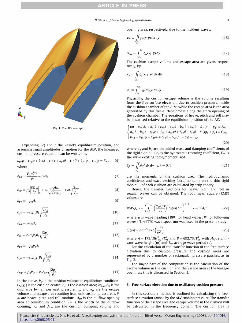
The selected ALV is a skirtless SES catamaran. There are twodemi-hulls, each of which contain an air cushion (see Fig. 1). Thedesign feature of the ALV is similar, in some sense, to that of anSES catamaran. There are two demi-hulls, each of which containsair cushions. A forward planing surface ahead of the step createssome limited dynamic lift. The step and the forward planingsurface also create the forward ceiling of the air cushion chamber,the step being located in a plane close to horizontal (no part of thestep is to ventilate before the other). The bow section is slender inorder to reduce displacement forces in a seaway, and the bowincorporate a voluminous part above a built-in chine/spray rail toreduce water deflection and reserve buoyancy in pitching motion.The side keels of varying height extend from just ahead of thestep to the transom. The height of the keels is adjusted to theobserved/expected shape of the air cushion. The only purpose ofthe side keels is to fence in the air cushion. There are spray rails onthe outside of the side keels, at a height partly to deflect the waterwithout wetting the rails on the upper sides. The cushion ceiling isat a height to avoid being hit by waves when the vessel is moving.The ceiling aft end slopes to deflect passing waves. A flap orenclosure arrangement in line with the sloped portion of theceiling is positioned to ‘fence’ the air cushion chamber in the rearpart and to create dynamic lift and motion damping. The air
ll rights reserved.
: +44141552 2879.
seakeeping analysis metho
cushion concept of the present ALV is patented (EFFISES Project,2001–2004). More details about the ALV concept can be found inAllenstrom et al. (2001).
In the ‘on-cushion’ mode, the vessel is mainly supported by thedifference between the ambient atmospheric pressure and that inthe plenum chamber. The pressure of the air captured in thechamber undergoes a pressure variation, and thus waves aregenerated on the free-surface. The dynamic response of the ALV inturn causes a reaction on the craft through the captured air, whichgenerates further variation of the air pressure. The motions affectpassenger and crew comfort as well as the performance ofelectronic components and machinery on board. In the presentpaper, a method is presented for the numerical prediction of theseakeeping performance of the ALV; this is similar to that for asurface-effect ship (SES), previously studied by other researchers,including Doctors (1976), Chen (1977), Kim and Tsakonas (1981),Kaplan et al. (1981), and Faltinsen (2005).
As the ALV is supported by pressurised air in two separatecushion chambers, the behaviour of the craft in waves is mainlydue to the pressure variation in the cushion chambers. Theadiabatic gas law is used to couple cushion pressure and the free-surface elevation inside the chambers. Computations of thecorresponding wave patterns are presented. Efficient and effectivenumerical schemes are proposed for calculating the three-dimensional free-surface elevation for the four wave numbers.Numerical results are also presented for the free-surface elevation,air cushion escape area and escape volume, and for the motion ofthe vessel in irregular waves.
2. Equations of motion of the ALV
A right-handed coordinate system oxyz is adopted with theplane z ¼ 0 in the undisturbed free-surface and z positive
d for an air-lifted vessel. Ocean Engineering (2008), doi:10.1016/

ARTICLE IN PRESS
Nomenclature
a length of a rectangular pressure patchai,j i, j ¼ 3, 4, 5, added mass for pitch, heave and rollA parameter of wave spectraAc cushion areaAL escape areaAL0 outflow opening area at equilibrium conditionALW cushion opening area due to incident waveb beam of a rectangular pressure patchbi,j i, j ¼ 3, 4, 5, damping for pitch, heave and rollB parameter of wave spectrabpi i ¼ 3, 5 coefficients for pressure and motion coupling
equationbpp coefficient for pressure and motion coupling equationBT width of outflow openingcn flow coefficientci,j i, j ¼ 3, 4, 5, hydrostatic restoring coefficients for
pitch, heave and rollcpi i ¼ 3, 5 coefficients for pressure and motion coupling
equationcpp coefficient for pressure and motion coupling equationE1 exponential integralfm m ¼ 1, 2, y, 8, functionFn length Froude number of a pressure patchFH hydrodynamic force/moment vectorFR hydrostatic force/moment vectorFP force/moment vector due to cushion pressureFW wave exciting force/moment vectorFwj j ¼ 3, 4, 5, wave exciting force/momentsFwp right-hand side term in the pressure and motion
coupling equationg acceleration due to gravitygm functionH1/3 significant wave heightIjj j ¼ 4, 5, craft mass inertia moment for roll and pitchJim i ¼ 0, 1, y, 6, m ¼ 1, 2, y, 8, terms in the wave
elevation for a rectangular pressure patchki i ¼ 0, 1, 2, 3, 4, wave numbersL craft lengthm indexM mass/inertia matrix
p cushion pressurepa atmospheric pressurepi pressure in cushion chambersp0 pressure in cushion chamber at equilibrium conditionq craft motion responsesqka amplitudes of motion responseQin inflow rateQout outflow rateRMS root mean square of the motion responsesSjk j, k ¼ 0, 1, moments of cushion areasm m ¼ 1, 2, y, 8, variables for wave elevation of
rectangular pressure patchSB wave spectrumT01 average wave periodu variable of functionsU craft speedV cushion volumevp escape volumevw cushion pumping volume due to incident wave~vp non-dimensional escape volumex, y, z coordinatesxc, yc centre of cushion areaz heaveZ height of cushion ceilinga escape area~a non-dimensional areaap escape area due to cushion pressureg ratio of specific heats for gas, Euler’s constant; also a
parameter in the wave elevation integralsf roll motion of the craftm wave headingy pitch motion; also a general angleyc cut-off angler densityra atmospheric air densityr0 density of air at equilibrium conditionrw water densitys encounter frequencyt reduced frequencyBp free-surface elevation due to cushion pressureBw incident wave elevationc a general function
N. Xie et al. / Ocean Engineering ] (]]]]) ]]]–]]]2
upwards. The origin is located at C.G. of the vessel. Frequencydomain analysis method will be used in the present study. Theequation of motions of the ALV can be expressed as
½M�½ €q� ¼ ½FH� þ ½FR� þ ½FP� þ ½FW�, (1)
where q is the motion vector of the vessel, M is the mass/inertiamatrix, FH is the hydrodynamic force/moment, FR is the hydro-static force/moment, FP is the force/moment due to the cushionpressure, and FW is the wave exciting force/moment.
The adiabatic gas law and continuity equation for the air ineach chamber are used to determine the cushion pressure in theport and starboard chambers:
pi þ pa þ p0;i
rgi¼ constant;
Vidri
dtþ ri
dVi
dt¼ raQ in;i � raQout;i;
8>>><>>>:
(2)
where the subscripts i( ¼ 1, 2) denote the port and starboardcushions, respectively; henceforth, for clarity this subscript will beomitted unless specifically required; p0 and r0 are cushion
Please cite this article as: Xie, N., et al., A seakeeping analysis methj.oceaneng.2008.06.011
pressure and air density at equilibrium operating condition; pa
and ra are atmospheric pressure and air density; Qin and Qout arethe inflow and out flow rate; V is the cushion volume, determinedby vessel motion attitude, incident wave and cushion pressure:
V ¼
ZZAc
½Zðx; yÞ � Bpðx; yÞ � Bwðx; yÞ�dx dy (3)
where Z is the cushion ceiling height, Bw and Bp are incident waveand free-surface elevation due to cushion pressure, respectively.The outflow rate can be expressed as
Qout ¼ cnAL
ffiffiffiffiffiffiffiffiffiffiffiffiffiffiffiffiffiffiffiffi2ðpþ p0Þ
ra
s(4)
where cnð� 0:620:8Þ is the flow coefficient and AL is the air escapearea of the flow opening at the cushion stern boundary:
AL ¼
Z yb
ya
½ZðxT; yÞ � BpðxT; yÞ � BwðxT; yÞ�dy (5)
where xT is the longitudinal coordinate of cushion stern aperture.
od for an air-lifted vessel. Ocean Engineering (2008), doi:10.1016/
ARTICLE IN PRESS
Fig. 1. The ALV concept.
N. Xie et al. / Ocean Engineering ] (]]]]) ]]]–]]] 3
Expanding (2) about the vessel’s equilibrium position, andassuming small amplitudes of motion for the ALV, the linearisedcushion pressure equation can be written as
bpp _pþ cpppþ bp3 _zþ cp3zþ bp5_yþ cp5yþ bp4
_fþ cp4f ¼ Fwp (6)
where
bpp ¼V0r1þg
0
gp0
� r0vp (7)
cpp ¼ ra
qQ in
qp
��������0
þ cnraAL0ffiffiffiffiffiffiffiffiffiffiffiffiffi2p0ra
p � cna
ffiffiffiffiffiffiffiffi2p0
ra
s(8)
bp3 ¼ �r0Ac (9)
cp3 ¼ �cnraBT
ffiffiffiffiffiffiffiffi2p0
ra
s(10)
bp5 ¼ r0xcAc (11)
cp5 ¼ cnraxcBT
ffiffiffiffiffiffiffiffi2p0
ra
s(12)
bp4 ¼ �r0ycAc (13)
cp4 ¼ �cnraycBT
ffiffiffiffiffiffiffiffi2p0
ra
s(14)
Fwp ¼ r0_vw þ cnALw
ffiffiffiffiffiffiffiffi2p0
ra
s(15)
In the above, V0 is the cushion volume at equilibrium condition;(xc, yc) is the cushion centre; Ac is the cushion area; qQ in=qp is thedischarge by fan per unit pressure; vp and ap are the escapevolume and escape area resulting from unit cushion pressure; z, y,f are heave, pitch and roll motions; AL0 is the outflow openingarea at equilibrium condition; BT is the width of the outflowopening; vw and ALw are the cushion pumping volume and
Please cite this article as: Xie, N., et al., A seakeeping analysis methoj.oceaneng.2008.06.011
opening area, respectively, due to the incident waves:
vw ¼
ZZAc
Bwðx; yÞdx dy (16)
ALw ¼
Z yb
ya
BwðxT; yÞdy (17)
The cushion escape volume and escape area are given, respec-tively, by
vp ¼
ZZAC
Bpðx; y;sÞdx dy (18)
ap ¼
Z yb
ya
BpðxT; y;sÞdy (19)
Physically, the cushion escape volume is the volume resultingfrom the free-surface elevation, due to cushion pressure, insidethe cushion chamber of the ALV; while the escape area is the areagenerated by this free-surface profile along the stern opening ofthe cushion chamber. The equations of heave, pitch and roll maybe linearised relative to the equilibrium position of the ALV:
ðmþ a33Þ€z3 þ b33 _zþ c33zþ a35€yþ b35
_yþ c35y� S00ðp1 þ p2Þ ¼ Fw3;
a53 €zþ b53 _zþ c53zþ ðI55 þ a55Þ€yþ b55
_yþ c55yþ S10ðp1 þ p2Þ ¼ Fw5;
ðI44 þ a44Þ€fþ b44
_fþ c44f� S01ðp1 � p2Þ ¼ Fw4;
8>><>>:
(20)
where aij and bij are the added mass and damping coefficients ofthe rigid side-hull, cij is the hydrostatic restoring coefficient, Fwj isthe wave exciting force/moment, and
Sjk ¼
ZZAc
xjyk dx dy j; k ¼ 0;1 (21)
are the moments of the cushion area. The hydrodynamiccoefficients and wave exciting force/moments on the thin rigidside-hull of each cushion are calculated by strip theory.
Hence, the transfer functions for heave, pitch and roll inregular waves can be obtained. The root mean square (RMS)values are
RMSkðmÞ ¼Z 1
0
qkaðmÞBa
� �2
SBðoÞdo !1=2
k ¼ 3;4;5, (22)
where m is wave heading (1801 for head waves; 01 for followingwaves). The ITTC wave spectrum was used in the present study:
SBðoÞ ¼ Ao�5 exp�B
o4
� �(23)
where A ¼ 173:18H21=3=T4
01 and B ¼ 692:73=T401 with H1/3 signifi-
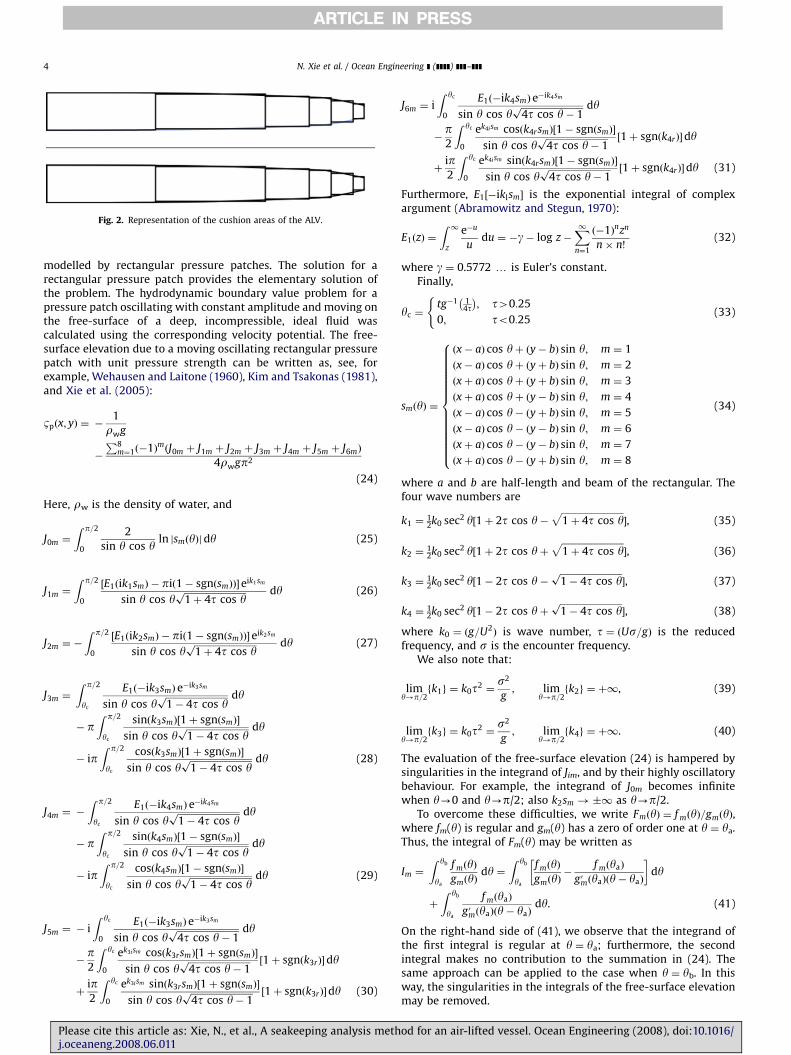
cant wave height (m) and T01 average wave period (s).For the calculation of the transfer function of the free-surface
elevation due to cushion pressure, the cushion areas arerepresented by a number of rectangular pressure patches, as inFig. 2.
The major part of the computation is the calculation of theescape volume in the cushion and the escape area at the leakageopenings; this is discussed in Section 3.
3. Free-surface elevation due to oscillatory cushion pressure
In this section, a method is outlined for calculating the free-surface elevation caused by the ALV cushion pressure. The transferfunction of the escape area and escape volume in the cushion willbe calculated in the frequency domain. The cushion area is
d for an air-lifted vessel. Ocean Engineering (2008), doi:10.1016/
ARTICLE IN PRESS
Fig. 2. Representation of the cushion areas of the ALV.
N. Xie et al. / Ocean Engineering ] (]]]]) ]]]–]]]4
modelled by rectangular pressure patches. The solution for arectangular pressure patch provides the elementary solution ofthe problem. The hydrodynamic boundary value problem for apressure patch oscillating with constant amplitude and moving onthe free-surface of a deep, incompressible, ideal fluid wascalculated using the corresponding velocity potential. The free-surface elevation due to a moving oscillating rectangular pressurepatch with unit pressure strength can be written as, see, forexample, Wehausen and Laitone (1960), Kim and Tsakonas (1981),and Xie et al. (2005):
Bpðx; yÞ ¼ �1
rwg
�
P8m¼1ð�1ÞmðJ0m þ J1m þ J2m þ J3m þ J4m þ J5m þ J6mÞ
4rwgp2
(24)
Here, rw is the density of water, and
J0m ¼
Z p=2
0
2
sin y cos yln jsmðyÞjdy (25)
J1m ¼
Z p=2
0
½E1ðik1smÞ � pið1� sgnðsmÞÞ� eik1sm
sin y cos yffiffiffiffiffiffiffiffiffiffiffiffiffiffiffiffiffiffiffiffiffiffiffiffiffiffiffi1þ 4t cos yp dy (26)
J2m ¼ �
Z p=2
0
½E1ðik2smÞ � pið1� sgnðsmÞÞ� eik2sm
sin y cos yffiffiffiffiffiffiffiffiffiffiffiffiffiffiffiffiffiffiffiffiffiffiffiffiffiffiffi1þ 4t cos yp dy (27)
J3m ¼
Z p=2
yc
E1ð�ik3smÞ e�ik3sm
sin y cos yffiffiffiffiffiffiffiffiffiffiffiffiffiffiffiffiffiffiffiffiffiffiffiffiffiffiffi1� 4t cos yp dy
� pZ p=2
yc
sinðk3smÞ½1þ sgnðsmÞ�
sin y cos yffiffiffiffiffiffiffiffiffiffiffiffiffiffiffiffiffiffiffiffiffiffiffiffiffiffiffi1� 4t cos yp dy
� ipZ p=2
yc
cosðk3smÞ½1þ sgnðsmÞ�
sin y cos yffiffiffiffiffiffiffiffiffiffiffiffiffiffiffiffiffiffiffiffiffiffiffiffiffiffiffi1� 4t cos yp dy (28)
J4m ¼ �
Z p=2
yc
E1ð�ik4smÞ e�ik4sm
sin y cos yffiffiffiffiffiffiffiffiffiffiffiffiffiffiffiffiffiffiffiffiffiffiffiffiffiffiffi1� 4t cos yp dy
� pZ p=2
yc
sinðk4smÞ½1� sgnðsmÞ�
sin y cos yffiffiffiffiffiffiffiffiffiffiffiffiffiffiffiffiffiffiffiffiffiffiffiffiffiffiffi1� 4t cos yp dy
� ipZ p=2
yc
cosðk4smÞ½1� sgnðsmÞ�
sin y cos yffiffiffiffiffiffiffiffiffiffiffiffiffiffiffiffiffiffiffiffiffiffiffiffiffiffiffi1� 4t cos yp dy (29)
J5m ¼ � i
Z yc
0
E1ð�ik3smÞ e�ik3sm
sin y cos yffiffiffiffiffiffiffiffiffiffiffiffiffiffiffiffiffiffiffiffiffiffiffiffiffiffiffi4t cos y� 1p dy
�p2
Z yc
0
ek3ism cosðk3rsmÞ½1þ sgnðsmÞ�
sin y cos yffiffiffiffiffiffiffiffiffiffiffiffiffiffiffiffiffiffiffiffiffiffiffiffiffiffiffi4t cos y� 1p ½1þ sgnðk3rÞ�dy
þip2
Z yc
0
ek3ism sinðk3rsmÞ½1þ sgnðsmÞ�
sin y cos yffiffiffiffiffiffiffiffiffiffiffiffiffiffiffiffiffiffiffiffiffiffiffiffiffiffiffi4t cos y� 1p ½1þ sgnðk3rÞ�dy (30)
Please cite this article as: Xie, N., et al., A seakeeping analysis methj.oceaneng.2008.06.011
J6m ¼ i
Z yc
0
E1ð�ik4smÞ e�ik4sm
sin y cos yffiffiffiffiffiffiffiffiffiffiffiffiffiffiffiffiffiffiffiffiffiffiffiffiffiffiffi4t cos y� 1p dy
�p2
Z yc
0
ek4i sm cosðk4rsmÞ½1� sgnðsmÞ�
sin y cos yffiffiffiffiffiffiffiffiffiffiffiffiffiffiffiffiffiffiffiffiffiffiffiffiffiffiffi4t cos y� 1p ½1þ sgnðk4rÞ�dy
þip2
Z yc
0
ek4i sm sinðk4rsmÞ½1� sgnðsmÞ�
sin y cos yffiffiffiffiffiffiffiffiffiffiffiffiffiffiffiffiffiffiffiffiffiffiffiffiffiffiffi4t cos y� 1p ½1þ sgnðk4rÞ�dy (31)
Furthermore, E1½�iklsm� is the exponential integral of complexargument (Abramowitz and Stegun, 1970):
E1ðzÞ ¼
Z 1z
e�u
udu ¼ �g� log z�
X1n¼1
ð�1Þnzn
n� n!(32)
where g ¼ 0.5772 y is Euler’s constant.Finally,
yc ¼tg�1 1
4t� �
; t40:25
0; to0:25
((33)
smðyÞ ¼
ðx� aÞ cos yþ ðy� bÞ sin y; m ¼ 1
ðx� aÞ cos yþ ðyþ bÞ sin y; m ¼ 2
ðxþ aÞ cos yþ ðyþ bÞ sin y; m ¼ 3
ðxþ aÞ cos yþ ðy� bÞ sin y; m ¼ 4
ðx� aÞ cos y� ðyþ bÞ sin y; m ¼ 5
ðx� aÞ cos y� ðy� bÞ sin y; m ¼ 6
ðxþ aÞ cos y� ðy� bÞ sin y; m ¼ 7
ðxþ aÞ cos y� ðyþ bÞ sin y; m ¼ 8
8>>>>>>>>>>>>>><>>>>>>>>>>>>>>:
(34)
where a and b are half-length and beam of the rectangular. Thefour wave numbers are
k1 ¼12k0 sec2 y½1þ 2t cos y�
ffiffiffiffiffiffiffiffiffiffiffiffiffiffiffiffiffiffiffiffiffiffiffiffiffiffiffi1þ 4t cos y
p�, (35)
k2 ¼12k0 sec2 y½1þ 2t cos yþ
ffiffiffiffiffiffiffiffiffiffiffiffiffiffiffiffiffiffiffiffiffiffiffiffiffiffiffi1þ 4t cos y
p�, (36)
k3 ¼12k0 sec2 y½1� 2t cos y�
ffiffiffiffiffiffiffiffiffiffiffiffiffiffiffiffiffiffiffiffiffiffiffiffiffiffiffi1� 4t cos yp
�, (37)
k4 ¼12k0 sec2 y½1� 2t cos yþ
ffiffiffiffiffiffiffiffiffiffiffiffiffiffiffiffiffiffiffiffiffiffiffiffiffiffiffi1� 4t cos yp
�, (38)
where k0 ¼ ðg=U2Þ is wave number, t ¼ ðUs=gÞ is the reduced
frequency, and s is the encounter frequency.We also note that:
limy!p=2
fk1g ¼ k0t2 ¼s2
g; lim
y!p=2fk2g ¼ þ1, (39)
limy!p=2
fk3g ¼ k0t2 ¼s2
g; lim
y!p=2fk4g ¼ þ1. (40)
The evaluation of the free-surface elevation (24) is hampered bysingularities in the integrand of Jim, and by their highly oscillatorybehaviour. For example, the integrand of J0m becomes infinitewhen y-0 and y-p/2; also k2sm !�1 as y-p/2.
To overcome these difficulties, we write FmðyÞ ¼ f mðyÞ=gmðyÞ,where fm(y) is regular and gm(y) has a zero of order one at y ¼ ya.Thus, the integral of Fm(y) may be written as
Im ¼
Z yb
ya
f mðyÞgmðyÞ
dy ¼Z yb
ya
f mðyÞgmðyÞ
�f mðyaÞ
g0mðyaÞðy� yaÞ
� dy
þ
Z yb
ya
f mðyaÞ
g0mðyaÞðy� yaÞdy. (41)
On the right-hand side of (41), we observe that the integrand ofthe first integral is regular at y ¼ ya; furthermore, the secondintegral makes no contribution to the summation in (24). Thesame approach can be applied to the case when y ¼ yb. In thisway, the singularities in the integrals of the free-surface elevationmay be removed.
od for an air-lifted vessel. Ocean Engineering (2008), doi:10.1016/

ARTICLE IN PRESS
1.5
1.0
0.5
0.0
0.5
-3 -2 -1
-1.0
-1.5
0 1 2 3 4
Fn=0.50
Re, presentRe, Doctors'lm, presentlm, Doctors'
4x/a
Fig. 3. Non-dimensional free-surface elevation ~Bp y ¼ b for a rectangular pressure
patch, b/a ¼ 1, t ¼ 0.2375.
1.5
1.0
0.5
Re, presentRe, Doctors'lm, presentlm, Doctors'
N. Xie et al. / Ocean Engineering ] (]]]]) ]]]–]]] 5
In the case of J3m, J4m, J5m and J6m, there is a singularity of order1/2 at y ¼ yc which is integrable:
ffiffiffiffiffiffiffiffiffiffiffiffiffiffiffiffiffiffiffiffiffiffiffiffiffiffiffi1� 4t cos yp
¼
ffiffiffi2
t
r ffiffiffiffiffiffiffiffiffiffiffiffiffiffiffiffiffiffiffiffiffiffiffiffiffiffiffisin
yþ yc
2
� �s ffiffiffiffiffiffiffiffiffiffiffiffiffiffiffiffiffiffiffiffiffiffiffiffiffiffiffisin
y� yc
2
� �s(42)
when y 2 ðyc;p=2Þ, and a direct integration scheme can be used tocalculate J0m, J1m, J3m and J5m and J6m in (24).
It then remains to calculate J2m and J4m. Their integrandsbecome highly oscillatory when y-p/2. Following Xie et al.(2005):
u ¼ jgj sin ycos2 y
(43)
and where g ¼ ðy� bÞ=2aF2n (m ¼ 1, 4, 6, 7), or g ¼ ðx� aÞ=2aF2
n
(m ¼ 2, 3, 5, 8), where Fn ¼ U=ffiffiffiffiffiffiffiffi2ag
pis the Froude number for the
element. Thus, the oscillatory behaviour is ‘stretched’:
k2s1 ¼ cðyÞffiffiffiffiffiffiffiffiffi2aup
ffiffiffiffiffiffiffiffiffiffiffiffiffiffiffiffiffiffiffiffiffiffiffiffiffiffiffiffiffiffiffiffiffiffiffiffiffiffiffiffijgj
ffiffiffiffiffiffiffiffiffiffiffiffiffiffiffiffiffiffiffiffiffiffiffiffiffiffiffiffiffiffi4u2 þ g2 � g2
pq þgjgju
264
375 (44)
where a ¼ ðx� aÞ=2aF2n, cðyÞ ¼ 0:5ð1þ 2t cos yþ
ffiffiffiffiffiffiffiffiffiffiffiffiffiffiffiffiffiffiffiffiffiffiffiffiffiffiffi1þ 4t cos yp
.Care is also advised when handling the logarithmic singula-
rities in the free-surface elevation integrals (25)–(31).
0.0
-0.5
-1.0
-1.5
-4 -3 -2 -1 0 1 2 3
Fn=0.50
x/a4
Fig. 4. Non-dimensional free-surface elevation ~Bp y ¼ b for a rectangular pressure
patch, b/a ¼ 1, t ¼ 0.275.
Table 1Principal dimensions of the ALV
Length, LOA (m) 40.0
Displacement, D (m3) 170
Breadth, B (m) 15.0
Separation, R (m) 9.60
4. Numerical results
A rectangular pressure patch is selected for validation ofthe numerical schemes outlined in Section 3. The length-beamratio of the pressure patch is a/b ¼ 1 and patch length Froudenumber Fn ¼ 0.50. The free-surface elevations of the rectangularpressure patch at reduced frequencies of t ¼ 0.2375 and 0.275(below and above the critical value of 0.25) are comparedwith existing results. Due to the phase effect, there are real (Re)and imaginary (Im) parts for the free-surface elevation. Thesame applies to the escape area and escape volume. Wave-cuts aty ¼ b were compared with those of Doctors (1976), who used adifferent numerical scheme. The agreement was good (see Figs. 3and 4).
The non-dimensional free-surface elevation per unit pressureis defined as:
~Bp ¼ rwgBp. (45)
The corresponding non-dimensional escape area and escapevolume per unit pressure are
~a ¼ rwgaL
(46)
~vp ¼rwgvp
L2(47)
Numerical predictions were also carried out for an ALV havingprincipal dimensions as given in Table 1.
The cushion area of the ALV is divided into a number ofrectangular elements (see Fig. 2). Some convergence studieshave been carried out to find the proper discretisation scheme.Figs. 5 and 6 show real and imaginary part of the non-dimensionalfree-surface elevation at the cushion longitudinal outer boundarywhen Fn ¼ 0.5, respectively. The free-surface elevation is smoothboth in space and reduced frequency due to proper handlingof the singularities and the high oscillating behaviour. It can bealso observed that the free-surface decrease as the reduced
Please cite this article as: Xie, N., et al., A seakeeping analysis methoj.oceaneng.2008.06.011
frequency, t, increases, which mean that at high (reduced)frequencies, the free-surface elevation responses much less.Figs. 7 and 8 show non-dimensional free-surface elevationsat the stern of the ALV when Fn ¼ 1.0. The calculated non-dimensional escape areas at the stern opening of the ALV forFroude numbers Fn ¼ 0.5, 1.0, 1.5 are shown in Figs. 9–11,respectively. Both demi-hull and twin-hull results are given.In the twin-hull calculation cases, the effect of pressure ofone demi-hull on the free-surface elevation of another demi-hullis taken into consideration. It can be seen that the demi-hull hassome effect on the escape area of the other demi-hull onlyfor Fn ¼ 0.5 and at lower values of frequency. With vesselspeed increase, this effect become much less and may beneglected. The escape areas decay quickly with increasingencounter frequency. Also the magnitude of the escape area atlower Froude number is larger than that at higher Froudenumbers. Since the craft is normally operating at high speed, thismay be probably the reason the craft has good seakeeping
d for an air-lifted vessel. Ocean Engineering (2008), doi:10.1016/

ARTICLE IN PRESS
Fig. 5. Real part of ~Bp at cushion outer boundary of the ALV.
Fig. 6. Imaginary part of ~Bp at cushion outer boundary of the ALV.
N. Xie et al. / Ocean Engineering ] (]]]]) ]]]–]]]6
performance. The cushion escape volumes of the ALV for Froudenumbers Fn ¼ 0.5, 1.0, 2.0 are shown in Figs. 12–14, respectively.The trends are similar to that of the escape area, there will be lessfree-surface disturbance inside the cushion of the ALV for highervessel speed.
Using the computed values (46) and (47) in (6) and (20) yieldsthe transfer functions for heave, pitch and roll, from which thespectral responses may be obtained. The RMS of heave, pitch andvertical acceleration on bow of the ALV at Fn ¼ 1.0 and four meanwave periods T01 ¼ 4, 6, 8 and 10 s are plotted in Fig. 15–17,respectively, for all heading angles at interval of 301. Generallyspeaking, there will be less craft responses for shorter waves
Please cite this article as: Xie, N., et al., A seakeeping analysis methj.oceaneng.2008.06.011
(smaller mean wave periods). Also, the vehicle has less responseto head wave than to following seas, this may be due to thecharacteristics of the free-surface elevation, escape area andescape volume of the cushion of the ALV. At high values ofthe reduced frequency, the escape area and escape volume bothtend to zero: the vessel rides the waves. Figs. 18 and 19 showheave and vertical acceleration at bow of the ALV at Fn ¼ 1.5,respectively. Again, the vertical acceleration on bow at followingwaves is much larger than that at head waves. Although there isno experimental results available for validation of the approach atthis stage, the results obtained by the present approach seemsreasonable.
od for an air-lifted vessel. Ocean Engineering (2008), doi:10.1016/

ARTICLE IN PRESS
Fig. 7. Real part of ~Bp at cushion stern boundary of the ALV.
Fig. 8. Imaginary part of ~Bp at cushion stern boundary of the ALV.
0.20
0.15
0.10
0.05
0.00
-0.05
-0.10
-0.15
-0.20
Escape area, Fn=0.5
Re, demi hullRe, twin hull
Im, demi hullIm, twin hull
50 10 15 20 25 30
� Lg
Fig. 9. Non-dimensional escape area ~ap at stern of the ALV.
0.15
0.10
0.05
0.00
-0.05
-0.10
-0.15
-0.20
0 10 20 30
Re, demi hullRe, twin hull
Im, demi hullIm, twin hull
Escape area, Fn=1.0Lg�
Fig. 10. Non-dimensional escape area ~ap at stern of the ALV.
N. Xie et al. / Ocean Engineering ] (]]]]) ]]]–]]] 7
Please cite this article as: Xie, N., et al., A seakeeping analysis method for an air-lifted vessel. Ocean Engineering (2008), doi:10.1016/j.oceaneng.2008.06.011

ARTICLE IN PRESS
0.10
0.05
0.00
-0.05
-0.10
-0.15
0 20 40 60
Re, demi hullRe, twin hull
Im, demi hullIm, twin hull
Escape area, Fn=1.5
Fig. 11. Non-dimensional escape area ~ap at stern of the ALV.
0.10
0.05
0.00
-0.05
-0.10
-0.15
5 10
Relm
Lg
15 20
Escape Volume, Fn=0.5
�
0
0.15
Fig. 12. Non-dimensional escape volume ~vp of the ALV.
0.10
0.05
0.00
-0.05
-0.10
-0.15
0 20 40
Relm
Lg
60
Escape Volume, Fn=1.0
�
Fig. 13. Non-dimensional escape volume ~vp of the ALV.
0.06
0.04
0.02
0.000
-0.02
-0.04
-0.06
-0.08
20
Reallm
40� g
L60
Escape Volume, Fn=2.0
Fig. 14. Non-dimensional escape volume ~vp of the ALV.
Fig. 15. RMS of heave motion of the ALV at Fn ¼ 1.0 for H1/3 ¼ 1 m.
Fig. 16. RMS of pitch motion of the ALV at Fn ¼ 1.0 for H1/3 ¼ 1 m.
N. Xie et al. / Ocean Engineering ] (]]]]) ]]]–]]]8
Please cite this article as: Xie, N., et al., A seakeeping analysis methj.oceaneng.2008.06.011
5. Conclusions
A mathematical model has been developed to predict theseakeeping performance of an ALV in the frequency domain.The external forces/moments acting on the hull arise fromhydrodynamic (added mass and damping) loads, wave excita-tion—calculated by strip theory—and cushion pressure effects.Attention has focused on the latter: the present method is basedon a moving, oscillatory pressure patch. A efficient and effectivenumerical scheme has been proposed to handle the singularitiesand highly oscillatory behaviour of several integrands. Results arein good agreement with available published data for the free-surface elevation in the cushion. Numerical results for the escapearea, escape volume, and for the vessel motions of the ALV are
od for an air-lifted vessel. Ocean Engineering (2008), doi:10.1016/

ARTICLE IN PRESS
Fig. 18. RMS of heave motion of the ALV at Fn ¼ 1.5 for H1/3 ¼ 1 m.
Fig. 19. RMS of vertical acceleration at bow of the ALV at Fn ¼ 1.5 for H1/3 ¼ 1 m.Fig. 17. RMS of vertical acceleration at bow of the ALV at Fn ¼ 1.0 for H1/3 ¼ 1 m.
N. Xie et al. / Ocean Engineering ] (]]]]) ]]]–]]] 9
provided and discussed. The present method therefore appears toprovide a helpful means of assessing performance at both designand operational stages.
Please cite this article as: Xie, N., et al., A seakeeping analysis methoj.oceaneng.2008.06.011
References
Abramowitz, M., Stegun, I.A., 1970. Handbook of Mathematical Functions. DoverPublications Inc., New York.
Allenstrom, B, Liljenberg, H., Tuden, U., 2001. An Air lifted catamaran. In:Proceedings of the FAST 2001, Southampton, UK.
Allenstrom, B., Liljenberg, H., Tuden, U., 2003. Concept development and modeltesting—new generation air assisted vessels (AVV) with water jet propulsion.In: Proceedings of the FAST 2003, Naples, Italy.
Chen, H.H., 1977. On a rectangular pressure distribution of oscillating strengthmoving over a free surface. Journal of Ship Research 21 (1), 11–23.
Doctors, L.J., 1976. The effect of air compressibility on the nonlinear motion of anair-cushion vehicle over waves. In: Proceedings of the 11th ONR Symposium onNaval Hydrodynamics, UCL, London, pp. 373–388.
EFFISES Project, 2001–2004. Energy Efficient Safe Innovative Ships and Vehicle,European Commission CEC Contract no. GRD1-2000-25847, coordinated by SESEurope.
Faltinsen, O.M., 2005. Hydrodynamics of High-Speed Marine Vehicles. CambridgeUniversity Press.
Kaplan, P., Bentson, J., Davis, S., 1981. Dynamics and hydrodynamics of surfaceeffect ships. Transactions of the SNAME 89, 211–247.
Kim, C.H., Tsakonas, S., 1981. An analysis of heave added mass and damping of asurface effect ship. Journal of Ship Research 25 (1).
Wehausen, J.V., Laitone, E.V., 1960. Surface waves in fluid dynamics III. In: Flugge,S., Truesdell, C. (Eds.), Handbuch der Physik, vol. 9. Springer, Berlin, pp.446–778 (chapter 3).
Xie, N., Vassalos, D., Jasionowski, A., 2005. A study of the hydrodynamics of a three-dimensional planing surface. Ocean Engineering 32, 1539–1555.
d for an air-lifted vessel. Ocean Engineering (2008), doi:10.1016/