a review on the effects of earthborne vibrations and the ...095-106)-13-010.pdf · a review on the...
TRANSCRIPT

IJR International Journal of RailwayVol. 6, No. 3 / September 2013, pp. 95-106
Vol. 6, No. 3 / September 2013 95
The Korean Society for Railway
A Review on the Effects of Earthborne Vibrations and theMitigation Measures
Boo Hyun Nam†, Jinyoung Kim*, Jinwoo An* and Bumjoo Kim**
Abstract
Earthborne vibrations are induced by construction operation such as pile driving, roadbed compaction, and blasting andalso by transit activities such as truck and trains. The earthborne vibration creates the stress waves traveling outwardfrom the source and can structurally damage nearby buildings and structures in the forms of direct damage to structureand damage due to dynamic settlement. The wave propagation characteristics depends on impact or vibration energy, dis-tance from the source, and soil characteristics. The aim of this paper is to provide a comprehensive review on the mech-anistic of earthborne vibration and the current practice of vibration control and mitigation measures. The paper describesthe state of knowledge in the areas of: (1) mechanics of earthborne vibration, (2) damage mechanism by earthbornevibration, (3) calculation, prediction of ground vibration, (4) the criteria of vibration limits, (5) vibration mitigation mea-sures and their performance, and (6) the current practice of vibration control and mitigation measures.
Keywords : Earthborne vibration, Rayleigh wave, Wave propagation, Pile driving, and Wave barrier.
1. Introduction
Ground vibrations are generated by construction activi-ties (i.e. dynamic compaction, roadbed compaction, piledriving, blasting) and also heavy and high-speed vehiclesuch as train and truck (referred as transit vibration). Com-pared to the construction-induced vibration, transit vibra-tions are relatively small, thus may not cause structuraldamage to nearby buildings. In most cases, normal trans-portation projects do not involve building damage (Han-son et al. 2006). This transit vibration can cause feelablemovement of building floors, rattling of doors and win-dows, and shaking items on shelves along with rumblingsounds. Vibration exceeding the threshold of perceptionoften occurs human annoyance. The level of vibrationcausing the annoyance is well below the threshold of
building damages. Earthborne vibrations generate stress waves (or referred
as seismic waves) that propagate outward from the vibra-tion source through soil media. Depending on the vibra-tion energy and distance from the source, the stress wavesmay or may not cause damages on nearby structures. Ifthose traveling stress waves are superimposed on the staticor residual stresses due to building loads or geostatic con-dition in the ground, more damages may occur. The earth-borne vibration discussed in this paper is mainly referredto the ground vibration due to construction activities. Thevibration criteria, vibration control and mitigation mea-sures reviewed in the paper can be applied to both con-struction and transit vibration problems.
The most common practice is the criteria of vibrationlimit during construction such as pile driving and roadbedcompaction, which can be used as guideline for the con-tractors. Woods (1997) indicates that the criteria need toinclude structural damage and human annoyance as wellas operational activities (i.e. vibration-sensitive researchlabs or hospital operations). In addition, to ensure the per-formance of contractors, preconstruction survey of nearbystructures and monitoring of ground vibrations during theconstruction are common. In case in which we already
†
*
**
Corresponding author: Department of Civil, Environmental, and ConstructionEngineering, University of Central Florida, USAE-mail : [email protected] of Civil, Environmental, and Construction Engineering, University ofCentral Florida, USADepartment of Civil & Environmental Engineering, Dongguk University, Korea
ⓒThe Korean Society for Railway 2013http://dx.doi.org/10.7782/IJR.2013.6.3.095

96
Boo Hyun Nam, Jinyoung Kim, Jinwoo An and Bumjoo Kim / IJR, 6(3), 95-106, 2013
know of vibration/noise problems to a specific site, alter-natives of pile driving method or specifying operationhours can be suggested. The selection of vibration controland mitigation measures is determined by the knowledgeof wave propagation in the ground and the mechanics ofvibration operation along with proper vibration criteria.
This review article presents the state of knowledge on thesubject of (1) mechanics of earthborne vibration, (2) dam-age mechanism by earthborne vibration, (3) calculation,prediction of ground vibration, (4) the criteria of vibrationlimits, (5) vibration mitigation measures and their perfor-mance, and (6) the current practice of vibration control andmitigation measures. The conclusion summarized the rec-ommendations for the possible future direction.
2. Mechanics of Earthborne Vibrations
Richart et al. (1) demonstrated the elasticity theory ofstress waves traveled through soil media. Fig. 1 shows thecharacteristics of particle motion for the two body waves(compression (P) and shear (S) waves) and the surface(Rayleigh) wave. P waves involve the particle motion ofto-and-fro in the wave-traveling direction while S wavescontain the particle motion in the plane perpendicular tothe traveling direction. In the Rayleigh wave, the verticaland horizontal motions are complexly combined depend-ing on the Poisson’s ratio () and the depth below the sur-face. The speed of traveling stress waves depends on thestiffness and unit weight of soil media.
Three important features of the stress waves are wavevelocity (speed), wave direction, and particle motion. Thedifference between wave speed and particle velocityshould be clearly understood. The wave velocity refers tothe speed of wave traveled through the ground and, forinstance from a vibration source to a nearby structure. Onthe other hand, the particle velocity means how fast anindividual soil particle oscillates (the speed of particle
oscillation in “at-rest” position). Ground vibration moni-toring commonly measures the particle velocity (referredas peak particle velocity (PPV)) by using velocity trans-ducers or geophones.
The Rayleigh wave has the predominant energy of theinduced stress wave and it propagates through the surfacelayer. Wave attenuation over distance is determined bymaterial properties. As shown in Fig. 2, the wavelength ofsurface waves determines its penetration depth. In otherwords, shorter wavelength (with higher frequency) pene-trates shallower depth while longer wavelength (withlower frequency) penetrates deeper depth. Generally, welook into the soils at half-wavelength depth in surface-wave methods such as spectral-analysis-of surface wave(SASW). Assuming a typical wave velocity (say 183 m/s(600 ft/sec) for sand soils), we can estimate the wave-
Fig. 1 Displacement characteristics of body waves: (a) P wave, (b) S wave, and (c) Rayleigh (surface) wave.
Fig. 2 Distribution of the stress waves in elastic half space (left) and the dispersive characteristics of Rayleigh wave (right) (Richart et al. 1970).

A Review on the Effects of Earthborne Vibrations and the Mitigation Measures
97
length of pile-driving and vibratory-compactor waves.Generally, the predominant frequencies of pile driving andvibratory compaction (roadway application) are about 5-60 Hz and 20-30 Hz, respectively.
3. Damages by Groundborne Vibration
3.1 Direct Damage to Structures
Structurally damaging vibrations may also be of a widerange of amplitudes and frequencies. When the natural fre-quencies of structures and the frequencies of ground vibra-tions are not matched each other, direct damage tostructures occurs due to a soil-structure interaction. Evi-dence of structural damage often starts with the develop-ment of cracks in a structure. Other evidences may bebroken or cracked windows, building distortion due to set-tlement, or water leaking into a basement or out of a seweror other conduit. These kinds of damages can be foundwithin a distance of about one-pile length (about 15 m)from the driven pile and about 122 m (400 ft) fromdetonations and these distances can be significantly largerfor sensitive structures (Woods 1997).
Fig. 3 shows historically early vibration limits for struc-tures and machines combined with human perception lim-
its. Rausch (1942) determined the limit for machines andmachine foundations as 25 mm/sec up to 32 Hz, then 0.5 gto 100 Hz. The limits for structural damage were set at50 mm/sec peak particle velocity up to 3 Hz and at 0.1 gacceleration to 100 Hz by the Bureau of Mines, asreported by Siskind et al. (1980). Siskind et al. (1980) hasreported that direct minor and major structural damagesare observed on one- to two-story houses without reso-nant structural responses within the velocity range of 33-190 mm/s (1.3-7.5 in/s) with the frequency of 2 to 5 Hzand the velocity range of 101-254 mm/s (4-10 in/s) withthe frequency of 60 to 450 Hz, respectively.
3.2 Damage due to Vibration-induced Set-
tlement
Many studies (Barkan 1962; Youd 1970, 1972; Cloughand Chameau 1980; Picornell and del Monte 1985; Lacyand Gould 1985; Leathers 1994; Massarsch 1992) havedemonstrated that construction activities generatingground vibrations cause human annoyance and also soilsettlement especially on cohesionless soils. Barkan (1962)suggested a threshold of vibrocompaction in accelerationunit for retaining the stability of soil. Approximate deter-mination of dynamic settlement was performed basedmainly on vibration amplitude. Massarsch (1992) assessedthe settlement as percentage of thickness of soil layerwhich depends on soil density expressed with respect toground acceleration and cone penetration resistance. Kimet al. (1994) and Kim and Drabkin (1995) studied how set-tlement depends on vibration parameters, state of stresses,and properties of sand in drained conditions.
In general, cohesive soils do not involve settlementproblem due to pile driving; however, many reports showthat there are many cases of settlement of sands caused bypile driving vibrations. Youd (1972) describes the volumechange of sands going through cyclic shearing in the labo-ratory. He developed curves on a graph which are relatedto void ratio, number of cycles of shearing, and shearstrain amplitude. Clough and Chameau (1980) reportedmeasurement of settlement as a result of sheet pile drivingin San Francisco. Piles 11 to 15 m long were driven in thesoil and the rapid decay fits well with Equation 1. Hisstudy shows that settlement reduces to zero at a horizontaldistance of about one pile length from the pile. Lacy andGould (1985) provide a review of 9 cases of pile drivingsettlement. The conclusions of this study are that (1) settle-ment from a loose pile driving to medium compact uni-form sand can cause settlement with the PPV of about50 mm/sec and (2) Cohesionless soils have higher poten-tial of settlement. Leathers (1994) describes a scene atwhich serious settlement arose due to driving load-bearing
Fig. 3 Vibration limits for human, machine, and structures (Richart et al. 1970)

98
Boo Hyun Nam, Jinyoung Kim, Jinwoo An and Bumjoo Kim / IJR, 6(3), 95-106, 2013
piles. Precast concrete piles, 355 mm2, were driven todepth of 29 to 39 m in the profile. About 1.3 percent of theaverage volume change of the soil was found at the scenewithin the depth of pile driving due to displacement ofsoil. Picornell and del Monte (1985) describe settlementfrom driving steel H-piles at a steel mill that caused settle-ment of pier foundations up to 254 mm. The predominantsoil was loose to medium dense sand.
4. Calculation of Ground Vibration
4.1 Wave Attenuation Method
As the stress wave propagates through the ground, theenergy of wave will be reduced because of geometric or radi-ation damping. For instance, dropping a pebble in a still poolcan show the phenomenon of geometric damping as thewave propagates. The wave attenuation of all three seismicwaves can be represented in the mathematical form as below.
(1)
Where A1 = amplitude of ground vibration at a distancer1, A2 = amplitude of ground vibration at a distance r2, andn = power depending on type of wave.
The ground itself has some damping capacity known asmaterial (or hysteretic) damping Bornitz (1931). Thismaterial damping can be combined into Eq. 1 includingthe geometric damping. Woods and Jedele (1985) sug-
gested the modified attenuation equation as below.
(2)
where = coefficient of attenuation in units of 1/distance.The value of depends on the character of the ground;softer materials generally have greater values, whereasharder materials have smaller values. Woods and Jedele(1985) presented a proposed classification for coefficientsof attenuation, , for earth materials (Table 1).
4.2 Scale Distance Method
Wis (1981) suggested another model of wave attenua-tion which is a scale-distance method. The best fit of fielddata was constructed and its equation is presented asbelow.
(3)
where v = peak particle velocity of seismic wave, k =value of velocity at one unit of distance, D = distance fromvibration source, and n = slope or attenuation rate.
Unlike the Bornitz equation (Eq. 2), the n rate is notclassical attenuation but it is a kind of a pseudo-attenua-tion coefficient. Wiss (1981) also included the sourceenergy in the attenuation equation, which is referred as ascale-distance equation as follows:
(4)
where En = energy of the source. Heckman and Hagerty (1978) constructed a similar
equation relating the energy of pile driving to the distanceof a target structure from source. This vibration predictionequation is based on Wiss’s equation and includes a K-fac-tor related to the pile impedance.
(5)
where K = factor dependent on pile impedance (Imped-ance, I, is a function of P-wave in pile and cross-sectionalarea of pile), En = energy of blow, and D = distance fromsource. The values of K in Eq. 5 were developed fromeight pile types versus hammer energy combinations.
4.3 IRFP Method
Svinkin (2002) developed the Impulse Response Func-tion Prediction (IRFP) method that predicts complete time-domain records on existing soils, buildings, and equip-ment in advance of the installation of impact machinefoundations. Basically this method is based on the utiliza-tion of the impulse response function (IRF) techniquewhich has several advantages : (1) No requirement of soilboring, sampling, or testing at the site, (2) No need to use
A2 A1
r1
r2
----⎝ ⎠⎛ ⎞
n
=
A2 A1
r1
r2
----⎝ ⎠⎛ ⎞
n
e r1 r2– –
=
kDn–=
k D En n–
=
K En D
Table 1 Summary of published material attenuation coefficients (Amick and Gendreau 2000)
Soil TypeMaterial
Coefficient, , m-3
Reference
Silty gravelly sand 0.13 Forssblad 1965
4-6 inches concrete slab over compacted granular fill
0.02 Richart 1969
Silty fine sand 0.26 Woods 1967
Saturated fine grain sand 0.1
Barkan 1962
Saturated sand with laminate of peat and organic silt
0.04
Clayey sand, clay with some sand, and silt above water
level0.04
Saturated clay with sand and silt
0.0 – 0.12
Sand and silts 0.026 – 0.36 Dalmatov et al.1968
Sand fill over bay mud 0.05 – 0.2 Cough and Chameau 1980Dune sand 0.026 – 0.065
Soft Bangkok clay 0.026 – 0.44 Peng 1972

A Review on the Effects of Earthborne Vibrations and the Mitigation Measures
99
mathematical models of soil profiles, foundations, andstructures in practical application, and (3) Providing theflexibility of implicitly considering the heterogeneity andvariety of soil and structure properties, which means thereare no assumptions about soil conditions and structuralproperties. As it was shown in Svinkin (1996), thismethod can be used to predict ground and structure vibra-tions from construction sources, such as impact pile driv-ing and dynamic compaction. Wave equation analysis canbe an alternative method to assume a pile movement, butit is necessary to emphasize that the pile movement canbe also assigned arbitrarily (for example, as a dampenedsinusoid) because ground vibrations at some distancefrom a dynamic source depend only on the dynamic forcetransmitted on the ground and soil properties (Svinkin2002).
5. Vibration Limit Criteria
5.1 Transient Event Criteria
Various limits of ground vibration have been proposedby Federal, State, and foreign agencies. Some criteria areto mitigate the structure damage due to ground vibrationwhile some are the noise mitigation limit to minimizehuman annoyance. In this section, the criteria of transientevent are summarized.
U.S. Office of Surface Mining (OSM) – The U.S.Bureau of Mines has published the most frequently quotedempirical blast vibration damage criteria of residential
construction after a decade-long research program to mea-sure and evaluate earthborne blast vibrations and theireffects on structures (Nichols et al. 1971). In thisdocument, regardless of the frequency of vibration, a peakparticle velocity of 51mm/sec (2 in./sec) is recommendedfor a criterion. About a decade later, Siskind et al. (1980)recommended that this criterion be modified by reducingthe maximum allowable particle velocity for vibration fre-quencies less than 40 Hz in his additional research. Evenlater, the OSM issued a regulation providing guidance forsafe levels of surface blasting for typical residential struc-tures.
The graph shown in Fig. 4 is a revision of frequency-based safe limits for cosmetic cracking published in RI8507 which is an investigation report of U.S. Bureau ofMines (Siskind et al. 1980). The RI 8507 study wasfocused on preventing architectural damage such as cos-metic cracking in low-rise residential structures contiguousto surface mines. No distinction is made concerning thetype construction or age of the building. Four dominantfrequency ranges are recognized in OSM criteria: 1 to3.5 Hz, 3.5 to 12 Hz, 12 to 30 Hz, and 30 to 100 Hz.Svinkin (2005) reported that there are no direct measure-ments of blasts with dominant frequencies below 5 Hz orand few construction blasts with dominant frequenciesabove 30 Hz in the RI 8507 study.
British Standard 7385 – In the UK, British Standard(BS) 7385 considers two types of buildings: industrial orheavy commercial and residential or light commercial. BS
Fig. 4 Vibration limit criteria: (a) BS 7385 compared with the OSM criteria and(b) DIN 4160 compared with OSM criteria (Jackson et al. 2007).
100
Boo Hyun Nam, Jinyoung Kim, Jinwoo An and Bumjoo Kim / IJR, 6(3), 95-106, 2013
7385 adopted the PPV of 51 mm/sec (2 in./sec) criteriawhich is originally recommended by the US Bureau ofMines for heavy construction, and applied the standardslightly more conservative than the OSM criteria for lightconstruction (Fig. 4). As is the case for the OSM standard,BS 7385 takes intentionally conservative ground in orderfor a minimal risk of architectural damage in residentialand industrial structures.
Australian Standard 2187.2 – Australian Standard(AS) 2187.2 provides even more conservative vibrationcriteria compared to the British Standard 7385. The rec-ommended PPV of the AS 2187.2 are that the houses andlow-rise residential buildings and commercial and indus-trial buildings are 10mm and 25.4 mm in PPV [mm/sec](0.39 and 1.0 in PPV [in/sec]), respectively.
German DIN 4150 Standard – The German DIN 4150Standard is more concerned with human annoyance criteriathan building damage. Because of this difference, the crite-ria have different applications. The DIN 4150 Standard isshown plotted with the OSM Standard in Fig. 4. The Ger-man Standard recognizes that people are more willing to tol-erate vibrations in the work place than in their residences.
5.2 Continuous Vibration Criteria
Variations from highway traffic, trains, and most con-struction operations (with the exception of blasting andpile driving) are considered to be continuous vibrations.
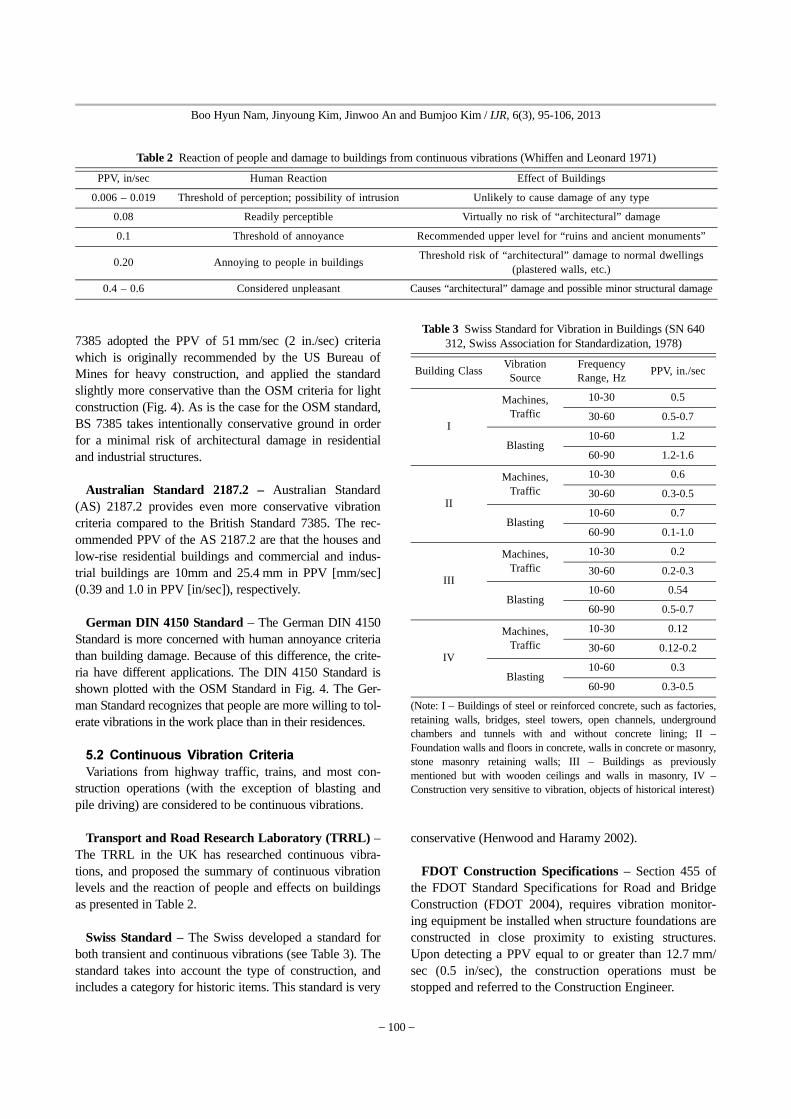
Transport and Road Research Laboratory (TRRL) –The TRRL in the UK has researched continuous vibra-tions, and proposed the summary of continuous vibrationlevels and the reaction of people and effects on buildingsas presented in Table 2.
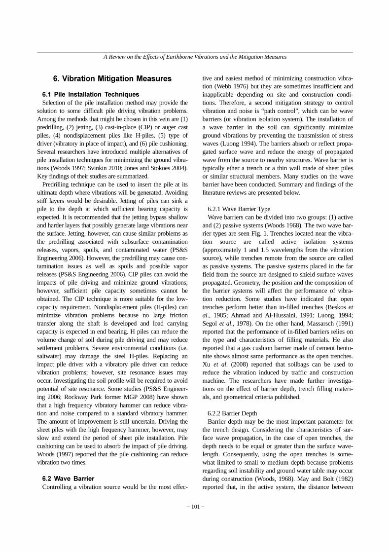
Swiss Standard – The Swiss developed a standard forboth transient and continuous vibrations (see Table 3). Thestandard takes into account the type of construction, andincludes a category for historic items. This standard is very
conservative (Henwood and Haramy 2002).
FDOT Construction Specifications – Section 455 ofthe FDOT Standard Specifications for Road and BridgeConstruction (FDOT 2004), requires vibration monitor-ing equipment be installed when structure foundations areconstructed in close proximity to existing structures.Upon detecting a PPV equal to or greater than 12.7 mm/sec (0.5 in/sec), the construction operations must bestopped and referred to the Construction Engineer.
Table 2 Reaction of people and damage to buildings from continuous vibrations (Whiffen and Leonard 1971)
PPV, in/sec Human Reaction Effect of Buildings
0.006 – 0.019 Threshold of perception; possibility of intrusion Unlikely to cause damage of any type
0.08 Readily perceptible Virtually no risk of “architectural” damage
0.1 Threshold of annoyance Recommended upper level for “ruins and ancient monuments”
0.20 Annoying to people in buildingsThreshold risk of “architectural” damage to normal dwellings
(plastered walls, etc.)
0.4 – 0.6 Considered unpleasant Causes “architectural” damage and possible minor structural damage
Table 3 Swiss Standard for Vibration in Buildings (SN 640 312, Swiss Association for Standardization, 1978)
Building ClassVibration
SourceFrequency Range, Hz
PPV, in./sec
I
Machines,Traffic
10-30 0.5
30-60 0.5-0.7
Blasting10-60 1.2
60-90 1.2-1.6
II
Machines,Traffic
10-30 0.6
30-60 0.3-0.5
Blasting10-60 0.7
60-90 0.1-1.0
III
Machines,Traffic
10-30 0.2
30-60 0.2-0.3
Blasting10-60 0.54
60-90 0.5-0.7
IV
Machines,Traffic
10-30 0.12
30-60 0.12-0.2
Blasting10-60 0.3
60-90 0.3-0.5
(Note: I – Buildings of steel or reinforced concrete, such as factories,retaining walls, bridges, steel towers, open channels, undergroundchambers and tunnels with and without concrete lining; II –Foundation walls and floors in concrete, walls in concrete or masonry,stone masonry retaining walls; III – Buildings as previouslymentioned but with wooden ceilings and walls in masonry, IV –Construction very sensitive to vibration, objects of historical interest)
A Review on the Effects of Earthborne Vibrations and the Mitigation Measures
101
6. Vibration Mitigation Measures
6.1 Pile Installation Techniques
Selection of the pile installation method may provide thesolution to some difficult pile driving vibration problems.Among the methods that might be chosen in this vein are (1)predrilling, (2) jetting, (3) cast-in-place (CIP) or auger castpiles, (4) nondisplacement piles like H-piles, (5) type ofdriver (vibratory in place of impact), and (6) pile cushioning.Several researchers have introduced multiple alternatives ofpile installation techniques for minimizing the ground vibra-tions (Woods 1997; Svinkin 2010; Jones and Stokoes 2004).Key findings of their studies are summarized.
Predrilling technique can be used to insert the pile at itsultimate depth where vibrations will be generated. Avoidingstiff layers would be desirable. Jetting of piles can sink apile to the depth at which sufficient bearing capacity isexpected. It is recommended that the jetting bypass shallowand harder layers that possibly generate large vibrations nearthe surface. Jetting, however, can cause similar problems asthe predrilling associated with subsurface contaminationreleases, vapors, spoils, and contaminated water (PS&SEngineering 2006). However, the predrilling may cause con-tamination issues as well as spoils and possible vaporreleases (PS&S Engineering 2006). CIP piles can avoid theimpacts of pile driving and minimize ground vibrations;however, sufficient pile capacity sometimes cannot beobtained. The CIP technique is more suitable for the low-capacity requirement. Nondisplacement piles (H-piles) canminimize vibration problems because no large frictiontransfer along the shaft is developed and load carryingcapacity is expected in end bearing. H piles can reduce thevolume change of soil during pile driving and may reducesettlement problems. Severe environmental conditions (i.e.saltwater) may damage the steel H-piles. Replacing animpact pile driver with a vibratory pile driver can reducevibration problems; however, site resonance issues mayoccur. Investigating the soil profile will be required to avoidpotential of site resonance. Some studies (PS&S Engineer-ing 2006; Rockway Park former MGP 2008) have shownthat a high frequency vibratory hammer can reduce vibra-tion and noise compared to a standard vibratory hammer.The amount of improvement is still uncertain. Driving thesheet piles with the high frequency hammer, however, mayslow and extend the period of sheet pile installation. Pilecushioning can be used to absorb the impact of pile driving.Woods (1997) reported that the pile cushioning can reducevibration two times.
6.2 Wave Barrier
Controlling a vibration source would be the most effec-
tive and easiest method of minimizing construction vibra-tion (Webb 1976) but they are sometimes insufficient andinapplicable depending on site and construction condi-tions. Therefore, a second mitigation strategy to controlvibration and noise is “path control”, which can be wavebarriers (or vibration isolation system). The installation ofa wave barrier in the soil can significantly minimizeground vibrations by preventing the transmission of stresswaves (Luong 1994). The barriers absorb or reflect propa-gated surface wave and reduce the energy of propagatedwave from the source to nearby structures. Wave barrier istypically ether a trench or a thin wall made of sheet pilesor similar structural members. Many studies on the wavebarrier have been conducted. Summary and findings of theliterature reviews are presented below.
6.2.1 Wave Barrier TypeWave barriers can be divided into two groups: (1) active
and (2) passive systems (Woods 1968). The two wave bar-rier types are seen Fig. 1. Trenches located near the vibra-tion source are called active isolation systems(approximately 1 and 1.5 wavelengths from the vibrationsource), while trenches remote from the source are calledas passive systems. The passive systems placed in the farfield from the source are designed to shield surface wavespropagated. Geometry, the position and the composition ofthe barrier systems will affect the performance of vibra-tion reduction. Some studies have indicated that opentrenches perform better than in-filled trenches (Beskos etal., 1985; Ahmad and Al-Hussaini, 1991; Luong, 1994;Segol et al., 1978). On the other hand, Massarsch (1991)reported that the performance of in-filled barriers relies onthe type and characteristics of filling materials. He alsoreported that a gas cushion barrier made of cement bento-nite shows almost same performance as the open trenches.Xu et al. (2008) reported that soilbags can be used toreduce the vibration induced by traffic and constructionmachine. The researchers have made further investiga-tions on the effect of barrier depth, trench filling materi-als, and geometrical criteria published.
6.2.2 Barrier DepthBarrier depth may be the most important parameter for
the trench design. Considering the characteristics of sur-face wave propagation, in the case of open trenches, thedepth needs to be equal or greater than the surface wave-length. Consequently, using the open trenches is some-what limited to small to medium depth because problemsregarding soil instability and ground water table may occurduring construction (Woods, 1968). May and Bolt (1982)reported that, in the active system, the distance between

102
Boo Hyun Nam, Jinyoung Kim, Jinwoo An and Bumjoo Kim / IJR, 6(3), 95-106, 2013
vibration source and barrier is not significant from a prac-tical viewpoint but the depth has significant influence onthe vibration reduction. Haupt (1995) also indicated thatthe effectiveness of passive systems does not depend onthe distance from the vibrating source but the dimension(depth and width) of the system. There have been studiesshowing the relationship between the trench depth and thewavelength of the relevant Rayleigh wave (Ahmad andAl-Hussaini 1991; Al-Hussaini and Ahmad 1991; Al-Hus-saini and Ahmad 1996). For the influence of trench width,Fuyuki and Matsumoto (1980) reported that the width isimportant affecting factor for the shallow open trencheswhereas Woods (1968) and Segol et al. (1978) concludedthat the width is not a relevant factor.
6.2.3 Trench MaterialMany studies have shown good performance of in-filled
trenches and they addressed the influence of trench fillingmaterials. Beskos et al. (1985), Ahmad and Al-Hussaini(1991), Luong (1994), and Segol et al. (1978) concludedthat open trenches are more effective wave barriers thaninfilled trenches but they also addressed that the opentrench applications are not very practical due to the soil (orwall) stability. Al-Hussaini and Ahmad (1996) indicatedthat concrete, bentonite, soil bentonitemixtures are themost common filling materials. Other materials such asextended polysterene (EPS) and rubber modified asphalthave been used to fill the trench (Zeng et al., 2001; Zhonget al., 2002; Itoh, 2003; Itoh et al., 2005). A gas cushionbarrier made of cement bentonite was introduced by Mas-sarsch (1991) and the study shows the comparable perfor-mance to open trenches. Itoh et al. (2005) investigated theperformance of aluminum and geofoam as trench materi-als and his conclusion was that geofoam works better thanaluminum. Wang et al. (2006) also studied the perfor-mance of geofoam wave barrier and showed the attenua-tion of stress waves in a concrete layer barrier.
6.2.4 Geometrical CriteriaWoods (1968) suggested the amplitude reduction ratio,
ARR, for evaluating the isolation efficiency of wave bar-rier systems. ARR is the ratio of the magnitude of verticaldisplacement with a barrier (A1) to the magnitude of verti-cal displacement without a barrier (A0) (Woods, 1968;May and Bolt, 1982). The equation is presented as below.
ARR = A1 / A0 (6)
Lower ARR provides better the isolation performance ofwave barriers. When ARR equal to 0.25 or lower, the wavebarrier would provide satisfactory performance (Woods,
Fig. 5 Vibration isolation system: (a) active and (b) passive systems (Woods, 1968).
Table 4 Geometrical criteria for the passive system(for ARR=0.25)
PassiveReferences
Open In-filled
D1W0.1
Beskos et al., 1985
D1W0.1
D1.5 concrete barrierW0.2 concrete barrier
Ahmad and Al-Hussaini,
1991
D(1 – 1.5)ARR insensitive for all W
May and Bolt, 1982
Table 5 Geometrical criteria for the active barrier system(for ARR=0.25).
PassiveReferences
Open In-filled
D0.6ARR insensitive for all W
D x W1.5 very strong dependence
of ARR on W when D is weak
Beskos et al., 1985
D0.6 Woods, 1968
D0.6ARR insensitive for all W
May and Bolt, 1982

A Review on the Effects of Earthborne Vibrations and the Mitigation Measures
103
1968; Richart et al., 1970). Several researchers have estab-lished the geometrical criteria for active and passive sys-tems (either open or in-filled trenches). Table 1summarizes the geometrical criteria for ARR equal to 0.25.
7. Current Practices ofGround Vibration Control
A survey of state DOTs was by Minnesota Departmentof Transportation (MnDOT) focusing on the current prac-tices how to mitigate the ground vibration due to urbanconstruction (i.e. road/soil compaction, pile driving, blast-ing or pavement breaking) as well as heavy traffic loading
(Ref). Key findings of the survey are summarized in Table6 and additional information is presented herein.
The states of Louisiana and New Hampshire are recently undertaking the researches on the effects of construction-related ground vibration and their mitigation measures.Florida has their own recommended practice for estimat-ing the effect of vibratory compaction of hot mix asphalt(HMA) for roadway surface. Several states includingGeorgia, Montana, New Hampshire, and New Jersey, havegeneral guidelines or standard specifications to cover con-structions involved with vibration impacts. None of thestate DOTs address on the subject of educating the publicin their policies, standards, or practices.
Table 6 Summary of the survey on state DOT practices (MnDOT TRS 2012).
StateQ1. What does your policy
(standard) address?
Q2. What vibration activities are addressed in your policy
(standard)?
Q3. Preconstruction survey factors
Q4. Vibration monitoring factors
FloridaImpact or damage to property
and human annoyance
Vibratory compaction of hot mix asphalt concrete for
roadway surfaces
Predesign testing is conducted using a Falling Weight
Deflectometer
Predicted vibration levels I. Predicted vibration levels II.
Georgia
Impact or damage to property, educating the public about the
potential for damage and nuisance.
Blasting, pile driving, soil compaction, pavement
breaking, and demolition.
Distance (within approximately 75-100 feet). Predicted
vibration levels I (> 2.0 in/s). Soil conditions. Structures
condition. Complaints received regarding the project.
Distance (within approximately 75-100 ft). Predicted vibration
levels I (> 2.0 in/s). Soil conditions. Structures
condition. Complaints received regarding the project.
Michigan Impact or damage to property. Blasting, pile driving, soil
compaction, pavement breaking, and demolition.
Distance (generally 100ft for residential structures).
Predicted vibration levels I. Number and location of
structures.
Distance, Predicted vibration levels I (AASHTO R-8). Soil
conditions. Number and location of structures.
MontanaImpact or damage to property and visualization techniques.
Blasting, pile driving (sometimes), soil compaction,
pavement breaking, and demolition.
Distance None
New Hampshire
Impact or damage to property
Blasting, pile driving, soil compaction, equipment traffic,
pavement breaking, and demolition.
Distance (500 ft for blasting). Predicted vibration levels I. Predicted vibration levels II. Soil conditions. Number and location of structures. Project
size and duration. Public visibility.
Distance (500 ft for blasting). Predicted vibration levels I. Predicted vibration levels II. Soil conditions. Number and location of structures. Project
size and duration. Public visibility
New JerseyImpact or damage to property,
best practices for public engagement
Blasting, pile driving, and sheeting
Distance. Predicted vibration levels I. Predicted vibration
levels II. Soil conditions. Number and location of
structures.
Distance. Predicted vibration levels I, Predicted vibration
levels II, Soil conditions. Number and location of
structures.
Utah Impact or damage to property
Blasting, pile driving, soil compaction, equipment traffic,
pavement breaking, and demolition.
Distance (about ½ mile). Predicted vibration levels I
(2 in/s).
Distance (about ½ mile). Predicted vibration levels I
(2 in/s).
Note: Arkansas, Louisiana, Oklahoma, and Indiana have no policy

104
Boo Hyun Nam, Jinyoung Kim, Jinwoo An and Bumjoo Kim / IJR, 6(3), 95-106, 2013
8. Summary and Conclusion
Earthborne vibrations are caused by construction activi-ties (i.e. roadbed compaction, pile driving, and blasting)and transit (i.e. train, truck, and bus). The stress wavesinduced by the earthborne vibrations propagate throughthe ground and may or may not damage nearby buildingsand structures. The level of ground and structure vibra-tions depends on the construction source, geotechnicalcondition (soil, ground water, and bedrock depth), dis-tance from the source, wave propagation characteristics ata site, and the sensitivity of buildings and structures. Thecommon practices for the vibration control and mitigationmeasures include: (1) the criteria of vibration limit so thatthe contractors follow the guideline, (2) preconstructionsurvey and vibration monitoring so that the performanceof contractors can be evaluated, (3) the use of alternativeconstruction methods (i.e. predrilling, jetting, cast-in-place,and pile cushioning methods for pile driving), and (4)wave barrier to reduce the vibration energy traveledthrough the ground.
The effects of ground vibration are significantly affectedby local site condition. In particular, the site conditionsuch as ground water table, soil layers and stiffness, andbedrock depth will determine the site resonance, the char-acteristics of wave propagation, and soil interactionbetween the ground and building. These local conditionswill determine the level of structure damage. Thus, therecommendations based on this review study are to con-tinue further study on the subject of: (1) the vibrationeffects and vibration criteria of different structures, (2) themodification of a vibration prediction equation of groundvibration as well as vibration criteria that takes intoaccount of local site conditions, and (3) the developmentof mechanistic model of dynamic settlement due to earth-borne vibration.
Acknowledgement
The authors thank the financial support and assistance ofFlorida Department of Transportation.
References
1. Ahmad, S., Al-Hussaini, T. M., Fishman, K. L. (1996).“Investigation on Active Isolation of Machine Foundationsby Open Trenches,” J. Geotech. Engrg., Vol. 122, No. 6, pp.454-461.
2. Ahmad, S., Al-Hussaini, T. M. (1991). “Simplified Designfor Vibration Screening by Open and In-filled Trenches,”Journal of Geotechnical Engineering, ASCE, Vol. 117, No.
1, pp. 67-88.3. Ahmad, S., Al-Hussaini, T. M. (1991). “Simplified Design
for Vibration Screening by Open and In-filled Trenches,” J.Geotech. Engrg., Vol. 117, No. 1, pp. 67-88.
4. Al-Hussaini, T. M., Ahmad, S. (1996). “Active Isolation ofMachine Foundations by In-filled Trench Barriers,” J. Geo-tech. Engrg., Vol. 122, No. 4, pp. 288-294.
5. Al-Hussaini, T. M., Ahmad, S. (1991). “Design of WaveBarriers for Reduction of Horizontal Ground Vibration,” J.Geotech. Engrg., Vol. 117, No. 4, pp. 616-636.
6. Al-Hussaini, T. M., Ahmad, S. (1996). “Active Isolation ofMachine Foundation by In-filled Trench Barriers,” Journalof Geotechnical Engineering, ASCE, Vol. 122, No. 4, pp.288-294.
7. Amick, H., Gendreau, M. (2000). “Construction Vibrationsand Their Impact on Vibration-sensitive Facilities,” Proceed-ings of the sixth construction congress, American Society ofCivil Engineers, Orlando, Florida, February 2000, pp. 758-767.
8. Balachandran, C. G. (1998). “Assessment of ConstructionVibration Impacts on Historic Structures,” Journal of theAcoustic Society of America, Vol. 103, Issue 5, pp. 3022-3022.
9. Barkan, D. D. (1962). Dynamics of Bases and Foundations,translated from the Russian by L. Drashevska, edited by G. P.Tschebotarioff, McGraw-Hill.
10. Beskos, D. E., Dasgupta, G., Vardoulakis, I. G. (1985). Vibra-tion isolation of machine foundations. ISBN 0872624927.In: Gazetas, G., Selig, E.T. (Eds.), Vibration Problems inGeotechnical Engineering. ASCE, New York, pp. 138-151.
11. Bornitz, G. (1931). Uber die Ausbreitung der von Groszkol-benmnaschinen erzeungten Bodenschwingungen in dieTiefe, J. Springer, Berline.
12. Clough, G. W., Chameau, J. L. (1980). “Measured Effects ofVibratory Sheet Pile Driving,” Journal of Geotechnical Engi-neering Division, ASCE, Vol. 106, No. GT10, pp. 1081-1099.
13. Dalmatov, B. I., Ershov, V. A., Kovalevsky, E. D. (1968).“Some Cases of Foundation Settlement in Driving Sheetingand Piles,” Proceedings International Symposium on WaveProperties of Earth Materials, pp. 607-613.
14. Deutsches Institut fuer Normung (DIN 4150) (1986). Deut-sche Normen: Erschûtterungen im Bauwesen-Einwirkungenauf bauliche Anlegen, Germany.
15. Earthquake Engineering and Soil Dynamics, St. Louis, MO,11–15 March 1991. University of Missouri at Rolla, Rolla,MO, pp. 1461-70.
16. Florida Department of Transportaiton (2004). Standard Spec-ifications for Road and Bridge Contruction, Tallahassee, FL.
17. Fuyuki, M., Matsumoto, Y. (1980). “Finite Difference Anal-ysis of Rayleigh Wave Scattering at a Trench,” Bulletin ofthe Seismological Society of America, Vol. 70, pp. 2051-2069.
18. Hanson, C. E., Towers, D. A., Meister, L. D. (2006). “Tran-sit Noise and Vibration and Impact Assessment”, Report

A Review on the Effects of Earthborne Vibrations and the Mitigation Measures
105
FTA-VA-90-1003-06, Office of Planning and Environment,Federal Transit Administration. http://www.wsdot.wa.gov/projects/viaduct/Media/Default/Documents/Environmental/EAGNoiseVibration.pdf.
19. Heckman, W. S., Hagerty, D. J. (1978). “Vibrations Associ-ated with Pile Driving”, Journal of the Construction Divi-sion, ASCE, Vol. 104, No. CO4, pp. 385-394.
20. Henwood, J. T., Haramy, K. Y. (2002). “Vibrations Inducedby Construction Traffic: A Historic Case Study” Presented atGeophysics 2002, April 15-19, 2002, www.dot.ca. gov/hq/esc/geotech/gg/geophysics2002/043henwood_construction_vibrations.pdf (accessed May 17, 2005).
21. Itoh, K. (2003). “Physical Modelling of Wave Propagationfrom Ground Vibration and Vibration Countermeasure,”PhD Dissertation, Tokyo Institute of Technology.
22. Itoh, K., Zeng, X., Koda, M., Murata, O., Kusakabe, O.(2005). “Centrifuge Simulation of Wave Propagation due toVertical Vibration on Shallow Foundations and VibrationAttenuation Countermeasures,” Journal of Vibration andControl, Vol. 11, pp. 781-800.
23. Jackson, N. M., Hammons, M. I., Walker, R., Von Quintus,H. (2007). “Use of Nondestructive Techniques to Estimatethe Allowable Vibratory Compaction Level During Con-struction”, Research Report FL/DOT/SMO/07-BDB-11,Florida Department of Transportation, March 2007.
24. Luong, M. P. (1994). Efficiency of a stress wave mitigationbarrier. Proceedings of the International Conference on Cen-trifuge Modelling (Centrifuge 94), Balkema, Singapore, pp.283-88.
25. Massarsch, K. R. (1991). Ground vibration isolation usinggas cushions. In: Proceedings of the 2nd International Con-ference on Recent Advances in Geotechnical.
26. May, T. W., Bolt, B. A. (1982). “The Effectiveness ofTrenches in Reducing Seismic Motion,” Earthquake Engi-neering and Structural Dynamics, Vol. 10, No. 2, pp. 195-210.
27. Minnesota Department of Transportation (2012). “Impact ofVibratory Equipment to Surrounding Environments duringConstruction,” Transportation Research Synthesis 1201, July2012.
28. Nichols, H. R., Johnson, C. F., Duvall, W. I. (1971). “Blast-ing Vibrations and their Effects on Structures,” Bulleting656, U.S. Bureau of Mines, Department of the Interior,Washington, D.C.
29. Peng, S. M. (1972). “Propagation and Screening of RayleighWaves in Clay,” Master’s Engineering Thesis no. 386, AsianInstitute of Technology, Bangkok.
30. PS&S Engineering, “Proposed Noise/Vibration MitigationPlan for Pile Driving Related Noise and Vibration”, Reportto the Department of Environmental Conservation, April2006. http://www.dec.ny.gov/docs/remediation_hudson_pdf/noisemitigation.pdf (accessed on March 2012).
31. Rausch, E. (1942). “Maschinenfundamente und AndereDynamische Bauaufgaben,” Vertrieb VDI, Verlag G.M.B.H.,Berlin, Germany.
32. Richart, F., Hall, J., Woods, R. (1970). Vibrations of Soilsand Foundations. Prentice Hall, Englewood Cliffs, NJ.
33. Rockway Park former MGP (2008). “Noise/Vibration Miti-gation Plan for: Noise and Vibration Related to the Installa-tion of Sheet Piles,” http://www.rockawayparkmgpsite.com/pdfs/Appendix_L.pdf (accessed March 20, 2013).
34. Segol, G., Lee, P. C. Y., Abel, J. R. (1978). “AmplitudeReduction of Surface Waves by Trenches,” Journal of theEngineering Mechanics Division, ASCE, Vol. 104, No. 3,pp. 621-641.
35. Siskind, D. E., Stagg, M. S., Kopp, J. W., Dowding, C. H.(1980). “Structure Response and Damage Produced byGround Vibrations from Surface Blasting,” RI 8507, U.S.Bureau of Mines, Department of Interior, Washington, D.C.
36. Sivinkin, M. R. Drawbacks of Blast Vibration Regulations,www.vulcanhammer.net/Svinkin//BLST-CRT.pdf (accessedMay 17, 2013).
37. Standards Australia (1983). Explosives-Storage, Transport,and Use, AS 2187.2, Sydney, Australia.
38. Svinkin, M. R. (2002). “Predicting Soil and Structure Vibra-tions from Impact Machines,” Journal of Geotechnical andGeoenvironmental Engineering, Vol. 128, No. 7, pp. 602-612.
39. Swiss Association of Standarization (1978). Effects of Vibra-tion of Construction, SN 640 312, Zurich, Switzerland.
40. Tao, M., Zhang, M. (2012). “Update LADOTD Policy onPile Driving Vibration Management”, Report FHWA/LA.11/483, Louisiana Department of Transportation, February2012.
41. Wang, Z.-L., Chi, Yong, Wang, J. C. (2006). “NumericalAnalysis of Attenuation Effect of EPS Geofoam on StressWaves in Civil Defense Engineering,” Geotextiles andGeomembranes, Vol. 24, No. 5, pp. 265-273.
42. Washington State Department of Transportation (2008).Noise and Vibration Technical Memorandum, “SR99: Alas-kan Way Viaduct & Seawall Replacement Program,” (accessedin March 21, 2013).
43. Webb, J. F. (1976). Noise control in industry. SoundResearch Laboratories Limited, Holbrook Hall Sudbury, Suf-folk, U.K.
44. Whiffen, A. C., Leonard, D. R. (1971). “A Survey of Traffic-induced Vibrations”, RRL report LR 418, Transportation andRoad Research Laboratory, Crowthorne, UK.
45. Wiss, J. F. (1981). “Construction Vibrations: State-of-the-art,”Journal of the Geotechnical Engineering Division, ASCE,Vol. 107, No. GT2, February 1981, pp. 167-181.
46. Wiss, J. F., Parmelee, R. A. (1974). “Human Perceoption ofTransient Vibrations”, Journal of the Structural Division,ASCE, Vol. 100, No. 74, pp. 773-787.
47. Woods, R. D. (1968). “Screening of Elastic Waves byTrenches,” Journal of Soil Mechanics Division, ASCE, Vol.94, No. SM4, pp. 951-979
48. Woods, R. D., Jedele, L. P. (1985). “Energy-attenuationRelationships from Construction Vibrations,” VibrationProblems in Geotechnical Engineering, Proceedings of a

106
Boo Hyun Nam, Jinyoung Kim, Jinwoo An and Bumjoo Kim / IJR, 6(3), 95-106, 2013
symposium sponsored by the Geotechnical EngineeringDivision, ASCE, Detroit, Michigan, October 1985, pp 229-246.
49. Xu, Y., Huang, J., Du, Y., Sun, D. (2008). “Earth Reinforce-ment using Soilbags,” Geotextiles and Geomembranes, Vol.26, No. 3, pp. 279-289.
50. Zeng, X., Rose, J., Rice, J. (2001). “Stiffness and Damping
Ratio of Rubber Modified Asphalt Mixes: Potential Vibra-tion Attenuation for High Speed Railway Trackbeds,” Jour-nal of Vibration and Control, Vol. 7, No. 4, pp. 527-538.
51. Zhong, X., Zeng, X., Rose, J. (2002). “Shear Modulus andDamping Ration of Rubber Modified Asphalt Mixes andUnsaturated Subgrades Soils,” ASCE Journal of Materials inCivil Engineering, Vol. 14, No. 6, pp. 496-502.