a review of the analytical and numerical modeling of
TRANSCRIPT

Reports of the Department of Mathematical Information TechnologySeries B. Scientific ComputingNo. B 1/2016
A Review of the Analytical and NumericalModeling of Composites
Anna-Leena Erkkilä Tero Tuovinen
Matti Kurki
University of JyväskyläDepartment of Mathematical Information Technology
P.O. Box 35 (Agora)FI–40014 University of Jyväskylä
FINLANDfax +358 14 260 2209
http://www.mit.jyu.fi/

Copyright © 2016Anna-Leena Erkkilä and Tero Tuovinen and Matti Kurki
and University of Jyväskylä
ISBN 978-951-39-6528-0 (nid.)ISBN 978-951-39-6935-6 (PDF)
ISSN 1456-436X

A Review of the Analytical and NumericalModeling of Composites ∗
Anna-Leena Erkkilä† Tero Tuovinen‡ Matti Kurki§
Abstract
This review article is dedicated to the materials that are made from two ormore constituent materials with different physical and/or chemical properties.The focus is on the materials, where the individual components remain sepa-rate and distinct within the final structure. The new combined material usuallyhave some additional characteristic properties compared to the individual com-ponents, or, in other case, some critical properties of combined material mayfollow almost equally one of the components. Typically, preferred propertiesof the new material can be such as strength, porosity, conductivity or cheap-ness. The ultimate goal of this study is to find methods and tools for achieveadequate strength even when the low quality component is added to primarymaterial or when two or more ’waste’ matters are combined with each other innovel industrial processes. Contribution of this article is to review modelingpossibilities of different composite materials and bring out new ideas to modelcomposites including low quality or waste materials.
1 Introduction
The science and technology of composite materials receives much attention aris-ing from composite’s ability to provide novel and specific properties that exactlymeets the requirements of various industrial applications ranging from aerospaceto bio-medical areas. Nature is full of examples of composite materials and theidea of man-made composite materials is not a novel. Typical engineered compos-ite materials can include cements, concrete, asphalt concrete, fiber-reinforced poly-mers, fiber-reinforced thermoplastics, metal composites, ceramic-metal composites,glass-reinforced plastic, carbon-fiber-reinforced polymer, hemicellulose based com-posites, etc. In this review we restrict our study to manufactured composites, whichare formed by combining two or more physically and/or chemically distinct, suit-ably distributed and arranged phases with an interface separating them. There is∗Report for the project Recycling and Utilization of Waste Matter and Sludge Components†Department of Mathematical Information Technology, University of Jyväskylä, Finland‡Department of Mathematical Information Technology, University of Jyväskylä, Finland§JAMK University of Applied Sciences, Jyväskylä, Finland
1

large variety of subjects, such as macro, micro and nano structure of composite; themechanics – interface, fatigue, environmental interactions – and process modeling,which are under discussion in scientific and engineering community. In this articlewe are looking the field from mathematical modeling point of view, and thereforewe have divided the composites into five categories based on their structural be-havior or production technology. The categorization is not meant to constrict thegeneration of ideas, but to provide fluent basis for different point of views on thetopic. The categories and products belonging to them are overlapping and somematerials may have properties of two or even more groups.
The materials have been categorized as follows:
1. Reinforced materials.
2. Matrix with weakening components or pores.
3. Two material matrices combined together.
4. Heterogeneous materials.
5. Laminates and sandwich-structured composites.
Detailed description with examples of each category is defined in Table 1. Mostcomposites are usually considered to belong to categories 1 or 5. In categories 1 and2, the matrix is considered the primary phase, and discontinuous dispersed phasesecondary. The primary phase (matrix) is generally responsible for providing thebulk form of the material as a whole.
There are several aspects when considering the mathematical modeling of com-posite materials. The behavior of composite materials is determined by the relevantmaterial properties of the constituents and by their geometrical arrangement. Theconstituents may also have different shrinkage and thermal expansions or the mois-ture and humidity may affect them differently. This may cause internal stresses andtheir energy may dissipate during the failure process through micro-cracks. The pri-mary and secondary material are usually bonded together through interface, whichbehavior can be crucial for understanding and for fully determining the mechanicalbehavior of composite.
An usual aim of mechanical studies of heterogeneous materials attends to esti-mate their overall, effective or apparent, behavior (e.g., stiffness, fracture or strengthproperties). The homogenization techniques are commonly used in continuum micro-mechanics of the materials. The Representative Volume Element (RVE) with effec-tive parameters (e.g., effective moduli, effective stress or effective strain) and asymp-totic methods are typical concepts. In these models, the effective properties of a unitcell of the material at the lower scales are determined and used in the higher scales(see, e.g., Zaoui (2002)). The other commonly used method family is called MicroFinite Element Analysis techniques (μFEA). In these methods the number of ele-ments is increased and the size of elements is decreased. The drawback is that thesemodels require substantial computational resources and time. Recently, the multi-scale element models have been in the focus of the latest achievements. They may
2

Table 1: Five categories of different kind of composites based on mathematical mod-eling point of view.
Category Description
Cat
egor
y1
Composites having a primary material forming a basicmatrix, where some other material(s) is (are) used toreinforcement or otherwise to improve the properties. Theprimary phase encloses or surrounds the secondary phase,and shares or transfers imposed mechanical load to andfrom the reinforcing phase. The reinforcing phase materialmay be in the form of discontinuous flakes, particles, fibers,whiskers, or nanoparticles. Common matrices include mud(wattle-and-daub), cement (concrete), polymers (fiberreinforced plastics), metals, ceramics, bitumen (asphaltconcrete) and even some unusual matrices, such as ice(pykrete).
Cat
egor
y2
The materials in category 2 are very much alike as incategory 1, but the material matrix includes dispersedsecondary particles (fillers), which instead of working asreinforcement decrease the mechanical properties ofprimary material. Usually these filler materials are added,because they are cheaper than the main material, or they areimpurities that can not be extracted from raw material. Thetypical printing paper is an example of a composite of thiscategory having cellulose fiber matrix and filler particles,such as CaCO3. The filler decreases price, improve opacityand control gloss, but when used at high amounts, itdecrease the tensile and thickness directional strength ofpaper. Broadly speaking, the porosity of matrix can be seenas one of the examples of this category.
Cat
egor
y3
Materials in category 3 are again very much alike as incategory 1, but there is two matrix combined and mixedtogether, i.e. the reinforcing or secondary phase materialhas a continuous nature. For example, there might be woodfiber network containing long fibers or woven mats of fiberand then some other material, such as ceramic matrix. Wiremesh glass is a representative example.Continued on next page
3

Table 1: (continued)Category Description
Cat
egor
y4
Composite as a heterogeneous structure, where differentmaterials are chemically bonded with each other. Thesestructures may be processed by adhesive pressing andparticle bonding. Particles may be self-binding, or heat(hot-pressing), binding adjacent, adhesives or additivesmay be used. Examples: particleboard and some woodplastic composites formed by extruding.
Cat
egor
y5
Laminates consist of multiple layers. Composite laminatesconsist of fibers in a polymeric metallic or ceramic matrixmaterial. Layers of different materials may be used,resulting in a hybrid laminate. The individual layersgenerally are orthotropic or transversely isotropic.Sandwich-structured composites are composite materialthat is fabricated by attaching two thin surface layers to alightweight thick core. They are widely used in aerospacestructure, infrastructure, etc. The light-weight corematerials are, for example, foam, truss and honeycombcore. The corrugated fiberboard boxes are examples oflaminated structures and sandwich structured composites.Many paper grades are coated and can also be consideredas laminates.
4

include ability to select adaptively the intermediate level that is most suitable fora given problem (see, e.g., Liu et al. (2006)). Analytical approaches and regressionmodels based on empirical data are also common. Some special treatments for crackpropagation and interface region are also introduced.
2 State of art of the categories
In this section, description of common composite modeling schemes and several ex-amples of modeling of the categorized composite structures are presented. Empir-ical, semi-empirical, analytical and numerical models are all considered. Reviewedapplications include industrial products such as rubber-carbon black, concrete, steeland steel fiber reinforced concrete and polymer matrix and different flake boards.Also analytical micromechanial models for fiber composite and porous structures,and laminate models are briefly reviewed.
2.1 Category 1: Reinforced materials
The materials in category 1 contain the primary material forming a basic matrixwhile some secondary material(s) is(are) used to reinforcement or otherwise to im-prove properties of composite. Firstly, a theory of filler reinforcement for the stiff-ening of elastomers is presented, and secondly, analytical micromechanical modelsfor fiber composites are briefly reviewed in this section. Softening modeling of con-crete have been under extensive development for decades and was chosen as anapplication to represent a quasi-brittle material. Brief glance on few examples offiber reinforced concretes and fiber reinforced polymer matrix as a high ductilityand stiffness materials are also provided in this section.
2.1.1 Theory of filler reinforcement
Rigid fillers can usually be used to increase the stiffness of an elastomeric material.Guth (1939) modified the Einstein’s viscosity law (Einstein (1906, 1911)) to predictthe small strain modulus of rubber-carbon black system considering carbon blackspheres as suspended in a continuous rubber matrix. In the model an additionalterm to account for the interaction of fillers at larger filler volume fractions wasincluded. In the article Guth (1945), the model was generalized for ellipsoidal fillerparticles and was extended to the various properties of the matrix and the fillers.Young’s modulus and stress-strain curve were derived as a functions of the volumeconcentration c and compared to experimental studies.
2.1.2 Stiffness predictions for fiber composites, analytical micromechanical mod-els
The simplest treatment of the elastic behavior of aligned long-fiber composites issimply based on a weighted mean between the moduli of the two components,
5

depending only on the volume fraction of fibers. This Rule of Mixtures (ROM)provides two theoretical models: Voigt model (Voigt (1889)) for upper-bound axialloading and Reuss model (Reuss (1929)) for lower-bound transverse loading. AlsoPoisson’s ratio and shear modulus can be derived by following the rules of mixture,and Kim et al. (2001) used the ROM to predict the plastic flow curves for variousvolume fractions of the soft and hard particles. Accurate experimental validationof the longitudinal model has been demonstrate for a number of composites withcontinuous fibers, while the transverse model is generally known as being inade-quate for predicting the transverse modulus. Hashin & Shtrikman (1963) constructthe tighter bounds, in which single variational principle gives both the upper andlower bounds by making appropriate choices of the reference material. Widely usedsemi-empirical Halpin-Tsai equations (Halpin & Kardos (1976)) were developed tocorrect the transverse Young’s modulus and shear modulus, and also to obtain gen-eralized model for predicting properties of short-fiber composites. Halpin’s andTsai’s derivation for the analytical form of equations was based on Hermans solu-tion (Hermans (1967)) of the self consistent micromechanical model developed byHill (1964), while fiber geometry have accounted through the use of empirical fac-tors.
For short-fiber composites, the fundamental result used in several different mod-els is Eshelby’s solution for ellipsoidal fibers in dilute concentrations fractions (Es-helby (1957)). The key result was to show that within an ellipsoidal inclusion thestrain is uniform, and is related to transformation strain by so called Eshelby’s ten-sion, which depends only the inclusion aspect ratio and the matrix elastic constants.A detailed derivation and applications are presented in Murakami (1988).
For non-dilute concentrations, for example, Mori-Tanaka (Mori & Tanaka (1973),Benveniste (1987)) and self-consistent methods (Hill (1965), Budiansky (1965)) arepresented. In the Mori-Tanaka method the Eshelby approach was combined withthe effective field concept by defining strain concentration tensor, which relates thestrain in inclusion to a far-field strain equal to the appropriate average strain in thematrix. Tandon & Weng (1984) developed equations for the complete set of elasticconstants of the a short-fiber composite based on Mori-Tanaka approach. For thecomputation of the transformation strain in the self-consistent methods the singleparticle is embedded in the effective medium of composite, which properties arenot known a priori. The original work focused on spherical particles and continuousaligned fibers, but approaches for short fiber composite is developed, see, e.g., Chouet al. (1980).
Shear lag model developed for paper and fibrous materials (Cox (1952)) analyzesthe transfer of tensile stress between the fiber and the matrix by means of interfacialshear stress. In shear lag models the mechanical properties of composite can beexpressed as a function of the volume fraction and aspect ratio of fibers (Fukuda &Chou (1982)).
6

2.1.3 Numerical models for crack propagation in concrete
As an application in this category the vastly used, studied and modeled concreteis presented. The concrete is a quasi-brittle composite material made of aggregates(coarse gravel, crushed rocks and sand) and cement paste. The mechanical behaviorof concrete is complex and nonlinear in both tension and compression. The domi-nant mechanism of concrete material response to loading is the initiation and prop-agation of cracks. The stiffness degradation is mainly due the material damage:initially invisible micro-cracks caused by shrinkage, thermal expansion and otherphenomena will progress to visible cracks under external loads. Failure accumu-lates through micro-cracks, which are formed due to the cohesion loss between themortar and the aggregate, at interface between the aggregate and the mortar duethe frictional slip, or crushing of the mortar (Nguyen (2005)).
In uniaxial loading, the experimentally observed deformation process is differ-ent in tension and compression. In a compressive test the cracks are parallel to thedirection of the compressive stress, while in a tensile test the direction of crack prop-agation is transverse to the stress direction. Under severe loading (beyond the peakstress), concrete exhibits a strain-softening response, in both tension and compres-sion (see Figures 1 and 2) (Gopalaratnam & Shah (1985)). The experimental obser-vations obtained from the uniaxial tensile and compressive behavior of the concretecan also be applied to multi-axial stress states (Chen & Han (2007)). Two separatekinds of envelopes are used to characterize the concrete behavior in stress stages:the elastic region is defined by the elastic-limit surface, and the maximum-strengthenvelope of the concrete is characterized by the failure surface, see Figure 3. Thesoftening is a combined material/structural property and the stiffness degradationin concrete is mainly caused by the material damage especially in the post-peaksituation (Chen & Han (2007)).
The structure and properties of concrete such as the shape, size and surface struc-ture of aggregates, the water-cement ratio, the used type of cement, and other factorshave influence on behavior of the product. Nevertheless, a concrete is often simu-lated using macroscopic models, where a concrete is treated as a continuum, and be-havior caused by the heterogeneous material structure are included in the constitu-tive law (see, e.g., Nguyen (2005), Lemaitre (1992)). As the behavior of quasi-brittlematerial is considered, the major focus has been on the fracture studies i.e. situa-tions where material is subjected to moderate to severe loading and crack developsand propagates. Main approaches of the continuum modeling for crack propaga-tion can be categorized as the discrete crack approach, the smeared crack approach,non-local fracturing theory, damage mechanics and lattice models.
In the discrete crack approach the aim is in simulation the initiation and propaga-tion of dominant cracks and thus is preferred approach when the structure containsone or a finite number of cracks (Ngo & Scordelis (1967)). It was recognized in earlystudies that the stress and strain fields that are developed at the tip of the crack aresingular and stress criteria were not reliable. The cohesive crack model, developedby Hillerborg et al. (1976) for crack propagation of concrete introduces fracture pro-cess zone (FPZ) locating ahead of the macro-cracks. Significant amount of energy is
7

0
0.2
0.4
0.6
0.8
1.0
1.2
0.5 1.0 1.5 2.5 3.02.0
STRESS RATIO
STRAIN RATIO
Figure 1: Stress-strain behavior of concrete subjected to monotonic and cyclic com-pression. (Schematic figure after Bahn & Hsu (1998))
20 40 60 80 100 120 140
1
2
3
0
Axial Deformation
Axial Stress (MPA)
Figure 2: Stress-deformation curve of concrete under uniaxial cyclic tensile loading.(Schematic figure after Reinhardt et al. (1986))
8

−σ1
−σ2
−σ3σ 1=σ 2=σ 3
Hydrostatic
Elasticlimit
surface
Failuresurface
Figure 3: Failure and elastic limit surfaces in principal stress space. (Schematic fig-ure after Chen & Han (2007))
9

stored in that large FPZ region, containing micro-cracks in which case a crack canhave stable growth before peak load. Cohesive stress as a function of crack open-ing reaches tensile strength at the tip of the crack and reduces to zero when thereis the critical opening of the crack. The area under the softening stress-separationcurve is equal to the energy release rate of the structure. The propagation of discretecracks through elements requires the refinement and re-meshing of the finite ele-ment mesh. Meshless methods, such as element-free Galerkin methods, have alsobeen applied to avoid difficulties for constant redefinition of the mesh topology (see,e.g., Belytschko et al. (1994), Dong et al. (2010)). Recently, so-called extended finiteelement method (X-FEM) (Sukumar et al. (2000)) and strong discontinuity approach(Oliver & Huespe (2004)) have been introduced to overcome disadvantages of thediscrete crack approach and avoiding need of remeshing. One of the challenges as-sociated with discrete crack models are that they require material properties that aredifficult to measure.
In the smeared crack approach the cracked material is assumed to remain a con-tinuum as an infinite number of cracks are theoretically distributed (smeared) overthe element (Rashid (1968)). The propagation of cracks is modeled as the reductionof the strength and stiffness. The result is non-linear constitutive models with elas-tic degradation and/or softening plasticity (see, e.g., Bažant & Planas (1998), Carol& Bažant (1997), Weihe et al. (1998), Ohmenhauser et al. (1999), de Borst (2002)).The smeared crack approach was first introduced by Rashid (1968). Bažant & Oh(1983a) proposed crack band model based on work of Hillerborg et al. (1976) tosolve unphysical mesh size sensitivity which is consequence when the strain soft-ening is considered as a characteristic of the material. In the crack band model thedissipated energy in strain softening is related to the fracture energy of the material.
The non-local models are based on the continuum mechanics, where the evolu-tion of stress and changes at the micro-structural level due the loading are basedon such a theories as plasticity and damage mechanics. Dougill introduced the pro-gressive fracturing theory which involved the stiffness lose of the material due toprogressive fracturing during the deformation process (Dougill (1976)). In this ap-proach the material return to a state of zero strain at zero stress by linear elasticunloading. This is based on theoretical assumption that the microcracks are in prin-ciple able to close and no residual strain will remain in the material after unloadingto zero stress. However, in real material some residual strains after unloading areprevailing, since during crack formation some particles loosen from the crack edgeprevent the complete closure of the microcracks. Based on the work of Dougill theelasto-plastic-fracturing theory for concrete was carried out by Bažant & Kim (1979).
Continuum damage mechanics (CDM) was first proposed for creep rupture ofmetals by Kachanov (1958, 1999) and it have become one of the classical tools of thestructural mechanics and concrete modeling, see, e.g., Lemaitre & Chaboche (1990),Faria et al. (1998), Peerlings (1999), Jirásek & Patzák (2001), Jirásek et al. (2004), Luc-cioni et al. (1996), Comi & Perego (2001), Comi (2001), Salari et al. (2004), Nguyen(2005), Genet et al. (2014). Damage theories provide an effective way to charac-terize the microscopic deterioration of material by the macroscopic level variables.
10

The coupling between damage evolution and strain is usually formulated to obeythe irreversible thermodynamic laws, though in principle damage theory can be de-veloped by setting a stress-strain law related to damage and a yield/damage limitfunction (see, e.g., Lee & Fenves (1998), Addessi et al. (2002)). From the thermo-mechanical point of view, the input energy is dissipated during the failure evolu-tion through micro-cracks (Nguyen (2005)). In CDM the definition of damage indi-cator, such as presented by Lemaitre (1992), are used to characterize the form of thestiffness reduction covering the thermodynamic, micro-mechanical and geometricalaspects of the macroscopic representation of the material deterioration. The simplescalar damage variable is obtained by measuring the area of the intersection of alldefects in selected plane and by dividing that area SD with total area of that plane S,i.e. damage variableDn = SD/S, see, e.g., Lemaitre (1984). A scalar damage variablewas first used to describe isotropic damaging, but because the damage of concretecaused by microcracks is usually oriented leading to anisotropic damage, the dam-age tensors of higher order are introduced, see, e.g., Kachanov (1980), Krajcinovic(1985), Murakami (1988), Simo & Ju (1987). The internal state variables can be devel-oped within two alternative frameworks: strain-based or stress-based formulation(Simo & Ju (1987)). In Nguyen (2005), the author presented a formulation of elasto-plastic damage constitutive model based on the use of thermodynamic potentialsproposed by Houlsby & Puzrin (2000). The strain softening and stiffness degrada-tion was modeled by damage mechanics, while the residual strains and some othermacroscopic features are related to and captured by plasticity theory.
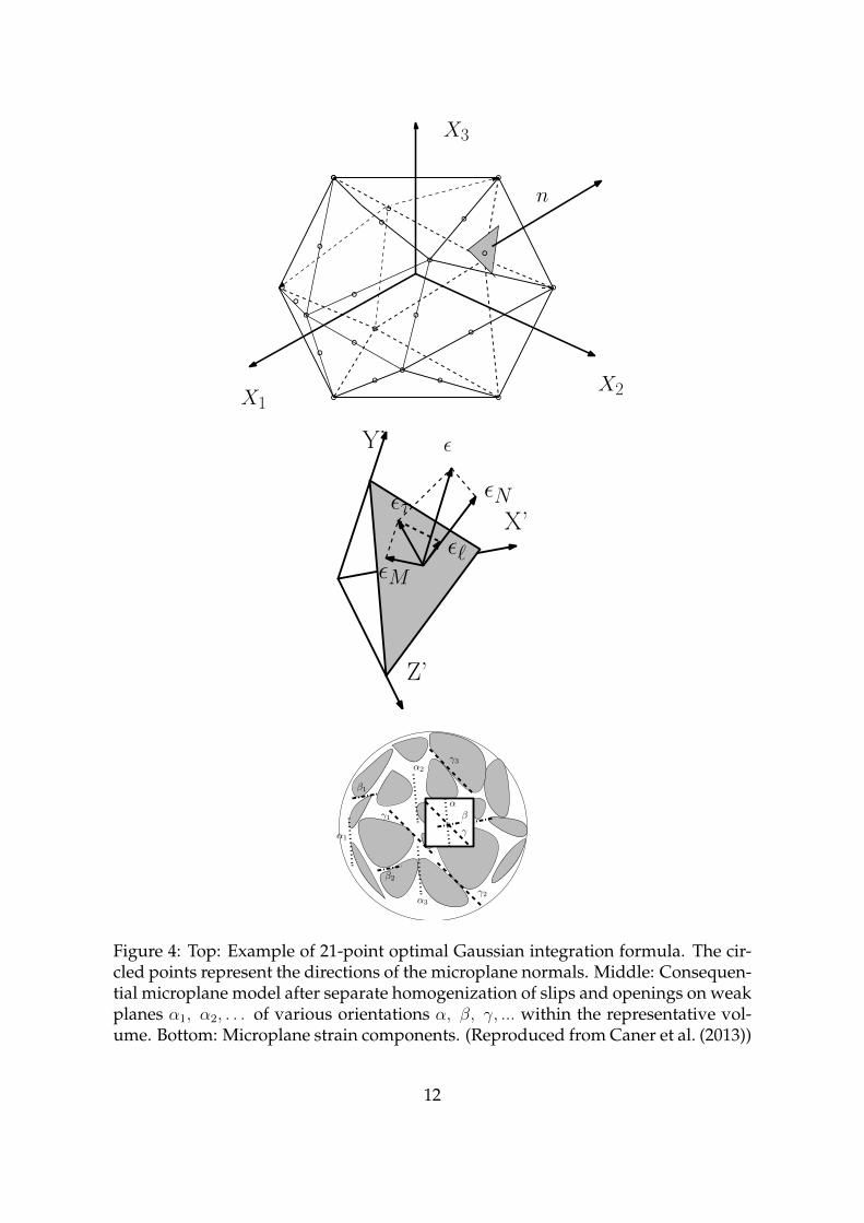
The components of the damage tensors of second, fourth or even eight order(see, e.g., Lemaitre & Chaboche (1990)) are very difficult to identify. The alterna-tive approach to the tensorial damage formulation, the so-called microplane modelhave been proposed by Bazant and Oh (Bažant & Oh (1983b), Bažant & Gambarova(1984)) based on work of Taylor (1938) on plasticity of crystalline metals. In a mi-croplane model the material behavior is modeled in planes of all possible orienta-tion through uniaxial stress-strain laws and in terms of stress and strain vectors (seeFigure 4). The microplane strain and stress vectors are related to the continuum ten-sors by a kinematic constraint and variational principle. The microplane model forconcrete has passed many stages of developments labeled M0,M1,...,M7, see, e.g.,Bažant & Prat (1988), Bažant et al. (2000), Bažant & Caner (2005), Caner & Bažant(2012). The improvement between stages have been concentrated in tensile crackingand postpeak tensile softening, simultaneous modeling of tensile and compressivefailures, formulation of boundary surfaces and frictional yield limits, creep and ar-bitrary large finite strain. In model M2 a volumetric-deviatoric split of the normalstrains and stresses on the microplanes was introduced to help to control triaxialphenomenon of compression failure. In stage M7 the volumetric-deviatoric split forthe elastic part and for the tensile boundary were abandoned while it was retainedfor the deviatoric stress-strain and compressive normal boundaries, which sum isthen compared with the total normal stress.
In lattice models, the continuum is discretized as a lattices or mesh of truss orbeam elements that transfer forces and which may have different properties, de-
11
X3
X1X2
n
Z’
X’
Y’ ε
ετ
εMε`
εN
β1
β
β2
α1
α
α3
α2
γ1
γ2
γ
γ3
Figure 4: Top: Example of 21-point optimal Gaussian integration formula. The cir-cled points represent the directions of the microplane normals. Middle: Consequen-tial microplane model after separate homogenization of slips and openings on weakplanes α1, α2, . . . of various orientations α, β, γ, ... within the representative vol-ume. Bottom: Microplane strain components. (Reproduced from Caner et al. (2013))
12

pending on weather the element represents a cement paste matrix, aggregate or in-terfacial zone (Schlangen & Van Mier (1992b), Lilliu & van Mier (2003)). Fracture issimulated by a linear elastic analysis of the lattice under loading and eliminating (orpartially eliminating) an element that exceeds a criteria threshold of quantities suchas strength or energy from the mesh. The weak interface found between the aggre-gates and the cement paste matrix can be treated in simulation by adjusting the ten-sile strength and the modulus of beams or truss that located in this region, as well aspermitting for differences between aggregates and cement paste matrix (Schlangen& Van Mier (1992a), Cusatis et al. (2003)). The softening can be introduced at ele-ment level or based on elastic purely brittle fracture criterion. The results obtainedcan depend strongly on the chosen element or mesh type and the fracture criterionused. The randomness of lattice is also important to avoid bias in crack propagationdirection. Lattice models assume usually a linear-elastic material constitutive rela-tion and are two-dimensional although some three-dimensional versions have beenintroduced for concrete modeling (Lilliu & van Mier (2003)). Cusatis et al. (2011) in-troduced lattice discrete particle model (LDPM), which is synthesis of confinementshear lattice model and discrete particle models presented in Cusatis et al. (2003)and Pelessone (2005), respectively. LDPM simulates concrete by system of inter-acting aggregate particles connected by a lattice system that is obtained through athree dimensional Delaunay tetrahedralization of the aggregate centers. The consti-tutive behavior is softening for tension and shear-tension and plastic hardening forcompression and shear-compression.
2.1.4 Steel fiber reinforced concrete
The fibers can be used to strengthen the cementitious matrix of concrete, since theyrestrict and delay the progression of microcracks into wide continuous cracks. Es-pecially, steel fibers enhances ductility and energy absorption capability. In the steelfiber reinforced cementitious composite, the mechanical behavior depends on theinterfacial bonding, fiber pull-out, fiber and matrix properties, the fiber orientationand their dispersion in the matrix, flaw size and distribution, etc. (Pereira (2006)).
Ramadoss & Nagamani (2012) present the empirical linear regression models toevaluate the strength and toughness of High Performance Steel Fiber ReinforcedConcrete (HPSFRC). The estimated parameters were compressive strength, modu-lus of rupture, splitting tensile strength and toughness ratio. The eight variablesdefining the mixture proportions of 144 composite specimens (water–cementitiousmaterials ratio, steel fiber volume fraction, superplasticizer dosage, and weight ofcement, fine aggregate, coarse aggregate, water and silica fume) were used in re-gression analysis.
Leite et al. (2004, 2007) applied a mesoscale lattice model for fracture processstudies of concrete and fiber reinforced concrete. The effort was made to create astructural distribution of aggregates and cement paste matrix in a realistic way. Thestochastic-heuristic algorithm was introduced for this purpose. The generated three-dimensional structure specimens were discretized into lattices of linear elements for
13

P
α
S
P
S
σf
σf,1
σf,2
σf,3
εf,1 εf,2 εf,3
εf = s/`b
`b
Figure 5: Procedure to obtain pullout parameters from the experimental force-sliprelationship in Cunha et al. (2011). (Reproduced from Cunha et al. (2011))
both two-dimensional and three-dimensional analysis. After the aggregate-matrixstructure were generated, the fibers were allocated directly into the mesh for fiberreinforcement modeling. Additional elements connecting distant mesh nodes in thecement matrix was introduced. The different softening laws in tension and com-pression was implemented into the constitutive laws of the elements correspondingeither aggregate, matrix or interface. The softening of elements representing fiberswas described by the bond-slip relation.
In model presented in the article Cunha et al. (2011) for Steel Fibre ReinforcedSelf-Compacting Concrete (SFRSCC), a two phase material is assumed. Heteroge-neous concrete medium is treated as one homogeneous phase and another phase iscomposed of steel fibers. The fracture process of the concrete phase is modeled bya three-dimensional smeared crack model and discretized by solid finite elements.The random distribution of short cables imitating steel fibers is simulated usingMonte Carlo method and the geometry, position and orientation of the fibers aresubsequently inserted in a finite element mesh. The fibers are embedded in theconcrete matrix as a three-dimensional truss elements to model the stress transferbetween crack planes due to the fibers bridging a progressive crack. The bond–slipbehavior of the steel fibers was derived from the experimental pullout stress–sliprelationship (Figure 5).
The microplane models M5 and M7 for concrete, presented in previous chap-ter, have been generalized for simulation of fiber reinforced concrete in referencesBeghini et al. (2007) and Caner et al. (2013). For fiber reinforced concrete model M5fthe softening law of stress–strain boundaries of concrete model M5 is modified toenhance ductility. The coupling of kinematically and constrained microplane sys-tems allows simulating the evolution of microcracks of many orientations into widecracks of one distinct orientation. More realistic determination of the fiber pulloutand breakage was brought to microplane model M7f to model fiber reinforced con-crete including gradual activation of fibers bridging an opened crack as is presentedin Figure 6 (Caner et al. (2013)).
14

Crack0
0.20 0.4 0.6 0.8 1
5
10
15
25
σfN (MPa)
Idealised fiber law
CMOD
Figure 6: The fiber law used in the modeling of fiber behavior obtained by gradualactivation of fibers bridging an opened crack. Stages: Hardening, crack openingsand softening. (Reproduced after Caner et al. (2013))
15

2.1.5 Polymer matrix and steel fibers
In the article Sabuncuoglu et al. (2015) the micro-scale finite element modeling isused to estimate the stress concentration under transverse loading in a compositecomposed from polymer matrix and steel fibers. Three different packing types offibers were considered: single fiber in a matrix, hexagonally packed and randomlypacked fibers. The fibers had either circular or hexagonal cross-sectional shape. Forthe model of a single fiber, the dimensions of the model were 15 times the diame-ter of the fiber in the transverse directions to prevent the edge effect on the stressdistribution, while the hexagonal and random fiber packing types includes 30–35fibers per representative volume to adequately represent the behavior of the ran-dom composite. There were large contrast between fiber and matrix stiffness: thematrix material, epoxy, had Young’s modulus of 3 GPa, while it is for steel fibers193 GPa. In the finite element meshing two layers of fiber–matrix interface regionswere generated and dense mesh with equally sized elements was constructed inthese regions since some of the fibers could locate close to each other. The widthof these elements was 0.005 times the fiber diameter and matrix material propertieswere assigned to these elements. They were assumed to be perfectly bonded to thefibers and the rest of the matrix.
2.2 Category 2
The materials in category 2 contain the matrix of primary material and dispersedsecondary particles (fillers) that decrease the mechanical properties of primary ma-terial. Secondary material may be containing added fillers or impurities that are notextracted from raw material. The porosity and flaws in the matrix is also consideredas an example of this category. Printing paper containing clay filler and porous bonestructure are examples presented in this section.
2.2.1 Paper and fillers
The filler pigments are incorporated into paper to reduce the raw material cost andimprove the paper’s optical properties. However, addition of the high filler amountin the paper causes loss of strength, bulk and stiffness. For unfilled paper, the semi-empirical Page equation (Page (1969)) for tensile strength of paper is widely andsuccessfully used. Page derived his model starting from the experimental observa-tion that tensile strength is proportional to the fraction of broken fibers across therupture zone depending on both the strength of individual fibers and the strength ofthe bonds between them. The equation is function of zero-span tensile strength, areaof average fiber cross section, relative bonded area, density of fibers, fiber width,perimeter of the fiber cross section and shear bond strength per unit bonded area(breaking stress of bonds). In principally, the fiber-fiber bonding is responsible forthe internal cohesion of a paper sheet and technologically the inter-fiber bondingis easier alter than fiber properties (see, e.g., Retulainen & Ebeling (1993); Alava &Niskanen (2006)). The effects of filler on tensile strength were considered through a
16

modified Page Equation by Beazley et al. (1975) and Li et al. (2002). The inter-fiberbonding strength is traditionally assumed to depend on two independent factors:bonded area and specific bond strength (see Nordman (1958)). In derivation of themodified equation for filler addition, it was assumed that reduction on strength isproportional to the total surface area of filler in the sheets. The sum of specificbond strength between available surface areas of filler and fibers and between avail-able surface areas of free fibers and fibers are combined to replace the shear bondstrength per unit bonded area. In the model, it was assumed that the filler/fiberspecific shear bond is zero for inorganic fillers. Thus in the modified equation, theeffect of filler on the paper tensile strength depends solely on the filler particle sizeand the amount of fillers in a paper sheet. In the study of Yoon (2007) the modifiedPage theory was found suitable to model tensile strength improvement of paperfilled with clay-starch composite filler, see Figure 7.
Attempts to simulate paper properties by 3D structural model including treat-ments for fibers, fines and fillers have been presented by Nilsen et al. (1998), Niska-nen et al. (1997), and Lavrykov et al. (2012). In KCL-PAKKA model the three-dimensional paper sheet structure is formed by deposing single fibers of rectan-gular cross-section randomly on a flat surface. Each fiber with defined bendingstiffness is let to settle freely as low as possible without deforming the underlyingsheet. The modeled artificial 3D sheet has been used for simulations of porosity andgas diffusion through sheet (Hellen et al. (2002)) and light scattering (Nilsen et al.(1998)). Hjelt et al. (2008) utilized KCL-PAKKA simulation to estimate the effect offiller clusters on bulk of a sheet. Lavrykov et al. (2012) unified several models togenerate 3D fiber networks for simulations of mechanical properties. Separate ap-proaches for formation of representative structure of hand sheet and machine sheetwere presented. A set of objects was defined for the hand sheet simulations: fibershaving non-collapsed or collapsed structure and fines and fillers having only onefinite element in thickness direction. In machine sheet formation simulations thethree-dimensional Navier-Stokes equations were used to describe the fluid motionof fiber suspension. Different boundary conditions were applied to simulate differ-ent processes in paper machine forming section. The final low consistency pulp mapwas used as initial input data for the network compression model implemented byLS-DYNA program (Hallquist (2006)). The elastic modulus was determined fromfiber network by simulating the physical tensile test (Lavrykov et al. (2012)).
2.2.2 Porosity and multi-scale modeling
Podshivalov et al. (2011) proposed a multi-scale finite element approach for porousbone structure, which provides continuous bi-directional transition between micro-and macro-scales using intermediate scales. Firstly, the approach comprise hierar-chical geometric model from a low topological complexity of macro-scale to hightopological complexity of micro-scale porous structure, based on a hierarchical rep-resentation, such as octree. Secondly, the multiscale material properties model pre-serves effective material properties at all scales. The multiscale finite element method
17

RBA without filler
Fiber
Fiber
RBA with filler
Fiber
Fiber
Air gapFiller
RBA with composite filler
Fiber
Fiber
Air gapFiller
Strach
Figure 7: The relative bond area (RBA) between two fibers in the absence and pres-ence of filler or composite filler particles. (Reproduced from Yoon (2007))
18

is created by integrating these two models. The geometric representation is sub-divided into sub-domains using a non-overlapping domain-based method. A 3Dsurface mesh of sub-domains of measured micro-CT image was converted into avolumetric model by voxelization approach (Morris & Salisbury (2008)) and theninto a multiresolution hierarchical volumetric model. For 3D hierarchical data struc-tures the linear octree implementation by extending the method presented in Gar-gantini (1982) was used. The local material properties change to compensate thegeometry modifications in intermediate scales so that effective material propertiesare preserved. The approach follows partially the representative volume element(RVE) homogenization method (Aboudi (2013)) and consists of four stages: RVE ho-mogenization, effective material properties model, inverse local material propertiesmodel and computational model verification using strain-energy comparison.
Some of the analytical micromechanical models presented in Section 2.1.2 forfiber inclusion have also applied for porous structures. Eshelby’s tensor and Mori-Tanaka’s mean field theory have been frequently applied to estimate effective elas-tic properties for porous structures (see, e.g., Nemat-Nasser & Taya (1981), Nemat-Nasser et al. (1982), Zhao et al. (1989, 2005), Ichitsubo et al. (2002)). The generalizedself-consistent method was used to predict the effective elastic constants of the nano-porous/cellular materials with aligned cylindrical nanopores in Duan et al. (2006).
2.3 Category 3
In the category 3 the both the matrix and reinforcing or secondary phase materialhas a continuous nature. The modeling of steel reinfoced concrete beam and panelhave presented as an examples of this category.
2.3.1 Steel reinforced concrete
One of the recent studies for steel reinforced concrete is presented in the article Ooi &Yang (2011). In their study, the hybrid finite element–scaled boundary finite elementmethod (FEM-SBFEM) (Song & Wolf (1999), Ooi & Yang (2010)) is utilized to modelmultiple cohesive crack propagation in reinforced concrete.
A discretisation is depicted in Figure 8. For the concrete bulk and reinforcementthe discretisation follows standard procedure in the FEM. Fracture process zone inconcrete is represented by the fictitious crack model presented in Hillerborg et al.(1976), and softening function follows bilinear curve presented in Petersson (1981).The concrete-reinforcement interaction affects both the load-carrying capacities ofreinforced concrete and the prediction of crack patterns. Two stress transfer mecha-nisms are considered: local bond-slip and tensile splitting cracks modeled based oncohesive interface elements (CIE) (Xie (1995)). The CEB-FIP Model Code for shearstress-relative slip relation (MC90 (1993)) and empirical relationship for residual ten-sile strength between faces of the splitting crack (Giuriani et al. (1991)) are used.The concrete bulk mesh includes SBFEM rosettes modeling crack-tip areas. In thecrack propagation criterion the crack propagation condition is satisfied if the exter-
19

Concrete4-noded quadrilateralsmodeling reinforcements
Reinforcement
4-noded cohesiveInterface elements(CIE’s) modelingsteel-concrete interface.
SBFEM rosette
4-noded quadrilateralsmodeling concrete
4-noded cohesive interfaceelements (CIE’s) modelingcohesive cracks.
Figure 8: Discretization of cracked reinforced concrete using the hybridFEM–SBFEM. (After Ooi & Yang (2011))
nal driving forces exceed the cohesive tractions. To avoid the evaluation of stressesat the mathematical tip of the crack, the growth of the cohesive zone is governed byrequiring the stress intensity factors at the tip of the cohesive zone to vanish (Moës& Belytschko (2002)). Remeshing involves an addition of a new node to split the oldcrack-tip node and locating the new crack tip in the direction of crack propagation.After remeshing the crack-tip elements are replaced by SBFEM rosettes.
Tanapornraweekit et al. (2007) presented a numerical analysis of the reinforcedconcrete panel subjected to blast loads. N16 reinforcing bars@120 mm spacing weredistributed in two directions inside both faces of the 1.19m× 2.19m× 0.14m panel.The concrete model Crawford & Malvar (2006) considered three failure surfaces:initial yield failure surface, maximum failure surface and residual failure surface. Atotal of eight parameters in surface equations define the three failure surfaces. Thestress difference at each failure surface depends on pressure in a particular element.An elastic-perfectly plastic material model was chosen to represent the steel rein-forcement. The full bond interface condition between reinforcement and concretewas assumed. The boundary conditions of supports were arranged by restrainingthe translation in the x- and y-directions at nodes located at the positions of the cen-ter line of the tested RC panel. Bending behavior of the 140 mm panel were capturedunder dynamic blast loading by using commercial software LS-DYNA (Hallquist(2006)).
20

2.4 Category 4
The examples presented in Category 4 concern the models for flakeboards (particleboard, strand/flake based composites, oriented strand board (OSB)) and wood plas-tic composites. Flakeboard products are widely used for applications of sheathingand construction of buildings and furniture. Particle board is made by mechanicallypressing into sheet form consisting of wood fragments such as wood chips, sawmillshavings or saw dust and a synthetic resin or a suitable binder. Particle board ischeaper, denser, more uniform and lighter but also weaker than conventional woodand plywood.
Oriented strand board is engineered wood panel formed with the help of water-proof adhesives by rectangular wood strands arranged in cross-oriented layers. Itsstrength and structural performance is similar to plywood, but it is more uniformand less expensive. Irreversible edge swelling has been the biggest disadvantage ofOSB.
Wood plastic composites (WPC) and composite lumbers are produced by mixingwood particles, heated thermoplastic resin and additives. Although WPC absorbwater into to wood fibers embedded within the thermoplastic matrix material, theyare dimensionally stable under moisture conditions. Other advantages are, for ex-ample, increased rot, decay and splinter resistance as well as low maintenance andthe ability of the material to be molded to meet almost any desired shape. Disadvan-tages includes lower stiffness than wood, creed, thermal expansion and sensitivityto staining. It is still a material lacking a long-term track record of use; for example,it is possible that the strength and stiffness may be reduced by moisture absorptionand freeze-thaw cycling.
2.4.1 Mechanical strength properties of particleboard
The processing parameters (surface and core moisture, pressing time, and press tem-perature) and structural parameters (particle size and density, mixture ratio of rawmaterials, and resin content) can strongly affect on mechanical strength propertiesof particleboard. Thus, the effect of structural and processing parameters on mod-ulus of elasticity (MOE), bending strength (modulus of rupture, MOR) and internalbond strength (IB) of particleboard have been studied both empirical and theoreti-cal models in number of papers. Theoretical models for predicting oriented strandboard MOE data have been presented by Xu & Suchsland (1998) and Xu (1999).Empirical relationships have been developed to predict mechanical strength prop-erties based on physical properties (see, e.g., Halligan & Schniewind (1974), Cai et al.(2004)) or based on some structural and processing parameters of particleboard (see,e.g., Barnes (2001, 2002), Lehman (1974), Hoover et al. (1992), Nirdosha & Setunge(2006)). Wong et al. (2003) used the fundamental properties of homo-profile parti-cleboards as the basic input for the two-dimensional finite element method analysis.The modulus of elasticity of samples with different conventional density profileswas calculated using FEM. Multiple regression analysis was then conducted to es-timate MOE from various density profile defining factors. In the study of Arabi
21

et al. (2010), the MOR and MOE in particleboard were predicted from structural pa-rameters (particle size, density, and percentage of adhesive) by a regression modelbased on semi-empirical Buckingham’s pi-theorem. Neural networks have beenapplied to predict mechanical strength properties of particle board using data ofmeasured physical properties (Fernández et al. (2008)) or process variables (Estebanet al. (2009), Cook & Chiu (1997)) as input variables.
2.4.2 Strand-based composites
Analytical micromechanical models developed for conventional composites, suchas the Rule of Mixtures and the Halpin-Tsai equation (see Section 2.1.2) are appliedfor predicting the flexural modulus of oriented strand board (OSB) in Fan & Enjily(2009), Mundy & Bonfield (1998), Halpin & Kardos (1976), and Shaler & Blanken-horn (1990). In OSB systems, the adhesive is considered matrix and flakes are asfibers i.e. OSB is treated as a composites consisting of very high volume fractionsof wood strands. Suitability of Rule of Mixtures and the Halpin-Tsai equation forOSB systems have been discussed, e.g., by Malekmohammadi et al. (2014) and Fan& Enjily (2009). Micromechanical models have combined with lamination theory byLee & Wu (2003), Chen et al. (2008), Benabou & Duchanois (2007), Stürzenbecheret al. (2010) in order to consider an orientation distribution of the strands or a non-uniform vertical density distribution.
In Yapici et al. (2009) designed fuzzy logic classifier model to predict the effect offlake mixture ratios on the MOE and MOR. In the article Nairn & Le (2009), numeri-cal material point method (MPM) modeling to calculate the mechanical properties ofOSB as a function of strand surface geometry variations and of the blue line proper-ties was presented. Wu et al. (2004) combined laminated model with finite elementanalysis to predict the effect of voids on engineering constants of OSB. Strand matrixwas containing regularly spaced through-thickness cylindrical voids. In the articleWu et al. (2006), the shapes and distribution of voids is determined based on x-raytomography analysis. Then the anisotropic mechanical properties of OSB compositeare calculated using finite element analysis.
To predicted the tensile stiffness and strength of the composite boards, finite el-ement approach was used to model the strands and resin of the composite witha substructuring routine to take advantage of the composite’s repeating nature byTriche & Hunt (1993). Based on the statistics of test results, Zhu et al. (2005) used anelasto-plastic constitutive model in the finite element simulations of a load test on acompression and a nonlinear buckling analysis of OSB I-beam.
In the article Sebera et al. (2014) is applied two different geometry generationtechniques for building the parametric finite element model to study an influenceof material properties and strands orientations of OSB on MOE. In the first modelthe strand mat was generated through the volume entities. The strands were inter-sected and subtracted from each other using Boolean algebra and the resulting matwas meshed using free meshing. Coupled bonds were needed to connect stronglyheterogeneous meshes in adjacent layers. In the second FE model the strand were
22

created using ANSYS selection logic and the model was build via mapped finiteelement mesh. In the models the strands were perfectly bonded together within alayer and adhesive material was not considered. Orientation of strands rages be-tween−20 and 20 degrees following Gauss probability distribution. The first modelexhibited very high error and was rejected in the end, while the second model wasfound to be more suitable for strand composites modeling.
2.4.3 Composite lumber
In the article Gereke et al. (2012), the authors introduced a multiscale modeling ap-proach, composed of two steps, for composite lumber made of wood strands. Thefirst step estimates the effective elastic properties of a unit cell, which incorporatesboth the wood and resin phases using concepts of numerical homogenization withperiodic boundary conditions. The second step consists of a macroscopic finite ele-ment structural analysis of a beam having random distribution of strand orientation.To improve the first step of approach, Gereke et al. (2012) and Malekmohammadiet al. (2014) presented two scenarios for partial coverage modeling: Dai’s model (Daiet al. (2007)) for resin area coverage and constant resin thickness, and analytical ap-proach based on the material morphology representation. The constant resin thick-ness i.e. the full resin coverage scheme is based on a combination of Voigt and Reussmodels (Tucker III & Liang (1999)) and isostress and isostrain conditions betweenthe blocks. The full coverage equations are used for partially covered strands resinusing equivalent properties based on the concept of interface displacement jumpsand strand and resin parameters described by Hashin (1990) and Nairn (2007), re-spectively. The derived analytical expressions for orthotropic elastic discontinuousrectangular shaped strand composites were also used to estimate the viscoelasticproperties of a material unit cell.
2.5 Category 5
Laminated composite are generally used when there is a requirement for a highstrength (stiffness) to weight ratio, because their properties can be tailored to spe-cific structural requirements. The anisotropy of composites offers a significant en-hancement in their performance over conventional materials. Laminated compositeplates, which offer good in-plane properties, are prone to delamination due to theirpoor mechanical properties in the thickness direction. Models either predict the me-chanical properties of structural laminated composite for design purposes or predictfailure such as delamination, maximum transverse deflection, buckling load, failureload, natural frequency. Onset of failure in composite laminated plates requires theaccurate prediction of local stress state at inter-lamina interface and in the individuallamina, which may be crucial for a safe design of the component. Review of basicderivations for determining the effective three-dimensional mechanical propertiesof laminated composites can be found from Bogetti et al. (1995). There is also fewcommercial modeling tools specially designed for analysis and design of composite
23

laminate structures, such as NX laminate composites and LAP.
2.5.1 Plate models
The theories based on approximating the displacement distribution in thickness di-rection continuously differentiable varying functions are named C1
z function theo-ries. The standard models of this type are the Classical Lamination Theory (CLT)and the First Order Shear Deformation Theory (FSDT). In both of these models thein-plane displacement vary linearly in thickness direction, while the transverse dis-placements remain constant. Although CLT and FSDT provides sufficient descrip-tion of local laminate response for thin and moderately thick plates, they are notcapable for direct calculation of transverse stresses with acceptable accuracy. Toovercome this deficiency, a large number of so-called Higher Order Theories havebeen developed using consecutively higher order polynomials or other functionswith continuous derivatives (see, e.g., Reddy (1984), Pandya & Kant (1988)).
If slenderness ratios are small, it have been observed that in-plane displacementsshow a pronounced layer-wise zigzagging implying that in-plane displacementscannot be captured by C1
z function theories (Pagano (1970a), Pagano & Hatfield(1972)). To overtake these difficulties the layerwise theories, which consider eachlayer separately, have been developed. Several models have been proposed forstress distributions and displacement over each layer thickness separately leadingto functions of the in-plane coordinates. C0
z function theories are formulated fordisplacement continuity at layer interfaces (see, e.g., Reddy (1987), Ahmed & Basu(1994)).
A general consideration of hierarchical plate theory for homogenous plates canbe find in Szabó & Sahrmann (1988) and an extension of hierarchical method forcomputing laminated composite plates was given by Babuška et al. (1992) and Ac-tis et al. (1999). In hierarchic plate theory models the displacements are formulatedinto power series in thickness direction so that the interface conditions can be sat-isfied only approximately. The transverse functions are derived to degree in whichthe three-dimensional elasticity equilibrium equations are satisfied. The number offunctional degrees-of-freedom increases with the degree of accuracy.
In the articles Mohite & Upadhyay (2004) and Mohite & Upadhyay (2006), au-thors compared a family of plate models available for the analysis of laminatedstructures: higher-order-shear-deformable (HSDT) model, hierarchic model and layer-wise model based on representative models adopted from Reddy (1984), Actis et al.(1999), and Ahmed & Basu (1994), respectively. Point-wise data such as transversedeflection, local state of stress and failure load produced by each model were com-pared to results of previous studies by Pagano & Hatfield (1972), Pagano (1970a,b),and Reddy & Reddy (1992). The layer-wise theory found to capture accurately thelocal state of stress for different plate thicknesses.
24

3 General considerations of composite modeling
Although there is plenty of empirical models based on regression analysis or someother dependencies and theoretical and analytical functions, this conclusion focuson numerical methods, especially on finite element analysis, because its applicabil-ity on vast amount of materials with different behavior (see, e.g., Shanks (2010)).In brittle and semi-brittle materials the cracking phenomena is important determin-ing also the softening of material, but also very challenging task needing specialtreatment of crack tip area and the remeshing while crack propagates. In microscalematrix material, reinfocement material and bonds can be treated uniquely, but usu-ally only small fractions can be treated that way without turning simulations verytime consuming. Usual technique to treat macroscale is homogenization i.e. defin-ing effective material properties of representative volume element, characterizingthe material behavior as continuum. Laminate techniques often treat material as 2Dstructures decreasing that way the model complexity.
Considering real three dimensional modeling, the interesting approach was steelreinforcement concrete, where steel reinforcement, concrete and interface betweenthem were meshed differently and having different material parameters, althoughin this case also the concrete was treated with homogenization and smeared crackapproaches. Another interesting approach was hierarchic porous bone study, inwhich the material parameter in intermediate scales was determined by finite ele-ment simulation using different boundary conditions. The structure of material anddistribution of different materials on studied section of material can be modeled,and different artificial ways to build, for example, oriented fiber distribution havebeen presented. 3D tomography techniques are improving and starting to providereal structures for base of mechanical modeling and hopefully improved computingwill provide possibilities to take all particles, resins and bondings into account.
One approach onto this direction is presented by Erkkilä et al. (2015) and calledhere as LE-model. In this continuum model every element may include individualmaterial properties, including plastic and viscous properties, and temperature andmoisture content dependencies. In Erkkilä et al. (2015), the material properties dif-ferences were origin from local differences in moisture and anisotropy, but, in prin-ciple, the materials parameters differences could be origin from any other source, ifthe mechanical behavior of each individual constituent or interfacial zone is knownseparately. Unpublished study of Leppänen and Erkkilä appended fracture andcracking behavior under tensile stress to LE-model, which will bring the significantimprovement concerning simulations of brittle materials.
References
Aboudi, J. (2013). Mechanics of composite materials: A unified micromechanical approach.Elsevier.
Actis, R. L., Szabo, B. A., & Schwab, C. (1999). Hierarchic models for laminated
25

plates and shells. Computer Methods in Applied Mechanics and Engineering, 172(1),79–107.
Addessi, D., Marfia, S., & Sacco, E. (2002). A plastic nonlocal damage model. Com-puter Methods in Applied Mechanics and Engineering, 191(13), 1291–1310.
Ahmed, N. U. & Basu, P. K. (1994). Higher-order finite element modelling of lami-nated composite plates. International Journal for Numerical Methods in Engineering,37(1), 123–139.
Alava, M. & Niskanen, K. (2006). The physics of paper. Reports on Progress in Physics,69(3), 669–723.
Arabi, M., Faezipour, M., Layeghi, M., Enayati, A., & Zahed, R. (2010). Predictionof bending strength and stiffness strength of particleboard based on structural pa-rameters by Buckinghams p-theorem. Journal of the Indian Academy of Wood Science,7(1-2), 65–70.
Babuška, I., Szabo, B. A., & Actis, R. L. (1992). Hierarchic models for laminatedcomposites. International Journal for Numerical Methods in Engineering, 33(3), 503–535.
Bahn, B. Y. & Hsu, C.-T. T. (1998). Stress-strain behavior of concrete under cyclicloading. ACI Materials Journal, 95(2), 178–193.
Barnes, D. (2001). A model of the effect of strand length and strand thickness on thestrength properties of oriented wood composites. Forest Products Journal, 51(2),36–46.
Barnes, D. (2002). A model of the effect of fines content on the strength propertiesof oriented strand wood composites. Forest Products Journal, 52(5), 55–60.
Bažant, Z. P., Caner, F. C., Carol, I., Adley, M. D., & Akers, S. A. (2000). Microplanemodel M4 for concrete. I: Formulation with work-conjugate deviatoric stress. Jour-nal of Engineering Mechanics, 126(9), 944–953.
Bažant, Z. P. & Gambarova, P. G. (1984). Crack shear in concrete: Crack band mi-croflane model. Journal of Structural Engineering, 110(9), 2015–2035.
Bažant, Z. P. & Kim, S.-S. (1979). Plastic-fracturing theory for concrete. Journal of theEngineering Mechanics Division, 105(3), 407–428.
Bažant, Z. P. & Oh, B. H. (1983a). Crack band theory for fracture of concrete. Matéri-aux et Construction, 16(3), 155–177.
Bažant, Z. P. & Oh, B. H. (1983b). Microplane model for fracture analysis of concretestructures. In C. Ross (Ed.), Proceedings of the symposium on the interaction of non-nuclear munitions with structures, U.S. Air Force Academy, Colorado Springs (pp. 49–55).: McGregor & Werner.
26

Bažant, Z. P. & Planas, J. (1998). Fracture and size effect in concrete and other quasibrittlematerials, volume 16 of New Directions in Civil Engineering. CRC Press.
Bažant, Z. P. & Prat, P. C. (1988). Microplane model for brittle-plastic material: I.Theory. Journal of Engineering Mechanics, 114(10), 1672–1688.
Bažant, Z. P. & Caner, F. C. (2005). Microplane model M5 with kinematic and staticconstraints for concrete fracture and anelasticity. I: Theory. Journal of EngineeringMechanics, 131(1), 31–40.
Beazley, K. M., Dennison, S. R., & Taylor, J. H. (1975). The influence of mineral fillerson paper strength: Its mechanism and practical means of modification. In Preprints11th ESPRA European Mtg. (Maastricht) (pp. 217–241).
Beghini, A., Bažant, Z. P., Zhou, Y., Gouirand, O., & Caner, F. C. (2007). Microplanemodel M5f for multiaxial behavior and fracture of fiber-reinforced concrete. Jour-nal of Engineering Mechanics, 133(1), 66–75.
Belytschko, T., Lu, Y. Y., & Gu, L. (1994). Element-free Galerkin methods. Interna-tional Journal for Numerical Methods in Engineering, 37(2), 229–256.
Benabou, L. & Duchanois, G. (2007). Modelling of the hygroelastic behaviour of awood-based composite for construction. Composites Science and Technology, 67(1),45–53.
Benveniste, Y. (1987). A new approach to the application of Mori-Tanaka’s theory incomposite materials. Mechanics of Materials, 6(2), 147–157.
Bogetti, T. A., Hoppel, C. P., & Drysdale, W. H. (1995). Three-dimensional effectiveproperty and strength prediction of thick laminated composite media. Technical ReportARL-TR-911, U. S. Army Research Laboratory.
Budiansky, B. (1965). On the elastic moduli of some heterogeneous materials. Journalof the Mechanics and Physics of Solids, 13(4), 223–227.
Cai, Z., Wu, Q., Lee, J. N., & Hiziroglu, S. (2004). Influence of board density, matconstruction, and chip type on performance of particleboard made from easternredcedar. Forest Products Journal, 54(12), 226–232.
Caner, F. C., Bažant, Z. P., & Wendner, R. (2013). Microplane model M7f for fiberreinforced concrete. Engineering Fracture Mechanics, 105, 41–57.
Caner, F. C. & Bažant, Z. P. (2012). Microplane model M7 for plain concrete. I: For-mulation. Journal of Engineering Mechanics, 139(12), 1714–1723.
Carol, I. & Bažant, Z. P. (1997). Damage and plasticity in microplane theory. Interna-tional Journal of Solids and Structures, 34(29), 3807–3835.
27

Chen, S., Fang, L., Liu, X., & Wellwood, R. (2008). Effect of mat structure on modulusof elasticity of oriented strandboard. Wood Science and Technology, 42(3), 197–210.
Chen, W.-F. & Han, D.-J. (2007). Plasticity for structural engineers. J. Ross Publishing.
Chou, T.-W., Nomura, S., & Taya, M. (1980). A self-consistent approach to the elasticstiffness of short-fiber composites. Journal of Composite Materials, 14(3), 178–188.
Comi, C. (2001). A non-local model with tension and compression damage mecha-nisms. European Journal of Mechanics – A/Solids, 20(1), 1–22.
Comi, C. & Perego, U. (2001). Fracture energy based bi-dissipative damage modelfor concrete. International Journal of Solids and Structures, 38(36), 6427–6454.
Cook, D. F. & Chiu, C.-C. (1997). Predicting the internal bond strength of particle-board, utilizing a radial basis function neural network. Engineering Applications ofArtificial Intelligence, 10(2), 171–177.
Cox, H. L. (1952). The elasticity and strength of paper and other fibrous materials.British Journal of Applied Physics, 3(3), 72–79.
Crawford, J. E. & Malvar, L. J. (2006). Users and theoretical manual for K&C concretemodel. Technical Report TR-06-19.1, Karagozian & Case, Burbank, CA.
Cunha, V. M. C. F., Barros, J. A. O., & Sena-Cruz, J. M. (2011). An integrated approachfor modelling the tensile behaviour of steel fibre reinforced self-compacting con-crete. Cement and Concrete Research, 41(1), 64–76.
Cusatis, G., Bažant, Z. P., & Cedolin, L. (2003). Confinement-shear lattice modelfor concrete damage in tension and compression: I. Theory. Journal of EngineeringMechanics, 129(12), 1439–1448.
Cusatis, G., Pelessone, D., & Mencarelli, A. (2011). Lattice Discrete Particle Model(LDPM) for failure behavior of concrete. I: Theory. Cement and Concrete Composites,33(9), 881–890.
Dai, C., Yu, C., Groves, K., & Lohrasebi, H. (2007). Theoretical modeling of bondingcharacteristics and performance of wood composites. Part II. Resin distribution.Wood and Fiber Science, 39(1), 56–70.
de Borst, R. (2002). Fracture in quasi-brittle materials: A review of continuumdamage-based approaches. Engineering Fracture Mechanics, 69(2), 95–112.
Dong, Y., Wu, S., Xu, S. S., Zhang, Y., & Fang, S. (2010). Analysis of concrete fractureusing a novel cohesive crack method. Applied Mathematical Modelling, 34(12), 4219–4231.
Dougill, J. W. (1976). On stable progressively fracturing solids. Zeitschrift für ange-wandte Mathematik und Physik ZAMP, 27(4), 423–437.
28

Duan, H. L., Wang, J., Karihaloo, B. L., & Huang, Z. P. (2006). Nanoporous materialscan be made stiffer than non-porous counterparts by surface modification. ActaMaterialia, 54(11), 2983–2990.
Einstein, A. (1906). Zur Theorie der Brownschen Bewegung. Annalen der Physik,324(2), 371–381.
Einstein, A. (1911). Berichtigung zu meiner Arbeit: Eine neue Bestimmung derMoleküldimensionen. Annalen der Physik, 339(3), 591–592.
Erkkilä, A.-L., Leppänen, T., Hämäläinen, J., & Tuovinen, T. (2015). Hygro-elasto-plastic model for planar orthotropic material. International Journal of Solids andStructures, 62, 66–80.
Eshelby, J. D. (1957). The determination of the elastic field of an ellipsoidal inclusion,and related problems. Proceedings of the Royal Society of London A: Mathematical,Physical and Engineering Sciences, 241(1226), 376–396.
Esteban, L. G., Fernández, F. G., de Palacios, P., & Conde, M. (2009). Artificial neuralnetworks in variable process control: Application in particleboard manufacture.Forest Systems, 18(1), 92–100.
Fan, M. & Enjily, V. (2009). Structural properties of oriented wood strand compos-ite: Effect of strand orientation and modeling prediction. Journal of EngineeringMechanics, 135(11), 1323–1330.
Faria, R., Oliver, J., & Cervera, M. (1998). A strain-based plastic viscous-damagemodel for massive concrete structures. International Journal of Solids and Structures,35(14), 1533–1558.
Fernández, F. G., Esteban, L. G., De Palacios, P., Navarro, M., & Conde, M. (2008).Prediction of standard particleboard mechanical properties utilizing an artificialneural network and subsequent comparison with a multivariate regression model.Forest Systems, 17(2), 178–187.
Fukuda, H. & Chou, T.-W. (1982). A probabilistic theory of the strength of short-fibrecomposites with variable fibre length and orientation. Journal of Materials Science,17(4), 1003–1011.
Gargantini, I. (1982). An effective way to represent quadtrees. Communications of theACM, 25(12), 905–910.
Genet, M., Marcin, L., & Ladevèze, P. (2014). On structural computations until frac-ture based on an anisotropic and unilateral damage theory. International Journal ofDamage Mechanics, 23(4), 483–506.
Gereke, T., Malekmohammadi, S., Nadot-Martin, C., Dai, C., Ellyin, F., & Vaziri, R.(2012). Multiscale stochastic modeling of the elastic properties of strand-basedwood composites. Journal of Engineering Mechanics, 138(7), 791–799.
29

Giuriani, E., Plizzari, G., & Schumm, C. (1991). Role of stirrups and residual tensilestrength of cracked concrete on bond. Journal of Structural Engineering, 117(1), 1–18.
Gopalaratnam, V. S. & Shah, S. P. (1985). Softening response of plain concrete indirect tension. ACI Journal Proceedings, 82(3), 310–323.
Guth, E. (1939). On the hydrodynamical theory of the viscosity of suspensions. InProceedings of the Fifth International Congress for Applied Mechanics (pp. 448–455).:John Wiley & Sons, Chapman & Hall.
Guth, E. (1945). Theory of filler reinforcement. Journal of Applied Physics, 16(1), 20–25.
Halligan, A. F. & Schniewind, A. P. (1974). Prediction of particleboard mechanicalproperties at various moisture contents. Wood Science and Technology, 8(1), 68–78.
Hallquist, J. O. (2006). LS-DYNA theory manual. Livermore Software TechnologyCorporation.
Halpin, J. C. & Kardos, J. (1976). The Halpin-Tsai equations: A review. PolymerEngineering and Science, 16(5), 344–352.
Hashin, Z. (1990). Thermoelastic properties of fiber composites with imperfect in-terface. Mechanics of Materials, 8(4), 333–348.
Hashin, Z. & Shtrikman, S. (1963). A variational approach to the theory of the elasticbehaviour of multiphase materials. Journal of the Mechanics and Physics of Solids,11(2), 127–140.
Hellen, E. K. O., Ketoja, J. A., Niskanen, K. J., & Alava, M. J. (2002). Diffusionthrough fibre networks. Journal of Pulp and Paper Science, 28(2), 55–62.
Hermans, J. J. (1967). Elastic properties of fiber reinforced materials when fibersare aligned. Proceedings of the Koninklijke Nederlandse Akademie van Wetenschappen.Series B, Physical Sciences, 70(1), 1–9.
Hill, R. (1964). Theory of mechanical properties of fibre-strengthened materials: I.Elastic behaviour. Journal of the Mechanics and Physics of Solids, 12(4), 199–212.
Hill, R. (1965). A self-consistent mechanics of composite materials. Journal of theMechanics and Physics of Solids, 13(4), 213–222.
Hillerborg, A., Modeer, M., & Petersson, P.-E. (1976). Analysis of crack formationand crack growth in concrete by means of fracture mechanics and finite elements.Cement and Concrete Research, 6(6), 773–781.
Hjelt, T., Sirvio, J., & Saarela, M. (2008). Effect of filler clustering on paper properties.Appita Journal, 61(3), 209–211.
30

Hoover, W. L., Hunt, M. O., Lattanzi, R. C., Bateman, J. H., & Youngquist, J. A.(1992). Modeling mechanical properties of single-layer, aligned, mixed-hardwoodstrand panels. Forest Products Journal, 42(5), 12–18.
Houlsby, G. T. & Puzrin, A. M. (2000). A thermomechanical framework for consti-tutive models for rate-independent dissipative materials. International Journal ofPlasticity, 16(9), 1017–1047.
Ichitsubo, T., Tane, M., Ogi, H., Hirao, M., Ikeda, T., & Nakajima, H. (2002).Anisotropic elastic constants of lotus-type porous copper: Measurements and mi-cromechanics modeling. Acta Materialia, 50(16), 4105–4115.
Jirásek, M. & Patzák, B. (2001). Models for quasibrittle failure: Theoretical andcomputational aspects. In Second European Conference on Computational Mechanics(ECCM-2001, Cracow).
Jirásek, M., Rolshoven, S., & Grassl, P. (2004). Size effect on fracture energy inducedby non-locality. International Journal for Numerical and Analytical Methods in Geome-chanics, 28(7-8), 653–670.
Kachanov, L. M. (1958). Time of the rupture process under creep conditions. Isv.Akad. Nauk. SSR. Otd Tekh. Nauk, 8, 26–31.
Kachanov, L. M. (1999). Rupture time under creep conditions. International Journalof Fracture, 97(1-4), 11–18.
Kachanov, M. (1980). Continuum model of medium with cracks. Journal of the Engi-neering Mechanics Division, 106(5), 1039–1051.
Kim, H. S., Hong, S. I., & Kim, S. J. (2001). On the rule of mixtures for predictingthe mechanical properties of composites with homogeneously distributed soft andhard particles. Journal of Materials Processing Technology, 112(1), 109–113.
Krajcinovic, D. (1985). Continuous damage mechanics revisited: Basic concepts anddefinitions. Journal of Applied Mechanics, 52(4), 829–834.
Lavrykov, S., Lindström, S. B., Singh, K. M., & Ramarao, B. V. (2012). 3D networksimulations of paper structure. Nordic Pulp and Paper Research Journal, 27(2), 256–263.
Lee, J. & Fenves, G. L. (1998). A plastic-damage concrete model for earthquakeanalysis of dams. Earthquake Engineering & Structural Dynamics, 27(9), 937–956.
Lee, J. N. & Wu, Q. (2003). Continuum modeling of engineering constants of ori-ented strandboard. Wood and Fiber Science, 35(1), 24–40.
Lehman, W. F. (1974). Properties of structural particleboards. Forest Products Journal,24(1), 19–26.
31

Leite, J. P. B., Slowik, V., & Apel, J. (2007). Computational model of mesoscopicstructure of concrete for simulation of fracture processes. Computers & Structures,85(17), 1293–1303.
Leite, J. P. B., Slowik, V., & Mihashi, H. (2004). Computer simulation of fractureprocesses of concrete using mesolevel models of lattice structures. Cement andConcrete Research, 34(6), 1025–1033.
Lemaitre, J. (1984). How to use damage mechanics. Nuclear Engineering and Design,80(2), 233–245.
Lemaitre, J. (1992). A course on damage mechanics. Springer, Berlin.
Lemaitre, J. & Chaboche, J.-L. (1990). Mechanics of solid materials. Cambridge Uni-versity Press.
Li, L., Collis, A., & Pelton, R. (2002). A new analysis of filler effects on paperstrength. Journal of Pulp and Paper Science, 28(8), 267–273.
Lilliu, G. & van Mier, J. G. M. (2003). 3D lattice type fracture model for concrete.Engineering Fracture Mechanics, 70(7), 927–941.
Liu, W. K., Park, H. S., Qian, D., Karpov, E. G., Kadowaki, H., & Wagner, G. J. (2006).Bridging scale methods for nanomechanics and materials. Computer Methods inApplied Mechanics and Engineering, 195(13), 1407–1421.
Luccioni, B., Oller, S., & Danesi, R. (1996). Coupled plastic-damaged model. Com-puter Methods in Applied Mechanics and Engineering, 129(1), 81–89.
Malekmohammadi, S., Tressou, B., Nadot-Martin, C., Ellyin, F., & Vaziri, R. (2014).Analytical micromechanics equations for elastic and viscoelastic properties ofstrand-based composites. Journal of Composite Materials, 48(15), 1857–1874.
MC90 (1993). CEB-FIP Model Code 1990. Thomas Telford.
Moës, N. & Belytschko, T. (2002). Extended finite element method for cohesive crackgrowth. Engineering Fracture Mechanics, 69(7), 813–833.
Mohite, P. M. & Upadhyay, C. S. (2004). Comparison of plate models for analysis oflaminated composites. In International Conference on Theoretical, Applied, Computa-tional and Experimental Mechanics (IIT Kharagpur India).
Mohite, P. M. & Upadhyay, C. S. (2006). Accurate computation of critical local quan-tities in composite laminated plates under transverse loading. Computers & Struc-tures, 84(10), 657–675.
Mori, T. & Tanaka, K. (1973). Average stress in matrix and average elastic energy ofmaterials with misfitting inclusions. Acta Metallurgica, 21(5), 571–574.
32

Morris, D. & Salisbury, K. (2008). Automatic preparation, calibration, and simulationof deformable objects. Computer Methods in Biomechanics and Biomedical Engineer-ing, 11(3), 263–279.
Mundy, J. S. & Bonfield, P. W. (1998). Predicting the short-term properties of chip-board using composite theory. Wood Science and Technology, 32(3), 237–245.
Murakami, S. (1988). Mechanical modeling of material damage. Journal of AppliedMechanics, 55(2), 280–286.
Nairn, J. A. (2007). Numerical implementation of imperfect interfaces. ComputationalMaterials Science, 40(4), 525–536.
Nairn, J. A. & Le, E. (2009). Numerical modeling and experiments on the role ofstrand-to-strand interface quality on the properties of oriented strand board. InProceedings of 2009 International Conference on Wood Adhesives (Lake Tahoe, NV). CD-ROM.
Nemat-Nasser, S., Iwakuma, T., & Hejazi, M. (1982). On composites with periodicstructure. Mechanics of Materials, 1(3), 239–267.
Nemat-Nasser, S. & Taya, M. (1981). On effective moduli of an elastic body contain-ing periodically distributed voids. Quarterly of Applied Mathematics, 39, 43–59.
Ngo, D. & Scordelis, A. C. (1967). Finite element analysis of reinforced concretebeams. ACI Journal Proceedings, 64(3), 152–163.
Nguyen, G. D. (2005). A thermodynamic approach to constitutive modelling of concreteusing damage mechanics and plasticity theory. PhD thesis, University of Oxford, Ox-ford.
Nilsen, N., Zabihian, M., & Niskanen, K. (1998). KCL-PAKKA: A tool for simulatingpaper properties. Tappi Journal, 81(5), 163–166.
Nirdosha, G. & Setunge, S. (2006). Formulation and process modeling of particle-board production using hardwood saw mill wastes using experimental design.Composite Structures, 75(1), 520–523.
Niskanen, K., Nilsen, N., Hellen, E., & Alava, M. (1997). KCL-PAKKA: Simulationof the 3D structure of paper. In The Fundamentals of Papermaking Materials: Transac-tions of the 11th Fundamental Research Symposium (Cambridge, 1997) (pp. 1177–1213).:Pira International.
Nordman, L. (1958). Bonding in paper sheets. In Fundamentals of Papermaking Fi-bres: Transactions of the symposium, held at Cambridge, September 1957 (pp. 333–347).:British Paper and Board Makers’ Association.
Ohmenhauser, F., Weihe, S., & Kroplin, B. (1999). Algorithmic implementation of ageneralized cohesive crack model. Computational Materials Science, 16(1), 294–306.
33

Oliver, J. & Huespe, A. E. (2004). Continuum approach to material failure in strongdiscontinuity settings. Computer Methods in Applied Mechanics and Engineering,193(30), 3195–3220.
Ooi, E. T. & Yang, Z. J. (2010). A hybrid finite element-scaled boundary finite elementmethod for crack propagation modelling. Computer Methods in Applied Mechanicsand Engineering, 199(17), 1178–1192.
Ooi, E. T. & Yang, Z. J. (2011). Modelling crack propagation in reinforced concreteusing a hybrid finite element-scaled boundary finite element method. EngineeringFracture Mechanics, 78(2), 252–273.
Pagano, N. J. (1970a). Exact solutions for rectangular bidirectional composites andsandwich plates. Journal of Composite Materials, 4(1), 20–34.
Pagano, N. J. (1970b). Influence of shear coupling in cylindrical. Bending ofanisotropic laminates. Journal of Composite Materials, 4(3), 330–343.
Pagano, N. J. & Hatfield, H. J. (1972). Elastic behavior of multilayered bidirectionalcomposites. AIAA Journal, 10(7), 931–933.
Page, D. H. (1969). A theory for tensile strength of paper. Tappi, 52(4), 674.
Pandya, B. N. & Kant, T. (1988). Flexural analysis of laminated composites usingrefined higher-order C0 plate bending elements. Computer Methods in Applied Me-chanics and Engineering, 66(2), 173–198.
Peerlings, R. H. J. (1999). Enhanced damage modelling for fracture and fatigue. PhDthesis, Technische Universiteit Eindhoven.
Pelessone, D. (2005). Discrete particle method. Technical report, Engineering andSoftware System Solutions, Inc.
Pereira, E. N. B. (2006). Steel fibre reinforced self-compacting concrete: From mate-rial to mechanical behaviour. ResearchGate.
Petersson, P.-E. (1981). Crack growth and development of fracture zones in plain concreteand similar materials. PhD thesis, Lund University.
Podshivalov, L., Fischer, A., & Bar-Yoseph, P. Z. (2011). 3D hierarchical geometricmodeling and multiscale FE analysis as a base for individualized medical diagno-sis of bone structure. Bone, 48(4), 693–703.
Ramadoss, P. & Nagamani, K. (2012). Modeling for the evaluation of strength andtoughness of high-performance fiber reinforced concrete. Journal of EngineeringScience and Technology, 7(3), 280–291.
Rashid, Y. R. (1968). Ultimate strength analysis of prestressed concrete pressurevessels. Nuclear Engineering and Design, 7(4), 334–344.
34

Reddy, J. N. (1984). A simple higher-order theory for laminated composite plates.Journal of Applied Mechanics, 51(4), 745–752.
Reddy, J. N. (1987). A generalization of two-dimensional theories of laminated com-posite plates. Communications in Applied Numerical Methods, 3(3), 173–180.
Reddy, Y. S. N. & Reddy, J. N. (1992). Linear and non-linear failure analysis of com-posite laminates with transverse shear. Composites Science and Technology, 44(3),227–255.
Reinhardt, H. W., Cornelissen, H. A. W., & Hordijk, D. A. (1986). Tensile tests andfailure analysis of concrete. Journal of Structural Engineering, 112(11), 2462–2477.
Retulainen, E. & Ebeling, K. (1993). Fibre-fibre bonding and ways of characterizingbond strength. Appita, 46(4), 282–288.
Reuss, A. (1929). Berechnung der Fließgrenze von Mischkristallen auf Grund derPlastizitätsbedingung für Einkristalle. ZAMM – Journal of Applied Mathematics andMechanics / Zeitschrift für Angewandte Mathematik und Mechanik, 9(1), 49–58.
Sabuncuoglu, B., Orlova, S., Gorbatikh, L., Lomov, S. V., & Verpoest, I. (2015). Micro-scale finite element analysis of stress concentrations in steel fiber composites un-der transverse loading. Journal of Composite Materials, 49(9), 1057–1069.
Salari, M. R., Saeb, S., Willam, K. J., Patchet, S. J., & Carrasco, R. C. (2004). A cou-pled elastoplastic damage model for geomaterials. Computer Methods in AppliedMechanics and Engineering, 193(27), 2625–2643.
Schlangen, E. & Van Mier, J. G. M. (1992a). Experimental and numerical analysisof micromechanisms of fracture of cement-based composites. Cement and ConcreteComposites, 14(2), 105–118.
Schlangen, E. & Van Mier, J. G. M. (1992b). Simple lattice model for numerical sim-ulation of fracture of concrete materials and structures. Materials and Structures,25(9), 534–542.
Sebera, V., Tippner, J., Kunecky, J., Muzsynski, L., & Rademacher, P. (2014). FEmodel of oriented strand board made by two different geometry generation tech-niques. In H. M. Barnes & V. L. Herian (Eds.), Proceedings of the 57th InternationalConvention of Society of Wood Science and Technology (Zvolen, 2014) (pp. 821–827).
Shaler, S. M. & Blankenhorn, P. R. (1990). Composite model prediction of elasticmoduli for flakeboard. Wood and Fiber Science, 22(3), 246–261.
Shanks, R. A. (2010). Modelling of polymeric fibre-composites and finite elementsimulation of mechanical properties. In D. Moratal (Ed.), Finite Element Analysis(pp. 285–314). Sciyo Publishing, Rijeka.
35

Simo, J. C. & Ju, J. W. (1987). Strain-and stress-based continuum damage models – I.Formulation. International Journal of Solids and Structures, 23(7), 821–840.
Song, C. & Wolf, J. P. (1999). The scaled boundary finite element method – alias con-sistent infinitesimal finite element cell method for diffusion. International Journalfor Numerical Methods in Engineering, 45(10), 1403–1431.
Stürzenbecher, R., Hofstetter, K., Schickhofer, G., & Eberhardsteiner, J. (2010). Devel-opment of high-performance strand boards: Multiscale modeling of anisotropicelasticity. Wood Science and Technology, 44(2), 205–223.
Sukumar, N., Moës, N., Moran, B., & Belytschko, T. (2000). Extended finite elementmethod for three-dimensional crack modelling. International Journal for NumericalMethods in Engineering, 48(11), 1549–1570.
Szabó, B. A. & Sahrmann, G. J. (1988). Hierarchic plate and shell models based onp-extension. International Journal for Numerical Methods in Engineering, 26(8), 1855–1881.
Tanapornraweekit, G., Haritos, N., Mendis, P., & Ngo, T. (2007). Modelling of areinforced concrete panel subjected to blast load by explicit non-linear FE code. InProceedings of AEES 2007 Conference: Australian Earthquake Engineering Society.
Tandon, G. P. & Weng, G. J. (1984). The effect of aspect ratio of inclusions on theelastic properties of unidirectionally aligned composites. Polymer Composites, 5(4),327–333.
Taylor, G. I. (1938). Plastic strain in metals. Journal of the Institute of Metals, 62, 307–324.
Triche, M. H. & Hunt, M. O. (1993). Modeling of parallel-aligned wood strand com-posites. Forest Products Journal, 43(11, 12), 33–44.
Tucker III, C. L. & Liang, E. (1999). Stiffness predictions for unidirectional short-fiber composites: Review and evaluation. Composites Science and Technology, 59(5),655–671.
Voigt, W. (1889). Ueber die Beziehung zwischen den beiden Elasticitätsconstantenisotroper Körper. Annalen der Physik, 274(12), 573–587.
Weihe, S., Kroplin, B., & De Borst, R. (1998). Classification of smeared crack mod-els based on material and structural properties. International Journal of Solids andStructures, 35(12), 1289–1308.
Wong, E.-D., Yang, P., Zhang, M., Wang, Q., Nakao, T., Li, K.-F., & Kawai, S. (2003).Analysis of the effects of density profile on the bending properties of particleboardusing finite element method (FEM). Holz als Roh- und Werkstoff, 61(1), 66–72.
36

Wu, Q., Lee, J. N., & Han, G. (2004). The influence of voids on the engineeringconstants of oriented strandboard: A finite element model. Wood and Fiber Science,36(1), 71–83.
Wu, Q., Zhang, B., Wang, L., & Han, G. (2006). The application of 3-D X-ray to-mography with finite element analysis for engineering properties of strand-basedcomposites. In Advances and Challenges in Biocomposites: Proceedings of the 8th PacificRim Bio-based Composites Symposium (pp. 200–209).
Xie, M. (1995). Finite element modeling of discrete crack propagation. PhD thesis, Uni-versity of New Mexico.
Xu, W. (1999). Influence of vertical density distribution on bending modulus ofelasticity of wood composite panels: A theoretical consideration. Wood and FiberScience, 31(3), 277–282.
Xu, W. & Suchsland, O. (1998). Modulus of elasticity of wood composite panels witha uniform vertical density profile: A model. Wood and Fiber Science, 30(3), 293–300.
Yapici, F., Ozcifci, A., Akbulut, T., & Bayir, R. (2009). Determination of modulus ofrupture and modulus of elasticity on flakeboard with fuzzy logic classifier. Mate-rials & Design, 30(6), 2269–2273.
Yoon, S.-Y. (2007). Bonding material coated clay for improving paper properties. PhDthesis, Georgia Institute of Technology.
Zaoui, A. (2002). Continuum micromechanics: Survey. Journal of Engineering Me-chanics, 128(8), 808–816.
Zhao, Y., Taya, M., Kang, Y., & Kawasaki, A. (2005). Compression behavior of porousNiTi shape memory alloy. Acta Materialia, 53(2), 337–343.
Zhao, Y. H., Tandon, G. P., & Weng, G. J. (1989). Elastic moduli for a class of porousmaterials. Acta Mechanica, 76(1-2), 105–131.
Zhu, E., Guan, Z., Rodd, P., & Pope, D. (2005). A constitutive model for OSB and itsapplication in finite element analysis. Holz als Roh- und Werkstoff, 63(2), 87–93.
37