a review of dynamic wireless power transfer for in-motion electric vehicles
TRANSCRIPT

Chapter 6
A Review of Dynamic Wireless Power Transfer for In‐Motion Electric Vehicles
Kai Song, Kim Ean Koh, Chunbo Zhu, Jinhai Jiang,
Chao Wang and Xiaoliang Huang
Additional information is available at the end of the chapter
http://dx.doi.org/10.5772/64331
Abstract
Dynamic wireless power transfer system (DWPT) in urban area ensures an uninterrupt‐ed power supply for electric vehicles (EVs), extending or even providing an infinite drivingrange with significantly reduced battery capacity. The underground power supplynetwork also saves more space and hence is important in urban areas. It must be notedthat the railways have become an indispensable form of public transportation to reducepollution and traffic congestion. In recent years, there has been a consistent increase inthe number of high‐speed railways in major cities of China, thereby improving accessi‐bility. Wireless power transfer for train is safer and more robust when compared withconductive power transfer through pantograph mounted on the trains. Direct contact issubject to wear and tear; in particular, the average speed of modern trains has beenincreasing. When the pressure of pantograph is not sufficient, arcs, variations of the current,and even interruption in power supply may occur. This chapter provides a review of thelatest research and development of dynamic wireless power transfer for urban EV andelectric train (ET). The following key technology issues have been discussed: (1) powerrails and pickups, (2) segmentations and power supply schemes, (3) circuit topologiesand dynamic impedance matching, (4) control strategies, and (5) electromagneticinterference.
Keywords: dynamic wireless power transfer, magnetic coupler, circuit topologies,control strategies, electromagnetic interference
© 2016 The Author(s). Licensee InTech. This chapter is distributed under the terms of the Creative CommonsAttribution License (http://creativecommons.org/licenses/by/3.0), which permits unrestricted use, distribution,and reproduction in any medium, provided the original work is properly cited.
1. Introduction
In recent years, studies on DWPT have gained traction especially from The University ofAuckland, Korea Advanced Institute of Science and Technology (KAIST), The University ofTokyo, Oak Ridge National Laboratory (ORNL), and many other international institutions. Thetopics discussed include system modeling, control theories, converter topologies, magneticcoupling optimization, and electromagnetic shielding technologies for DWPT.
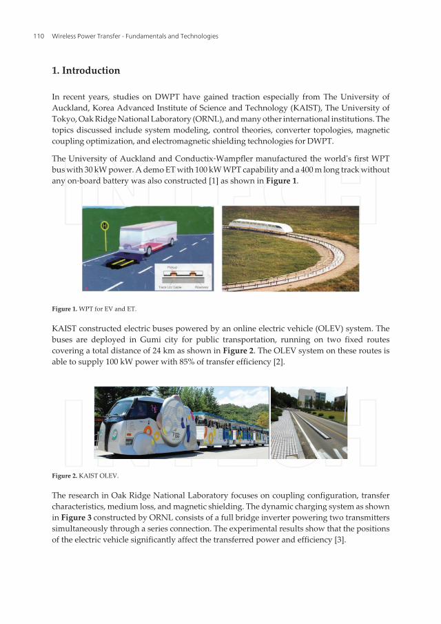
The University of Auckland and Conductix‐Wampfler manufactured the world's first WPTbus with 30 kW power. A demo ET with 100 kW WPT capability and a 400 m long track withoutany on‐board battery was also constructed [1] as shown in Figure 1.
Figure 1. WPT for EV and ET.
KAIST constructed electric buses powered by an online electric vehicle (OLEV) system. Thebuses are deployed in Gumi city for public transportation, running on two fixed routescovering a total distance of 24 km as shown in Figure 2. The OLEV system on these routes isable to supply 100 kW power with 85% of transfer efficiency [2].
Figure 2. KAIST OLEV.
The research in Oak Ridge National Laboratory focuses on coupling configuration, transfercharacteristics, medium loss, and magnetic shielding. The dynamic charging system as shownin Figure 3 constructed by ORNL consists of a full bridge inverter powering two transmitterssimultaneously through a series connection. The experimental results show that the positionsof the electric vehicle significantly affect the transferred power and efficiency [3].
Wireless Power Transfer - Fundamentals and Technologies110
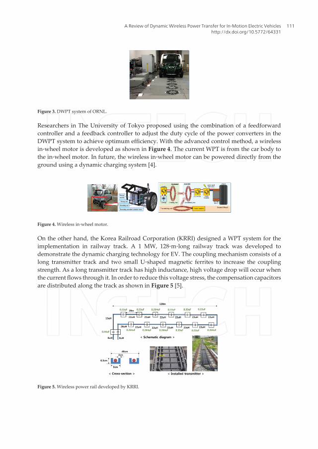
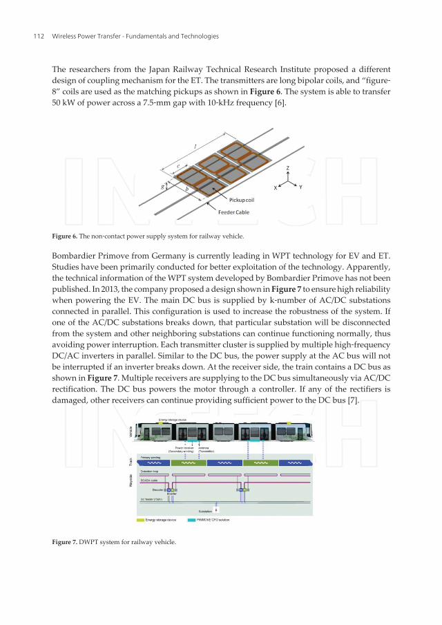
Figure 3. DWPT system of ORNL.
Researchers in The University of Tokyo proposed using the combination of a feedforwardcontroller and a feedback controller to adjust the duty cycle of the power converters in theDWPT system to achieve optimum efficiency. With the advanced control method, a wirelessin‐wheel motor is developed as shown in Figure 4. The current WPT is from the car body tothe in‐wheel motor. In future, the wireless in‐wheel motor can be powered directly from theground using a dynamic charging system [4].
Figure 4. Wireless in‐wheel motor.
On the other hand, the Korea Railroad Corporation (KRRI) designed a WPT system for theimplementation in railway track. A 1 MW, 128‐m‐long railway track was developed todemonstrate the dynamic charging technology for EV. The coupling mechanism consists of along transmitter track and two small U‐shaped magnetic ferrites to increase the couplingstrength. As a long transmitter track has high inductance, high voltage drop will occur whenthe current flows through it. In order to reduce this voltage stress, the compensation capacitorsare distributed along the track as shown in Figure 5 [5].
Figure 5. Wireless power rail developed by KRRI.
A Review of Dynamic Wireless Power Transfer for In‐Motion Electric Vehicleshttp://dx.doi.org/10.5772/64331
111
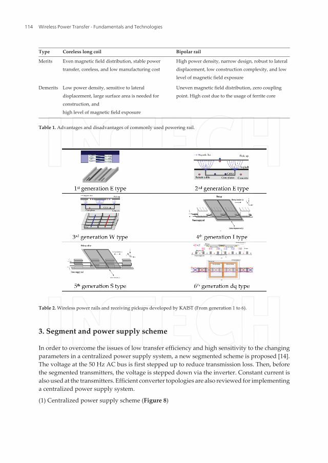
The researchers from the Japan Railway Technical Research Institute proposed a differentdesign of coupling mechanism for the ET. The transmitters are long bipolar coils, and “figure‐8” coils are used as the matching pickups as shown in Figure 6. The system is able to transfer50 kW of power across a 7.5‐mm gap with 10‐kHz frequency [6].
Figure 6. The non‐contact power supply system for railway vehicle.
Bombardier Primove from Germany is currently leading in WPT technology for EV and ET.Studies have been primarily conducted for better exploitation of the technology. Apparently,the technical information of the WPT system developed by Bombardier Primove has not beenpublished. In 2013, the company proposed a design shown in Figure 7 to ensure high reliabilitywhen powering the EV. The main DC bus is supplied by k‐number of AC/DC substationsconnected in parallel. This configuration is used to increase the robustness of the system. Ifone of the AC/DC substations breaks down, that particular substation will be disconnectedfrom the system and other neighboring substations can continue functioning normally, thusavoiding power interruption. Each transmitter cluster is supplied by multiple high‐frequencyDC/AC inverters in parallel. Similar to the DC bus, the power supply at the AC bus will notbe interrupted if an inverter breaks down. At the receiver side, the train contains a DC bus asshown in Figure 7. Multiple receivers are supplying to the DC bus simultaneously via AC/DCrectification. The DC bus powers the motor through a controller. If any of the rectifiers isdamaged, other receivers can continue providing sufficient power to the DC bus [7].
Figure 7. DWPT system for railway vehicle.
Wireless Power Transfer - Fundamentals and Technologies112

The Harbin Institute of Technology demonstrated dynamic charging using segmentedtransmitters with parallel connections to the inverter [8]. At the receiver side, two layers of flatcoils wounded in the same direction are stacked against each other to cancel the points, wheretransferred power is zero, thereby increasing the overall efficiency. Using the decouplingprinciple to design the size and position of the two‐phase coil, the cross‐coupling is cancelledand high efficiency is then achieved at any position [9].
Although several studies have been conducted all over the world yielding exceptional results,factors such as power transfer performance, construction cost, and maintenance cost stillrequire improvement. Other important considerations for practical DWPT implementationinclude high‐power rail, robust control strategies, and EMC.
2. Power rails and pickups
Core‐less rectangular coils and bipolar coils are the two general types of coils used in WPT.The University of Auckland proposed using long rectangular rails to transfer power. A largersurface area for road construction necessitates less amount of power to be transferred persurface area. The design is also sensitive to lateral displacement of the electric vehicles.Moreover, a high level of magnetic field leakage occurs at both sides of the rail [10]. KAISTproposed an improved version by adding a magnetic core with an optimized design. Com‐pared to the transmitter rail proposed by the University of Auckland, the transfer efficiencyand transfer distance are increased. However, the construction cost is also higher.
KAIST presented an advanced coupling mechanism design and optimization technology intheir past research. In 2009, the first‐generation OLEV was successfully produced. An E‐shapedmagnetic core is used as the power transmission rail. The air gap is only 1 cm and the transferefficiency 80% [2]. A U‐shaped transmission rail was also proposed in the same year bysignificantly increasing the transmission gap to 17 cm with an efficiency of 72%. In 2010, askeleton‐type W‐shaped magnetic core is proposed, thus further increasing the transferdistance to 20 cm and efficiency to 83% [2]. From 2011 to 2015, researchers from KAISTdesigned fourth‐generation I‐shaped bipolar rails and fifth‐generation S‐shaped bipolar railswith even larger transfer gap, narrower frame, and higher efficiency [2]. With bipolar rails, themagnetic field path is parallel to the moving direction of the vehicle instead of being orthogonalto the moving direction. The new design is well suited for DWPT due to its advantages suchas high power density, narrow frame, and therefore lower construction complexity, robust tolateral displacement, and lower magnetic field exposure on both sides of the rail [10–12](Tables 1 and 2).
In 2015, KAIST proposed using a dq‐two‐phase transmitter rail for cancelling the zero couplingpoints along the moving direction [13] using the control method which is relatively complex.A double loop control is implemented by detecting the phase of the primary current. Theamplitudes and phases of the d‐q currents are controlled using a phase‐locked loop and DCchopper according to the position of the receiver.
A Review of Dynamic Wireless Power Transfer for In‐Motion Electric Vehicleshttp://dx.doi.org/10.5772/64331
113
Type Coreless long coil Bipolar rail
Merits Even magnetic field distribution, stable powertransfer, coreless, and low manufacturing cost
High power density, narrow design, robust to lateraldisplacement, low construction complexity, and lowlevel of magnetic field exposure
Demerits Low power density, sensitive to lateraldisplacement, large surface area is needed forconstruction, andhigh level of magnetic field exposure
Uneven magnetic field distribution, zero couplingpoint. High cost due to the usage of ferrite core
Table 1. Advantages and disadvantages of commonly used powering rail.
Table 2. Wireless power rails and receiving pickups developed by KAIST (From generation 1 to 6).
3. Segment and power supply scheme
In order to overcome the issues of low transfer efficiency and high sensitivity to the changingparameters in a centralized power supply system, a new segmented scheme is proposed [14].The voltage at the 50 Hz AC bus is first stepped up to reduce transmission loss. Then, beforethe segmented transmitters, the voltage is stepped down via the inverter. Constant current isalso used at the transmitters. Efficient converter topologies are also reviewed for implementinga centralized power supply system.
(1) Centralized power supply scheme (Figure 8)
Wireless Power Transfer - Fundamentals and Technologies114

With the increasing length of the transmitter rail, the bandwidth of the primary side channelbecomes narrower. Therefore, the system is more sensitive to the variations of parameters, andthe robustness is decreased. The controller for the centralized power supply is relatively
a. High requirements of the components due to a single module supporting large power.
b. The whole rail is activated and causes high loss.
c. Low reliability due to any breakdown will affect the whole rail.
d. The efficiency is low when the load is small.
e. High self‐inductance and therefore high voltage across capacitor.
f. Highly sensitive toward the variations in parameters, causing low stability.
Figure 8. Centralized power supply scheme.
Figure 9. Power frequency scheme—segmented rail mode.
(2) Power frequency scheme—segmented rail mode (Figure 9)
The advantages of segmented rails are as follows:
a. Different segments can be turned on at different time periods, decreasing the power loss;
b. Smaller‐sized power converters;
c. Higher reliability, when one of the segments breaks down, other segments will still befunctioning normally;
A Review of Dynamic Wireless Power Transfer for In‐Motion Electric Vehicleshttp://dx.doi.org/10.5772/64331
115

d. Lower self‐inductance, less sensitive to variations in parameters, and therefore increasingthe system stability.
However, segmented rails also have the following disadvantages:
a. High number converters, difficult to control and high maintenance and construction cost;
b. High number of components is required and therefore low reliability of the whole system.
(3) High frequency scheme—segmented rail mode (Figure 10)
With segmented rails and centralized power supply, the advantages of this design are asfollows:
a. Lesser power converter units, easier to maintain;
b. Different segments can be activated at different time periods, lesser power loss;
c. Lower self‐inductance, less sensitive to variations in parameters, increases the systemstability.
Figure 10. High frequency scheme—segmented rail mode.
However, this design has the following disadvantages:
a. When the power supply breaks down, all of the segmented rails will stop functioning,thus lowering the system reliability;
b. High loss in the cable connecting the power supply to the segmented rails;
c. High capacity power supply and therefore large requirements of the components;
(4) High frequency and high voltage scheme and low voltage and constant current rail mode(Figure 11).
Wireless Power Transfer - Fundamentals and Technologies116
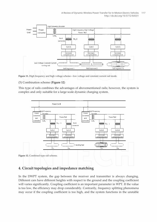
Figure 11. High frequency and high voltage scheme—low voltage and constant current rail mode.
(5) Combination scheme (Figure 12)
This type of rails combines the advantages of abovementioned rails; however, the system iscomplex and only suitable for a large‐scale dynamic charging system.
Figure 12. Combined type rail scheme.
4. Circuit topologies and impedance matching
In the DWPT system, the gap between the receiver and transmitter is always changing.Different cars have different heights with respect to the ground and the coupling coefficientwill varies significantly. Coupling coefficient is an important parameter in WPT. If the valueis too low, the efficiency may drop considerably. Contrarily, frequency splitting phenomenamay occur if the coupling coefficient is too high, and the system functions in the unstable
A Review of Dynamic Wireless Power Transfer for In‐Motion Electric Vehicleshttp://dx.doi.org/10.5772/64331
117

region. Therefore, the circuit topology should be designed to be insensitive to couplingchanges.
In order to achieve a steady power supply with variations in coupling and to increase thesystem stability in the light‐load region, an LCLC topology can be used. The current at theprimary is kept constant and stress on switches is reduced during on‐off. At the receiver side,a parallel‐T configuration can increase the tolerance of the system toward coupling variation.The proposed topology is shown in Figure 13.
Figure 13. Circuit topology of double LCLC.
The transmitter current is written as follows:
0 0( ) / ( )p i r pi U U Lw= - (1)
With λ = L s / L 2 <1 as the load coefficient, the receiver output voltage is as follows:
0o oc p s pU U k L L Il w l= = (2)
The output voltage is 1/λ times the receiver voltage. A step‐up voltage converter is used toprovide sufficient power when coupling is low, therefore increasing the tolerance of the systemagainst lateral displacement.
The voltage ratio and efficiency are given as follows:
2 2 2 20 0
2 2 2 2 2 2 2 2 2 20 0 00
0
0 0
( ) ( ( ))
( ( ))( ( ) ( ( )))s p s
p s
p
s p p s
MR L R r r C M r R r
M R L M r R r L R r C
G
r M r R r
l l w l
w l wh l l w l
+ + + +
= + +
ì
+ + +
=
+ïíïî
(3)
where r0 is the internal resistance of the inverter circuit, rp is the resistance of the transmitter,and rp is the resistance of the receiver.
The power and efficiency curves are given in Figure 14. The efficiency is high at the low‐coupling region which is particularly important for the DWPT application.
As shown by the curves in Figure 15, the efficiency and power are significantly improved fordifferent loads and coupling coefficient compared to series topology.
Wireless Power Transfer - Fundamentals and Technologies118

Figure 14. Efficiency and voltage gain vs. coupling coefficient.
Figure 15. Power and efficiency of the two kinds of structure vs. coupling coefficient.
While designing the circuit of WPT, the compensation is performed under no‐load condition.In normal operating condition, frequency tracking is used to ensure resonance by keeping thesame phase between primary voltage and primary current [12]. Besides, to ensure the EMCand system stability, control is used to achieve constant current. The magnetic field from thetransmitter is in steady state. For example, in the WPT system developed by KAIST, the inputvoltage of the inverter is adjusted using a three‐phase thyristor converter shown in Fig‐ure 16 to achieve constant current at the transmitter.
A Review of Dynamic Wireless Power Transfer for In‐Motion Electric Vehicleshttp://dx.doi.org/10.5772/64331
119
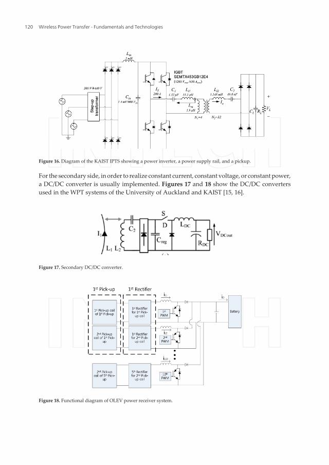
Figure 16. Diagram of the KAIST IPTS showing a power inverter, a power supply rail, and a pickup.
For the secondary side, in order to realize constant current, constant voltage, or constant power,a DC/DC converter is usually implemented. Figures 17 and 18 show the DC/DC convertersused in the WPT systems of the University of Auckland and KAIST [15, 16].
Figure 17. Secondary DC/DC converter.
Figure 18. Functional diagram of OLEV power receiver system.
Wireless Power Transfer - Fundamentals and Technologies120
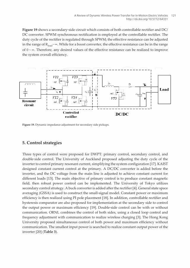
Figure 19 shows a secondary‐side circuit which consists of both controllable rectifier and DC/DC converter. SPWM synchronous rectification is employed at the controllable rectifier. Theduty cycle of the rectifier is regulated through SPWM; the effective resistance can be adjustedin the range of Rload ~∞. While for a boost converter, the effective resistance can be in the rangeof 0∼∞. Therefore, any desired values of the effective resistance can be realized to improvethe system overall efficiency.
Figure 19. Dynamic impedance adjustment for secondary side pickups.
5. Control strategies
Three types of control were proposed for DWPT: primary control, secondary control, anddouble‐side control. The University of Auckland proposed adjusting the duty cycle of theinverter to control primary resonant current, simplifying the system configuration [17]. KAISTdesigned constant current control at the primary. A DC/DC converter is added before theinverter, and the DC voltage from the main line is adjusted to achieve constant current fordifferent loads [13]. The main objective of primary control is to produce constant magneticfield, then robust power control can be implemented. The University of Tokyo utilizessecondary control strategy. A buck converter is added after the rectifier [4]. General state spaceaveraging (GSSA) is used to construct the small‐signal model. Constant power or maximumefficiency is then realized using PI pole placement [18]. In addition, controllable rectifier andhysteresis comparator are also proposed for implementation at the secondary side to controlthe output power or maximum efficiency [19]. Double‐side control can be with or withoutcommunication. ORNL combines the control of both sides, using a closed loop control andfrequency adjustment with communication to realize wireless charging [3]. The Hong KongUniversity proposed simultaneous control of both power and maximum efficiency withoutcommunication. The smallest input power is searched to realize constant output power of theinverter [20] (Table 3).
A Review of Dynamic Wireless Power Transfer for In‐Motion Electric Vehicleshttp://dx.doi.org/10.5772/64331
121
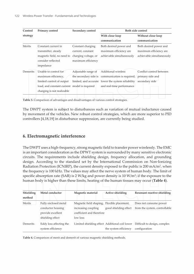
Controlstrategy
Primary control Secondary control Both side control
With close‐loopcommunication
Without close‐loopcommunication
Merits Constant current intransmitter, steadymagnetic field, no need toconsider reflectedimpedance
Constant chargingcurrent, constantcharging voltage, ormaximum efficiency
Both desired power andmaximum efficiency areachievable simultaneously
Both desired power andmaximum efficiency areachievable simultaneously
Demerits Unable to control formaximum efficiency,limited control of outputload, and constant currentcharging is not realizable
Adjustable range ofthe secondary side islimited, and accuratemodel is required
Additional wirelesscommunication is required,lower the system reliabilityand real‐time performance
Conflict control betweenprimary side andsecondary side
Table 3. Comparison of advantages and disadvantages of various control strategies.
The DWPT system is subject to disturbances such as variation of mutual inductance causedby movement of the vehicles. New robust control strategies, which are more superior to PIDcontrollers [4,18,19] in disturbance suppression, are currently being studied.
6. Electromagnetic interference
The DWPT uses a high‐frequency, strong magnetic field to transfer power wirelessly. The EMCis an important consideration as the DPWT system is surrounded by many sensitive electroniccircuits. The requirements include shielding design, frequency allocation, and groundingdesign. According to the standard set by the International Commission on Non‐IonizingRadiation Protection (ICNIRP), the current density exposed to the public is 200 mA/m2, whenthe frequency is 100 kHz. The values may affect the nerve system of human body. The limit ofspecific absorption rate (SAR) is 2 W/kg and power density is 10 W/m2; if the exposure to thehuman body is higher than these limits, heating of the human tissues may occur (Table 4).
Shieldingmethod
Metal conductor Magnetic material Active shielding Resonant reactive shielding
Merits Fully enclosed metalconductor housingprovide excellentshielding effect
Magnetic field shaping,increasing couplingcoefficient and thereforelow loss
Flexible placement,good shielding effect
Does not consume powerfrom the system, controllable
Demerits Eddy loss affecting thesystem efficiency
Limited shielding effect Additional coil lowerthe system efficiency
Difficult to design, complexconfiguration
Table 4. Comparison of merit and demerit of various magnetic shielding methods.
Wireless Power Transfer - Fundamentals and Technologies122

The suppression of the leakage field can be divided into active shielding and passive shielding.In passive shielding, a magnetic path is created using magnetic material or canceling fieldusing a low magnetic permeability metallic conductor [21–23]. The self‐inductance and mutualinductance are increased when using magnetic material. The magnetic flux distribution isimproved due to higher coupling coefficient, and transfer loss is decreased. However, theshielding effect is limited. Metallic shield is widely used in a high‐frequency magnetic field tosuppress electromagnetic interference. Both KAIST and ORNL utilize this kind of shieldingmethod. The advantages include simple design and easy to use. However, metallic shieldingcannot cover the transmitter and receiver completely. The exposed conductor is subject tofriction and eddy current which will increase the heat loss. KAIST proposed a new activeshielding method in 2015. A conventional ferrite plate is embedded in multiple metallic sheetsas shown in Figure 20. Experimental results show that the magnetic interference is effectivelyreduced [24].
Figure 20. Ferrite shielding structure using an embedded metal sheet.
Regarding active shielding, additional coils with or without power supply are implementedat the WPT system to create a cancelling field as shown in Figure 21. Compared to metallicshielding, the space required is smaller.
A Review of Dynamic Wireless Power Transfer for In‐Motion Electric Vehicleshttp://dx.doi.org/10.5772/64331
123

Figure 21. Magnetic field cancellation using a resonant coil.
KAIST published a paper in 2013, proposing an active shielding method using a resonant coil.A switching array is used to change the values of compensated capacitors, thereby controllingthe amplitude and phase of the cancelling field. An experiment was performed using greenpublic transportation [25]. In 2015, an improved version using double loop and phase adjust‐ment to achieve resonance was proposed to achieve an active shielding without power supply.The shielding coils are placed at the side of the coupling mechanism as shown in Figure 22.The current induced by leakage field is then sensed. Magnetic field with the same amplitudebut opposite polarity with the leakage is then created for field cancellation [26].
Figure 22. Resonant reactive power shielding with double coils and four capacitors.
In 2013, ORNL proposed using an aluminum board to reduce electromagnetic interference[27]. As shown in Figure 23, a 1‐mm‐thick aluminum shield is placed above the cables. Themagnetic field measured at the passenger‐side front tire is reduced from 18.72 μT to 3.22 μT.
Figure 23. Suppression of magnetic field after adding aluminum plate and its effect.
Wireless Power Transfer - Fundamentals and Technologies124
7. Conclusions
With the advancement of EV and ET, the significance of DWPT has been consistently growing.Recent developments in DWPT for EV and ET have been presented throughout this chapter.Five different aspects of this technology, such as power rail and pickup design, power supplyschemes, circuit topologies and impedance matching, control strategies, and EMC, arereviewed. Despite obtaining significant results post study in this field, some issues of concernare yet to be resolved. Previous results as well as the challenges in deployment of DWPT inreal application have been highlighted in this chapter.
Author details
Kai Song1*, Kim Ean Koh2, Chunbo Zhu1, Jinhai Jiang1, Chao Wang1 and Xiaoliang Huang2
*Address all correspondence to: [email protected]
1 School of Electrical Engineering, Harbin Institute of Technology, Harbin, China
2 Department of Electrical Engineering, The University of Tokyo, Tokyo, Japan
References
[1] Chen L, Nagendra G.R, Boys J.T, Covic G.A. Double‐Coupled Systems for IPT RoadwayApplications. IEEE Journal of Emerging and Selected Topics in Power Electronics.2015;3(1):37–49. DOI: 10.1109/JESTPE.2014.2325943
[2] Choi S.Y, Gu B.W, Jeong S.Y, Rim C.T. Advances in Wireless Power Transfer Systemsfor Roadway‐Powered Electric Vehicles. IEEE Journal of Emerging and Selected Topicsin Power Electronics. 2015;3(1):18–36. DOI: 10.1109/JESTPE.2014.2343674
[3] Miller J.M, Onar O.C, Chinthavali M. Primary‐Side Power Flow Control of WirelessPower Transfer for Electric Vehicle Charging. IEEE Journal of Emerging and SelectedTopics in Power Electronics. 2015;3(1):147–162. DOI: 10.1109/JESTPE.2014.2382569
[4] Kobayashi D, Imra T, Hori Y. Real‐time coupling coefficient estimation and maximumefficiency control on dynamic wireless power transfer for electric vehicles. In: IEEEWoW 2015 ‐ IEEE PELS Workshop on Emerging Technologies: Wireless Power,Proceedings ; June 5, 2015 ‐ June 6, 2015; Daejeon, Korea. Piscataway, United States:Institute of Electrical and Electronics Engineers Inc.; 2015. p. 1–6. DOI: 10.1109/WoW.2015.7132799
A Review of Dynamic Wireless Power Transfer for In‐Motion Electric Vehicleshttp://dx.doi.org/10.5772/64331
125
[5] Kim J.H, Lee B.S, Lee J.H, Lee S.H, Park C.B, Jung S.M. Development of 1‐MW InductivePower Transfer System for a High‐Speed Train. IEEE Transactions on IndustrialElectronics. 2015;62(10):6242–6250. DOI: 10.1109/TIE.2015.2417122
[6] Ukita K, Kashiwagi T, Sakamoto Y, Sasakawa T. Evaluation of a non‐contact powersupply system with a figure‐of‐eight coil for railway vehicles. In: IEEE WoW 2015 ‐IEEE PELS Workshop on Emerging Technologies: Wireless Power, Proceedings; June5, 2015 ‐ June 6, 2015; Daejeon, Korea. Piscataway, United States: Institute of Electricaland Electronics Engineers Inc.; 2015. p. 1–6. DOI: 10.1109/WoW.2015.7132807
[7] Winter J, Mayer S, Kaimer S, Seitz P, Pagenkopf J, Streit S. Inductive power supply forheavy rail vehicles. In: 2013 3rd International Electric Drives Production Conference,EDPC 2013 ‐ Proceedings; October 29, 2013 ‐ October 30, 2013; Nuremberg, Germa‐ny.Piscataway, United States: IEEE Computer Society; 2013. p. 1–9. DOI: 10.1109/EDPC.2013.6689749
[8] Song K, Zhu C, Li Y, Guo Y, Jiang J, Zhang J. Wireless power transfer technology forelectric vehicle dynamic charging using multi‐parallel primary coils. Zhongguo DianjiGongcheng Xuebao/Proceedings of the Chinese Society of Electrical Engineering.2015;35(17):4445–4453. DOI: 10.13334/j.0258‐8013.pcsee.2015.17.020
[9] Zhu C, Song K, Wei G, Zhang Q. Novel power receiver for dynamic wireless powertransfer system. In: Industrial Electronics Society, IECON 2015 ‐ 41st Annual Confer‐ence of the IEEE; 9 November 2015‐12 November 2015; Yokohama.Piscataway, UnitedStates: Institute of Electrical and Electronics Engineers Inc.; 2015. p. 002247– 002251.DOI: 10.1109/IECON.2015.7392436
[10] Chen L, Nagendra G.R, Boys J.T, Covic G.A. Ultraslim S‐Type Power Supply Rails forRoadway‐Powered Electric Vehicles. IEEE Transactions on Power Electronics.2015;30(11):6456–6468. DOI: 10.1109/TPEL.2015.2444894
[11] Lee W.Y, Huh J, Choi S.Y, Thai X.V, Kim J.H, Al‐Ammar E.A. Finite‐Width MagneticMirror Models of Mono and Dual Coils for Wireless Electric Vehicles. IEEE Transac‐tions on Power Electronics. 2013;28(3):1413–1428. DOI: 10.1109/TPEL.2012.2206404
[12] Huh J, Lee S.W, Lee W.Y, Cho G.H, Rim C.T. Narrow‐Width Inductive Power TransferSystem for Online Electrical Vehicles. IEEE Transactions on Power Electronics.2011;26(12):3666–3679. DOI: 10.1109/TPEL.2011.2160972
[13] Park C, Lee S, Jeong S.Y, Cho G.H, Rim C.T. Uniform Power I‐Type Inductive PowerTransfer System With DQ Power Supply Rails for On‐Line Electric Vehicles. IEEETransactions on Power Electronics. 2015;30(11):6446–6455. DOI: 10.1109/TPEL.2015.2420372
[14] Tian Y. Research on Key Issues of Sectional Track‐Based Wireless Power SupplyTechnology for Electric Vehicles [thesis]. Chongqing, China: Chongqing University;2012.
Wireless Power Transfer - Fundamentals and Technologies126
[15] Keeling N.A, Covic G.A, Boys J.T. A Unity‐Power‐Factor IPT Pickup for High‐PowerApplications. IEEE Transactions on Industrial Electronics. 2010;57(2):744–751. DOI:10.1109/TIE.2009.2027255
[16] Shin J, Shin S, Kim Y, Ahn S, Lee S, Jung G, et al. Design and Implementation of ShapedMagnetic‐Resonance‐Based Wireless Power Transfer System for Roadway‐PoweredMoving Electric Vehicles. IEEE Transactions on Industrial Electronics. 2014;61(3):1179–1192. DOI: 10.1109/TIE.2013.2258294
[17] Abdolkhani A, Hu A.P. Improved autonomous current‐fed push‐pull resonantinverter. Iet Power Electronics. 2014;7(8):2103–2110. DOI: 10.1049/iet‐pel.2013.0749
[18] Hata K, Imura T, Hori Y. Maximum efficiency control of wireless power transfer viamagnetic resonant coupling considering dynamics of DC‐DC converter for movingelectric vehicles. In: Conference Proceedings ‐ IEEE Applied Power ElectronicsConference and Exposition ‐ APEC; March 15, 2015 ‐ March 19, 2015; Charlotte, NC,United states. Piscataway, United States: Institute of Electrical and Electronics Engi‐neers Inc.; 2015. p. 3301–3306. DOI: 10.1109/APEC.2015.7104826
[19] Gunji D, Imura T, Fujimoto H. Envelope model of load voltage on series‐seriescompensated wireless power transfer via magnetic resonance coupling. In: IEEE WoW2015 ‐ IEEE PELS Workshop on Emerging Technologies: Wireless Power, Proceedings;June 5, 2015 ‐ June 6, 2015; Daejeon, Korea. Piscataway, United States: Institute ofElectrical and Electronics Engineers Inc.; 2015. p. 1–6. DOI: 10.1109/WoW.2015.7132853
[20] Zhong W.X, Hui S.Y.R. Maximum Energy Efficiency Tracking for Wireless PowerTransfer Systems. IEEE Transactions on Power Electronics. 2015;30(7):4025‐4034. DOI:10.1109/TPEL.2014.2351496
[21] Kim J, Kim H, Kim M, Ahn S, Kim J, Kim J. Analysis of EMF noise from the receivingcoil topologies for wireless power transfer. In: cccc2012 Asia‐Pacific Symposium onElectromagnetic Compatibility, APEMC 2012 ‐ Proceedings; May 21, 2012 ‐ May 24,2012; Singapore, Singapore. Piscataway, United States: IEEE Computer Society; 2012.p. 645–648. DOI: 10.1109/APEMC.2012.6237964
[22] Kim H, Song C, Kim J, Kim J. Shielded Coil Structure Suppressing Leakage MagneticField from 100W‐Class Wireless Power Transfer System with Higher Efficiency.International Microwave Workshop Series on Innovative Wireless Power Transmis‐sion: Technologies. 2012;16(3):83–86. DOI: 10.1109/IMWS.2012.6215825
[23] Ahn S, Park H.H, Choi C.S, Kim J, Song E, Paek H.B, et al. Reduction of electromagneticfield (EMF) of wireless power transfer system using quadruple coil for laptop appli‐cations. In: 2012 IEEE MTT‐S International Microwave Workshop Series on InnovativeWireless Power Transmission: Technologies, Systems, and Applications, IMWS‐IWPT2012 ‐ Proceedings; May 10, 2012 ‐ May 11, 2012; Kyoto, Japan. Piscataway, UnitedStates: IEEE Computer Society; 2012. p. 65–68. DOI: 10.1109/IMWS.2012.6215821
A Review of Dynamic Wireless Power Transfer for In‐Motion Electric Vehicleshttp://dx.doi.org/10.5772/64331
127
[24] Park H.H, Lwon J.H, Kwak S.I, Ahn S. Magnetic Shielding Analysis of a Ferrite Platewith a Periodic Metal Strip. IEEE Transactions on Magnetics. 2015;51(8):1–8. DOI:10.1109/TMAG.2015.2425796
[25] Kim J, Kim J, Kong S, Kim H, Suh I.S, Suh N.P, et al. Coil Design and Shielding Methodsfor a Magnetic Resonant Wireless Power Transfer System. Proceedings of the IEEE.2013;101(6):1332–1342. DOI: 10.1109/JPROC.2013.2247551
[26] Moon H, Kim S, Park H.H, Ahn S. Design of a Resonant Reactive Shield With DoubleCoils and a Phase Shifter for Wireless Charging of Electric Vehicles. IEEE Transactionson Magnetics. 2015;51(3):1–4. DOI: 10.1109/TMAG.2014.2360701
[27] Ahn S, Park J, Song T, Lee H, Byun J, Kang D, et al. Low frequency electromagneticfield reduction techniques for the On‐Line Electric Vehicle (OLEV). In: IEEE Interna‐tional Symposium on Electromagnetic Compatibility; July 25, 2010 ‐ July 30, 2010; FortLauderdale, FL, United states. Piscataway, United States: Institute of Electrical andElectronics Engineers Inc.; 2010. p. 625–630. DOI: 10.1109/ISEMC.2010.5711349
Wireless Power Transfer - Fundamentals and Technologies128