a review of developments in steel: implications for long
TRANSCRIPT

ORIGINAL ARTICLE
A Review of Developments in Steel: Implications for Long-SpanStructures
Prem Krishna1
Received: 20 November 2020 / Accepted: 25 December 2020 / Published online: 21 January 2021
� The Indian Institute of Metals - IIM 2021
Abstract Historically, iron in different forms has been
known to exist for Architectural and Engineering applica-
tions from early periods of civilisation, but in the modern
context, it would be best to review the growth of steel,
during the last couple of centuries. This paper, first, traces
briefly the developments in steel in terms of its various
aspects, which are relevant to the design of structures. It is
perhaps needless to remind ourselves that humans perpet-
ually endeavour for a better quality of life. To meet the
challenge thus created for providing additional and
improved infrastructure, and, riding on a number of parallel
(or nearly so) developments, the frontiers for Civil and
Structural engineers and architects have moved to horizons
not easy to imagine. One exciting thrust has been towards
increased dimensions, in both height as well as span of
structures, which have touched kilometres from tens of
metres. One of the important factors responsible for the
aforesaid developments is without reservation, the
advancements in steel, and, products based upon it, for
deployment in structures, besides the related aspects of
fabrication, construction and maintenance. There are other
factors too, such as, the growth of electronics which has led
to enormously increased capabilities in computing. Also,
there are the remarkable developments in instrumentation
and robotics as tools in structural engineering. This has led
to a paradigm shift in the scenario for structural analysis,
design and drafting, construction and maintenance. In
traversing the journey above, there are different aspects and
features that have already become convention through
practice and literature, and there is extensive awareness
about them. On the other hand, there are issues and areas of
comparatively new developments about which the aware-
ness is rather limited. The emphasis in this text is largely
on the latter. Since some of these issues can provide for
extensive coverage, the attempt herein is to only bring out
the salient features.
1 Introduction
Quest for better quality of life has been a part of the human
spirit from the very beginning of civilisation, requiring the
virtually never ending need to add to existing infrastructure
as well as to seek all-round improvements in it. A great
deal of this is Civil Infrastructure such as for the habitat,
communication and transportation. Iron and then steel have
played a big part in first enabling the design of smaller
spans and for decorative purposes, and, then in medium
and long-span applications. Steel as a material began to be
used in earnest about two centuries ago, and, finally
matured to be closely entwined in the development of the
modern civil infrastructure elements, such as, long-span
roofs and bridges and tall buildings. If one looks for one
prominent reason for this popular preference for steel, it is
the high strength ratio that it possesses. Besides the
improved strengths in steel, there are the associated
developments in fabrication and construction technologies.
In addition to the growth of steel, the one factor most
responsible for enabling its effective utilisation is the
enormous development in electronics, which in turn has
given an almost unimaginable push to computing capabil-
ities, e-communications, sensor technology, robotics and
developments in the design and drafting scenario.
& Prem Krishna
1 Department of Civil Engineering, IIT Roorkee, Roorkee,
India
123
Trans Indian Inst Met (2021) 74(5):1055–1064
https://doi.org/10.1007/s12666-020-02173-7

2 Developments in steel and associated issues [1–4]
The use of iron in structural applications, though evidenced
even earlier, could be said to have found a place in earnest
in the 1800s, replacing wood and stone to a great extent. A
cast iron bridge across the Severn near Coalbrookdale
opened in the year 1781 is generally regarded as the
world’s first cast-iron bridge. See Fig. 1. The span was
30 m, and it used 386 tons of cast iron. This did influence
bridge design, and few other important iron bridges were
built as a result. However, a flood in 1795 washed away
many bridges on the Severn, but the Iron Bridge survived.
This survival had more influence on bridge design, as did
the completion of Wearmouth Bridge the following year.
Cast iron thus established itself as a viable material for
bridges and a number of bridges followed.
Whereas cast iron has very good strength in compres-
sion, it has limitations in tension and suffers brittle failures.
It thus began to be replaced by wrought iron, which has a
more fibrous character as against the granular one for cast
iron. The use of iron in structures dominated the nineteenth
century in Britain, France, Russia and America. However,
by the end of the century, the use of cast or wrought iron as
a structural material appeared to have been stretched to its
limits and, steel began to be preferred.
In India, the story of use of iron is similar, with some
fascinating examples like the iron pillar in Mehrauli, pur-
ported to have existed from around the fifth century AD.
Likewise, there are also examples of use of cast iron and
wrought iron in small structures. The first landmark
structure using steel was the 655 m long Rabindra setu
(The Howrah bridge). When commissioned in 1943, this
was the third—longest cantilever bridge in the world, and
is currently the sixth longest. See Fig. 2.
The mainstay amongst structural materials for the
industrialised world has been steel, from almost the middle
of the nineteenth century. An alloy with about 0.2 per cent
carbon and the balance mainly iron (with very small
quantities of Manganese and Silicon depending upon the
grade and allowing for some percentage of Sulphur and
Phosphorous), the initiation of the manufacture of steel is
due to Sir Henry Bessemer of England in 1857. The
introduction of the blast furnace changes the earlier process
of producing steel from wrought iron to its manufacture
from a combination of pig iron and carbon, with the pro-
portion of carbon being reduced to the required percentage.
Following this, the processes such as the open-hearth
process and the electric arc furnace were adapted to
steelmaking.
Whereas the leadership in steel development and pro-
duction was with the British in the late nineteenth century,
it passed on to the USA by the end of it. Later during the
century, many other countries such as France, Russia,
Fig. 1 The world’s first iron Bridge opened in 1781 at Coalbrookdale, UK
Fig. 2 The Howrah Bridge, a Balanhed cantilever Bridge over the
Hooghly River in West Bengal, India, commissioned in 1943
123
1056 Trans Indian Inst Met (2021) 74(5):1055–1064

Japan and Germany played a big role. In the current cen-
tury, China is the biggest producer of steel, with nearly
1,000 MT in 2019.
In India, the Bengal Iron Works was founded at Kulti in
Bengal in the year1870 followed by The Tata Iron and
Steel Company (TISCO) which was established by Dorabji
Tata in the year 1907. Later, after its independence from
the British, a government owned company, Hindustan Steel
Limited (HSL), was established in the year 1954 and set up
three steel plants in the 1950s. The Indian steel industry
began expanding into Europe in the twenty-first century,
with Tata Steel buying European steel maker Corus Group,
and with the setting up of ArcelorMittal (based in Lux-
embourg City) having an Indian management. With about
110 MT in 2018, India became the second largest producer
of crude steel.
2.1 Conventional products
The various types of steel products deployed in structural
engineering applications are rolled or drawn sections,
reinforcing bars, prestressing wire, ropes and strands. Till
the 1950s, the commonly available steel structures were
plates and sections with rounded fillets and edges rolled
from mild steel (with strength of 250 MPa). Common
shapes being flats, angles, channels, Is, Ts, etc. While,
further developments have now expanded the range to
parallel flange sections and rectangular tubes, with the
strengths now available in India being of the order of
450 MPa. Japanese had developed 800 MPa steels by the
1960s and used this steel in many bridges, including the
510 m span truss for the Minato Ohashi bridge in the year
1974. The challenge in developing steels for structural
application has not only been the higher strengths but also
improved weldability, toughness, ductility. Other devel-
opments worth mentioning are those of, high performance
steels, steel with high HAZ toughness (which provides
proper fracture toughness in welding), super-high-tension
bolts (SHTB), developed in Japan in 2001.
Furthermore, corrosion has been a concern in the
deployment of steel. The global cost of corrosion in 2013
was considered as US$2.5 trillion, which is equivalent to
3.4% of the global GDP. Therefore, quite naturally there
have been efforts to mitigate the problem with various
types of coatings, and the use of special steels, such as
stainless steel, and weathering steel (COR-TEN steel)
became feasible. Though the use of special steels or pro-
tective measures may be costlier in terms of the initial
estimates, it will be pertinent to look at life cycle costs in
this context.
In reinforcing steels used in reinforced concrete, a sig-
nificant development is that of TMT bars. In India, range of
strengths up to 550 MPa is available. Prestressing wires
and wire ropes and strands, are well known to have higher
strengths of 1,500 MPa or above.
2.2 Wire ropes and strands [4, 5]
Wire ropes and strands are generally part of long-span
roofs and bridges, though also used in guyed towers and
ropeways. Since such long-span structures are still few and
far between, particularly in India, there is comparatively
lesser awareness about ropes and strands too. These are
therefore briefly described in this section.
It is significant that wire ropes and strands for various
applications are of strengths ranging up to 1,800 MPa.
Wire of 1,100 MPa was used in the Brooklyn bridge, which
was the first American suspension bridge to use galvanised
wire, in the year 1883, and, 1,600 MPa in several bridges
from the years 1970 to 1990. Already a mature steel pro-
duct, there have been no dramatic developments recently in
this, except for wire drawing processes. The wires used in
Akashi Kaikyo bridge, Japan were having a strength of
1,800 MPa, and, now steel wires having a strength of
2000 MPa have been developed in Japan [6].
Twisted wire ropes and strands are typically assembled
from thin high strength steel galvanised wires, say, of the
order of 5 mm. Figure 3 shows the cross section through
various types of ropes/strands. Flexibility and extensional
stiffness of a cable are dependent upon the size and number
of wires used and the method of forming it.
Wire ropes have been traditionally used as suspension
bridge hangars, in guyed masts and in suspended roofs.
These are formed by assembling together a required
number of strands and twisting the assembly. Whereas
ropes offer the advantage of flexibility, the size has
essentially to be kept limited. A rope has a more open form
of construction and has a low extensional modulus. Much
of the design technology pertaining to spiral strands is also
common to locked coil ropes since they share the same
form of construction (in concentric helical layers). How-
ever, the use of shaped (interlocking) wires instead of
round wires enables substantially higher fill factors to be
achieved with a proportional increase in mass for a given
cable diameter. These have a greater corrosion resistance,
but are comparatively costlier. Diameter of ropes varies
typically between 10 mm and 50 mm.
As opposed to this, there are parallel wire products,
employed mostly as straight elements such as those in
cable stayed bridges. Thus, one can have a parallel wire
bundle (PWB) in which a number of small size galvanised
wires are assembled straight. The advantage is a higher
breaking strength and extensional modulus. A further
possibility is to produce parallel strand cables (PSC) which
have been used in several cable stayed bridges.
123
Trans Indian Inst Met (2021) 74(5):1055–1064 1057

Suspension bridge cables are usually much larger in
diameter than strands or ropes. These are made up by
‘spinning’ thin zinc-coated wire. The process of ‘spinning’
cables for a bridge may take up to a year or more. In order
to take advantage of factory production, however, it is
possible to put together wire bundles (which can be
transported on reels from the factory). This would be
quicker. The diameters for these cables could be as large as
a meter.
A crucial feature of any type of cable is the means of
attachment to the structure or anchorage. Most factory-
made stays are supplied cut to length and with the end
fittings already attached. The stay manufacturer therefore
designs, fits and warrants the cable end attachments. To be
effective, the end fitting must withstand the breaking force
of the cable without significant yielding and endure
dynamic cycling without risk of fatigue failure and without
inducing fatigue failure of the cable.
The issue of corrosion protection is generally of concern
as mentioned earlier. Steel cables are no exception. In
deciding the protection measures, it is important to keep in
view the extent to which the environment is aggressive—is
it only the ingress of moisture, or industrial gases or coastal
conditions, or a combination thereof! This will determine
the extent and levels of protection required. There are
several types of protection possible. The first kind is gal-
vanic protection for the wire, which involves different
thicknesses of zinc coating. The next is the painting of a
strand or a rope. The third is sheathing. The other is
grouting an outer protective sleeve.
2.3 Fabrication
A major factor in enabling the utilisation of developments
in steel has been the simultaneous growth in fabrication
and construction techniques and equipment. Thus, for
example, there is the automation in cutting and welding of
structural elements and jointing. Similarly, the availability
and large scale use of High Strength Friction Grip bolts
(HSFG) to replace riveting has brought about a sea change
in the construction of large steel structures in terms of
greater convenience and speed. Likewise, it has increas-
ingly become possible to lift/transport larger/heavier fab-
ricated modules. The advent of robotics offers a potential
for in-shop fabrication as well for tackling fabrication
problems in terrains where access is difficult.
3 Design and construction
There are many aspects of steel as a construction material,
which lead to its application in modern steel structures,
often of large dimensions. These are mentioned below.
However, these large span, lighter weight and flexible
structures have certain features and challenges for the
designer. These issues are also addressed briefly in this
section.
3.1 Benefits of using steel
Steel as a construction material offers greater adaptability,
easier modifications, repairs, retrofitting, economy—cer-
tainly on life cycle basis, speedier construction, well
defined mechanical properties, and higher strength–weight
ratio. If amongst the other factors, one sees benefits of
higher strength–weight ratio alone, these are reduced dead
weight, saving in usable space, lighter load on foundations.
As a structure gets taller or longer in span, the live load to
dead load stress ratio becomes smaller. This implies that
the structural material begins to be utilised increasingly by
its own dead weight. It is therefore imperative to use
materials with high strength weight ratios to keep the dead
weight to a minimum. In the context of a tall building, the
column cross sections will become un-manageable with
materials of low strength, and useful floor space will be
wasted besides increasing the load on the foundations.
With the use of steels, this problem is overcome effectively
and is even more so if higher strength steels are used. In the
case of large covered spaces using arches or space frames,
the same logic is applicable. The deployment of suspended/
tension systems further enhances this advantage. However,
one needs to be cautioned that unduly reduced mass of the
structural elements, or increased slenderness, can give rise
to the structure becoming prone to unacceptable instability
problems—aerodynamic or otherwise. Some typical rela-
tive strength–weight ratios are given below:
Fig. 3 Cross section through
various types of ropes/strands
123
1058 Trans Indian Inst Met (2021) 74(5):1055–1064
Mild steel 30
Higher strength structural steel (800 Mpa) 100
High strength wire steel (1800 Mpa) 225
Aluminium alloys 90
Medium strength concrete (M30) 12
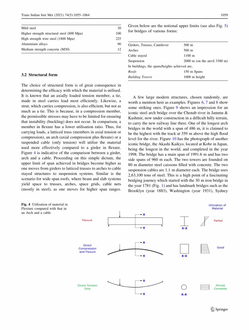
3.2 Structural form
The choice of structural form is of great consequence in
determining the efficacy with which the material is utilised.
It is known that an axially loaded tension member, a tie,
made in steel carries load most efficiently. Likewise, a
strut, which carries compression, is also efficient, but not as
much as a tie. This is because, in a compression member,
the permissible stresses may have to be limited for ensuring
that instability (buckling) does not occur. In comparison, a
member in flexure has a lower utilisation ratio. Thus, for
carrying loads, a latticed truss (members in axial tension or
compression), an arch (axial compression plus flexure) or a
suspended cable (only tension) will utilise the material
used more effectively compared to a girder in flexure.
Figure 4 is indicative of the comparison between a girder,
arch and a cable. Proceeding on this simple dictum, the
upper limit of span achieved in bridges become higher as
one moves from girders to latticed trusses to arches to cable
stayed structures to suspension systems. Similar is the
scenario for wide span roofs, where beam and slab systems
yield space to trusses, arches, space grids, cable nets
(mostly in steel), as one moves for higher span ranges.
Given below are the notional upper limits (see also Fig. 5)
for bridges of various forms:
Girders, Trusses, Cantilever 500 m
Arches 500 m
Cable stayed 1100 m
Suspension 2000 m (on the anvil 3300 m)
In buildings, the spans/heights achieved are,
Roofs 150 m Spans
Building Towers 1000 m height
A few large modern structures, chosen randomly, are
worth a mention here as examples. Figures 6, 7 and 8 show
some striking ones. Figure 9 shows an impression for an
iconic steel arch bridge over the Chenab river in Jammu &
Kashmir, now under construction in a difficult hilly terrain,
to carry the new railway line there. One of the longest arch
bridges in the world with a span of 486 m, it is claimed to
be the highest with the track at 359 m above the high flood
level for the river. Figure 10 has the photograph of another
iconic bridge, the Akashi Kaikyo, located at Kobe in Japan,
being the longest in the world, and completed in the year
1998. The bridge has a main span of 1991.6 m and has two
side spans of 960 m each. The two towers are founded on
80 m diameter steel caissons filled with concrete. The two
suspension cables are 1.1 m diameter each. The bridge uses
2,63,100 tons of steel. This is a high point of a fascinating
bridging journey which started with the 30 m iron bridge in
the year 1781 (Fig. 1) and has landmark bridges such as the
Brooklyn (year 1883), Washington (year 1931), Sydney
Fig. 4 Utilisation of material in
Flexture compared with that in
an Arch and a cable
123
Trans Indian Inst Met (2021) 74(5):1055–1064 1059

Harbour (year 1932), Golden Gate (year 1937), Severn
(year 1966).
3.3 Analysis
The routine aspects of the analysis and design of steel
structures are generally well understood. Although too well
known to be pointed out, ensuring stability of compression
elements is a prime design issue. However, as spans,
heights or complexities of structures become greater, there
are several challenges related to analysis and design. A
brief discussion on these follows.
Fig. 5 National upper limits for different forms of Bridges
Fig. 6 L&T Steel Melting Shop, Hazira, Gujarat, 2011 (Area
covered: 70,000 m2. Plan Dimension: 86m–116m 9 750 m. Steel
used: 20,000 t. Cost of steelwork: Rs. 220 Crores) [Courtesy: Institute
for steel Development and Growth]
Fig. 7 GMS Grande Palladium, Kalina, Mumbai, 2010 (Built area:
18,000 m2. Cost: Rs. 60 Crores) [6] [Courtesy: Institute for Steel
Development andGrowth]
Fig. 8 TCS Technopark Project: Phase-I, Chennai 2009 (Architec-
ture: Butterfly/Dragon Engineering Buildings: 21 m 9 85m (3 Nos.).
Central spine: 345 m long, 45 m high. Steel used: 28000 t. Cost of
steelwork: Rs. 172 Crores. Number of steel member elements running
into lacs) [Courtesy: Institute for SteelDevelopment and Growth]
Fig. 9 A view for the Railway Bridge under construction over the
River Chenab in J&K (personal communication from Konkan
Railway Corporation Limited)
123
1060 Trans Indian Inst Met (2021) 74(5):1055–1064

3.3.1 Indeterminacy
Steel structures of the kind in focus in this paper are all by
and large indeterminate, and, usually the degree of inde-
terminacy is large too. The examples are those of multi-
storeyed multi-bay frame works for buildings, space frames
and grids, cable roof networks, cable stayed and suspension
bridges. The response of these structural systems to loading
is also often nonlinear (see next). However, the develop-
ments in digital computing capabilities since the 1950s,
which have continued to grow beyond imagination during
the last few decades (a palm held calculator being more
powerful than one housed in a big room amongst the early
versions), have meant that it is now an amenable exercise
to analyse a structure of 1000 (plus) degrees of indeter-
minacy for static or dynamic effects, even taking account
of nonlinearity, if, applicable. Thus, an entire range of
software packages, dealing with analysis to drafting and
automation in fabrication, have provided a rich repertoire
for the engineer and the architect.
This is not to say that such challenging steel structures
were not constructed before the computer era. In fact, some
of the most fascinating large span suspension bridges were
constructed in the period between 1880 and 1940, besides
the Empire State building, Rabindra setu, the Eiffel tower
and so on. However, all this was based on hand calcula-
tions with approximate theories.
3.3.2 Nonlinearity
In most structures, whether in steel or another material, the
relationship between applied load and the response of the
structure thereto can be represented by a straight line.
However, for tall or wide span structures, particularly using
steel, the relationship quoted above can be nonlinear. As
indicated in Fig. 11 and described as under, there are
several reasons for this.
1. These large structures can be flexible and undergo
large deformations, thus violating the assumption that
analysis can be based on the initial geometry of the
structure. The nonlinearity thus caused is termed as
’geometric’. This is common in cable supported roof or
bridge structures.
2. Another factor leading to a nonlinear response is what
is commonly called the ‘P-delta’ effect in members
where axial compressive force interacts with flexure of
the member. This is a distinct possibility in such cases
as self-supporting towers, bridge pylons, girders in a
cable stayed bridge, curvilinear supporting elements of
a cable or a membrane roof structure.
3. Slender members under axial compressive forces are
liable to undergo buckling and behave nonlinearly in
the post buckling range. Furthermore, the buckling of
an element, which is a sudden phenomenon, can render
a determinate structure deficient, whereas an indeter-
minate structure will experience a sudden change in its
stiffness.
4. A feature specific to cable stays can be termed as the
‘sag’ effect, whereby the extensional stiffness of the
stay varies nonlinearly with its sag (or tension). This is
similar to the ‘P-delta’ effect except that the force is
tensile rather than compressive.
5. If the material constituting one or more elements in a
structure has a nonlinear stress–strain relationship,
partly or wholly through the stress range, the structure
response will become nonlinear to applied loading. For
steel structures, this is not an issue, except if a part or
whole of the structure enters into the post-elastic
range. Twisted wire ropes do exhibit a degree of
nonlinearity in the initial stress range, because of the
way these are constructed.
3.3.3 Wind effects
Steel structures are lighter than the stone, masonry or the
concrete ones. For these, generally the wind loading may
be expected to govern rather than the seismic load, from
amongst the two occasional loads. For the larger span or
taller buildings, roofs and bridges, which fall under the
category of ‘wind-sensitive’ structures, this is certainly
true.
The last 100 years, or so, have seen the use of these
structures increasingly, and, thus also an increase in wind
engineering related development. The features of wind
loading and related design issues are briefly addressed
below.
Wind is a randomly varying dynamic natural phe-
nomenon. This, when obstructed by a structure, causes
pressures upon its surface, which are essentially dynamic,
Fig. 10 The Akashi Kaikyo suspension Bridge-longest in the world
123
Trans Indian Inst Met (2021) 74(5):1055–1064 1061

because of the inherent nature of wind. For comparatively
rigid or stocky structures, these dynamic effects can be
treated as being quasi-static for simplification in the design
of the structure. However, for the larger and more flexible
ones, particularly in focus in this paper, aerodynamic
effects have to be taken into account. This aspect is one of
the more important challenges in the design of modern
steel structure design. The related features are brought out
for flexible, roofs, buildings and bridges.
3.3.4 Tall Buildings and Towers
Tall structures, particularly those made primarily in steel,
are essentially wind-sensitive and evoke an aerodynamic
response. In this category, one can place, buildings, bridge
pylons, towers-latticed or otherwise. There are specifically
two ways in which these structures are affected due to wind
loading. The first is the wind-induced fluctuating vibration,
called buffeting, which effects the structure along the
direction of the wind. The other is the across-wind oscil-
lation due to shedding of vortices, which create an across-
wind
Pulsating force: Whereas the along-wind effect is
monotonic, the across-wind effect is akin to a pendulum
vibrating across the vertical axis of the tower. This often is
the more important problem for the designer. While the
basic requirement is to ensure safety and limit the dis-
placements, control of accelerations is another objective
for the comfort of occupants in buildings.
3.3.5 Wide-Span Roofs
There are several reasons due to which, loads and effects of
wind have an important place in as far as steel or cable
roofs are concerned. These roofs have a unique geometrical
shape (see for example Figs. 7 and 8), and the wind load
coefficients are not easily available. It may often become
necessary to make a wind tunnel model study to obtain this
information. It is pertinent to point out in this context that,
particularly in fabric roofs, the deformations of the mem-
brane would modify the pressures, and there is as yet
hardly any work done to test models taking into account the
roof membrane flexibility, in the wind tunnel. Another
aspect that needs to be highlighted is that, wind causes non-
uniform pressures on cable roof surfaces [7] (see Figs. 12
and 13) and this may lead to large displacement in such
flexible roofs.
Aerodynamic oscillations are a distinct possibility for
these flexible roofing systems, though there does not appear
on record any indications of serious distress on this
Fig. 11 Different sources of
nonlinear response of structures
123
1062 Trans Indian Inst Met (2021) 74(5):1055–1064

account. Amongst the Tension structures under discussion,
cable bridges are far more of an issue from the wind
engineering standpoint and are addressed below.
3.3.6 Bridges
Usually, wind loading takes on important proportions for
medium span bridges, such as those over 200 m, but
becomes a serious design concern for 400 m or over. While
this space is taken up by a few arches, it is mostly the cable
stayed and suspension bridges. The dynamic behaviour of
the bridge under the action of wind loads is dependent upon
the flow; particularly in terms of the turbulence charac-
teristics, angle of attack, and the structural as well as
aerodynamic characteristics—the mass, stiffness, fre-
quency, geometrical shape and damping. It is noteworthy
that the site peculiarities can often manifest themselves into
a dramatic influence on the aerodynamic effect on such
bridges. For cable bridges, while pylons have issues such as
those mentioned earlier, the aerodynamics of decks is of
primary concern, and there are some aspects of cable stays
need to be addressed.
Deck: Various forms of aerodynamic response for the
deck can be described as buffeting, vortex induced oscil-
lations, and self-excited oscillations such as in vertical
bending, torsional bending, galloping in towers, or, flutter.
Initially, cable bridges used stiffening girders of trusses
along with a concrete or a steel deck. Collapse of the
Tacoma Narrows suspension bridge led to the idea of using
box girder decks to minimise wind loading, as well as to
meet the requirements of adequate torsional stiffness. It is
noteworthy that split boxes were found to be superior to
single boxes for aerodynamic stability, which also led to
the idea of using multiple boxes connected through cross
girders. Figure 14 shows one such concept for a long-span
suspension bridge [8]. One of the major design concerns in
this respect has been to choose a deck and stiffening system
to raise the critical wind speed for the initiation of flutter
above the design wind speed, by introducing adequate
stiffness. It is also possible to use fairings on the edges of
the deck along parts of its length, in order to reduce its
oscillatory motion. It is being investigated too whether the
use of passive controls such as the use of control surfaces
or ‘wings’, or, pendulums can be of advantage in sup-
pressing deck oscillations.
Cables: Cables are employed in suspension bridges as
‘main’ cable and hangers and in cable stayed bridges as
‘stays’. For suspension bridges, cables are quite massive,
and do not generally have an aerodynamic problem. These
being tied up with the deck and the pylon tops, participate
in overall bridge vibrations. The hangers often experience
‘singing’ which is an across-wind vibration of the hanger.
The same kind of vibration is possible in cable stays. As
stays become longer, the problem of rain–wind-induced
vibrations also becomes a possibility. Furthermore, hangers
and stays may often be provided in pairs, or may even
consist of 4 small size ropes or strands. In such cases,
‘wake’-induced across-wind oscillations may occur. To
overcome these problems, provision of auxiliary cables for
long stays, use of damping devices to control ‘singing’ and
use of surface features to take care of ‘rain–wind’ and other
oscillation problems are resorted to.
4 Conclusions
Developments in Steel as a construction material, and, the
allied issues of fabrication, construction and maintenance
in the past 200 years, have been largely responsible for its
deployment in modern structures with large dimensions—
both height as well as spans—such as roofs, building
towers and bridges. Thus, a great fillip has been made in
meeting the challenge of adding good quality infrastruc-
ture. Another factor most responsible in the effective util-
isation of the latest steel products is the enormous growth
Fig. 12 The Shell shaped Yoyogi National Gymnasium for the
Swimming pool, Tokyo Olypics, 1964, designed by Kenzo Tange
Fig. 13 Wind pressure distribution over the roof in Fig. 12 [7]
123
Trans Indian Inst Met (2021) 74(5):1055–1064 1063

in electronics and its applications in computing, sensors,
communication and robotics. India is catching up with the
rest of the world surely though slowly.
Acknowledgements The author thanks Er. Amitabha Ghoshal and
Er. Alok Bhowmick, two eminent structural engineers, for their time
in reading through the script and for their valuable inputs. Likewise,
thanks are due to Professors Toshio Miyata and Yukio Tamura for
information about the Akashi Kaikyo suspension bridge. Permission
by Institute for Steel Development and Growth for use of technical
material from their archives is thankfully acknowledged. The author
is thankful to Mrs. Pratigya Laur helping with the script and
illustrations.
References
1. Van Dyke S, The History of Wrought and Cast Iron, Masters
Thesis, The University of Tennessee, May 2004.
2. Delony E, The Golden Age of the Iron Bridge, Invention andTechnology (1994).
3. The Indian Steel Industry: Growth, Challenges and Digital
Disruption, Indian Steel Association (2019).
4. Miki C, Development of High Strength and High Performance
Steels and Their Use in Bridge Structures, in Proceedings of theInternational Seminar on Long-Span Bridges and Aerodynamics,T. Miyata, et al. (Eds.), Springer (1999).
5. Krishna P, J Constr Steel Res 57 (2001) 1123–1140
6. Tarui T, Nishida S, Yoshie A, Ohba H, Asano Y, Ochiai I,
Takahashi T, Wire Rod for 2,000 MPa Galvanised Wire and
2,300 MPa PC Strand, Nippon Steel Technical Report, No. 80,
pp. 44–49 (1999).
7. Krishna P, Cable Suspended Roofs, McGraw-Hill, New York,
1978. Second edition 2013.
8. Diana G, Bruni S, Cigada A, Collina A, Turbulence Effects on
Flutter Velocity in Long Span Suspension Bridges. J Wind Eng IndAerodyn 48 (1993) 329.
Publisher’s Note Springer Nature remains neutral with regard to
jurisdictional claims in published maps and institutional affiliations.
Fig. 14 Cross section of a
proposed Deck for the Messina
Straits suspension Bridge [G.
Diana et al. Ref. 7]
123
1064 Trans Indian Inst Met (2021) 74(5):1055–1064