a research method for shock loadings on rotation isolator ... · builds an integrated model...
TRANSCRIPT

Abstract—This paper proposes a simulation method in order
to analyze the dynamic response of the components in
ammunition to the sever shock loadings during the process of
launch accurately It is the implicit-explicit sequential finite
element dynamic analysis to research the shock loadings on the
rotation isolator used in Course Correcting Fuse. The paper
builds an integrated model containing isolator, projectile, gun
tube and breech. The simulation process is finished by mesh
generation, setting the loads boundary conditions, contact
definition and output control. At first, gun tube’s deformation
due to gravity at 52 degrees quadrant elevation was acquired
from the implicit analysis. Then the displacement and velocity of
projectile are obtained to verify the gun tube’s deformation
through the explicit analysis. The bearings’ axial and transverse
acceleration in the isolator are depicted. The results of the
research indicate that the gun tube deformation, base pressure
and pressure dissipation at the muzzle exit are main factors to
influence the shock loadings on the isolator. The projectile’s
accelerated spin and the collision with the barrel inside wall
produce centrifugal inertia force and gyroscopic couple which
influence the transverse shock loadings. In addition to this, a
calculation method is proposed to work out the maximum
contact stress of the bearing’s components. The method is
combined with the bearings’ components maximal contact stress
in the process of simulation. The results of the research prove
that the calculation method is correct and credible. The research
conclusions provide some reference for the structural design of
Course Correcting Fuse.
Index Terms—rotation isolator, implicit-explicit sequential
finite element analysis, shock loadings, bearing
I. INTRODUCTION
mart artillery munitions, equipped with guidance and
control system, which contain kinds of sophisticated
embedded electronic system and electric actuating
mechanism such as machine and canard, have been developed
by the US Army during the last forty years. In 2006, the
operating theory of Precision Guidance Kit showed in Fig.1
This work is supported by National Deference Pre-Research Foundation
of China.
Jianghai Hui is with Shijiazhuang Mechanical Engineering College,
No.97 Heping West Road, Shijiazhuang, Hebei, 050003, China
(corresponding author to provide phone: 18330170253; e-mail:
Min Gao is with Shijiazhuang Mechanical Engineering College, No.97
Heping West Road, Shijiazhuang, Hebei, 050003, China (e-mail:
Yi Wang is with the Shijiazhuang Mechanical Engineering College,
No.97 Heping West Road, Shijiazhuang, Hebei, 050003, China (e-mail:
Cheng Cheng is with the Shijiazhuang Mechanical Engineering College,
No.97 Heping West Road, Shijiazhuang, Hebei, 050003, China (e-mail:
was firstly introduced by United States in their patent,
two-dimension guidance of projectile fixed wings. In this
paper, the Course Correcting Fuse, belongs to a kind of
Precision Guidance Kit is regarded as the study object. The
electricity devices in the fuse which is powered by power
source control the spin of the fixed wings tied to the fuse.
Therefore, it can change the aerodynamic characteristics of
the projectile and make precision guidance for uncontrolled
projectile come true. The fuse screws to the projectile through
the rotation isolator, therefore, rotational movement relative
to projectile can be realized by it. In gun-launched projectiles,
large shock loadings both in axis and transverse direction
generated during a launch process tend to cause the
sophisticated devices to fail. It is the reason to improve the
operating performance, accurate identifications for stress
circumstance during then launch and reduction of the shock
loadings applied to the components in the fuse are the critical
issue must be taken into account.
Fig. 1. Precision Guidance Kit
It is a complex dynamic process that the projectile pushed
by the gas at high pressure from the propellant moves from the
breech to the muzzle of the gun barrel with high speed rotation
accelerated to 18000 rpm at the muzzle exit by interaction of
rifling and band. The shock loadings applied to the system,
and devices are difficult to be measured and the dynamic
response to shock cannot be analyzed accurately.
Earlier in the study, the researchers developed the model in
a simple way and conducted simplified experiments to
analyze the dynamic process during projectile launch.
Simkins et al. predicted resonant condition of the projectile
and gun tube through dynamic experimental analysis [1]. A
two-dimensional quasi-static model of a training projectile
was developed by Hollis and with this model the projectile
was redesigned to reduce stresses [2]. Hopkins and Wilkerson
A Research Method for Shock Loadings on
Rotation Isolator used in Course Correcting Fuse
Jianghai Hui, Min Gao, Yi Wang, Cheng Cheng
S
Engineering Letters, 26:1, EL_26_1_05
(Advance online publication: 10 February 2018)
______________________________________________________________________________________

developed an axisymmetric transient FEM of the M256 gun
system to explain the experimental results on reducing the
dynamic motion during firing [3].
As research continued, experimental test is too expensive
and time-consuming to conduct and there are some
uncontrollable factors during test leading to failure of
demonstrating theoretical and experiential analysis. However,
the researchers in this field gradually adopted numerical
models such as finite-element models like the flight vehicle
[4], [5]. Engineers and researchers in US Army performed
static and quasi-static analysis in centrifuge tests with the use
of pressure-time curves and peak acceleration value to design
the components and improve their overloading-resistibility
[6]. They once conducted three types of tests to find failures
and build reliability of Systems, subsystems, and components
in projectile [24]. Kessler and Spearing designed and tested
the aft section of a kind of autonomous flying vehicle which
was subjected to high impulsive inertial loads by developing a
quasi-dynamic FEM of the aft section [7]. Chowdhury et al.
conducted the parameters study in identifying sensitive
factors affecting the muzzle exit dynamics of projectile with
an integrity model including balloting, spinning and gun
mount position. Then they determined the resulting vibrations
of a projectile through developing a 3D explicit dynamic
finite element model [8]. Petersen et al. developed the FEM
and conducted the simulation by SIMBAD and Abaqus to
compare with experimental data, including position,
acceleration, and strain of a projectile during firing to
improve correlation between dynamics modeling and test data.
[9]. To better understand how shocks send to electronic
boards and ways to mitigate shocks, Chakka et al. created a
3D FEM and illustrated the dynamic response of the devices
in the projectile. [10]. Tzeng et al. regarded the rail gun as a
beam with an elastic foundation, and they created a transient 4th
differential equation based on the result data from the analysis
of dynamic behavior during launching to describe the structure
response of the gun. However, they neglected the flexibility of
the gun. [11]. Laughlin analyzed the dynamic behavior of a
gun-launched projectile through a 3D explicit FEM and
studied the effect of geometry on the intensity of transverse
acceleration caused the electronic components failure. [12].
Somasundaram created a projectile model which could mimic
an actual projectile to study the effect of the tightening
preload torque on accelerations and frequencies of
components on boards [13]. Reinhardt et al. found that there
was a significant reduction in accuracy when solder is not
included in the model developed with finite element method
[14]. With explicit axisymmetric Lagrangian-Eulerian Finite
Element simulation adopted, Yin et al. obtained the dynamic
characteristics of the precision-guided projectiles during
launch process and investigated the whole process of firing to
observe the local and global feature of setback, set forward
pressure and acceleration histories [15]. The results indicated
and described the effects of different media including the
propellant, projectile, confined volume and free space.
Kuncham from University of Nevada presents the effect of
shock and the structural response of the electronic
components within the projectile and results are verified by
experimental and modal analysis [23].
Based on the response of devices with in the projectile and
the interaction between the gun tube and projectile during
launch, it is also important to find schemes to reduce the
shocks on them. Cui, et al. analyzed the anti-shock
performance of the electronic devices in the electromagnetic
launched projectile with establishing a mathematical model of
the two-phase pulsed alternator. They also used the finite
analysis software to create finite element model including
printed circuit and other components [21]. With adopting
optimization algorithm, some researchers obtained the
optimum parameter design about performance indexes [16].
The electronic devices always failed due to shocks during
launch. With the theory of wavelet and the means of FEA,
Heaslip and Punch reduced the failure of devices in projectile
with foam materials. However, this method may affect the
upgrade and replacement for the system. [6]. Chakka et al.
used carbon fibers embedded in an epoxy matrix and studied
the effect of reducing the transmitted shocks during launch
with the composite supporting plate by varying the thickness
of it. [10]. Somasundaram adopted stiffeners and dampers to
protect electronic devices in the projectile. However, when
the frequency of acceleration exceeds 5,000 Hz, they
discovered that it cannot protect the electronic devices [13].
Sueki et al. created finite element model of a layered
cylindrical structure and simulated to verify that the effect of
impedance mismatch in axial acceleration response under
shock loadings [17]. Researchers tend to acquire the correct
results with using precise model, which also have good
agreement with actual situation. However, aiming at most
complexity of problems, researchers and engineers
oversimplified the model of projectile and its devices or
components. A report of process Excalibur and SADARM
smart projectiles presented that the models in design are too
simplified to get the dynamic response accurately. In addition,
the oversimplified models generat the failures of devices in
the projectile during verification testing [10], [18]. Engineers
researched for traditional existing models based on
quasi-static conditions, thus using the results from the models
to correct boundary conditions [4], [5]. The reasons for the
failure of onboard-embedded electronic cannot be accurately
predicted by the quasi-static analysis are following illustrated:
First, most structures fail after moving out of the muzzle.
However, many researchers always ignore the effect of shock
loadings at the muzzle exit, and it is too complex for them to
analyze. Second, researchers are likely to neglect transverse
shock loadings, which generate the high-frequency vibrations
of structure and cause failure [5], [10], [14], [18].
In addition, the sudden decrease in loading resulted from
the gas expand freely at the muzzle exit caused the oscillation
of the projectile at high frequencies around its center of
gravity [4], [18]. And researchers always ignore the nonlinear
transient conditions resulted from the interaction between the
gas and projectile [19]. Reference [15] examined that the
reflected waves as well as spring back of the precision-guided
projectiles resulted from these local oscillations as it moves
out of the muzzle. Numerous failures of sensitive equipment
within the munitions programs like the US Army’s Excalibur
and SADARM were experienced due to shock from muzzle
exit transient. The shocks transmitted to the embedded
electronic system resulted in the great possibility of failure
rather than the maximum axial acceleration. The transverse
Engineering Letters, 26:1, EL_26_1_05
(Advance online publication: 10 February 2018)
______________________________________________________________________________________

movement of the projectile is no longer constrained by the
barrel wall, so it was not allowed to neglect the balloting
acceleration in the set forward region [20]. Besides, US Army
Researchers developed deterministic barrel model that
possesses both vertical and lateral deviations from centerline
in accordance with measurement data, and simulated
comprehensive barrel centerline variations for the
investigation of projectile balloting motions by a novel
approach [22].
This paper conducts the implicit-explicit sequential
finite-element analysis in order to research dynamic response
of the rotation isolator used in the Course Correcting Fuse to
the shock loadings during launch. At first, we create an
integrated model containing gun tube, breech, projectile and
the isolator in the Course Correcting Fuse. Then, the
pre-processing, including modeling, element type, material,
mesh, boundary condition, solution controlling will be
described. Next, the dynamic response of the bearings in the
isolator to shock loadings will be analyzed. Finally, we
calculated the maximum contact stress of the important
components in the fuse through Hertz theory.
The remainder of this paper is organized as follows: Sect.2
presents the description of the integrated model, including
gun tube, breech, projectile and rotation isolator in the Course
Correcting Fuse. Sect.3 describes the pre-processing of
simulation. Sect.4 reports the simulation results that address
the characteristics of dynamic response of the bearings in
isolator to the axial and transverse shocks, and proposes the
calculation method combined with the simulating in previous
section to work out the maximum contact stress of bearings in
based on Hertz theory. In sect.5, we conclude the paper.
II. MODEL DESRIPTION
It can be seen from Fig.2 shows that the Course Correcting
Fuse is screwed onto the projectile. Inside the rotation isolator,
there is a permanent magnet machine served as a power
source, while it is also used to drive and control relative
rotation between the fixed canard and projectile. Rotation
isolator is comprised of bearings, housing and shaft, which
was simplified by eliminating exact details in modeling. The
fixed canard mentioned above is screwed onto the shaft and
electricity components occupying inside fuse were simplified
as the payload. There are three bearings, two deep groove ball
bearings ( hereinafter referred to as the ball bearing ) and one
axial needle roller thrust bearing ( hereinafter referred to as
the thrust bearing ), inside the isolator connecting the housing
and shaft to realize the relative rotation between projectile
and canard. The projectile and fuse are subjected to axial and
transverse shock loadings exceed 15,000 G’s during artillery
firing within a few milliseconds. Plastic deformation or cracks
on the contacting surfaces between raceway grooves and
rollers occurred under shock loadings, locating the cause that
failure of the fuse during flight.
Based on the description above, the structure of isolator is
designed as Fig.3 shows. The thrust bearing is adopted to
improve the capacity of shock resistant for isolator. It can
experience the majority of shock loadings thus preventing the
two ball bearings from plastic deformation or cracks.
According to manual data, the rated static load of the thrust
bearing is about 20,000 N. To ensure operating reliability
during launch and decrease the adverse effect on the isolator
and other devices, the buffers are added between the thrust
bearing and the housing to isolate the shock loadings
produced by the propellant explosion. The influence of the
canard and electronic components cannot be neglected, so a
1.3-pound mass payload was attached to the shaft.
As mentioned in sect.1, the transverse acceleration should
not be neglected. The manufacturing imperfections and gas
leakage between the projectile and gun barrel cause the
projectile to be subjected to transverse shock loadings, known
as balloting, inducing continual violent impacts with the
barrel’s inside wall. Balloting is the transverse motion of a
projectile inside a gun tube during launch and is affected by
the parameters such as CG position, band location, projectile
length, wheel base length and tube bending. The first four
determined by manufacturing cannot be analyzed in research,
while the tube bending can be simulated in the gravity field by
implicit analysis. Above all, gun tube and projectile will be
modeled and simulated by the scheme of implicit-explicit
sequential finite-element analysis.
Besides the gun tube and breech, the projectile, comprised
of hollow steel shell, charge and band was modeled as Fig.4.
shows.
III. DEVELOPMENT OF FEM
A. Material Properties
The properties for each part of model are listed in TABLE I
B. Mesh
SOLID185 is used for 3-D modeling of solid structures. It
is defined by eight nodes having three degrees of freedom at
each node: translations in the nodal x, y, and z directions. The
geometry and node locations for this element are shown in
Fig.5. It allows for prism and tetrahedral degenerations when
used in irregular regions.
M
P
L
O
K
J
N
I
P,O
N
K,LI
J
M
X
Y
Z
M,N,O,P
K,LI
J
Prism option
Tetrahedral option
Fig. 5. SOLID185 Geometry
SOLID164 is used for the 3-D modeling of solid structures.
The element is defined by eight nodes having the following
degrees of freedom at each node: translations, velocities, and
accelerations in the nodal x, y, and z directions. The geometry
and node locations for this element are shown in Fig.6. This
element is used in explicit dynamic analyses only. It allows
for wedge, tetrahedral and pyramid degenerations when used
in irregular regions.
The model was meshed by creating a three-dimensional
solid for each part with quadrilateral element used. For
implicit simulation, each part of model was given implicit
Engineering Letters, 26:1, EL_26_1_05
(Advance online publication: 10 February 2018)
______________________________________________________________________________________

element type SOLID185 while the explicit element type
SOLID164 transferred from SOLID185 was used in explicit
analysis.
M
P
L
O
K
J
N
I
P,O
N
K,LI
J
M
X
Y
Z
M,N,O,P
K,L
I
J
Wedge option
Tetrahedral option
KI
M,N,O,P
J
L
Pyramid option
Fig. 6. SOLID164 Geometry
C. Loads and boundary conditions
Static analysis is conducted under the displacement
boundary conditions in order to gain the deformation of the
gun tube due to gravity. Firstly, like cantilever beam, the gun
tube was fastened with the breech prevented from translating
and rotating in any direction. So the boundary condition, as
Fig.7 shows, was given 0 to the displacement of breech and
base of the gun tube in the x, y and z directions.
Secondly, the gun tube is elevated to 52 degrees QE during
launch, so another condition was needed to keep the projectile
from moving due to gravity in the z and y directions, but to
leave it free to move in the x direction. In addition, the gravity
is applied to the whole model in the z (-7.723 m/s2) and y
(6.033 m/s2) direction.
Y
Z X
Fig. 7 Local coordinate system on projectile
The chart (a) of Fig.8 shows a typical pressure-time curve.
The changing curve of chart (b), the base acceleration time
history is transformed from p-t curve according to Newton’s
Laws. Then the base acceleration is regarded as the axial
loading condition. It is applied to the base of the projectile.
(a) Base pressure
(b) Base acceleration
(c) Torque
Fig. 8 Curve of loading conditions
An outside force must be applied to drive the spinning of
the projectile assembly with rifling not modeled. The
torque-time curve used in this analysis is derived from the p-t
curve. The relation between the torque and angular
acceleration is
T=Iα (1)
Engineering Letters, 26:1, EL_26_1_05
(Advance online publication: 10 February 2018)
______________________________________________________________________________________
Where I is the polar moment of inertia. For the projectile is
spin stabilized, the angular acceleration is proportional to the
base acceleration derived from the pressure.
Ka (2)
Where K can be calculated using the following formula:
tan / K (3)
Where refers to the twist of rifling, is the angle between
the circumferential twist distance and the axial distance.
Thus the torque can be calculated using the following
formula:
/ T aI (4)
The derived torque calculated from equation (4) applied to
the band is shown in Fig.8 (c). The boundary condition of
torque and base acceleration is shown in Fig.9. As it can be
seen from Fig.8, the maximum base pressure is 404 MPa at
4.27 ms from ignition. The maximum acceleration and torque
derived from the base pressure is 17953 G’s and 4558 N• m
respectively.
Fig. 9 Torque and base acceleration
D. Contact type
Interfacing between various contact surfaces within the
isolator and projectile are defined by selecting a set of
elements on each of the two contacting parts attached to the
contact area. Then the contact type and the role acted by each
part are introduced. Contact definitions among various parts
of the model are summarized in Table II.
TABLE II CONTACT DEFINITION
Master Slave Contact type
breech Gun tube Tied surface to
surface
Gun barrel hollow steel
shell
Automatic surface
to surface
Gun barrel band Eroding surface to
surface
hollow steel shell housing Tied surface to
surface
housing Bearing Automatic surface
to surface
shaft Bearing Tied surface to
surface
Besides setting above, the simulating termination time is
set 18 ms, while the remainder settings are defaulted.
IV. ANALYSIS APPROACH
A. The gun barrel’s deformation under gravity
We can see the gun barrel at 52 degrees QE deformation
from Fig.10. The deformed gun barrel under the gravity
simulated in the implicit process would be imported to the
process of explicit simulating as the initial conditions. It’s
easy to find that the gun muzzle’s deformation is 2.032 mm in
Fig.10.
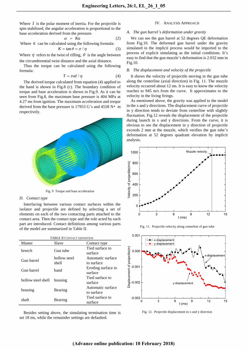
B. The displacement and velocity of the projectile
It shows the velocity of projectile moving in the gun tube
along the centerline (axial direction) in Fig. 11. The muzzle
velocity occurred about 12 ms. It is easy to know the velocity
reaches to 945 m/s from the curve. It approximates to the
velocity in the living firings.
As mentioned above, the gravity was applied to the model
in the x and y directions. The displacement curve of projectile
in y direction tends to deviate from centerline with slightly
fluctuation. Fig.12 reveals the displacement of the projectile
during launch in x and y directions. From the curve, it is
obvious to see the displacement in y direction of projectile
exceeds 2 mm at the muzzle, which verifies the gun tube’s
deformation at 52 degrees quadrant elevation by implicit
analysis.
Fig. 11. Projectile velocity along centerline of gun tube
Fig. 12. Projectile displacement in x and y direction
Engineering Letters, 26:1, EL_26_1_05
(Advance online publication: 10 February 2018)
______________________________________________________________________________________

C. The bearing’s dynamic response
The bearings are regarded as the critical parts in the isolator;
they realize the relative rotation between the projectile and the
fixed canard. The bearing is sensitive to the shock loadings so
that it is easy to be out of shape and crack in the process of
launch. Therefore, we conduct an analysis for the dynamic
response of the three bearings in the isolator shown in Fig.13
through implicit-explicit sequential simulation in the
following sections.
There are two simplified ball bearings in isolator showed in
Fig.13. They are comprised of the inner ring, outer ring and
the rollers. It is obvious to see one ball bearing on the right
side is smaller than the other one. It is labeled No.1.The
bigger one on the left side is labeled No.2. Fig.14 shows the
configuration of the No.1 ball bearing. The dynamic response
of the two ball bearings and the thrust bearing under shock
loadings are discussed as follows.
Outer ring Inner ringRoller
Fig. 14. No.1 ball bearing
We can see the axial acceleration’s changing curve of the
three parts in No.1 bearing during lunch from Fig.15, 16 and
17. As can be seen in the figure, the variation tendency of
curves is similar to the change of base pressure. The axial
acceleration of the outer ring, inner ring and roller reach to the
maximum 20,800 G’s synchronously. The maximum appears
at about 4.3 ms. The fluctuate curves whose value is up to at
least 10,000 G’s at about 12 ms indicate the projectile
vibrations when the axial force is removed. Therefore, the
axial loading is mainly affected by such two factors as base
pressure in the internal barrel and pressure dissipation at the
muzzle exit.
Fig. 15. Acceleration of No.1 ball bearing’s outer ring
We also can see transverse acceleration’s changing curve
of the three parts in No.1 bearing in the process of projectile
moving from Fig.15, 16 and 17. The graph describes that
transverse load increases gradually when the projectile moves
near the muzzle exit under the effect of the gun tube’s
deformation. It is similar with the axial acceleration. The
fluctuation of curve at about 12 ms shows the transverse
load’s high frequency oscillation resulted from pressure
dissipation. The transverse acceleration’s numerical value of
roller, outer ring and inner ring in No.1 bearing occurring at
about 12 ms are 15,100 G’s, 8,400 G’s and 14,300 G’s,
respectively.
Fig. 16. Acceleration of No.1 ball bearing’s inner ring
Fig. 17. Acceleration of No.1 ball bearing’s roller
Outer ring Inner ringRoller
Fig. 18. No.2 ball bearing
Engineering Letters, 26:1, EL_26_1_05
(Advance online publication: 10 February 2018)
______________________________________________________________________________________

Fig. 19. Acceleration of No.2 ball bearing’s outer ring
Fig. 20. Acceleration of No.2 ball bearing’s inner ring
Fig. 21. Acceleration of No.2 ball bearing’s roller
Similarly, it shows the simplified configuration of the No.2
bearing in Fig.18. It is obvious to see the change of the axial
acceleration from the Fig.19, 20 and 21. It is similar with the
No.1 bearing. The axial acceleration’s maximum of roller,
outer ring and inner ring reach to about 20,700 G’s at about
4.4 ms. It also can be seen from Fig.19, 20 and 21 that the
change of transverse acceleration of the three parts in No.2
bearing with projectile travelling in the tube. In addition to the
curves’ fluctuating at muzzle exit, the curves of roller and
outer ring fluctuate sharply from ignition to 5 ms. The
vibration amplitude of them are 12,900 G’s and 13,900 G’s,
respectively. The accelerative spinning of projectile and
violent impacts with the barrel inside wall may contribute to
such high transverse shock.
As Fig.22 shows, the simplified thrust bearing is comprised
of needle roller, cage, shaft washer and seat washer. The
change of the thrust bearing’s axial acceleration showed in
Fig.23, 24 and 25 is identical with the trend of base pressure,
whose maximum reach to 20,700 G’s at about 4 ms. The
thrust bearing’s change of transverse acceleration is also
described in Fig.23, 24 and 25. The transverse acceleration of
needle roller reaches the top at 6.6 ms, not at the time that
projectile moves out of the muzzle exit. The thrust bearing is
tend to be more vulnerable than the ball bearings when it
meets the transverse shock loadings, such as the centrifugal
inertia force and gyroscopic couple produced by the
accelerative spinning of projectile and violent impacts with
the barrel inside wall. According to the boundary conditions,
the base pressure can influence projectile’s spin. Therefore,
the transverse shock is affected by the factors such as the gun
tube deformation, the spinning produced by the base pressure
and the pressure dissipation at muzzle exit.
Seat washer Axis washerNeedle rollerCage
Fig. 22 The thrust bearing
Fig. 23. Acceleration of thrust bearing’s shaft washer
Based on the acceleration, the axial and transverse’s
applied force can be calculated if the mass of bearing has been
given. Then, we will deduce a calculation method to obtain
the maximum contact stress resulted from the maximum
acceleration on the basis of Hertz theory.
Engineering Letters, 26:1, EL_26_1_05
(Advance online publication: 10 February 2018)
______________________________________________________________________________________

Fig. 24. Acceleration of thrust bearing’s seat washer
Fig. 25. Acceleration of thrust bearing’s needle roller
D. Stress analysis
The maximum contact stress and deformation of bearing
are affected by the parameters such as elasticity modulus,
poisson's ratio, curvature sum , curvature difference
F and load.
As mentioned in previous section, the bearings experienced
combined the axial load aF the transverse load
tF at any
moment during the launch process. For the ball bearing whose
contact angle under this condition, maxQ should be
calculated through the formula in the following:
max sin
FaQ
J Za
(5)
Where Ja is the thrust integral which is determined by the
dimension of the ball bearing and Z is the number of the
rolling elements. The thrust load Fa and the radial load tF
can be obtained through Newton’s Law if the bearing’s
acceleration and mass have been known.
In this paper, the bearings are made of steel. Therefore, for
the two ball bearings, the contact type is point contact, and the
shape of the deformed surface is an ellipsoid of revolution.
The maximum contact stress and deformation can be
calculated based on the following formulas: 1/3
* max0.0236Q
a a
(6)
1/3* max0.0236
Qb b
(7)
4 2/3 1/32.79 10 maxQ (8)
3 maxmax
2
Q
ab
(9)
Where is the relative approach of remote points in the
contacting bodies. a and b are the dimensionless
semi-major axis of contact ellipse, and the dimensionless
contact deformation are the function of curvature
difference F . a and b are the semi-major axis of the
projected contact ellipse which are showed in Fig.26 and 27.
Different with the ball bearing, the contact type of thrust
bearing is line contact, and the shape of the deformed surface
is a semi-cylindrical form. For this condition, the maximum
contact stress and deformation can be calculated based on the
following formulas:
2 maxmax
Q
lb
(10)
1/23 max3.35 10
Qb
l
(11)
Where b is the semi-width of the contact surface showed in
Fig. 28 and 29.
b
a
z
yx
max
Fig. 26. Ellipsoidal surface compressive stress distribution of point contact
of ball bearing
2a
2b
2b
2a
Q Q
Z
Y
Z
X
Fig. 27. Surface compressive stress distribution of point contact
Based on the analysis in Part C of Section IV, we can obtain
the maximum acceleration of the two ball bearings and the
thrust bearing in axial and transverse direction. However, it
can be apparently seen that the maximum axial and transverse
acceleration do not occur simultaneously. Thus, we calculate
the maximum contact stress of the three bearings’ components
in the condition of the maximum acceleration in the axial and
transverse direction, respectively. Table III, IV and V shows
Engineering Letters, 26:1, EL_26_1_05
(Advance online publication: 10 February 2018)
______________________________________________________________________________________

the calculated maximum contact stress of the three bearings’
components.
l
b
max
Fig. 28. Semi-cylindrical surface compressive stress distribution
of line contact of thrust bearing
2b
Q
Z
Y
l
Q
l2b
Z
X
Fig. 29 Surface compressive stress distribution of line contact
Furthermore, we also acquired the maximum contact stress
of the three bearings’ components through simulation to
compare the calculated results. It is obvious to see the contact
stress time history which is about three bearings’ components
from Fig.30, 31 and 32. The simulation values of those
components’ contact stress are extracted from those figures
and listed them in Table VI, VII and VIII.
It can be discovered from the data in Table III that stress of
No.1 bearing’s outer ring, inner ring and roller in the
condition of maximum axial acceleration is larger than the
stress when those are subjected to the maximum transverse
acceleration. On the contrary, for the No.2 ball bearing, the
stress under the condition of maximum transverse
acceleration is larger than that under the maximum axial
acceleration based on the data in Table IV. The results
indicate that the contact stress of bearing is decided by the
axial and transverse shock loadings together. For thrust
bearing, from data in Table V it can be apparently illustrated
that the axial shock loadings could be the main factor which
decides the maximum contact stress of the thrust bearing.
Although the thrust bearing is tend to be vulnerable to
transverse shock loadings.
Compared with the calculation results extracted from Table
III, IV and V and added in Table VI, VII and VIII, on the one
hand, it can be seen that the moment of simulation results is
relatively close to the calculation results. On the other hand,
the calculated values maximum contact stress are relatively
close to the simulation values. The calculation results and the
simulation results are approximative. This verifies the validity
and feasibility of the maximum contact stress’s calculative
method.
TABLE VI SIMULATION AND CALCULATION VALUES OF MAXIMUM CONTACT
STRESS OF THE NO.1 BALL BEARING’S COMPONENTS
No.1 ball bearing outer
ring
inner
ring roller
simulation
results
moment (ms) 4.66 5.05 5.2
Maximum
contact stress
(MPa)
109 150 188
calculation
results
moment (ms) 4.3 4.3 4.3
Maximum
contact stress
(MPa)
104 145 177
TABLE VII SIMULATION AND CALCULATION VALUES OF MAXIMUM
CONTACT STRESS OF THE NO.1 BALL BEARING’S COMPONENTS
No.2 ball bearing outer
ring
inner
ring roller
simulation
results
moment (ms) 3.07 3.26 2.8
Maximum
contact stress
(MPa)
409 511 693
calculation
results
moment (ms) 3.48 3.27 2.2
Maximum
contact stress
(MPa)
397 518 637
TABLE VIII SIMULATION AND CALCULATION VALUES OF MAXIMUM
CONTACT STRESS OF THE THRUST BEARING’S COMPONENTS
thrust bearing shaft
washer
seat
washer
needle
roller
simulation
results
moment (ms) 5.14 5.08 3.7
Maximum
contact tress
(MPa)
483 522 1,102
calculation
results
moment (ms) 4.36 4.56 3.9
Maximum
contact tress
(MPa)
476 513 1,043
Fig.30. Simulation contact stress of No.1 ball bearing during launch process
Engineering Letters, 26:1, EL_26_1_05
(Advance online publication: 10 February 2018)
______________________________________________________________________________________

Fig.31. Simulation contact stress of No.2 ball bearing during launch process
Fig.32. Simulation contact stress of thrust bearing during launch process
In addition, it is obvious to see that the bearings’
deformation are within the scope of elasticity by comparing
with the yield stress of bearing steel (quenched and tempered)
in Table I. Therefore, the data results indicate that the two ball
bearings and the thrust bearing can work well during flight
after launch.
V. CONCLUSION
Course Correcting Fuse within a projectile is subjected to
high shock loadings during launch. The researchers used the
traditional method to oversimplify the model to study
dynamic response of the components in ammunition under
severe shock loadings. Beyond that, they also neglected the
effect of gravity; gun tube’s deformation and muzzle’s
pressure dissipation. Therefore, this paper presents a research
method for shocks on the rotation isolator used in this fuse,
which can realize the relative rotation between projectile and
fuse. The researchers design a integrated model which
includes the isolator, the projectile and gun tube.
With the help of the implicit-explicit sequential finite
element dynamic analysis, we can obtain the displacement in
x and y direction and the muzzle velocity and verify the gun
tube’s deformation under gravity. Then the dynamic response
of bearings is described. It can be concluded that the base
pressure is the key factor to affect the axial maximum loads
applied on the fuse. The gun tube’s deformation under gravity,
base pressure and pressure dissipation which result in the
fluctuating transverse shock loadings cannot be neglected.
Besides, due to the projectile’s accelerative spin and violent
collision with the barrel’s inside wall, the transverse shock
loadings is tend to be influenced by centrifugal inertia force
and gyroscopic couple. The research results can be useful for
reducing chances for the fuse’s failure during launch..
According to the acceleration acquired by simulation, a
calculation method is proposed to work out the maximum
contact stress of the bearing’s components. The method is
combined with the bearing’s maximal contact stress in the
process of simulation. The results verify the calculation
method’s validity and applicability by comparing the
numerical value of the bearing’s maximal contact stress.
Besides, the results indicate that bearings can operate
normally during launch. This kind of structure design of
rotation isolator used in the fuse can be a reference for
engineers’ research about the loading equipment.
REFERENCES
[1] T. E. Simkins, G. A. Pflegl, and E. G. Stilson, “Dynamic strains in a
60MM gun tube: an experimental study,” Journal of Sound Vibration,
vol. 168, 1993, pp.549-557.
[2] M. S. L. Hollis, “Use of finite-element stress analysis in the design of a
tank-cannon- launched training projectile,” Report for the Department
of Army, Report no. ARL-MR-149, September 1994.
[3] D. A. Hopkins, Wilkerson SA. “Analysis of a balanced breech system
for the M1A1 main gun system using finite element techniques,”
Report for the Department of Army, Report no. ARL-TR-608,
November 1994.
[4] D. E. Carlucci, J. Cordes, J. Hahn, et al, “Electronics and the gun
environment,” Ferroelectrics, vol.342, 2006, pp.193–204.
[5] B. R. Sorenson, “Design and analysis of Kinetic energy projectile using
Finite-Element Optimization,” Report for the Department of Army.
Report no. BRL-TR-3289, November 1991.
[6] G. M. Heaslip, J. M. Punch, “Analysis of experimental shock and
impact response data of a printed wire board,” 2003 ASME
International Mechanical Engineering Congress, Washington D. C.,
2003.
[7] S. S. Kessler, S.M. Spearing, “Design, analysis and Tesing of a high-g
composite fuselage structure,” Proceedings of the American society of
composite, Dayton, 2000.
[8] M. R. Chowdhury, A. Frydman, J. S. Corde, et al. “3-D Finite-element
gun launch simulation of a surrogate Excalibur 155 mm guided
artillery projectile-modeling capabilities and its implications,” 22nd
International Symposium on Ballistics, Vancouver BC, 2005.
[9] E. Petersen, “AGS barrel motion during firing: experimental and
modeling results,” Proceedings of the 2005 SEM annual conference
and exposition on experimental and applied mechanics, Bethel, 2005.
[10] V. Chakka, M. B. Trabia, B. J. O’Toole, et al, “Modeling and reduction
of shocks one electronic components within a projectile,”
International Journal of Impact Engineering, vol. 35, 2008,
pp.1326-1338.
[11] J. T. Tzeng, W. Sun, “Dynamic response of cantilevered rail guns
attributed to projectile/gun interaction-theory,” IEEE Transaction on
Magnetics, vol. 43, 2007, pp.207-213.
[12] K. D. Laughlin, “Characterization of the parameters that affect
projectile balloting using finite element analysis,” Ph.D. Thesis,
University of Oklahoma, 2008.
[13] D. S. Somasundaram, “Experimental investigation of shock mitigation
of electronic boards within projectiles,” M. S. Thesis, University of
Nevada, 2008.
[14] L. E. Reinhardt, J. A. Cordes, A. S. Haynes, et al. “Assessment of Need
for Solder in Modeling Potted Electronics During Gun-Shot,”
International Journal of Applied Mechanics, vol. 80, 2013,
pp.031502.
[15] X. W. Yin, P. Verberne and S. A. Meguid, “Multiphysics modeling of
the coupled behavior of precision-guided projectiles subjected to
intense shock loadings,” International Journal of Mechanics and
Materials in Design, vol. 10, 2014, pp.439-450.
[16] S. J. ValderRade, D. A. Inman, and J. Daniel, “Using passive
techniques for vibration damping in mechanical systems,” Journal of
the Brazilian Society of Mechanical Sciences and Engineering, vol. 22,
2000, pp.411-421.
Engineering Letters, 26:1, EL_26_1_05
(Advance online publication: 10 February 2018)
______________________________________________________________________________________

[17] S. Sueki, S. G. Ladkany and B. J. O’Toole, “Experimental and
computational study of acceleration response in layered cylindrical
structure considering impedance mismatch effect,” Shock and
Vibration, vol. 18, 2011, pp.807-826.
[18] D. Carlucci, J. Cordes, S. Morris, et al. “Muzzle Exit (Set Forward)
Effects on Projectile Dynamics,” Report for the Department of Army,
Report no. ARAET-TR-06003, 2006.
[19] M. Berman, D. Hopkins, D. Powers, et al. “Numerical and
Experimental Modeling of the Transition from Transient to
Quasi-static Loading of Printed Wiring Assemblies,” 2003 SEM
Annual Conference and Exposition on Experimental and Applied
Mechanics, Charlotte, 2003.
[20] J. A. Cordes, J. Vega, D. E. Carlucci, et al. “Structural loading statistics
of live gun firings for the army’s Excalibur projectile,” Report for the
Department of Army, Report no. ARAET-TR- 05005, 2005.
[21] S. Cui, X. Li, S. Wu, et al. “Anti-shock analysis of the electromagnetic
launched projectile powered by the pulsed alternator,” 19th IEEE
International Pulsed Power Conference, San Francisco, 2013.
[22] M. M. Chen, “Projectile balloting attributable to gun tube curvature,”
Shock and Vibration, vol.17, 2010, pp. 39-53.
[23] K. Kuncham, “Shock effects on electronic components within a
projectile,” M.S. Thesis, University of Nevada, 2006.
[24] J. A. Cordes, J. Lee, T. L. Myers, “Statistical Comparisons Between
Qualification Tests for Gun-Fired Projectiles,” Journal of Applied
Mechanics, vol.77, 2010, pp. 051602
Projectile
Rotation Isolator
Course Correction Fuze
Fixed Canard
Fig. 2. Rotation isolator in the Course Correcting Fuse
shaft
housing
deep groove ball
bearing
axial needle roller
thrust bearing
buffer
payload
Fig. 3. Sectional view of the rotation isolator
Fig. 4. Sectional view of gun tube and projectile with isolator
Engineering Letters, 26:1, EL_26_1_05
(Advance online publication: 10 February 2018)
______________________________________________________________________________________

2.032mm
Fig. 10. Gun barrel’s deformation due to gravity at 52 degrees quadrant elevation
Ball bearing Thrust bearing
Bearing No.2 Bearing No.1
Shaft washer Seat washer
Needle roller
Fig. 13. Bearings in the isolator
TABLE I MATERIAL PROPERTIES AND CHARACTERISTICS OF MODEL
Part name Material Young’s modulus (GPa) Poisson’s ratio Yield stress (MPa)
gun tube
breech Alloy steel 380 0.32 1104
band Red copper 125 0.34 206
hollow steel shell 4030 steel 210 0.29 510
charge TNT 4.13 0.40 ———
housing
shaft Aluminum alloy 71 0.33 280
bearing Bearing steel (quenched
and tempered ) 219 0.30 1668
TABLE III CALCULATED VALUE OF MAXIMUM CONTACT STRESS OF NO.1 BALL BEARING
No.1 ball
bearing outer ring inner ring roller
state axial
maximum
transverse
maximum
axial
maximum
transverse
maximum
axial
maximum
transverse
maximum
moment (ms) 4.3 1.7 4.3 12.04 4.3 12.04
axial
acceleration
(G’s)
20800 8690 20800 9680 20,800 5,950
transverse
acceleration
(G’s)
680 17800 848 14300 567 15,100
contact stress
(MPa)
104
(maximum) 61
145
(maximum) 15
177
(maximum) 105
Engineering Letters, 26:1, EL_26_1_05
(Advance online publication: 10 February 2018)
______________________________________________________________________________________

TABLE IV CALCULATED VALUE OF MAXIMUM CONTACT STRESS OF NO.2 BALL BEARING
No.2 ball
bearing outer ring inner ring roller
state axial
maximum
transverse
maximum
axial
maximum
transverse
maximum
axial
maximum
transverse
maximum
moment (ms) 4.4 3.48 4.4 3.27 4.4 2.2
axial
acceleration
(G’s)
20712 19109 20720 18523 20,710 10,692
transverse
acceleration
(G’s)
154 13900 215 4120 1,250 12,900
contact stress
(MPa) 191
397
(maximum) 409
518
(maximum) 167
637
(maximum)
TABLE V CALCULATED VALUE OF MAXIMUM CONTACT STRESS OF THRUST BEARING
thrust bearing shaft washer seat washer needle roller
state axial
maximum
transverse
maximum
axial
maximum
transverse
maximum
axial
maximum
transverse
maximum
moment (ms) 4.36 12.1 4,56 12.4 3.9 6.6
axial
acceleration
(G’s)
20700 4880 20700 1380 20,700 15,400
transverse
acceleration
(G’s)
1690 14900 1390 7220 6010 26,200
contact stress
(MPa)
476
(maximum) 19
513
(maximum) 9
1043
(maximum) 30
Engineering Letters, 26:1, EL_26_1_05
(Advance online publication: 10 February 2018)
______________________________________________________________________________________