a real-time implementation of an advanced on, and accommo
TRANSCRIPT
NASA Technical Memorandum 83553
NASA-TM-8355319840005072
I__T-AA PAA_._#_Yq-OS-6el ......
A Real-Time Implementation of an AdvancedSensor Failure Detection, Isolation, andAccommodation Algorithm
John C. DeLaat and Walter C. MerrillLewis Research CenterCleveland, Ohio
Prepared [k)r theTwenly-second Aerospace Scicnces Meetingsponsored by the American Institute of Aeronautics and AstronauticsReno, Nc\ada, January 9-12, 1984
N/ A

A REAL-TIME IMPLEMENTATIONOF AN ADVANCEDSENSORFAILUREDETECTION,ISOLATION, AND ACCOMODATIONALGORITHM
John C. DeLaat and Walter C. Merrill
National Aeronautics and Space AdministrationLewis Research Center
Cleveland, Ohio 44135
Abstract show that it is a practical alternative to hardwaresensor redundancy. For this effort, the ADIA
In recent years, advanced control algorithms algorithm has been implemented on a real-time,for turbofan engines have been implemented using microprocessor-based controls computer. 9 Thisdigital electronic control mechanisms. However, implementation was achieved using parallel pro-digital electronic controls need some component cessing and a high level programming language.redundancy in order to attain sufficient reliabil- This paper describes the ADIA implementation. Theity. A sensor failure detection, isolation, and algorithm is described and the hardware and soft-accommodation algorithm has been developed for ware considerations necessary to achieve the real-NASALewis Research Center which incorporates ana- time implementation are discussed along with somelytic sensor redundancy through software. This of the practical experience gained during thealgorithm has been implemented in a high level process.language on a microprocessor based controls com-puter. Parallel processing and state-of-the-art ADIA Algorithm Description16-bit microprocessors are used along with effi-cient programming practices to achieve real-time The ADIA algorithm detects, isolates, andoperation, accommodates sensor failures in turbofan engine
control systems. The ADIA algorithm was developedIntroduction for NASALewis under contracts NAS3-22481 and
NAS3-23282 by Pratt and Whitney Aircraft with theirIn recent years, advanced aircraft turbine subcontractor Systems Control Technology. The
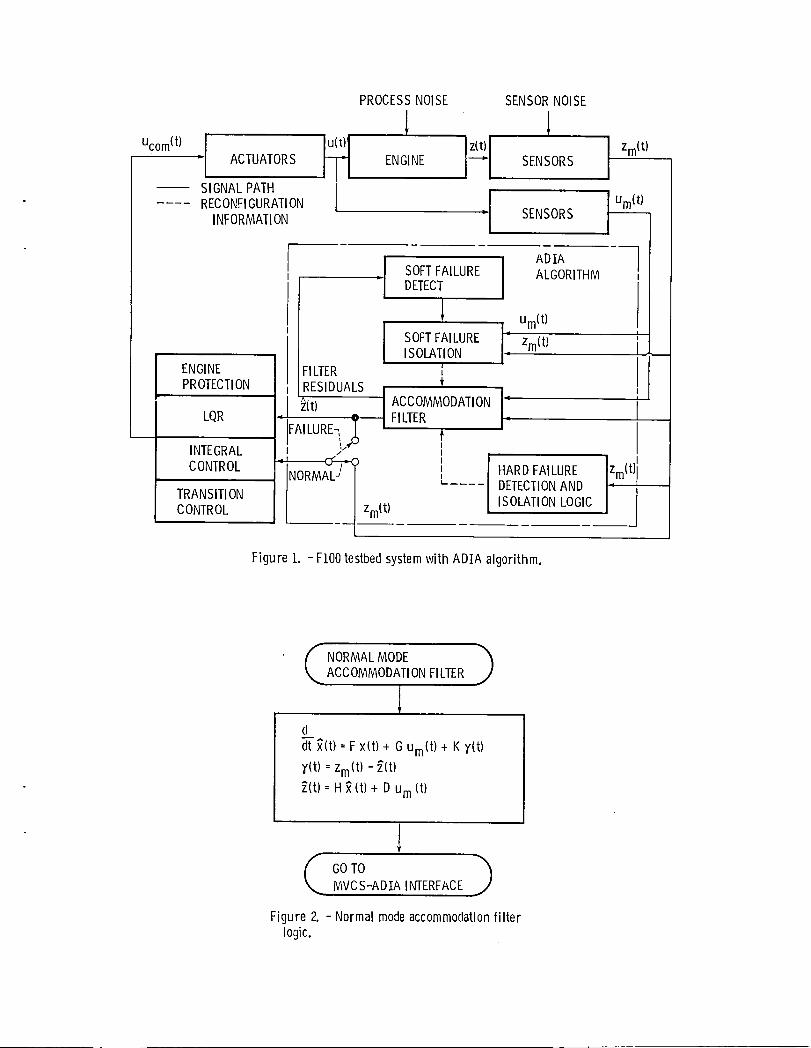
engine controls have been implemented using digital algorithm incorporates advanced filtering and de-electronic control mechanisms rather than the tection logic and is general enough to be appliedhydromechanical mechanisms of the past.l,2,3, 4 to different engine or other types of control sys~This allows the application of modern (optimal) tems. A specific version of the ADIA algorithmcontrol theory to the design of control algorithms was designed for use with the FIO0 engine and thewhich can take into account the loop interactions FIO0 Multivariable Control Synthesis (MVCS) programinherent in today's sophistocated turbofan engines, control.l,2, 3 This combination of engine, con-IIowever, studies have shown that current digital trol, and ADIA algorithm comprises the FIO0 Multi-electronic controls for turbine engines cannot variable Control testbed system and is shown inattain sufficient reliability without some level Fig. i.of control component redundancy.5, 6 There arethree major areas in which redundancy can be in- Algorithm Operationcorporated to improve the reliability of a digitalelectronic control system. They are the sensors, The ADIA algorithm consists of four elements:the actuators, and the controls computer itself. (i) hard failure detection and isolation logic,This effort addresses redundancy in the sensor set. (2) soft failure detection logic, (3) soft failure
isolation logic, and (4) an accommodation filter.Two methods are available for incorporating These are shown as part of the testbed system in
sensor redundancy. The first method, hardware Fig. I. The algorithm detects two classes of sen-redundancy, involves adding multiple identical sor failures, hard and soft. Hard failures aresensors to the control system. A technique such out-of-range or large bias errors that occur in-as voting can then be used to detect and isolate stantaneously in the sensed values. Soft failuressensor failures so that a faulty sensor can be are small bias errors or drift erors that accumu-eliminated from the system. Redundant multiple late relatively slowly with time.sensors, however, do have some drawbacks when in-corporated into a control system. Adding redundant The algorithm inputs are the measured enginesensors to the controls hardware will increase the inputs, Um(t), and the measured engine outputs,weight, cost, and complexity of the control system. Zm(t). These variables are defined in Table I.The second method of incorporating sensor redun- The algorithm outputs are optimal estimates, _(t),dancy is software or analytic redundancy. This of the engine outputs, z(t).method requires the controls computer, throughsoftware, to determine when a sensor failure has The algorithm has two modes of operation,occurred without redundant hardware sensors in the normal and failure. During normal mode operation,control system. The controls computer can then i.e., when no sensor failure is present, the normalprovide an estimate of the correct value of the mode accommodation filter uses all the measuredfailed sensor's output to the control algorithm, information to determine _(t). In failure mode
operation, one of the five sensors has failed.An advanced sensor failure Detection, Isola- Simultaneous multiple sensor failures are rare
tion, and Accommodation (ADIA) algorithm has been events and are not considered. A threefold processdeveloped for NASALewis Research Center under takes place once the failure has occurred. Firstcontract.7, 8 This algorithm has been evaluated the failure is detected. Once a failure is knownin nonreal-time using a digital simulation running to have occurred, the specific faulty sensor muston a mainframe computer. It is desirable to eval- be isolated. Finally, when isolation has occurred,uate the algorithm in a real-time environment to the failure is accommodated by reconfiguring the

normal mode accommodation filter which generates In the normal, no failure mode the output of thethe estimates, _(t). This threefold procedure accommodation filter, _(t) is fed to the LQRpor-takes place for both hard and soft failures, tion of the control while sensor outputs are fed
directly to the integral portion of the control.The normal mode accommodation filter logic, When a failure of sensor i is accommodated, the
shown in Fig. 2,^generates the estimates of the output of the reconfigured accommodation filter,engine outputs, z(t). In the Kalman filter equa- _(t), is fed to the LQR. Now, however, the ithtions, the matrices F, G, H, and D are typical element of _(t) replaces the ith sensor output,state space system matrices where x(t) is the which is faulty, in the integral control.4xi vector of estimates of the engine's state °variables and and y(t) is the 5xl vector of Using _(t) in the LQR in both modes mini-residuals. The matrix K is the Kalman gain mizes the transient impact of sensor failures onmatrix. All the system matrices as well as the the engine. However, the accommodation filterKalman gain matrix are scheduled as a function of will inevitably bias the estimates of the engineoperating point to model variations in engine dy- outputs, _(t), due to modelling error. So, in thenamics. Almost all of the matrices' elements are integral control during no failure mode operation,nonzero, thus, almost all the matrix elements must the measured values of engine outputs, Zm(t )be multiplied through the filter equations, are used so that the engine outputs rather that
the biased estimates of the engine outputs will beThe hard failure detection and isolation controlled to the desired setpoint. In the failure
logic, shown in Fig. 3, performs a straightforward mode, only the measurement corresponding to thethreshold check on each sensor residual, _i- failed sensor is replaced by an estimate to mini-Threshold values are determined from sensor and mize the effect of the biased terms. Transientprocess noise values as well as sensor range con- effects upon engine operation due to this signalsiderations. If a residual value is greater that switching are effectively removed by the filteringthe threshold, _H, hard failure detection and action of the integrators. A complete, detailedisolation follow immediately, description of the ADIA algorithm can be found in
Refs. 7 and 8.If a hard failure has not occurred, then a
soft failure check is performed. The soft failure Implementation Descriptiondetection logic, shown in Fig. 4, first calculatesan average weighted sum of squared residuals A real-time Intel 8086 microprocessor based(WSSR). A soft failure is detected when the control system has been designed and fabricated atweighted sum is greater than a prespecified soft NASALewis for controls research, g The controlsfailure detection threshold, _s. The number, N, microcomputer in this system uses an iSBC 86/30of past residuals summed to obtain the average, singe board computer as its central processingthe weighting factor, W, and the detection thresh- unit (CPU) and runs under a commercially availableold, _s, are design parameters that are chosen disk-based operating system. In addition to theto provide an acceptable tradeoff between false CPU board, the controls microcomputer contains twoalarms and missed detections, floppy disk drives and their associated controller,
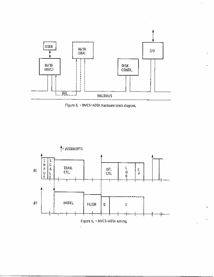
analog input/output boards, and digital input/Once a soft failure has been detected, the output boards. A block diagram of the system is
soft failure isolation logic, shown in Fig. 5, is shown in solid lines in Fig. 8. This system, wasused to isolate the failed sensor. Six different used in a previous effort to evaluate an implemen-isolation filters generate six different sets of tation of the FIO0 MVCScontrol algorithm in realresiduals, one for each possible failed sensor, time. I0 The controls computer with a 5 MHzand one based on no failed sensors. A log likeli- version of the 8086 was able to execute a fixedhood ratio, Hi is generated for each set of point assembly language implementation of the MVCSresiduals. A test is then performed which deter- algorithm in 19 msec. This implementation occupiedmines the most probable set of residuals by finding 13 kilobytes of microprocessor memory.the maximum Hi . When this maximum Hi isabove an isolation threshold, _I, the faulty During the nonreal-time evalutation of thesensor Is isolated. ADIA algorithm, it was estimated that the ADIA
would take at least as long to execute as the MVCSOnce a hard or soft failure is detected and algorithm. Thus it was estimated that the combined
isolated, the accommodation filter is reconfigured MVCS-ADIAwould take over 40 msec to execute.by an appropriate change of its Kalman gain matrix Previous evalutation of the MVDSalgorithm sug-K to remove the failed sensor from consideration gested that this execution time was too long toas shown in Fig. 6. For a soft failure of sensor achieve an update interval commensurate with thei, the accomodation filter is also reinitialized system dynamics. So it was decided to use parallelto the current value of zi(t) and xi(t ) processing to add computational power to the systemfrom the appropriate isolation filter. Reinitial- and thus speed up the execution time of the com-ization is necessary since a significant amount of bined MVCS-ADIAto acceptable levels. To achievetime will have elapsed between failure and parallel processing, a second 86/30 CPU board,isolation, shown in dashed lines in Fig. 8, was added to the
controls microcomputer. Since the ADIA and theAlgorithm Interface MVCSalgorithms have portions that can run in
parallel, the second CPU board is used to run theThe ADIA algorithm interface to the FIO0 MVCS ADIA algorithm while the first CPU board runs the
control is shown in Fig. I and in detail in Fig. MVCSalgorithm as it did in the previous effort.7. The MVCScontrol includes four major logic The bus structure designed into the controls micro-sections: (i) transition control, (2) integral computer for the MVCSevaluation allowed room forcontrol, (3) proportional control (Linear Quadratic expansion so that adding another CPUboard to theRegulator or LQR), and (4) engine protection logic, system was fairly straightforward. The interrupt
structure on this bus is used for communication than the software equivalent of the same instruc-and synchronization between the two CPUboards, tions would execute on the 8086 alone. Higher
maximumclock rate microprocessor chips are anetherThe resulting relative system timing, in- example of advanced microprocessor hardware. These
cluding the synchronization interrupts and the allow each instruction to execute proportionatelyparallel portions of the MVCS-ADIAalgorithm is faster.shown in Fig. 9. The blocks represent the varioussections of the two algorithms and the time it The ADIA algorithm was delivered to NASALewistakes to execute each section. Upon receiving the in FORTRAN. Since a good FORTRANcompiler isupdate interval interrupt, CPU board I gets the available for the 8086-8087 processors, FORTRANalgorithm inputs from the sensors through analog- was chosen as the high level language in which toto-digital converters. It then scales these inputs implement the ADIA algorithm. FORTRAN,however,to fixed point integers for the MVCSand to float- has the disadvantage that it cannot easily inter-ing point numbers for the ADIA. Board I then sends face to input/output hardware such as that contain-an interrupt to board 2 to tell it the inputs are ed in the controls microcomputer. For instance,available and to start processing. Board i then there is no instruction in FORTRANthat will outputcalculates the transition control. In parallel, directly to a digital-to-analog converter.board 2 does the engine model and accommodationfilter calculation. When board 2 has finished Therefore, a software implementation was ar-these calculations, it sends an interrupt to board rived at which takes advantage of the best features1 telling it that the estimates of the sensors are of both assembly language and FORTRAN. Assemblyavailable. Board 2 then performs the hard and language is used for the executive which calls thesoft failure detect logic and starts the soft algorithm subroutines, for all hardware input/failure isolation logic if necessary. Any failures output routines, and for the interrupt handlersisolated will be accommodated and flagged to board which allow communication between the two CPUi during the next update interval. While board 2 boards. In addition, since the MVCSalgorithm hadperforms the detect and isolate logic, board i been implemented and evaluated in assembly lan-finishes the MVCScalculation by computing the guage, the assembly language software is used forintegral control, the LQR, and the engine protect this effort. The ADIA algorithm is left in FORTRANlogic. The algorithm outputs are then passed to and therefore benefits from the advantages of athe engine actuators through digital-to-analog high level language implementation.converters. The next update interrupt will thentrigger the process again starting with the input Practical Experience Gainedand scaling of tile sensors.
A number of practical experiences were gainedUntil this effort, digital control algorithms during the process of building up the MVCS-ADIA
at NASALewis had been programmed exclusively in hardware and software. Many of these experiencesassembly language. It was generally believed that were driven by the fact that the ADIA algorithm asassembly code generated by hand would run faster received took over 600 msec to execute on the con-than code generated by a high level language com- trols microcomputer rather than the desired 20-30piler and was therefore necessary to achieve real- msec. More than an order of magnitude reductiontime execution of the control algorithms. As in execution time was necessary before real-timementioned earlier, the MVCSalgorithm was imple- evaluation could start. Most of the reduction wasmented using fixed point assembly language. Assem- achieved in two ways. First, the FORTRANcode forbly language also has the advantage that programs the ADIA algoritm was scrutinized to identify thosewritten in it can interface directly to input/ parts of the algorithm which could be made to runoutput hardware such as digital-to-analog con- faster through the use of efficient FORTRANpro-verters. However, assembly language has the dis- gramming. In line code was generated to take theadvantage that it is not an application oriented place of most of the DO loops and subroutine andlanguage. It is therefore very time consuming to function calls. The FORTRANcompiler was used toprogram a sophisticated application in assembly generate assembly language listings to aid inlanguage, identifying those constructs which generate in-
efficient code. Eliminating indexed addressing,To overcome this disadvantage, a decision was such as indexed array element references, and com-
made up front to implement the ADIA algorithm in a bining statements often helps the compiler optimizehigh level language. In addition to being easier the code it generates. The second method used toto program, a high level language implementation reduce execution times was to substitute assemblyalso has the advantage of being simpler to debug, language routines for the FORTRANroutines whichmaintain, and make changes to due to its increased could not be reduced sufficiently. Only one sec-readability over assembly language. Two factors tion of the ADIA algorithm had to be converted toallow the use of a high level language for real- assembly language. This section involves manytime control applications. First, manufacturers function look-ups and runs much faster in assemblyof high level language compilers for micropro- language.cessors are aware that fast execution is very im-portant to a vast number of end users of their As of the writing of this paper, the ADIAproducts. Thus current compilers have been de- algorithm is very close to being able to executesigned to generate efficient, optimized code. in the desired time. Higher speed versions of theSecond, advances in microprocessor hardware speed 8086-8087 microprocessors are on order which willallow the code generated by these compilers to be allow a direct increase in the speed of code exe-executed much faster than on previously attainable cution and will thereby eliminate any furtherhardware. One example of this advanced hardware worries about execution time. The version of theis the floating point coprocessor, such as an Intel algorithm incorporating all the changes made to8087. Running with an 8086 it can execute floating reduce execution time occupies about 40 kilobytespoint instructions in hardware many times faster of microprocessor memory.
Conclusions 5. McG1one, M. E., Davies, W. J., Miller, R. J.,Smith, T. B., LaLa, J. H., and Peck, W. C., "FuII-
A real time implementation of the FI00 MVCS- Authority Fault-Tolerant Electronic Engine ControlADIA algorithm has been achieved and is ready for Systems for Variable Cycle Engines," Pratt andevaluation. In order to take advantage of high Whitney Aircraft, AFWAL-TR-81-2121, Dec. 1981.level language programming, concentration of effort 6. Baker, L., Brainard, W. E., Curry, C. E., Dis-was necessary in two major areas. First, state-of- parte, C. P., Dolny, L. J., Fleming, R. E., andthe-art hardware including parallel processing, Warner, D. E., "Full-Authority Fault-Toleranthigh clock rate 16-bit microprocessors, and float- Electronic Engine Control Systems for Variableing point coprocessors must be used. Second, a Cycle Engines," Detroit Diesel Allison, AFWAL-thorough understanding of the FORTRANprogram, TR-82-2037, Apr. 1982.including what type of code the compiler will 7. Beattie, E. C., Laprad, R. F., McGlone, M. E.,generate, is necessary in order to generate Rock, S. M., and Akhter, M. M., "Sensor Failureexecution-time efficient code. Detection System - for the FI00 Turbofan Engine,"
Pratt and Whitney, East Hartford, Conn., PWA-In turn, several benefits are derived from 5736-17, Aug. 1981 (NASACR-165515).
implementing the algorithm in a high level fan- 8. Beattie, E. C., Laprad, R. F., Akhter, M. M.,guage. First, it is easier to understand what the and Rock, S. M., "Sensor Failure Detection for Jetprogram is doing. This makes validation of the Engines," Pratt and Whitney Aircraft, East Hart-program easier and allows engineers without a ford, Conn., PWA-5891-18, May 1983 (NASA CR-microprocessorlassembly language background to 168190).work with the program. Second, high level language 9. DeLaat, J. C., Soeder, J. F., "Design of aprograms are portable, that is, they can run on Microprocessor - Based Control, Interface, andmore than just the processor they were written Monitoring (CIM) Unit for Turbine Engine Controlsfor. Thus the programs can be evaluated and tested Research, NASATM-83433, 1983.on any number of computers. Therefore, it has 10. DeLaat, J. C., Soeder, J. F., "Evaluation of abecome a viable alternative and a beneficial one Microprocessor Implementation of the FIO0 Multi-to use high level language programming for complex, variable Control. Proposed NASATechnicalreal-time control algorithms. Memorandum.
References TABLE I. - ENGINEINPUTS AND OUTPUTS
i. Szuch, J. R., Soeder, J. F., Seldner, K., and Engine inputs:Cwynar, D. S., "FI00 Multivariable Control Synthe- Fuel flowsis Program: Evaluation of a Multivariable Control Nozzle areaUsing a Real-Time Engine Simulation," NASATP-I056, Compressor inlet guide vane angle1977. Rear compressor variable vane angle
2. Lehtinen, B., Dehoff, R. L., and Hackney, R. Bleed flowD., "Multivariable Control Altitude Demonstrationon the FIO0 Turbofan Engine," AIAA Paper 79-1204, Engine outputs:June, 1979. Fan speed
3. Soeder, J. F., "FIQO Multivariable Control Syn- Compressor speedthesis PRogram - Computer Implementation of the Burner pressureFIO0 Multivariable Control Algorithm," NASA Augmentor pressureTP-2Z31, 1983. Fan turbine inlet temperature
4. Arpasi, D. J., Zeller, J. R., and Batterton,P. G., "A General Purpose Digital System for On-line Control of Air Breathing Propulsion Systems,"NASATM X-2168, 1971.
PROCESSNOISE SENSORNOISE
Ucom"'.[ AO_O_O_S}_ _,0,,_I_ _,SO,S I_m"'RECONFIGURATION urn(t)INFORMATION " SENSORS
. SOFTFAILURE ALGORITHMDETECT
Um(t)
ISOLATION m
ENGINE FILTER ', IPROTECTION RESIDUALS t I
1 1 '_o_ _,. ACCO_O_A_,O._- '_A,W_-.._'_'_'_ '_-INTEGRAL J"_ I
' ICONTROL C¢-T'< , HARDFAILURE Zm(t)NORMAL"TRANSITION _-.... DETECTIONAND I--CONTROL Zm(t) ISOLATIONLOGIC I
Figure i. - FIO0testbedsystemwith ADIA algorithm.
NORMAL MODEACCOMMODATION FILTER
d
_- _(t) =Fxlt) + Gumlt) + K_'(t)
_,(t)=Zm(t) - _(t)
_(t) = H_ (t) + D um(t)
(ooToMVCS-ADTAINTERFACE
Figure2.-Normalmodeaccommodationfilterlogic.

- HARDFAILURE )DETECTANDISOLATE
1
_A OTO _ HARD FAILURE Y>_ >CCOMMODATIONy DETECTED
ANDISOLATED
[oo_o ")SOFTFAILUREDETECT j
Figure 3. - Hardfailure detectionand isolation logic.
SOFTFAILUREDETECT )
Ii_iYTwY
GOTONORMALMODEACCOMMODATIONFILTER
I SOFTFAILUREDETECTED
1GO TO )SOFTFAILUREISOLATION
Figure 4. - Softfailure detectionlogic.

SOFTFAILUREISOLATION_._
, Yi =zi-_i i =0..... 5
!WSSRi =1,iTw1,i
i--0 ..... 5
LOG 1LIKELIHOODRATIO
TEST Hi =WSSRo-WssR ii--i ..... 5
!FINDMAXHi ]
GOTOACCOMMODATION
I SOFTFAILURE IISOLATED
l• _ GOTOACCOMMODATION
Figure 5. - Soft failure isolation logic.

'_FAILUREACCOMMODATION
1RECONFIGUREK [
SOFT _,_YES
I +REINITIALIZE_i, _iII_° J
ACCOMMODATIONFILTER
Figure 6. - Failure accommodationlogic.

MVCS IADIAI
" 1LQR l ,, , _ (t)
,,II FROM] ACCOM.I FILTER
1 I FAILURE __ t
INT.CI-L. ACCOMMODATED_, Zm(t)- SENSOR#2--_
I I _ FROMENGINEI
FAILURE IACCOMMODATEDSENSOR#3 __I
/FAILUREACCOMMODATED,/SENSOR#4--/
!
FAILURE /ACCOMMODATED,'SENSOR#5 -----J
Figure 7. -MVCS-ADIA inmrface.
[_ 86130 I/0
I (DIA)Ii ....
_, "'T .... J
86/30 tI DISK(MVC) t CONTR.I
I
' INT. l MULTIBUS
Figure 8. - MVCS-ADIAhardwareblockdiagram.
f: INTERRUPTS
#i CTL. CTL. Qr R, ,, , t I , i
Jk
#2 MODEL FILTER I
l , I I I I IFigure9.-MVCS-ADIAliming.

,!
_f
_rb
i

1. Report No. 2. Government Accession No. 3. Recipienrs Catalog No.
NASATM-835534, Title and Subtitle 5. Report Date
A Real-Time Implementation of an Advanced Sensor Fail-ure Detection, Isolation, and Accommodation Algorithm 6.PerformingOrganizationCode
505-32-6B7. Author(s) 8. Performing Organization Report No.
E-I 928John C. DeLaat and Walter C. Merrill lO.WorkUnitNo.
9. Performing Organization Name and Address
National Aeronautics and Space Administration 11. Contract orGrant NO.Lewis Research Center
Cl evel and, 0hi o 44135 13.Type of Report and Period Covered
12. Sponsoring Agency Name and Address Technical MemorandumNational Aeronautics and Space AdministrationWashi ngton, D.C. 20546 14.SponsoringAgency Code
15. Supplementary Notes
Prepared for the Twenty-second Aerospace Sciences Meeting sponsored by theAmerican Institute of Aeronautics and Astronautics, Reno, Nevada, January 9-12,1984.
16. Abstract
In recent years, advanced control algorithms for turbofan engines have beenimplemented using digital electronic control mechanisms. However, digitalelectronic controls need some component redundancy in order to attain suffi-cient reliability. A sensor failure detection, isolation, and accommodationalgorithm has been developed for NASALewis Research Center which incorporatesanalytic sensor redundancy through software. This algorithm has been im-plemented in a high level language on a microprocessor based controlscomputer. Parallel processing and state-of-the-art 16-bit microprocessorsare used along with efficient programming practices to achieve real-timeoperation.
17. Key Words (Suggested by Author(s)) 18. Distribution Statement
Sensor failure; Detection; Isolation; Unclassified- unlimitedAccommodation; Microprocessor; Real-time STARCategory Ol
19. Security Classlf. (of this report) 20. Secudty Classlf. (of this page) 21. No. of pages 22. Price*
Unclassified Unclassi fied
*For sale by the NationalTechnical Information Service, Springfield,Virginia 22161

,ero,a,.and,PECALO'R..CA,,MA.]111Space Administration eOOK
Washington, D.C.20546
Official Business
Penalty for Private Use, $300Postage and Fees PaidNational Aeronautics andSpace AdministrationNASA-451
NASA DO NOT REMOVE SLIP FROM MATERIALIf Undeliverable {Secti,)n I ._
Delete your name from this slip when returning material P,,sta)M3nu.])I)O,NotF(,_l'ur,|to the library.
NAME DATE MS -
NASA Langley (Rev, Dec. 1991) RIAD N-75