a practical discussion of its uses and limitations in high ... · a practical discussion of its...
TRANSCRIPT
A Practical Discussion of Its Uses and Limitationsin High Frequency Transformers
Kyle D. JensenField Application Engineer
What is Litz Wire?
• Litzendraht – German word for “Stranded”
• While any stranded conductor can be referred to as Litz, we use the term to describe a conductor manufactured by twisting together individually insulated wires in specific patterns to produce a desired electrical effect.
What is Litz Wire?
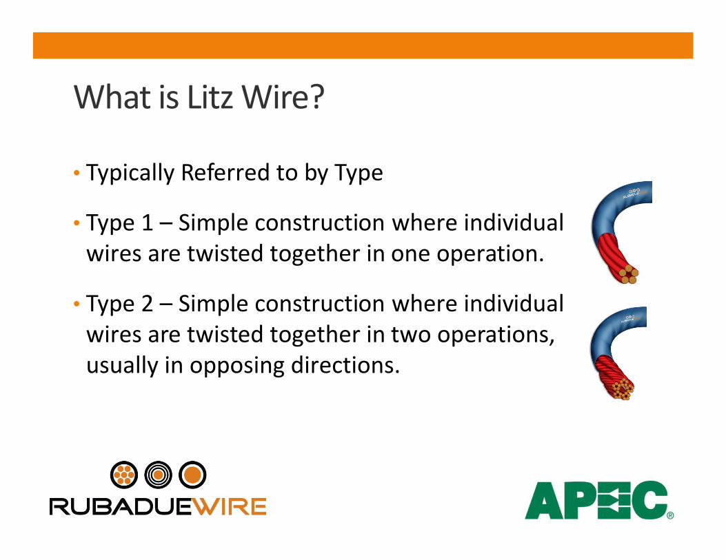
• Typically Referred to by Type
• Type 1 – Simple construction where individual wires are twisted together in one operation.
• Type 2 – Simple construction where individual wires are twisted together in two operations, usually in opposing directions.
What is Litz Wire?
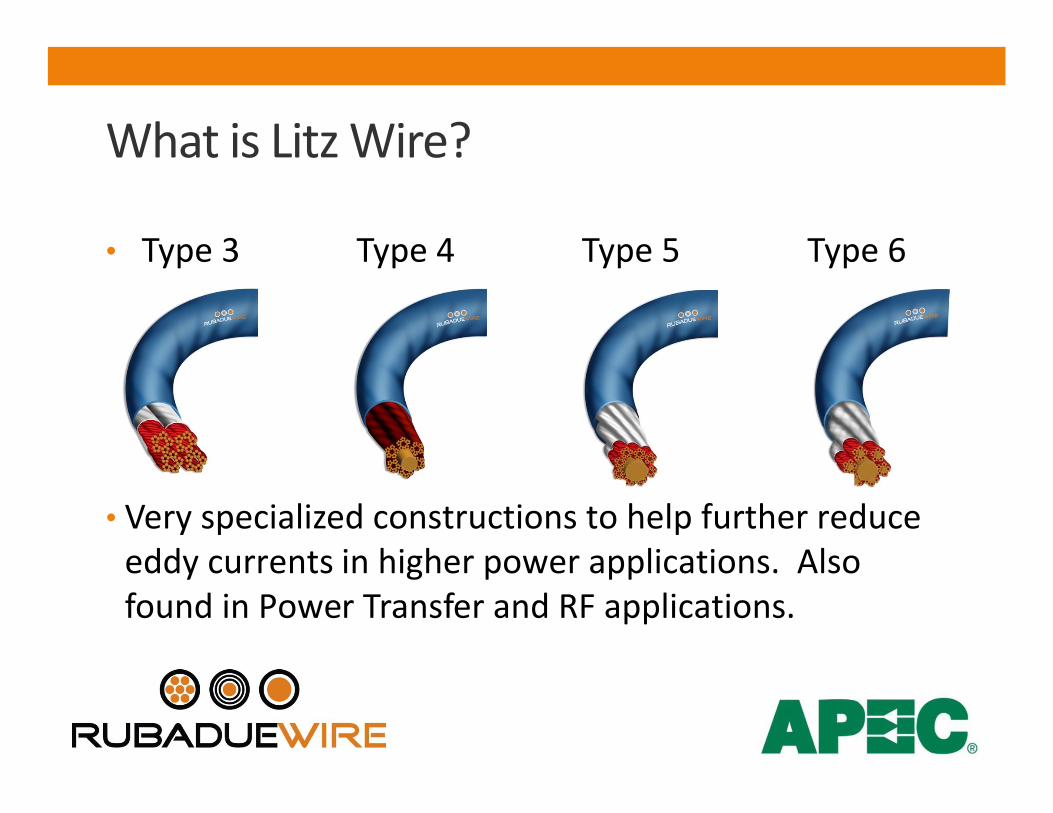
• Type 3 Type 4 Type 5 Type 6
• Very specialized constructions to help further reduce eddy currents in higher power applications. Also found in Power Transfer and RF applications.
What is Litz Wire?
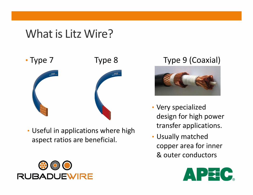
• Type 7 Type 8 Type 9 (Coaxial)
• Useful in applications where high aspect ratios are beneficial.
• Very specialized design for high power transfer applications.
• Usually matched copper area for inner & outer conductors

Why Use Litz Wire?
• When changing from a DC based design to one that employs AC, designers must take into consideration several key concerns that will affect the ultimate performance of the end product.
• Skin Effect• Proximity Effect• Increased Resistance in the winding
Why Use Litz Wire?
• Skin Effect – the tendency for current in an AC circuit to flow on the outer edges of the conductor resulting in increased resistance.
• Proximity Effect - the tendency for current to flow in other undesirable patterns (loops or concentrated distributions) due to the presence of magnetic fields generated by nearby conductors.
• In transformers and inductors, proximity-effect losses typically dominate over skin-effect losses.
Why Use Litz Wire?
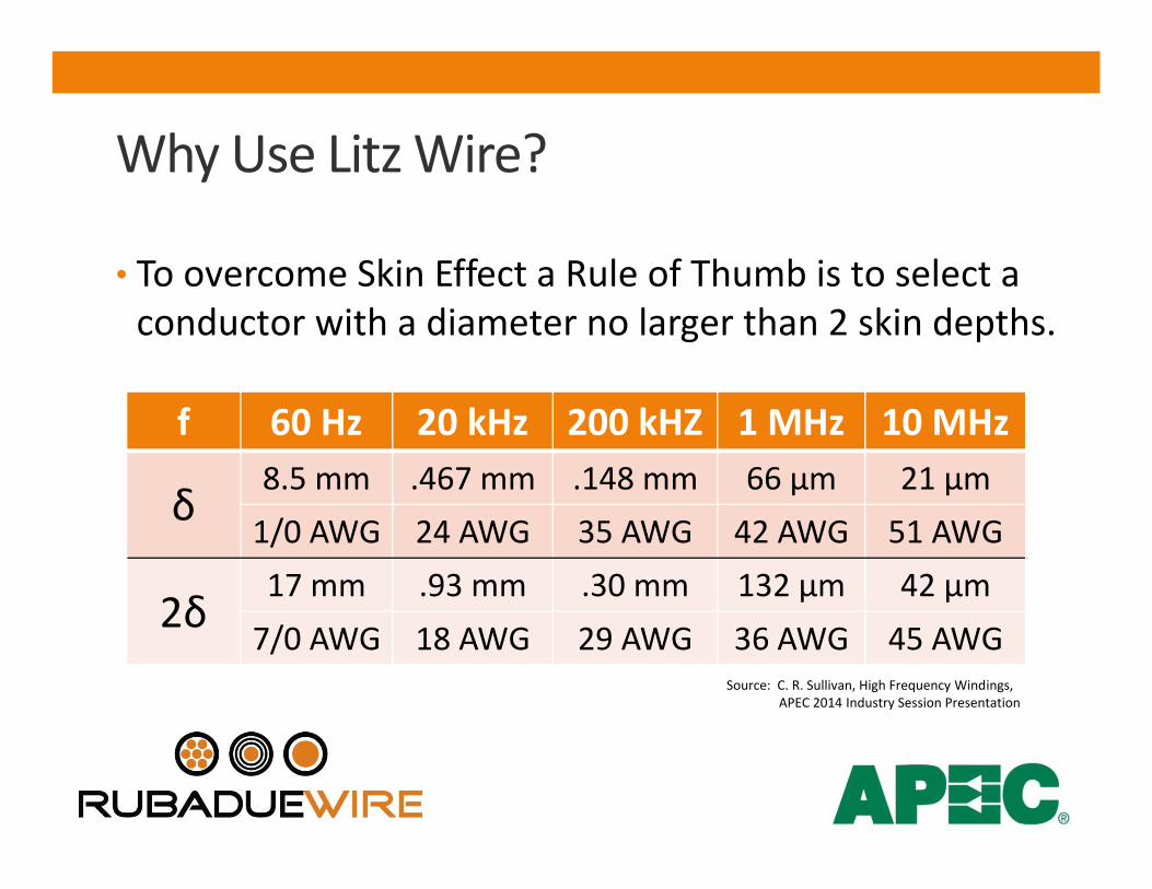
• To overcome Skin Effect a Rule of Thumb is to select a conductor with a diameter no larger than 2 skin depths.
f 60 Hz 20 kHz 200 kHZ 1 MHz 10 MHz
δ8.5 mm .467 mm .148 mm 66 µm 21 µm
1/0 AWG 24 AWG 35 AWG 42 AWG 51 AWG
2δ17 mm .93 mm .30 mm 132 µm 42 µm
7/0 AWG 18 AWG 29 AWG 36 AWG 45 AWGSource: C. R. Sullivan, High Frequency Windings,
APEC 2014 Industry Session Presentation
Why Use Litz Wire?
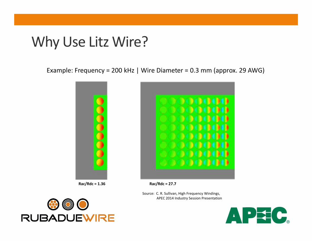
Source: C. R. Sullivan, High Frequency Windings, APEC 2014 Industry Session Presentation
Example: Frequency = 200 kHz | Wire Diameter = 0.3 mm (approx. 29 AWG)
Rac/Rdc = 1.36 Rac/Rdc = 27.7
Why Use Litz Wire?
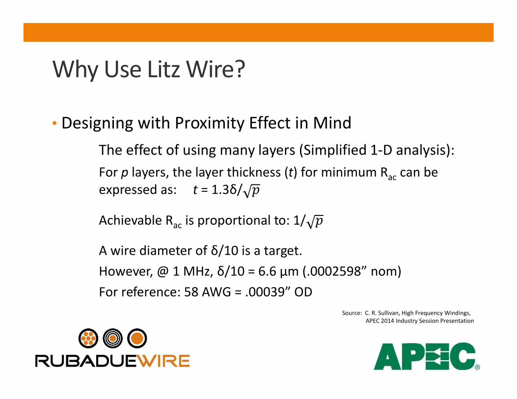
• Designing with Proximity Effect in MindThe effect of using many layers (Simplified 1-D analysis):For p layers, the layer thickness (t) for minimum Rac can be expressed as: t = 1.3δ/
Achievable Rac is proportional to: 1/
A wire diameter of δ/10 is a target. However, @ 1 MHz, δ/10 = 6.6 µm (.0002598” nom)For reference: 58 AWG = .00039” OD
Source: C. R. Sullivan, High Frequency Windings, APEC 2014 Industry Session Presentation
Why Use Litz Wire?
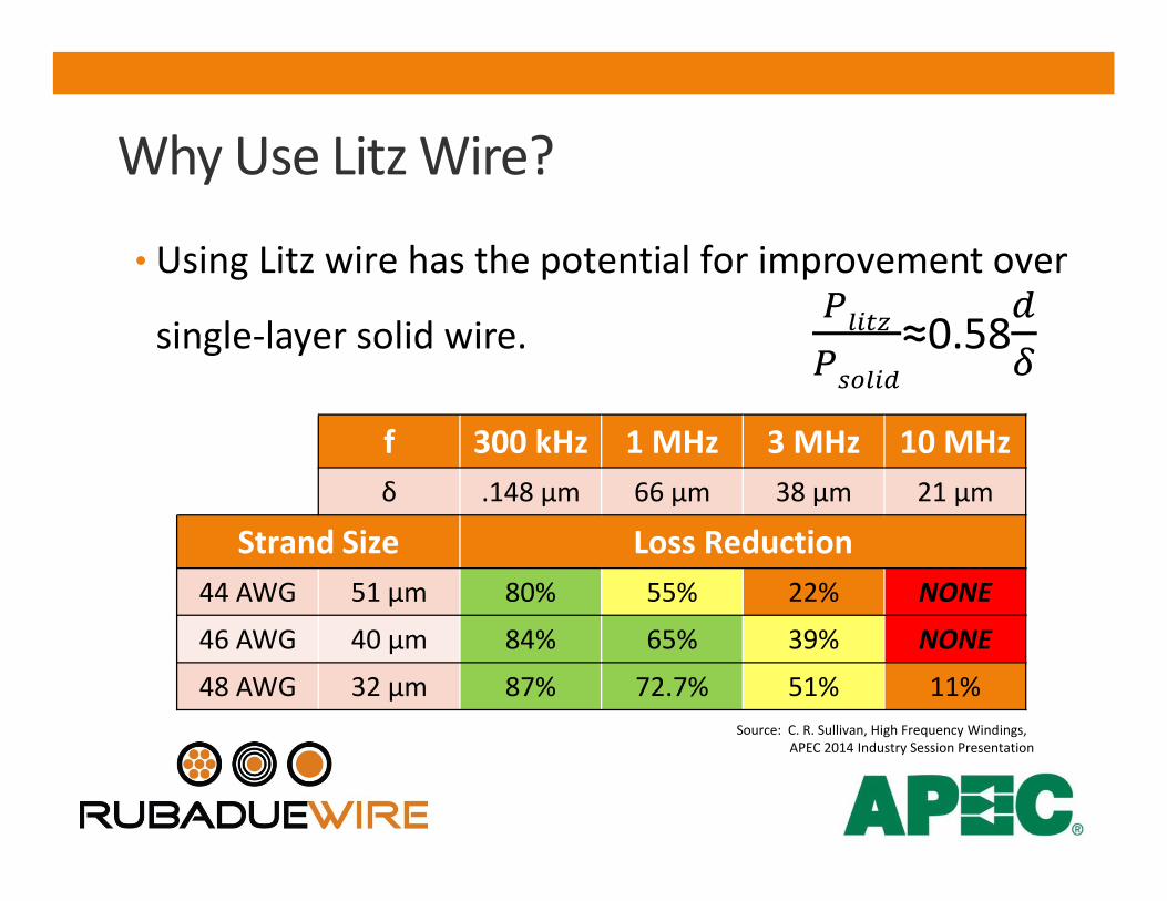
• Using Litz wire has the potential for improvement over
single-layer solid wire. ≈0.58
f 300 kHz 1 MHz 3 MHz 10 MHzδ .148 µm 66 µm 38 µm 21 µm
Strand Size Loss Reduction44 AWG 51 µm 80% 55% 22% NONE
46 AWG 40 µm 84% 65% 39% NONE
48 AWG 32 µm 87% 72.7% 51% 11%Source: C. R. Sullivan, High Frequency Windings,
APEC 2014 Industry Session Presentation
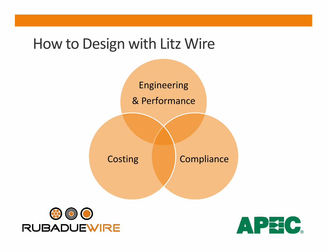
How to Design with Litz Wire
Engineering
& Performance
ComplianceCosting
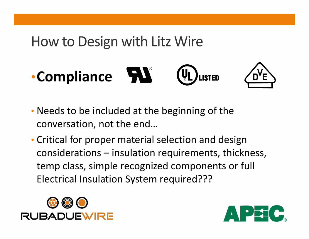
•Compliance
• Needs to be included at the beginning of the conversation, not the end…
• Critical for proper material selection and design considerations – insulation requirements, thickness, temp class, simple recognized components or full Electrical Insulation System required???
How to Design with Litz Wire

•Design Considerations• Operating Frequency or Effective Frequency for
nonsinusoidal currents.• Total Current• Voltage / Electrical Insulation Requirements• Acceptable Heat Rise• Litz packing factor / increased conductor diameter
How to Design with Litz Wire
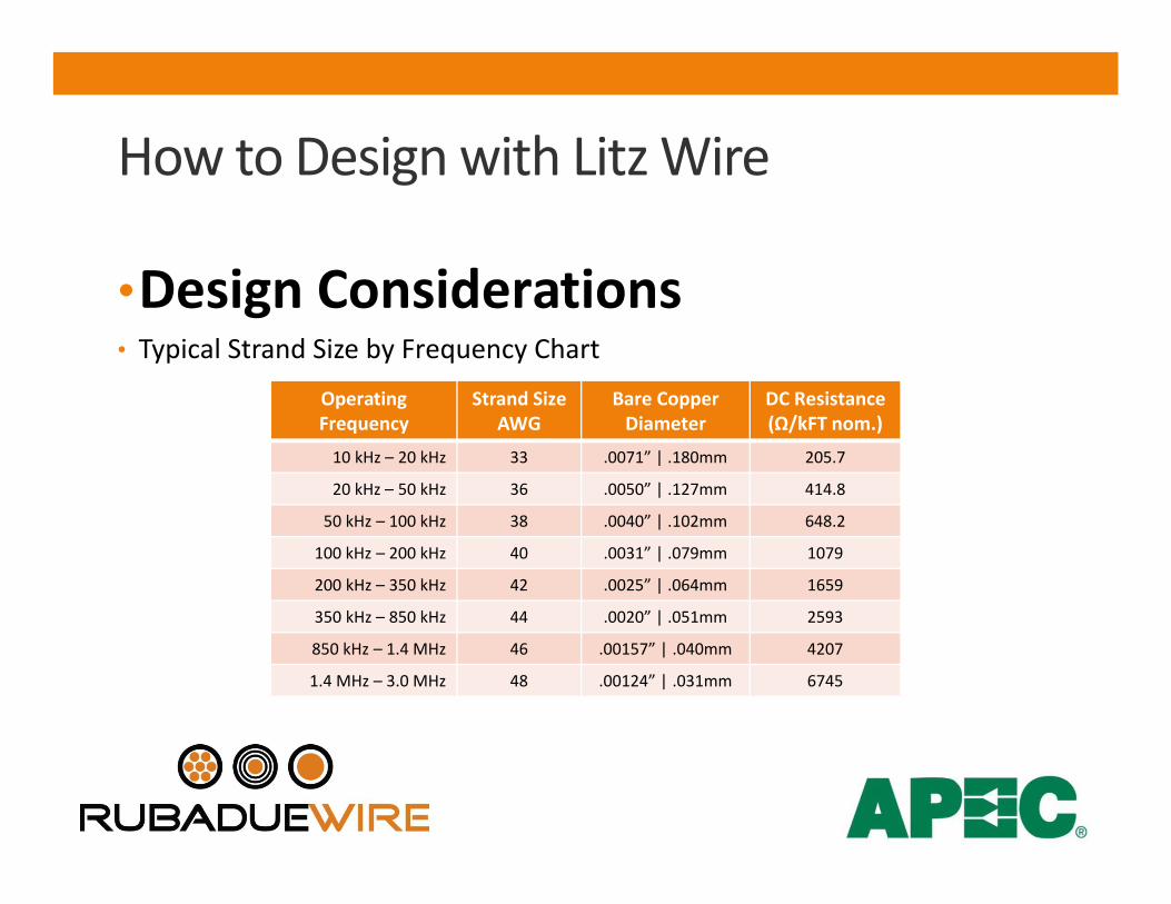
•Design Considerations• Typical Strand Size by Frequency Chart
How to Design with Litz Wire
OperatingFrequency
Strand Size AWG
Bare Copper Diameter
DC Resistance(Ω/kFT nom.)
10 kHz – 20 kHz 33 .0071” | .180mm 205.7
20 kHz – 50 kHz 36 .0050” | .127mm 414.8
50 kHz – 100 kHz 38 .0040” | .102mm 648.2
100 kHz – 200 kHz 40 .0031” | .079mm 1079
200 kHz – 350 kHz 42 .0025” | .064mm 1659
350 kHz – 850 kHz 44 .0020” | .051mm 2593
850 kHz – 1.4 MHz 46 .00157” | .040mm 4207
1.4 MHz – 3.0 MHz 48 .00124” | .031mm 6745

•Design Considerations• Strand Size by Frequency Charts, while helpful for
coming up with a starting point, do not take into consideration anything more than skin depth.
• This narrow focus can lead to more failures.
How to Design with Litz Wire
•Design Considerations• To determine the number of strands per conductor,
the typical methodology is to use a factor such as Amps/mm2 or circular mil area/Amp.
• These factors were based on 50/60 Hz components and have since been applied to higher frequency applications.
How to Design with Litz Wire

•Design Considerations• Typcial current density factors such as 500 cma/A to
1,000 cma/A can result in less than optimal conductor designs as they do not consider the rest of winding design.
• When properly evaluated, windings can have significantly higher current density.
How to Design with Litz Wire
•Design Considerations• When designing with Litz, you must remember that a
stranded conductor of a given AWG size can be significantly larger than its solid counterpart.
• 22 AWG Solid Single MW 80-C = .0266” nom OD• 22 AWG 5x32/44 Single MW 80-C = .0344” nom OD• This affects number of turns / layer, total layers,
copper density, etc…
How to Design with Litz Wire
•Design Considerations• With the two most common “Rules of Thumb” called
into question, is there a better way?• In their paper: Simplified Design Method for Litz Wire,
Charles Sullivan (Dartmouth College) & Richard Zhang (MIT), present a straight forward approach that considers the winding as a whole to help select an appropriate Litz Wire design.
How to Design with Litz Wire
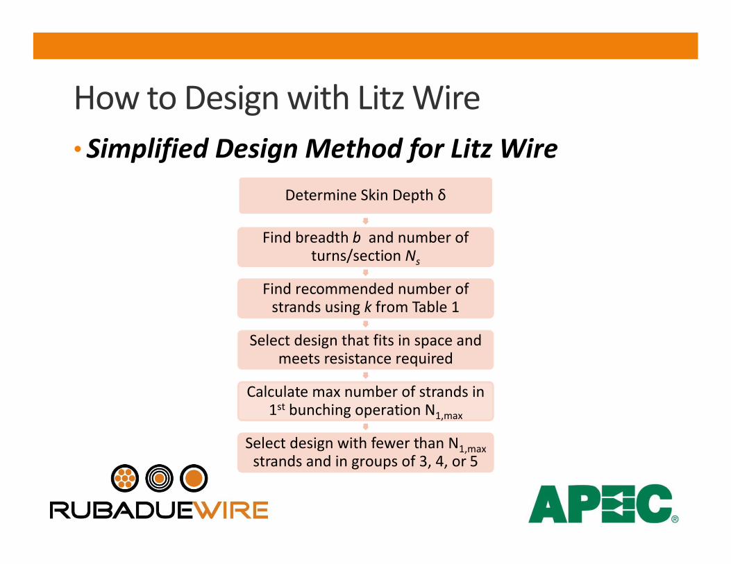
• Simplified Design Method for Litz Wire
How to Design with Litz Wire
Determine Skin Depth δ
Find breadth b and number of turns/section Ns
Find recommended number of strands using k from Table 1
Select design that fits in space and meets resistance required
Calculate max number of strands in 1st bunching operation N1,max
Select design with fewer than N1,max strands and in groups of 3, 4, or 5
How to Design with Litz Wire
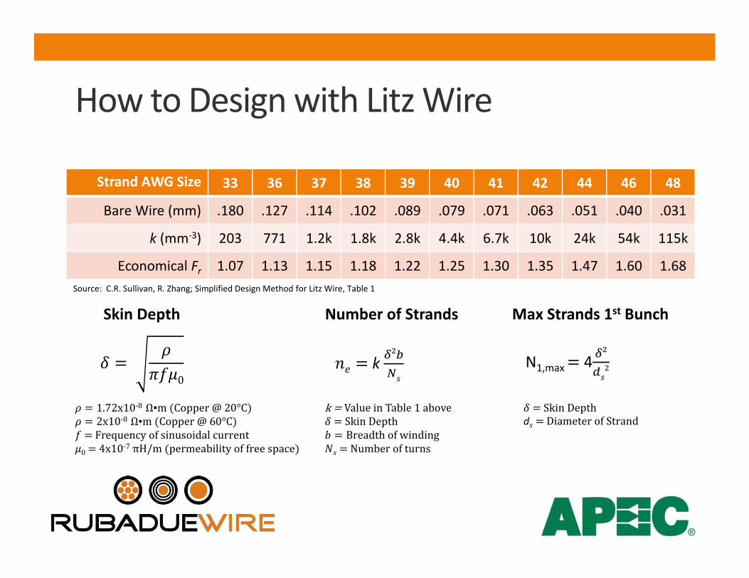
Strand AWG Size 33 36 37 38 39 40 41 42 44 46 48
Bare Wire (mm) .180 .127 .114 .102 .089 .079 .071 .063 .051 .040 .031
k (mm-3) 203 771 1.2k 1.8k 2.8k 4.4k 6.7k 10k 24k 54k 115k
Economical Fr 1.07 1.13 1.15 1.18 1.22 1.25 1.30 1.35 1.47 1.60 1.68Source: C.R. Sullivan, R. Zhang; Simplified Design Method for Litz Wire, Table 1
0
Skin Depth
= 1.72x10⁻⁸ Ω▪m (Copper @ 20°C)= 2x10⁻⁸ Ω▪m (Copper @ 60°C)= Frequency of sinusoidal current0 = 4x10⁻⁷ πH/m (permeability of free space)
k
Number of Strands
k = Value in Table 1 above= Skin Depth= Breadthofwinding= Number of turns
N1,max 4
Max Strands 1st Bunch
= Skin Depthd = Diameter of Strand
•Select Design that fits in space• The number strands calculation should be treated as a
guideline. Strand counts can deviate up to +/- 25% without negative effect.
• Most suppliers will have a chart of various constructions with nominal diameters and resistance values.
• Evaluate various constructions for acceptable performance.
How to Design with Litz Wire
•Costing• Be aware, moving from a solid wire to Litz WILL
impact raw material unit cost.• How much impact is design / supplier dependent.• By evaluating various Litz constructions in a given
winding, you can perform simple cost-benefit analysis.
How to Design with Litz Wire
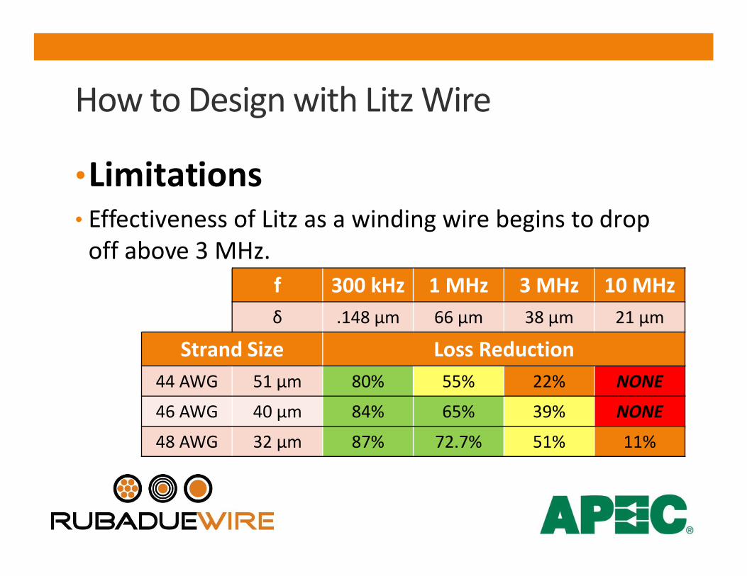
•Limitations• Effectiveness of Litz as a winding wire begins to drop
off above 3 MHz.
How to Design with Litz Wire
f 300 kHz 1 MHz 3 MHz 10 MHzδ .148 µm 66 µm 38 µm 21 µm
Strand Size Loss Reduction44 AWG 51 µm 80% 55% 22% NONE
46 AWG 40 µm 84% 65% 39% NONE
48 AWG 32 µm 87% 72.7% 51% 11%

•Limitations• Packing Factor / Copper Density are affected due to
the enamel layer and the inherent air gaps from twisting round wires together in multiple operations.
• The manufacturing process can damage the enamel layer on individual strands. The use of protective layers such as textile serves, tapes, or extruded isolation layers may be needed.
How to Design with Litz Wire

• Dartmouth Power Electronics and Magnetic Components Group web site:• http://thayer.dartmouth.edu/inductor/index.shtml
• C.R. Sullivan and R. Y. Zhang, “Simplified Design Method for Litz Wire”, IEEE Applied Power Electronics Conference, 2014
• C. R. Sullivan, “Windings for High Frequency Applications”, APEC Industry Session Presentation, 2014
Resource Materials & Citations
