a practical approach to upstream rf signal management in hfc networks
TRANSCRIPT

8/18/2019 A Practical Approach to Upstream RF Signal Management in HFC Networks
http://slidepdf.com/reader/full/a-practical-approach-to-upstream-rf-signal-management-in-hfc-networks 1/28
SCTE Autumn Lecture Meeting
27 September 2005, IEE, London
Janhein van BrienenPrincipal Engineer Telewest Broadband
A Practical Approach to Upstream RF signalManagement in HFC Networks

8/18/2019 A Practical Approach to Upstream RF Signal Management in HFC Networks
http://slidepdf.com/reader/full/a-practical-approach-to-upstream-rf-signal-management-in-hfc-networks 2/28
Slide 227/09/2005
Historical Context
• Evolution of Telewest Broadband HFC networks
– Today's Telewest Broadband is the result of a series of mergers and acquisitions.
• Consequences of this process
– Some 10 distinctly different architectures can be identified inthe Telewest Broadband HFC networks.
– Most vendors equipment is represented somewhere withinthe Telewest Broadband network.
– The regionalised character of Telewest Broadband hasresulted in different practises and approaches in theoperational environment.
8/18/2019 A Practical Approach to Upstream RF Signal Management in HFC Networks
http://slidepdf.com/reader/full/a-practical-approach-to-upstream-rf-signal-management-in-hfc-networks 3/28
Slide 327/09/2005
Historical Context
• Pre 2000 upstream network usage and status
– RF IPPV - simple and robust BPSK modulation schemetransferring very small amounts of data.
– Upstream calibration and data collection process best
described as organised chaos.– Network monitoring - Upstream FSK data carrier with
transponders answering a poll request.
– First use of 2-way sweep and network alignment equipment.– Most networks reverse path capable, but some not
maintained or equipment not commissioned.
8/18/2019 A Practical Approach to Upstream RF Signal Management in HFC Networks
http://slidepdf.com/reader/full/a-practical-approach-to-upstream-rf-signal-management-in-hfc-networks 4/28Slide 427/09/2005
Historical Context
• Post 2000 upstream network
– Preparation for DTV and DOCSIS started in 1999– Complete rework of return path combining in Hub sites and
Headends.
– Testing and removal of “non digital-ready” passives from thenetwork. (mainly splitters and isolators)
– Assessment of return path network performance required to
ensure meeting DOCSIS demands.– Re-commissioning of return path and verification of
upstream network performance.
8/18/2019 A Practical Approach to Upstream RF Signal Management in HFC Networks
http://slidepdf.com/reader/full/a-practical-approach-to-upstream-rf-signal-management-in-hfc-networks 5/28Slide 527/09/2005
Historical Context
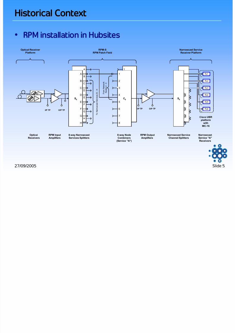
• RPM installation in Hubsites
S8
A
B
C
D
E
F
G
H
C8
1
2
3
4
5
6
7
8
S8
C8
8-way Node
Combiners
(Service "A")
8-way Narrowcast
Services Splitters
1
2
3
4
5
6
7
8
A
B
C
D
E
F
G
H
Narrowcast Service
Channel Splitters
Narrowcast
Service "A"
Receivers
T o N a r r o w c a s t S e r v i c e s B - H
RPM Output
Amplifiers
RPM-S
RPM Patch Field
Optical Receiver
Platform
Narrowcast Service
Receiver Platform
Cisco UBR
platformwith
MC-16
RPM Input
Amplifiers
Rx1
Rx2
Rx3
Rx4
f U1
f U2
F r o m
N e t w o r k
N o d e s 2 - 4
Rx5
Rx6
Optical
Receivers
f U3
f U1
f U2
f U3
I/P TP O/P TPI/P TP O/P TP
S8

8/18/2019 A Practical Approach to Upstream RF Signal Management in HFC Networks
http://slidepdf.com/reader/full/a-practical-approach-to-upstream-rf-signal-management-in-hfc-networks 6/28Slide 627/09/2005
Upstream Network and Equipment Performance
• Downstream Network Performance Assessment
O
E
Intermediate
Amplifier Fibre Node
Star TapsWith Drop Cables
Distribution
Amplifier
O
E
Hub site

8/18/2019 A Practical Approach to Upstream RF Signal Management in HFC Networks
http://slidepdf.com/reader/full/a-practical-approach-to-upstream-rf-signal-management-in-hfc-networks 7/28
Slide 727/09/2005
O
E
Intermediate
Amplifier Fibre Node
Star TapsWith Drop Cables
Distribution
Amplifier
O
E
Hub site
Upstream Network and Equipment Performance
• Upstream Network Performance Assessment

8/18/2019 A Practical Approach to Upstream RF Signal Management in HFC Networks
http://slidepdf.com/reader/full/a-practical-approach-to-upstream-rf-signal-management-in-hfc-networks 8/28
Slide 827/09/2005
Upstream Network and Equipment Performance
• Network Performance Assessment
– Amplifiers generally not a problem - wide dynamic range andnoise performance ensures trouble free operation.
– Legacy Fibre Optic equipment poorly specified or not at all
documented - undesirable interoperability issues noted.– Upstream HFC network set-up different in most networks,
even between identical equipment.
– Conclusion: not possible to implement a uniform DOCSISservice in such an environment.

8/18/2019 A Practical Approach to Upstream RF Signal Management in HFC Networks
http://slidepdf.com/reader/full/a-practical-approach-to-upstream-rf-signal-management-in-hfc-networks 9/28
Slide 927/09/2005
Upstream Network and Equipment Performance
• Testing Requirements
– Common test standard required to assess performance of alloptical equipment combinations.
– Referencing all test results against a common standard
which meets DOCSIS requirements with acceptable margin.– Translation of test results into spectrum utilisation to future
proof against changes in service requirements.
– Common standard required for commissioning equipmentacross all regions to ensure uniform DOCSIS performance.

8/18/2019 A Practical Approach to Upstream RF Signal Management in HFC Networks
http://slidepdf.com/reader/full/a-practical-approach-to-upstream-rf-signal-management-in-hfc-networks 10/28
Slide 1027/09/2005
– Uses a 32 MHz wide noise signal with a notch at 22.5 MHz– Measures the DUT noise input power in dBmV/Hz vs. the
noise floor to noise envelope ∆ in dB at the DUT output.
– Is repeated at 5 different temperatures to assessperformance over the operational temperature range.
– Is measured at the optical transmitter input
Upstream Network and Equipment Performance
• “Noise in the Notch” test adopted
White Noise
Generator Bandpass and
22.5Mhz Notch Filter
Precision Step
Attenuator Bandpass
Filter
Spectrum
Analyser
System Under Test (SUT)
Opt. Transmitter, 20Km Fibre and Opt. Receiver
P(f)O
E
G
dB
E
O

8/18/2019 A Practical Approach to Upstream RF Signal Management in HFC Networks
http://slidepdf.com/reader/full/a-practical-approach-to-upstream-rf-signal-management-in-hfc-networks 11/28
Slide 1127/09/2005
Noise in the Notch Bandpass and Notch Measurement Filter
Mkr 1
- 3 . 0 d B
Mkr 2
0 . 2 d B Mkr 3
- 3 . 0 d B
Mkr 4
- 5 4 . 5 d B
Mkr 5
- 3 . 0 d B
Mkr 6
- 3 . 0 d B
-60
-55
-50
-45
-40
-35
-30
-25
-20
-15
-10
-5
0
5
1.0 7.0 13.0 19.0 25.0 31.0 37.0 43.0 49.0 55.0 61.0
Frequency (MHz)
I n s e r t i o
n l o s s ( d B )
Filter responseMarker 1, 4.0MhzMarker 2, 17.5MhzMarker 3, 20.2MhzMarker 4, 22.5MhzMarker 5, 25.3MhzMarker 6, 42.1Mhz
Upstream Network and Equipment Performance

8/18/2019 A Practical Approach to Upstream RF Signal Management in HFC Networks
http://slidepdf.com/reader/full/a-practical-approach-to-upstream-rf-signal-management-in-hfc-networks 12/28
Slide 1227/09/2005
Noise in the Notch Spectum Analyser Filter
Mkr 1
- 5 . 5 d B
Mkr 2
- 0 . 3 d B
Mkr 3
- 0 . 3 d B
Mkr 4
- 5 . 0 d B
-60
-55
-50
-45
-40
-35
-30
-25
-20
-15
-10
-5
0
5
1.0 7.0 13.0 19.0 25.0 31.0 37.0 43.0 49.0 55.0 61.0
Frequency (MHz)
I n s e r t i o
n l o s s ( d B )
Filter response
Marker 1, 15.1Mhz
Marker 2, 17.5Mhz
Marker 3, 22.5Mhz
Marker 4, 25.3Mhz
Upstream Network and Equipment Performance

8/18/2019 A Practical Approach to Upstream RF Signal Management in HFC Networks
http://slidepdf.com/reader/full/a-practical-approach-to-upstream-rf-signal-management-in-hfc-networks 13/28
Slide 1327/09/2005
Noise in the slot test set-up system response
Mkr 1
- 5 4 . 2 d B
Mkr 2
- 0 . 5 d B Mkr 3
- 3 . 6 d B
Mkr 4
- 5 4 . 8 d B
Mkr 5
- 7 . 7 d B
Mkr 6
- 4 1 . 1 d B
-60
-55
-50
-45
-40
-35
-30
-25
-20
-15
-10
-5
0
5
1.0 7.0 13.0 19.0 25.0 31.0 37.0 43.0 49.0 55.0 61.0
Frequency (MHz)
I n s e r t i o n l o s s ( d B )
Overall responseMarker 1, 15.5MhzMarker 2, 17.5MhzMarker 3, 20.2MhzMarker 4, 22.5MhzMarker 5, 25.3MhzMarker 6, 42.1Mhz
Upstream Network and Equipment Performance
8/18/2019 A Practical Approach to Upstream RF Signal Management in HFC Networks
http://slidepdf.com/reader/full/a-practical-approach-to-upstream-rf-signal-management-in-hfc-networks 14/28
Slide 1427/09/2005
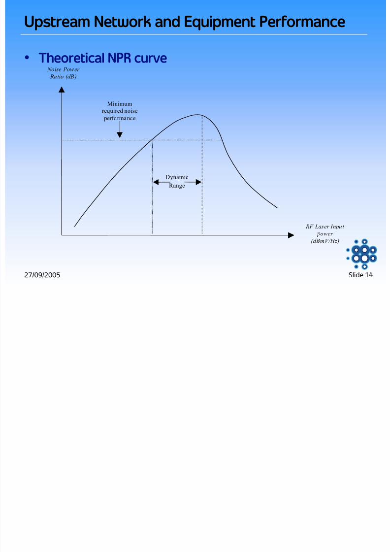
• Theoretical NPR curve Noise Power
Ratio (dB)
RF Laser Input
ower
(dBmV/Hz)
Dynamic
Range
Minimum
required noise
performance
Upstream Network and Equipment Performance

8/18/2019 A Practical Approach to Upstream RF Signal Management in HFC Networks
http://slidepdf.com/reader/full/a-practical-approach-to-upstream-rf-signal-management-in-hfc-networks 15/28
Slide 1527/09/2005
Noise Power Ratio vs RF Input SA RT-1 TX - HL 2220 RX @ 8dB OLB
20.0
25.0
30.0
35.0
40.0
45.0
-51 -50 -49 -48 -47 -46 -45 -44 -43 -42 -41 -40 -39 -38 -37 -36 -35 -34 -33 -32
TX Input level (dBmV/Hz)
N P R ( d B )
Temp -10°C/05°C
Temp 00°C/17°C
Temp 20°C/36°C
Temp 40°C/57°C
Temp 60°C/77°C
Temp 75°C/92°C
Upstream Network and Equipment Performance
• Actual NPR curve

8/18/2019 A Practical Approach to Upstream RF Signal Management in HFC Networks
http://slidepdf.com/reader/full/a-practical-approach-to-upstream-rf-signal-management-in-hfc-networks 16/28
Slide 1627/09/2005
Upstream Network and Equipment Performance
• Application of results
– Measurement results expressed in “Power per Hertz” enableeasy translation to signals of different bandwidths.
– Current 3.2MHz upstream DOCSIS carrier operating point inprevious example is found by considering the measuredresult of -45dBmV/Hz + 10*LOG(3200000)Hz = 20dBmV.
– To find the RF input level to the fibre node station ports therecommended gain or attenuation setting of the node mustbe considered. This is labelled Node Return Gain (NRG)

8/18/2019 A Practical Approach to Upstream RF Signal Management in HFC Networks
http://slidepdf.com/reader/full/a-practical-approach-to-upstream-rf-signal-management-in-hfc-networks 17/28
Slide 1727/09/2005
Upstream Network and Equipment Performance
• Application of results
– NRG is calculated to achieve the most beneficial upstreamCPE transmit power when considering cable and passiveattenuation between the final distribution node and thehome in the HFC network.
– The upstream network gain (input of distribution node toinput of fibre node) is normally 0.
– NRG is documented for all nodes in use in Telewest in theRPM calculator.

8/18/2019 A Practical Approach to Upstream RF Signal Management in HFC Networks
http://slidepdf.com/reader/full/a-practical-approach-to-upstream-rf-signal-management-in-hfc-networks 18/28
Slide 1827/09/2005
Upstream Network and Equipment Performance
• Example of Fibre Node alignment
-1dB
20dB
Test Point
25 dBmV
@ Station Port
17 dBmV 32 dBmV
PassiveCombining
Loss
-6.3dB-0.7dB
H
L
Amplifier Module
+19dB -3dB
SA 6920 RT-1
-3 dB
Test
Probe
40 dBmV
@ Injection
Point
For Alignment, Adjust O/P Pad to Achieve NRG of +7dB.
PAD
20dB
Test Point
-1dB
SA
Probe
Main O/P T.P Reverse O/P
T.P.

8/18/2019 A Practical Approach to Upstream RF Signal Management in HFC Networks
http://slidepdf.com/reader/full/a-practical-approach-to-upstream-rf-signal-management-in-hfc-networks 19/28
Slide 1927/09/2005
Upstream Network and Equipment Performance
• Upstream alignment
– RPM calculator tool allows independent calculation of DOCSISdata carriers and CW alignment carriers - long establishedpractises may remain unchanged.
– RPM calculator input data can be selected from 6 simple dropdown menus.
– Undesirable equipment combinations will not calculateresults.
– Calculator tool is updated whenever new equipment isintroduced in the network.

8/18/2019 A Practical Approach to Upstream RF Signal Management in HFC Networks
http://slidepdf.com/reader/full/a-practical-approach-to-upstream-rf-signal-management-in-hfc-networks 20/28
Slide 2027/09/2005
Upstream Network and Equipment Performance
• RPM calculatorEnter optical node
Type
Alignment Level
(dBmV) on laser IP Enter Rx Type
Enter Normalised
O/P on RX (dBmV)
Enter Bandwidth
of Carrier (MHz)
input Amplifier
gain =
output Amplifier
gain =
Node Return Gain = 7 dB 6 dB 14 dB
Node IP Alignment CW(dBmV)
Level presented to laserTP* (dBmV)
Alignment CW(dBmV)
Alignment CW(dBmV)
Alignment CW(dBmV)
Alignment CW(dBmV)
25 32 27 33 27 17
Digital signal Level
(dBmV)
Digital signal Level
(dBmV)
Digital signal Level
(dBmV)
Digital signal Level
(dBmV)
Digital signal Level
(dBmV)
Digital signal Level
(dBmV)
13 20 15 21 15 5
Optical node type: Optical laser type:Optical receiver model
and type
SA 6920 SA RT-1 (-7dBm) HLW 2220 or 21105.0 dBmV for a bandwidth of 3.2
Enter return laser make and type
RX
Note: Set Expected Ubr level to:
Rev TX IPNode RF mother board
SA RT-1 (-7dBm)
HLW 2220 or 211032 27 3.2
RPM
Patchfield
MC-16
8-way
input splitter
UBr
SA 6920

8/18/2019 A Practical Approach to Upstream RF Signal Management in HFC Networks
http://slidepdf.com/reader/full/a-practical-approach-to-upstream-rf-signal-management-in-hfc-networks 21/28
Slide 2127/09/2005
Upstream Network and Equipment Performance
• NPR test only part of fibre node tests.
– Temperature stability further tested by sweeping the fullupstream path at temperature points with a networkanalyser.
– Optical transmitter modules monitored for optical poweroutput, temperature and laser bias voltage test point.
– Test data forms part of full downstream testing and powersupply testing, which is performed on every fibre node.

8/18/2019 A Practical Approach to Upstream RF Signal Management in HFC Networks
http://slidepdf.com/reader/full/a-practical-approach-to-upstream-rf-signal-management-in-hfc-networks 22/28
Slide 2227/09/2005
1.6MHz to 3.2MHz upstream carrier upgrade
• 3.2 MHz DOCSIS carriers included in original design.
– Upgrade required an extra 3dB of Upstream transmit powerform all CPE devices.
– In practise larger transmit power swings may be seen due tothe default adjustment threshold of 1dB on the Cisco UBR
– RPM calculator showed that 1 fibre node type hadinsufficient Node Return Gain to accommodate this.
– Optical transmitters in these nodes were upgraded to highergain types enabling upgrade rollout without furtherproblems.

8/18/2019 A Practical Approach to Upstream RF Signal Management in HFC Networks
http://slidepdf.com/reader/full/a-practical-approach-to-upstream-rf-signal-management-in-hfc-networks 23/28
Slide 2327/09/2005
3.2 QPSK to 16QAM upgrade
• Problems with DOCSIS specification.
– CPE upstream transmit power
• +8 to +58 dBmV (QPSK) but +8 to +55 dBmV (16QAM).
– Most legacy Cable Modems follow DOCSIS specification,DHT’s generally don’t.
– RPM calculator shows that 1 fibre node type (ANTEC 1FTD)has insufficient Node Return Gain to compensate for thisdrop by providing an extra 5 or 6dB Gain.
– Therefore Carrier to Ingress will decrease by 3dB, as willnoise performance over the optical system.
2 QPSK 16QAM d

8/18/2019 A Practical Approach to Upstream RF Signal Management in HFC Networks
http://slidepdf.com/reader/full/a-practical-approach-to-upstream-rf-signal-management-in-hfc-networks 24/28
Slide 2427/09/2005
3.2 QPSK to 16QAM upgrade
• Theoretical 1FTD area CPE TX power calculation
– With subscriber tap values and max number of CPE per dropcable, min and maximum attenuation levels can be calculated.
– The 1FTD requires 21dBmV for 3.2MHz carriers on eachstation port. The maximum passive attenuation is 39dB, theminimum is 12dB. Therefore the CPE TX power willtheoretically range between 33 and 60dBmV.
– Theoretical average upstream level therefore is 46.5dBmV.
– The Cisco UBR default “continuation” threshold of ± 2dBenables Cable Modems transmitting at 58dBmV to register.
3 2 QPSK 16QAM d

8/18/2019 A Practical Approach to Upstream RF Signal Management in HFC Networks
http://slidepdf.com/reader/full/a-practical-approach-to-upstream-rf-signal-management-in-hfc-networks 25/28
Slide 2527/09/2005
3.2 QPSK to 16QAM upgrade
• 1FTD area UBR pollCPE Upstream Transmit levels UBR01 Edinburgh 12th of July
0
50
100
150
200
250
300
350
400
450
20 25 30 35 40 45 50 55 60
Upstream Transmit level (dBmV)
N u m b e r o f d e v i c e s
Edinburgh totals
47.5
3 2 QPSK t 16QAM d

8/18/2019 A Practical Approach to Upstream RF Signal Management in HFC Networks
http://slidepdf.com/reader/full/a-practical-approach-to-upstream-rf-signal-management-in-hfc-networks 26/28
Slide 2627/09/2005
3.2 QPSK to 16QAM upgrade
• 1FTD area UBR poll
– Theoretical calculation matches the UBR poll almost exactly.
– CPE upstream TX curve sits too high in the power range of the CPE equipment.
– If no action was taken and the QPSK to 16QAM switch wasmade some 7% of Cable modems would no longer be able toregister on this UBR
– Further analysis by CPE type reveals that the upturn in thecurve at 58dBmV is due to devices at their maximum TXlevel, but not achieving requested UBR receive level.
3 2 QPSK t 16QAM d

8/18/2019 A Practical Approach to Upstream RF Signal Management in HFC Networks
http://slidepdf.com/reader/full/a-practical-approach-to-upstream-rf-signal-management-in-hfc-networks 27/28
Slide 2727/09/2005
3.2 QPSK to 16QAM upgrade
• 1FTD upgrade solution
– A replacement fibre optic transmitter with a minimum of 6dBextra gain has been developed by one of Telewest’s currentsuppliers and is currently under evaluation as a replacementof the original RDL-2 transmitter.
– When approved this should remove one of the mainequipment obstacles preventing an upgrade to 16QAM
Questions

8/18/2019 A Practical Approach to Upstream RF Signal Management in HFC Networks
http://slidepdf.com/reader/full/a-practical-approach-to-upstream-rf-signal-management-in-hfc-networks 28/28
Slide 2827/09/2005
Questions
• Thank you for your attention