a position detection strategy for sensorless surface mounted permanent magnet motors at low speed...
TRANSCRIPT

A Position Detection Strategy for Sensorless Surface Mounted Permanent
Magnet Motors at Low Speed Using Transient Finite-Element Analysis
Zhao Wang , Shuangxia Niu, S. L. Ho , W. N. Fu, and Jianguo ZhuIEEE TRANSACTIONS ON MAGNETICS, VOL. 48, NO. 2,P.1003-1006, FEBRUARY 2012
Student ID:MA120104Student:Chien-Ming Huan

ABSTRACT
A novel solution for sensorless starting of conventional surface mounted PM motors is proposed.
The strategy of the proposed scheme is to creatively formulate a combination of electromagnetic field with transient finite element method (FEM).

INTRODUCTION 1/4
The permanent magnet (PM) brushless machine is widely used in industry by virtue of its high efficiency and high torque/power density. However, conventional PM brushless machine always requires rotor position information in order to operate satisfactorily.

INTRODUCTION 2/4
Unfortunately, there are many drawbacks in these sensors, such as limited temperature operation, limited speed, increased cost/size and complexity of system which degrades the overall performance and reliability of the system.
To reduce cost and system complexity, sensorless control technology is investigated extensively. Among the various sensorless techniques, the zero and very low speed position estimation is one of the most challenging topics for researchers.

INTRODUCTION 3/4
It is well-known that when the motor is running at mid-speed range, the back electro-motive force (EMF) induced in the windings can be used for rotor position estimation.
When the motor is at standstill, there is however no back EMF induced in the windings, and hence a startup algorithm or an initial rotor position detection method is required in order to start the motor reliably from standstill up to the minimum speed.

INTRODUCTION 4/4
The most popular sensorless control method for starting and low speed operation is based on injecting a voltage signal into the phase windings and measures the resultant high frequencyinduced signal.

ADVANTAGES 1/2
FEM is utilized to investigate a complete motor model,and hence developing a solid theory-based motor control strategy.
The research also improves the signal injection strategy,simplifies the implementation and eliminates the need for polarity detection and hence offering a simple control drive.

ADVANTAGES 2/2
The biggest merit is that it utilizes the saliency that surface mounted PM motor originally possesses, thus eliminating the requirement to modify the rotor structure. This has largely increased the practicability of this strategy because it can be realized in most commonly used PM motors.

NUMERICAL SIMULATION 1/9
The computation is based on a numerical simulation that uses transient FEM on a common Brushless DC motor model.

NUMERICAL SIMULATION 2/9One of the three phase windings, in this case, Phase A, is used as the signal injection winding. A voltage signalis applied to the terminals of Phase A andneutral wire. The voltage between Phase B and the neutral wire,
NUMERICAL SIMULATION 3/9
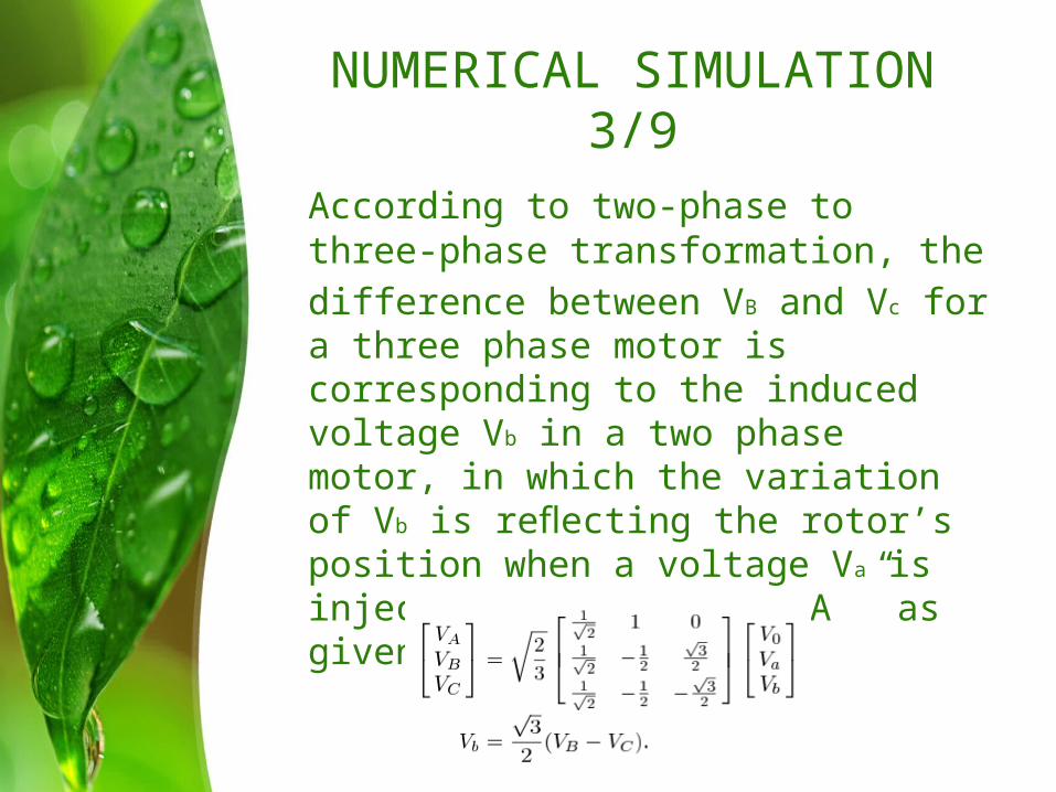
According to two-phase to three-phase transformation, thedifference between VB and Vc for a three phase motor is corresponding to the induced voltage Vb in a two phase motor, in which the variation of Vb is reflecting the rotor’s position when a voltage Va is injected into winding “A ” as given below:

NUMERICAL SIMULATION 4/9

NUMERICAL SIMULATION 5/9

NUMERICAL SIMULATION 6/9Since VB and VC are always in phase,
it makes sense to subtract their amplitudes at different rotor position angles and the variation of their difference against the rotor position is plotted in Fig. 7.
NUMERICAL SIMULATION 7/9
The solution for this problem is to inject the same signal from another phase winding to, for instance, Phase B. Then the difference between the induced voltages VB and VC is measured as VCA. VCA has a 120 shift from VBC, and the combination of these two quantities would then provide adequate information for rotor position detection

NUMERICAL SIMULATION 8/9

NUMERICAL SIMULATION 9/9

EXPERIMENT RESULTS 1/2
To verify the simulation results ,experiments are carried out.A motor that has the same specifications as in the simulation is used. A function generator is used as the signal source to inject
into Phase A. Two channels from an oscilloscope are connected to the other two phase windings of the motor.

EXPERIMENT RESULTS 2/3

CONCLUSIONBy observing the difference
between the induced voltages,one can determine the rotor position as well and solving the polarity detection problem simultaneously. In summary, this research has successfully deduced a position detection strategy which can be easily incorporated in the development of a novel sensorless starting scheme for a BLDC motor using FEM. The implementation of the algorithm is simple and hence the controller cost is substantially reduced.