a portable high-frequency square-wave oscillograph for television
TRANSCRIPT
A Portable High-Frequency Square-Wave Oscillographfor Television *
R. D. KELLt, ASSOCIATE I.R.E., A. V. BEDFORDt, ASSOCIATE, I.R.E.,
AND H. N. KOZANOWSKIt, ASSOCIATE, I.R.E.
Summary-A portable high-frequency oscillograph for televisionis described by which a square-wave (100-kilocycle) response may beviewed as a dotted wave and readily recorded as a series of readings.The dots are spaced at 1/30- (or 1/20-) microsecond intervals. No elec-trical connection is required between the oscillograph and the square-wave generator other than that established through the apparatus undertest since the synchronous sweep and timing dots are derived from thesquare-wave response of the apparatus. Circuit diagrams of the square-wave generator and square-wave oscillograph are given.
I. INTRODUCTION
HE applications of square-wave measurementsT in television are developed in detail in a com-
panion paper' in which the following aspectsare treated: (1) a graphical chart method for analyzingthe response of a system to a square-wave input signalto obtain the sine-wave amplitude and delay charac-teristics; (2) a graphical chart method for synthesizingthe response to a square-wave from the sine-waveamplitude and delay characteristics; (3) a method forevaluating the mean steepness of a transient-responsewave in terms of the width of blur produced in a tele-vision image by a visually equivalent wave having alinear change between two reference half tones; and(4) specific applications of square-wave measurements.When an experimentally determined square-waveresponse is required for the execution of items (1), (3),and (4), the use of a suitable oscillograph becomesnecessary. It is the purpose of the present paper todescribe a portable high-frequency oscillograph and asquare-wave generator by which a square-wave re-sponse may be viewed as a dotted wave and readilyrecorded as a series of amplitude readings separated byknown equal time intervals.
II. CHOICE OF THE FUNDAMENTAL FREQUENCYOF THE SQUARE WAVE
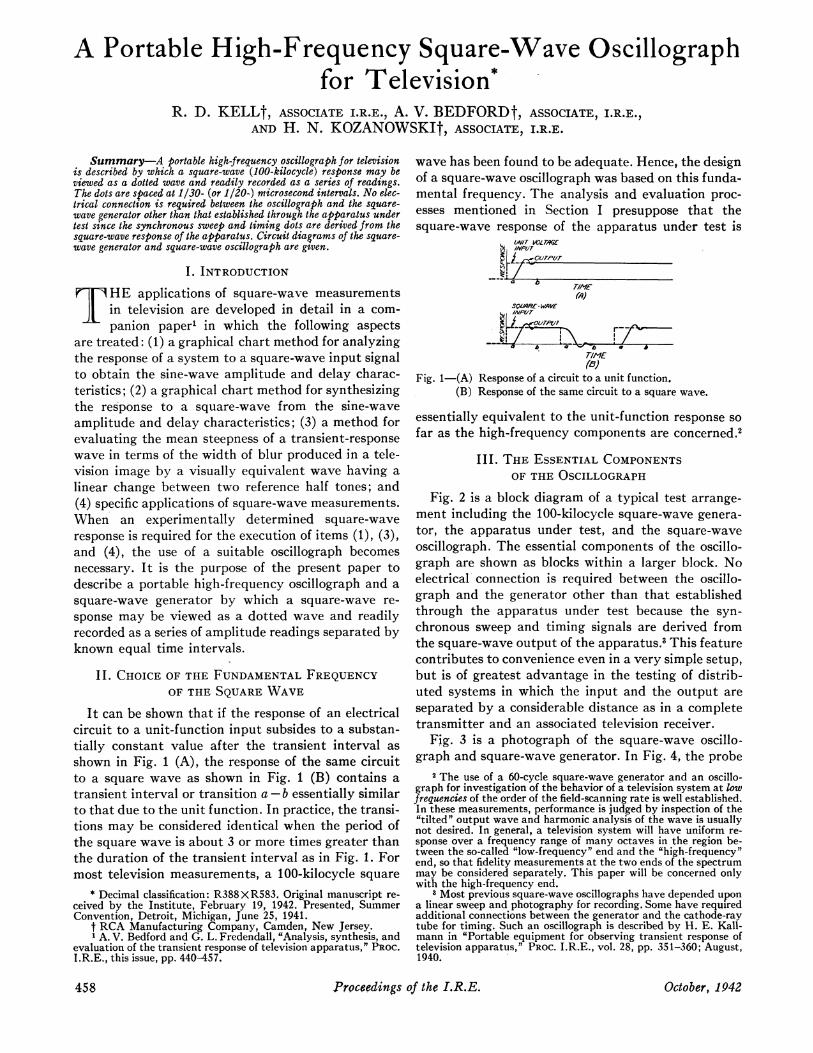
It can be shown that if the response of an electricalcircuit to a unit-function input subsides to a substan-tially constant value after the transient interval asshown in Fig. 1 (A), the response of the same circuitto a square wave as shown in Fig. 1 (B) contains atransient interval or transition a - b essentially similarto that due to the unit function. In practice, the transi-tions may be considered identical when the period ofthe square wave is about 3 or more times greater thanthe duration of the transient interval as in Fig. 1. Formost television measurements, a 100-kilocycle square
* Decimal classification: R388XR583. Original manuscript re-ceived by the Institute, February 19, 1942. Presented, SummerConvention, Detroit, Michigan, June 25, 1941.
t RCA Manufacturing Company, Camden, New Jersey.1 A. V. Bedford and G. L. Fredendall, "Analysis, synthesis, and
evaluation of the transient response of television apparatus," PROC.I.R.E., this issue, pp. 440-457.
wave has been found to be adequate. Hence, the designof a square-wave oscillograph was based on this funda-mental frequency. The analysis and evaluation proc-esses mentioned in Section I presuppose that thesquare-wave response of the apparatus under test is
1/NIT VOLTAI9GOUAP117,
IMP/ITTIM
III IVITH ESNILCMO NT
-
(B)Fig. 1- (A) Response of a circuit to a unit function.
(B) Response of the same circuit to a square wave.
essentially equivalent to the unit-function response sofar as the high-frequency components are concerned.2
III. THE ESSENTIAL COMPONENTSOF THE OSCILLOGRAPH
Fig. 2 is a block diagram of a typical test arrange-ment including the 100-kilocycle square-wave genera-tor, the apparatus under test, and the square-waveoscillograph. The essential components of the oscillo-graph are shown as blocks within a larger block. Noelectrical connection is required between the oscillo-graph and the generator other than that establishedthrough the apparatus under test because the syn-chronous sweep and timing signals are derived fromthe square-wave output of the apparatus.3 This featurecontributes to convenience even in a very simple setup,but is of greatest advantage in the testing of distrib-uted systems in which the input and the output areseparated by a considerable distance as in a completetransmitter and an associated television receiver.
Fig. 3 is a photograph of the square-wave oscillo-graph and square-wave generator. In Fig. 4, the probe
2 The use of a 60-cycle square-wave generator and an oscillo-graph for investigation of the behavior of a television system at lowfrequencies of the order of the field-scanning rate is well established.In these measurements, performance is judged by inspection of the'tilted" output wave and harmonic analysis of the wave is usuallynot desired. In general, a television system will have uniform re-sponse over a frequency range of many octaves in the region be-tween the so-called "low-frequency" end and the "high-frequency"end, so that fidelity measurements at the two ends of the spectrummay be considered separately. This paper will be concerned onlywith the high-frequency end.
3 Most previous square-wave oscillographs have depended upona linear sweep and photography for recording. Some have requiredadditional connections between the generator and the cathode-raytube for timing. Such an oscillograph is described by H. E. Kall-mann in "Portable equipment for observing transient response oftelevision apparatus," PROC. I.R.E., vol. 28, pp. 351-360; August,1940.
Proceedings of the I.R.E.458 October, 1942
Kell, Bedford, and Kozanowski: Oscillograph for Television
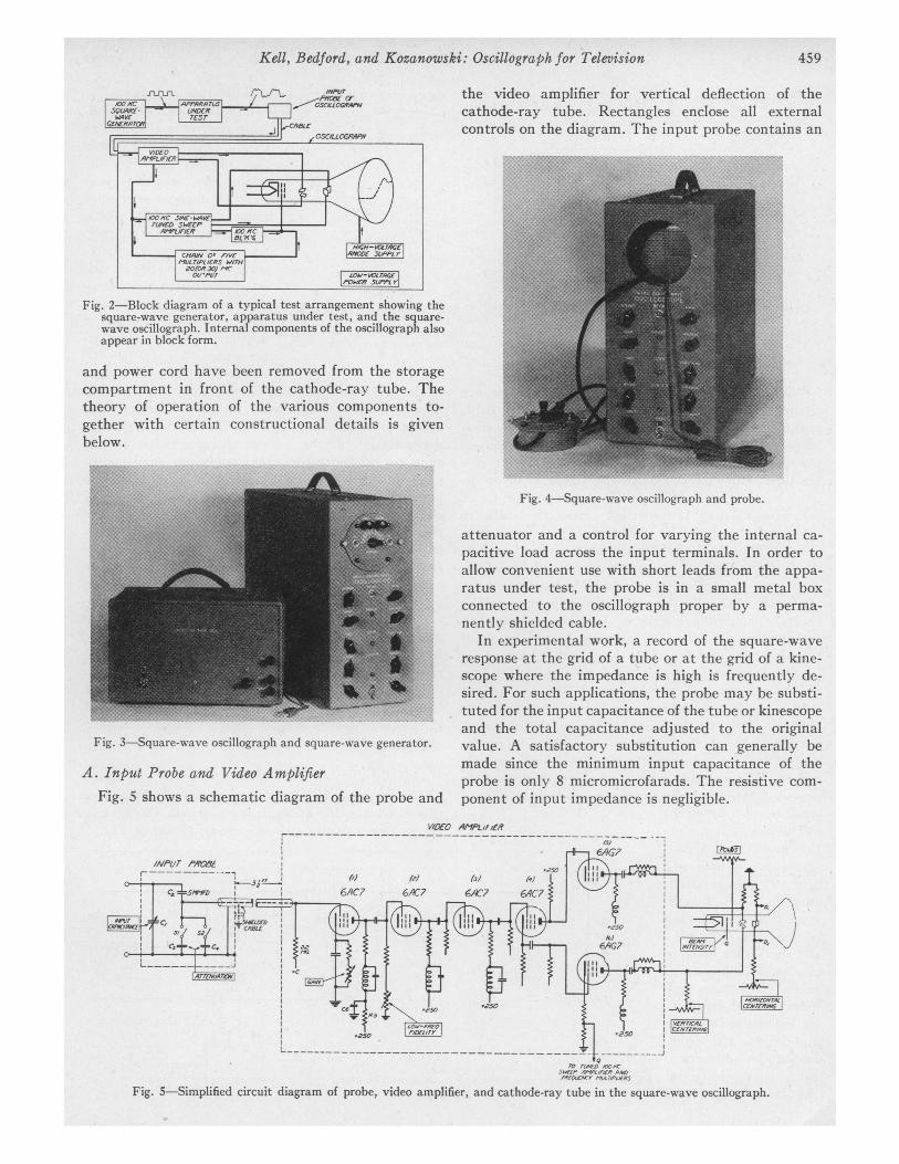
the video amplifier for vertical deflection of thecathode-ray tube. Rectangles enclose all externalcontrols on the diagram. The input probe contains an
Fig. 2-Block diagram of a typical test arrangement showing thesquare-wave generator, apparatus under test, and the square-wave oscillograph. Internal components of the oscillograph alsoappear in block form.
and power cord have been removed from the storagecompartment in front of the cathode-ray tube. Thetheory of operation of the various components to-gether with certain constructional details is givenbelow.
Fig. 4-Square-wave oscillograph and probe.
Fig. 3-Square-wave oscillograph and square-wave generator.
A. Input Probe and Video AmplifierFig. 5 shows a schematic diagram of the probe and
attenuator and a control for varying the internal ca-pacitive load across the input terminals. In order toallow convenient use with short leads from the appa-ratus under test, the probe is in a small metal boxconnected to the oscillograph proper by a perma-nently shielded cable.
In experimental work, a record of the square-waveresponse at the grid of a tube or at the grid of a kine-scope where the impedance is high is frequently de-sired. For such applications, the probe may be substi-tuted for the input capacitance of the tube or kinescopeand the total capacitance adjusted to the originalvalue. A satisfactory substitution can generally bemade since the minimum input capacitance of theprobe is only 8 micromicrofarads. The resistive com-ponent of input impedance is negligible.
V/tWO A^Pb,f,fR,-
6AG?i ,,,
(M,)t, () l )6AC7 6A7 6A7 6,IC?
N ~~~~~~~~iiI6 ~ *
I.'~~~~~~~l-~~6%G7v .tS ,~~~~~~~~~~~~~~~~~~~~~~~~~~~~~~~~~~~~~~~~~~~~~~~~~~~~~~~~~~~~~~~~~~~~~~~~~~~~~~~~~~~~~~~~~~~~~~~~~~~~~~~~~~~~~~~~~~~~~~~~~~~~~~~~~~~~~~~
Fig. 5-Simplified circuit diagram of probe, video amplifier, and cathode-ray tube in the square-wave oscillograph.
459

Proceedings of the I.R.E.
T/ME-StCf V(A)
(A) Square-wave response of generator andoscillograph only.
Fig. 6
When switches Si and S2 are open, the capacitanceC2 and the distributed capacitance of the probe cablecomprise a capacitive potentiometer. The attenuationpresent when Si and S2 are open was not purposelyinserted but is incidental to the primary object of alow input capacitance. When the signal to be meas-ured has a high voltage level, the capacitor C3 orcapacitor C4 may be switched across the cable toattenuate the signal by a factor of 3 or 9 times asdesired. The effect of the high-resistance grid leak ofthe first amplifier stage upon frequency fidelity of thecapacitive potentiometer is negligible for frequenciesabove 250 kilocycles (lower limit used in the analysischarts). The grid-leak resistance, which is higher thancommonly satisfactory for use with the 6AC7 type oftube, is low enough for stable operation in this applica-tion because the fixed portion of the cathode self-biasresistor is much higher than normal. The positive biasvoltage applied to the lower end of the grid leak pro-vides a net bias on the tube that is essentially normal,but does not interfere with the desirable automatic-control voltage generated across the high cathoderesistor. The variable portion of the cathode resistorprovides additional bias for fine control of the mutualconductance of the tube.The plate circuits of
the first three videostages are simple in- °-9- . 6AC7ductance-compensatedstages. The fourthstage delivers cathode-output and plate-out-put signals for drivingthe push-pull outputtubes. This stage re-quires no high-frequen- - -cy equalizing circuitsand is also free fromamplitude distortionas a consequence of Fig. 7-100-kilocyclethe large amount of circuit of tb
degeneration.A PT ;Sufficient gain or attenu-
ation control is available sothat a peak-to-peak deflec-tion of 100 units on the
0X oscilloscope screen is pos-_-07 sible throughout an input
(&vrAT/vt)'
range of 1 to 100 volts,06 eak-to-peak. This range is
3 0- adequate for most square-.39 Yv-Mc wave measurements on vid-
1/1 eo apparatus in the televi-iMbined amplitude and delay sion receiver and trans-acteristics of generator and mitter without the use oflograph according to chart ..ysis of rising trace in (A). auxiliary amplifiers or at-
tenuators.The frequency response
of the probe and amplifier is essentially flat from 100kilocycles to 6 megacycles. A phase characteristicof the probe and amplifier is difficult to obtain in-dependently of the phase characteristics of thesquare-wave generator. Fortunately, the really perti-nent data are not the characteristics of the com-ponent parts but the over-all amplitude and delaycharacteristics of the square-wave generator andthe oscillograph. Fig. 6 shows these characteristicsas determined from a chart analysis of the square-waveresponse of the video amplifier and square-wave gen-erator when directly connected. The amplitude char-acteristic is flat within ±4 per cent out to 4.5 mega-cycles and the corresponding delay characteristic isflat within ±0.01 microsecond. If interest is restrictedto the usual video spectrum of 4.5 megacycles, thesecharacteristics allow use of the equipment withoutcorrections where only moderate accuracy is required.When corrections as indicated in Fig. 6 (B) are applied,the frequency range and the accuracy may be consider-ably extended.
B. Sweep Circuit for Horizontal DeflectionThe sweep circuit is shown in Fig. 7. Tube 8 is
driven by the 100-kilocycle-wave signal which existsacross a part of the cathode resistor (point Q, Fig. 5)
CS
50o V
rVNED A7
?50V
sine-wave sweep circuit and blankinghe square-wave oscillograph.
460 October

Kell, Bedford, and Kozanowski: Oscillograph for Television
of one output tube of the video '4---amplifier. When the gain of the __i ____amplifier has been adjusted fora suitable vertical deflection on (I'the cathode-ray-tube screen, thesquare-wave signal at point Qis also suitable for driving thesweep circuit.The plate circuits of tubes (8)
and (9) are tuned to 100 kilo-cycles; hence, the horizontal- /°)°deflection voltage appearingacross D1-D2 is essentially a sine (Cl Awave. The voltage across D1-D2is used to deflect the cathode-ray tube horizontally as indi- Fig. 8-(A) Dcated by the similarly marked (B) S(
(C) Dpoints in Fig. 5. The "sweep (D) Pamplitude" is usually adjusted (E) 0
to several times the value whichwould just traverse the screen so that the visible por-tion of the sweep is reasonably linear. There is noneed for the usual saw-tooth sweep circuit and syn-chronizing circuit since the use of timing dots, as ex-plained below, obviates the necessity of a linear timeaxis. Centering of the square-wave response on thecathode-ray-tube screen is accomplished by (1) adjust-ment of the tuning condenser or "sweep-phase" con-trol in the plate circuit of tube (8) and (2) by adjust-ment of the "horizontal-centering" control in thecathode-ray-tube circuit. The former control alters thephase relation between the sine-wave sweep signaland the square-wave signal across the vertical deflec-tion plates. This control covers a large range andserves a very useful purpose as explained below.
C. Cathode-Ray Keying Circuit for TimingAlmost every significant interpretation of a squate-
wave response curve, such as the evaluation of picturedetail transmitted or the determination of amplitudeand delay characteristics, depends upon the time baseof the response curve as well as upon its shape. There-fore, an accurate means for measuring time along thecurve appearing on the fluorescent screen of the cath-ode-ray tube is indispensable. The required accuracyis accomplisfied by a keying system which extinguishesthe cathode-ray beam at either a 20- or a 30-mega-cycle rate as desired. The keying or "dotter" circuitshown in Fig. 8 (A) receives the amplified 100-kilo-cycle square wave from point Q in Fig. 5. The high-frequency keying signal which keys the beam is thengenerated by means of the chain of 5 frequency multi-pliers. Since the keying signal is synchronous with thesquare wave and the sweep circuit, the wave tracedupon the screen consists of a dotted line in which thetime interval between dots is the known time for 1cycle of the keying signal. In order that the platecircuit of the first multiplier tube (10) shall have an
6AC79C7 6AC? 2oP-
-/ICh^r ?/-r 2/IC /OffC i
0 C U T:MPE C:ff lZN
soo rcXr) fvv\
)otter circuit of square-wave oscillograph.quare-wave signal at point Q.ifferentiated signal at grid of 500-kilocycle multiplier tube.'late current of multiplier tube.)utput voltage of 500-kilocycle multiplier.
abundant amount of 5th-harmonic signal, independ-ent of the ratio X/ Y in the square wave shown in Fig.8 (B), the square-wave signal from Q is effectivelydifferentiated by the coupling condenser and grid leakand then clipped by the tube (10) as shown in Fig. 8(C) and (D).
In an earlier arrangement, the 100-kilocycle sine-wave sweep signal was impressed on the chain of mul-tipliers. This method was not satisfactory becausesmall spurious changes in the video input level and inthe amplification caused the amount of saturation ofthe first multiplier to vary, thereby changing the rela-tive phase position of the harmonics with respect tothe transition point in the square-wave test signal.Although the phase changes represented very smalltime changes compared with the period of the 100-kilocycle wave, the effect was great enough to causethe dots on the oscilloscope trace to move along thewave over distances comparable to the space betweendots.4 Since the reading and recording of the ordinatesof the dots comprising the trace on the screen requiresappreciable time, spurious changes in the phase of thedots seriously impaired the accuracy of recording. Theimproved method of deriving the dots described aboveprovides very stable timing because the pulses of platecurrent shown above line m in Fig. 8 (C) are fixed withrespect to the rising portion of the square wave in Fig.8 (B).
In each unit of the chain of conventional frequencymultipliers, the amplitude of the input sine wave issufficient to cut off the tube. The proper harmonic isthen selected by a parallel-tuned plate circuit. Theplate circuit of the last multiplier may be tuned toeither 20 or 30 megacycles depending upon the position
4 This phenomenon, by which a small change in phase in anearly stage of a chain of frequency multipliers causes a large phasechange in the final high-frequency stage, is used to advantage in theArmstrong method of frequency modulation for sound transmission.
1P42 461
r--\
,==-V---

Proceedings of the I.R.E.
E. Mechanical FeaturesThe chassis of the oscillograph extends vertically
along the length of the case and is fastened to thecenter of the front control panel as shown in Fig. 10.
Fig. 10-Chassis of the square-wave oscillograph.
Fig. 9-Actual view of a square-wave response showing rising trace.
of the switch marked "20-Mc-30-Mc Dots." Thevariable condenser marked "Tune Dots" serves as avernier. The output point G of the dotter circuit isconnected to the grid of the cathode-ray-tube asshown in Fig. 5. Small and well-defined dots are ob-tained when the bias of the cathode-ray-tube is suffi-ciently negative to extinguish the beam except duringpositive peaks of the keying signal.
D. 100-Kilocycle Blanking CircuitIn order to allow easy observation of either the rising
or the falling trace of the square-wave response (oneat a time), a blanking circuit is provided, as shown inFig. 7, for extinguishing the beam during the undesiredtrace. One trace is extinguished when the grid of thecathode-ray tube is biased by a blanking signal de-rived from the voltage at one horizontal-deflectionplate and shifted nearly 90 degrees by a resistance-capacitance network. The other trace is extinguishedby throwing switch S3 which applies a blanking signalderived from the voltage at the other deflecting plateand shifted by a similar resistance-capacitance net-work. Both traces may be viewed at the same time ifthe "beam-intensity" control is raised above the nor-mal level. Fig. 9 shows only the rising trace. The out-put circuit at G, in Fig. 8 which connects the grid of thecathode-ray-tube, has impedance high enough not tointerfere with the high-frequency keying of the grid.
All electrical parts are mounted so that the instrumentmay be operated when removed from the case forservicing. All tubes are mounted on one side of thechassis and all small parts and wiring are accessiblefrom the other side. The cathode-ray-tube is mountedwith the face recessed several inches behind the view-ing aperture in the control panel, thus forming aneffective light shield.
Provision is made for storing the probe and thepower cord in the compartment in front of the cathode-ray tube. The oscillograph weighs only 46 pounds andis readily portable.
IV. THE SQUARE-WAVE GENERATOR
An ideal square wave with infinite steepness con-tains all odd harmonics up to infinite frequency. Theamplitudes of the harmonics are inversely propor-tional to the frequency and the phases are such thatall harmonic waves pass through zero at the sametime as the fundamental. High-frequency cutoff, re-duction of the high-frequency components, or relativephase shift tends to reduce the steepness of rise andfall of the square wave.
6&G7 6AG7 wPvATalxlft
Fig. 11-Block diagram of square-wave generator.
462 October

Kell, Bedford, and Kozanowski: Oscillograph for Television
The 100-kilocycle square-wave generator shown inthe block diagram in Fig. 11 employs a sine-waveoscillator followed by several stages of limiting ampli-fiers which limit as a consequence of plate-currentcutoff. If distributed circuit capacitance were not a
controlling factor, a square wave of any prescribedsteepness could be derived by repeated limiting andamplifying of a sine wave.
Since the square-wave generator for testing with thesquare-wave oscillograph must have good fidelity upto at least 4.5 megacycles (preferably higher), it wasfound necessary to provide inductance compensationfor the interstage coupling between the later limiterstages. The generator has a 75-ohm output circuitsupplied from the cathode of the last stage and a 500-ohm high-level output circuit supplied from the plateof the same stage. The voltage output is controlled byvarying the bias on the output stage. The weight ofthe generator is 16 pounds.
V. OPERATION OF SQUARE-WAVEMEASURING EQUIPMENT
The arrangement of the square-wave measuringequipment for test is shown in Fig. 2. A choice betweencathode-output and plate-output terminals of thesquare-wave generator is dictated by the nature of theinput impedance of the apparatus under test. In in-stances which permit a 500-ohm source, the plate out-
put may be used with a greater available maximumamplitude.The probe is connected at the point in the apparatus
at which the square-wave response is required. Ifthis point has high impedance, it is desirable to dis-connect some circuit element such as a tube grid andthen adjust the probe capacitance to give the originaltotal capacitance at the point as indicated by a ca-
pacitance meter. If no circuit element can be removed,the probe capacitance should be made a minimum.Three controls may be manipulated in order to
secure a full-scale square-wave response trace on thecathode-ray tube: (1) output control of the square-
wave generator, (2) gain control of the oscillograph,
Fig. 12-(A) Position of square-wave trace for recc
of second dot. (Reading is 15.)(B) Position for third dot. (Reading is 36.(C) Position for fourth dot. (Reading is 64.
and (3) attenuator switches in the probe. The mannerin which a full-scale deflection is obtained is dependenton the input and output voltage conditions desiredfor the apparatus under test. Horizontal and verticalcentering controls permit centering of the trace on thecalibrated scale of the cathode-ray tube. For con-venience in recording data, the two constant levels ofthe trace, preceding and following the abrupt transi-tion, should lie on the 0 and 100 per cent lines of thecalibrated scale as shown in Fig. 12.The choice of 20- or 30-megacycle dots is dependent
upon the use to be made of the data. The use of 30-megacycle dots defines the response wave more com-pletely so far as high-frequency components are con-cerned; thus allowing greater accuracy in the analysisof the response for determination of the sine-wavecharacteristic of the apparatus under test. However,the use of 20-megacycle dots is desirable for quickrecording and analysis where less accuracy is accept-able.A record of the response consists merely of a se-
quence of numbers or ordinates corresponding to thevertical positions of the dots on the trace. The firstreading is 0 when the vertical centering is properlyadjusted and corresponds to the dot which just pre-cedes the beginning of the rise (or fall) of the trace. Inorder to obtain the second reading, the entire trace isshifted by means of the "sweep-phase" control untilthe next or second dot occupies a position on the cali-brated vertical axis as shown in Fig. 12 (A). The corre-sponding ordinate is recorded. The positions of the tracefor the third and the fourth readings are shown re-spectively by Fig. 12 (B) and Fig. 12 (C). Ordinates ofsubsequent dots are recorded in order by shifting thephase control in each instance until the dot falls onthe vertical axis. Usually less than twenty readingsare required to define the entire transition. Two endsare attained by following this procedure instead of bytaking all readings with the trace in one position: (1)only a minimum amount of diligence is needed toinsure recording all dots in the correct order and (2)errors are avoided which otherwise might be intro-
duced as a conse-quence of a variationin vertical-deflection
/ t/00- -o , 2 sensitivity by reason
K t - 0°- 4/0 * \ of horizontal deflec-45 0 tion. Usually the re-40r -60 sponses for rising and
is;peo j for falling transitions0- -oo / are identical and only
one need be recorded.An important excep-
( )tion occurs in theresponse of a detec-
rding ordinate values tor for a vestigial-sideband system
) vwith high-percentage
463f 42
A

modulation.5 The falling transition is recorded in thesame manner as the rising transition except that thereadings are made on the inverted scale beginning atthe top. The measuring apparatus can be calibrated orchecked by recording the output of the square-wavegenerator directly.
It is believed that portable square-wave measuringequipment of the type described will be found useful
6R. D. Kell and G. L. Fredendall, "Selective side-band trans-mission in television," RCA Rev., vol. 28, pp. 425-444; April, 1940.
in experimental work, in routine checking, and indetermining specifications of television apparatus. Therecorded data are permanent and can be filed forfuture reference and comparison with similar square-wave records. Reconstruction of the square-waveresponse on paper is obtained readily by plotting theinstantaneous recorded values. The form of the datais also directly suitable for analysis by the chartmethod described in a companion paper.'
A New Direct Crystal-Controlled Oscillatorfor Ultra-Short-Wave Frequencies *
W. P. MASONt, FELLOW, I.R.E., AND I. E. FAIRt, ASSOCIATE, I.R.E.
Summary-An ultra-high-frequency crystal oscillator isdescribedwhich utilizes a mechanical harmonic of an AT or BT crystal. Withthe oscillator freqvencies as high as 197 megacycles, harmonics ashigh as the 23rd have been excited. Taking the second electrical har-monic of the oscillator, frequencies as high as 300 megacycles, or 1meter have been obtained. Since a mechanical harmonic is used, thecrystal can be of a practical size to handle and adjust. The harmonicvibration of theA Tand BT crystals have as low a temperature coefficientas the fundamental mode, and temperature coefficients of less than twoparts per million per degree centigrade are easily obtained. Stabilitycurves for this type of oscillator are shown and the results indicate thatat 120 megacycles stabilities in the same order of magnitude as forordinary crystal oscillators can be obtained. Without temperature orvoltage control it appears likely that the frequency should remain con-stant to ± 0.0025 per cent.
Some measurements have been made of the properties of harmoniccrystals at high frequencies. It wasfound that the Q of a crystal is inde-pendent of the frequency but in general increases with harmonic order.The ratio of capacitances r of a crystal increases as the square of theharmonic order. It is shown that in order to obfain a positive reactancein the crystal Q >2r. This relation will only be satisfied for harmonicsofA T crystals less than the 7th. As a result oscillator circuits such as thePierce circuit cannot be used to drive crystals at high harmonic fre-quencies. A discussion of oscillator circuits is given and it is shownthat a capacitance-bridge oscillator circuit with the crystal in one armis the best type to use for high-frequency harmonic crystals.
I. INTRODUCTION
D URING the last several years high-frequencyJg} vacuum tubes of moderate power output' have
been developed which extend the commerciallyusable frequency spectrum into the ultra-short-waveregion. Point-to-point station transmitters working at120 megacycles and 150-megacycle aircraft trans-mitters are examples of such moderate power equip-ment. These applications require high-frequency oscil-lators with stabilities of the high order of magnitudeswhich are attainable with crystal oscillators. This sta-
* Decimal classification: R355.65. Original manuscript receivedby the Institute, December 3, 1941; revised manuscript received,March 18, 1942.
t Bell Telephone Laboratories, Inc., New York, N. Y.I A. L. Samuel and N. E. Sowers, "A power amplifier for ultra-
high frequencies," PROC. I.R.E., vol. 24, pp. 1464-1483; Novem-ber, 1936; Bell Sys. Tech. Jour., vol. 6, pp. 10-34; January, 1937.
bility has been obtained in the past by using crystaloscillators working under 20 megacycles with a numberof stages of harmonic generation.
It is the purpose of this paper to describe a crystaloscillator which is controlled directly by a crystal reso-nance as high in frequency as 197 megacycles. Thisresonance is a mechanical harmonic of a low-coefficientAT-cut crystal. The mechanical harmonic has the sametemperature coefficient as the fundamental AT crystalwhich can be made under two parts per million perdegree centigrade. Since a mechanical harmonic is usedthe crystal is considerably thicker than it would be ifit had to vibrate as its fundamental in the ultra-short-wave region, and hence it can be ground and adjustedmuch more easily than a very thin crystal. The par-ticular oscillator whose properties are described hereuses the 15th mechanical harmonic of an AT-cutcrystal and produces a frequency of 120 megacycles.
Theoretically the electromechanical coupling of aharmonic crystal varies inversely as the order of themechanical harmonic and the ratio of capacitances inthe equivalent circuit varies proportionally to thesquare of the order of the mechanical harmonic. It be-comes increasingly difficult to excite a harmonic vibra-tion with the ordinary oscillator circuits and in factharmonics higher than the 5th cannot usually be ex-cited with the Pierce circuit for example. The reasonfor this is that the Pierce circuit requires the crystal tohave a positive reactance in order that oscillation shalltake place. It is shown below that in order for a positivereactance to occur in the crystal it is necessary thatk2/2 > 1/Q or Q > 2r where Q is the ratio of reactance ofthe coil in the electrical representation of the crystal toits resistance, k the electromechanical coupling factor,and r the ratio of the shunt static capacitance Co of the
Proceedings of the I.R.E.464 October, 1942