a porous hydrogel-electrospun composite scaffold made of
TRANSCRIPT
Contents lists available at ScienceDirect
Carbohydrate Polymers
journal homepage: www.elsevier.com/locate/carbpol
A porous hydrogel-electrospun composite scaffold made of oxidizedalginate/gelatin/silk fibroin for tissue engineering application
Maryam Hajiabbas, Iran Alemzadeh*, Manouchehr VossoughiDepartment of Chemical and Petroleum Engineering, Sharif University of Technology, 11365-11155, Tehran, Iran
A R T I C L E I N F O
Keywords:Gas foamingGelatinHydrogelOxidized alginateSilk fibroin3D Electrospun
A B S T R A C T
In the article, a bilayer nanocomposite scaffold made of oxidized alginate (OAL), gelatin (G), and silk fibroin (SF)has been prepared via combining electrospinning, in situ gas foaming, in situ crosslinking and freeze dryingmethods. The physicochemical and mechanical properties, as well as thermal stability of the proposed com-posite, have been investigated by SEM, FTIR, XRD, tensile, and TGA analysis. The data indicate that structureand degree of crosslinking play a vital role in adjusting the physical and mechanical properties of compositescaffolds. Further, the authors find a favorable adipose-derived mesenchymal stem cell’s (AMSC) attachment anddistribution within this novel hydrogel-electrospun composite. Such a nanocomposite structure with its pro-mising properties and cell-material interaction may be considered as a new scaffold for different tissue en-gineering applications.
1. Introduction
Currently, hydrogels and electrospun fibers made of carbohydrateand protein materials to mimic the structural, physicochemical, andmechanical properties of natural extracellular matrix (ECM), has gainedmuch interest in various biomedical applications (Kim, Shin, & Lim,2012; Slaughter, Khurshid, Fisher, Khademhosseini, & Peppas, 2009;Xie, Li, & Xia, 2008). However, there are several anxieties in theirpractical requests, such as difficulties in mimicking the mechanicalproperties and the complex architecture of native tissues (Xu, Deng,Zhang, Yin, & Dong, 2016).
Lately, researchers have proposed that combining materials andfabrication methods can be an efficient direction to develop the per-formance of biomaterials (Sahoo, Pan, Li, & He, 2013; Studart, 2013).In this regard, many studies have concentrated on the preparation ofhydrogel-electrospun composites structures to simulate natural ECM(Bosworth, Turner, & Cartmell, 2013; Butcher, Offeddu, & Oyen, 2014).Nevertheless, the major weaknesses of these composite scaffolds are thedensely packed fibers in two dimensional (2D) array or deformation offiber structure in the fabrication method. Accordingly, this study aimsto prepare a porous nanofibrous hydrogel by using in situ gas foaming,in situ crosslinking, and freeze drying methods for the first time.Herein, silk fibroin (SF), oxidized alginate (OAL), and gelatin (G) wereemployed not to use any poisonous crosslinking agents in the fabrica-tion process. OAL, a modified polysaccharide obtained by oxidation
reactions on alginate (AL) polymeric chain, has many reactive groups(Balakrishnan & Jayakrishnan, 2005; Boontheekul, Kong, & Mooney,2005; Kong, Kaigler, Kim, & Mooney, 2004). The available aldehyde onthe OAL and the amino groups of protein polymers can be coupled bythe Schiff-base reaction (Boanini, Rubini, Panzavolta, & Bigi, 2010;Liao, Zhang, & Chen, 2009). Therefore, it is assumed that adding theSF–G electrospun layer and 3D SF nanofibers into the conventionalOAL-G composite can introduce some new characteristics to this scaf-fold for biomedical application. Thus, another goal of this work is acomparative study between the properties of this new OAL-G-SF hy-drogel-electrospun composite and OAL-G porous hydrogel at differentoxidation degrees (OD) and G concentrations.
2. Materials and methods
2.1. Materials
Sodium alginate (W201502, M/G ratio: 1.61, the viscosity of 1 %solution at 25 °C–5–40 cps), G Type A from porcine skin with a bloomstrength of approximately 300 and Polyethylene Oxide (PEO, MW900000) were supplied by Sigma-Aldrich. N-hydroxysuccinimide(NHS), sodium metaperiodate, and sodium tetraborate (borax) wereobtained from Merck. 1-ethyl-3-(3-dimethyl aminopropyl) carbodii-mide hydrochloride (EDC) was purchased from Bio Basic. Adipose-de-rived mesenchymal stem cells (AMSCs) were obtained from the Stem
https://doi.org/10.1016/j.carbpol.2020.116465Received 11 April 2020; Received in revised form 11 May 2020; Accepted 14 May 2020
⁎ Corresponding author.E-mail address: [email protected] (I. Alemzadeh).
Carbohydrate Polymers 245 (2020) 116465
Available online 28 May 20200144-8617/ © 2020 Elsevier Ltd. All rights reserved.
T
Cell Technology Research Center (Tehran, Iran). Dulbecco’s modifiedEagle’s medium (DMEM), Fetal Bovine Serum (FBS), penicillin, andstreptomycin were procured from Gibco. All reagents were used as re-ceived.
2.2. Synthesis of OAL
OAL was produced according to previously reported methods(Gomez, Rinaudo, & Villar, 2007; Liu et al., 2013). Initially, AL wasdissolved in distilled water, and sodium periodate was added understirring in the dark condition. The periodate/urinate (P/U) molar ratioswere listed in Table 1. After 19 h, the ethylene glycol was used toquench the reaction. Then, sodium chloride and ethanol were added toobtain the sediment. Next, the precipitates redissolved in distilledwater, and the above steps repeated three times. After washing steps,the attained precipitate solubilized in distilled water and dialyzed for24 h with several changes of water. The absence of periodate was ex-amined by silver nitrate to ensure the absence of any sediment (Caiet al., 2007). The dialysate was then lyophilized to gain OAL powders.The OD was calculated by measuring the amount of consumed sodiumperiodate before adding the ethylene glycol (Wright, De Bank,Luetchford, Acosta, & Connon, 2014). Briefly, equal volumes of freshlyprepared potassium iodide solution (20 % w/v) and starch solution (10% w/v) were mixed and immediately reacted with diluted OAL solutionat room temperature. The concentration of the unreacted periodate wasdetermined by spectrophotometer at 486 nm. This number was thendetracted from the original concentration of periodate. Molecularweight (M )w of AL and OAL powders were also measured by using theintrinsic viscosity (Draget, Bræk, & Smidsrød, 1994; Martinsen, Skjåk-Bræk, Smidsrød, Zanetti, & Paoletti, 1991; Smidsrod, Haug, & Larsen,1966). The measurement was accomplished at 25 °C with Ubbelohdeviscometer (DMA35N, Anton Paar). The average molar mass of AL andOAL was estimated from its measured intrinsic viscosity via the Mark-Houwink Equation by adjusting a and K values from Smidsrod et al.(1966).
= ×−η M[ ] 2.0 10 ( )η
5 (1)
2.3. Fabrication of scaffolds
2.3.1. SF–G electrospun layerThe SF solution was prepared due to the published procedures
(Rockwood et al., 2011). The obtained solution was concentrated to 12% (w/v) by dialyzing against PEG (MW=10,000) overnight. Thegained SF solution was mixed (4:1 v/v) with PEO 5% (w/v) for elec-trospinning. G solution (9% w/v) was prepared according to our pre-viously published report (Hajiabbas, Alemzadeh, Vossoughi, &Shamloo, 2020). G powder was dissolved in a mixture of ethanol andphosphate-buffered saline (PBS) (60:40 (v/v)) at 45 °C for 30min. Afteradjusting solution pH (3.9), the NHS (40mM) and EDC (20mM) wereadded to the G spinning solution and mixed by stirring at 30 °C for10min. The electrospinning set up was a horizontal system with twonozzles and a cylindrical collector. The homogenous SF and G solutionswere placed into two 5ml plastic syringes separately and fitted toneedles with an 18-gauge tip diameter. Working conditions such asvoltage, flow rate, needle tip to collector distance were set at 15 kV,20 kV, 1.2ml/h, 0.8 ml/h, 15 cm, 18 cm for SF, and G solutions, re-spectively. The collector speed was also fixed at 100 rpm. The resultingSF–G scaffold was placed around 6 h in a desiccator for treatment by 75% (v/v) ethanol vapor and in situ crosslinking.
2.3.2. 3D SF nanofibersThe electrospinning set up, and working parameters for the SF so-
lution (10 w/v %) were the same as Section 2.3.1. Except for the cy-lindrical collector that covered by a piece of metallic netted. Aftertreating with ethanol vapor, in situ gas foaming was utilized to changethe obtained 2D sheet to the 3D fibrous scaffold. Thus, 0.1 M sodiumborohydride solution (NaBH4, Merck) was dissolved in distilled waterfor 10min (Joshi, Pant, Tiwari, Park, & Kim, 2015; Lo, Karan, & Davis,2007). Then, the treated 2D SF mat was immersed in the above solutionin a closed beaker for 3 h at room temperature. The obtained 3D fibrousmat was ultimately dipped and shacked in distilled water to wash theremaining sodium borohydride solution.
2.3.3. OAL-G-SF hydrogel-electrospun compositesOAL and G powders were dissolved in 0.1M borax at 25 °C and
distilled water at 60 °C, respectively. The bilayer OAL-G-SF nano-composite scaffolds were fabricated as per the following steps: at first,the SF–G electrospun sheet (Section 2.3.1) was cut in a circle shape andplaced in a circle mold. Then, 3D SF fibrous mat (Section 2.3.2) was puton the electrospun layer. Next, the OAL-G blends with a 1:1 OAL/Gvolume ratio were added, and the circle molds remained at 25 °C for 1 hto complete cross-linking reactions. Finally, all the scaffolds were storedin −20 °C and then, lyophilized for 24 h. For preparing OAL-G poroushydrogels (Table 2), two first steps were omitted.
2.4. Chemical characterization
The nuclear magnetic resonance (NMR) experiments were con-ducted using a Bruker AVANCE 400 spectrometer with frequencies of100.613MHz (magnetic field strength 9.4 T) for 13C. Fourier transforminfrared (FTIR) spectra were recorded at room temperature usingSpectrum RX I, Perkin Elmer, USA, and KBr pellet method. The X-ray
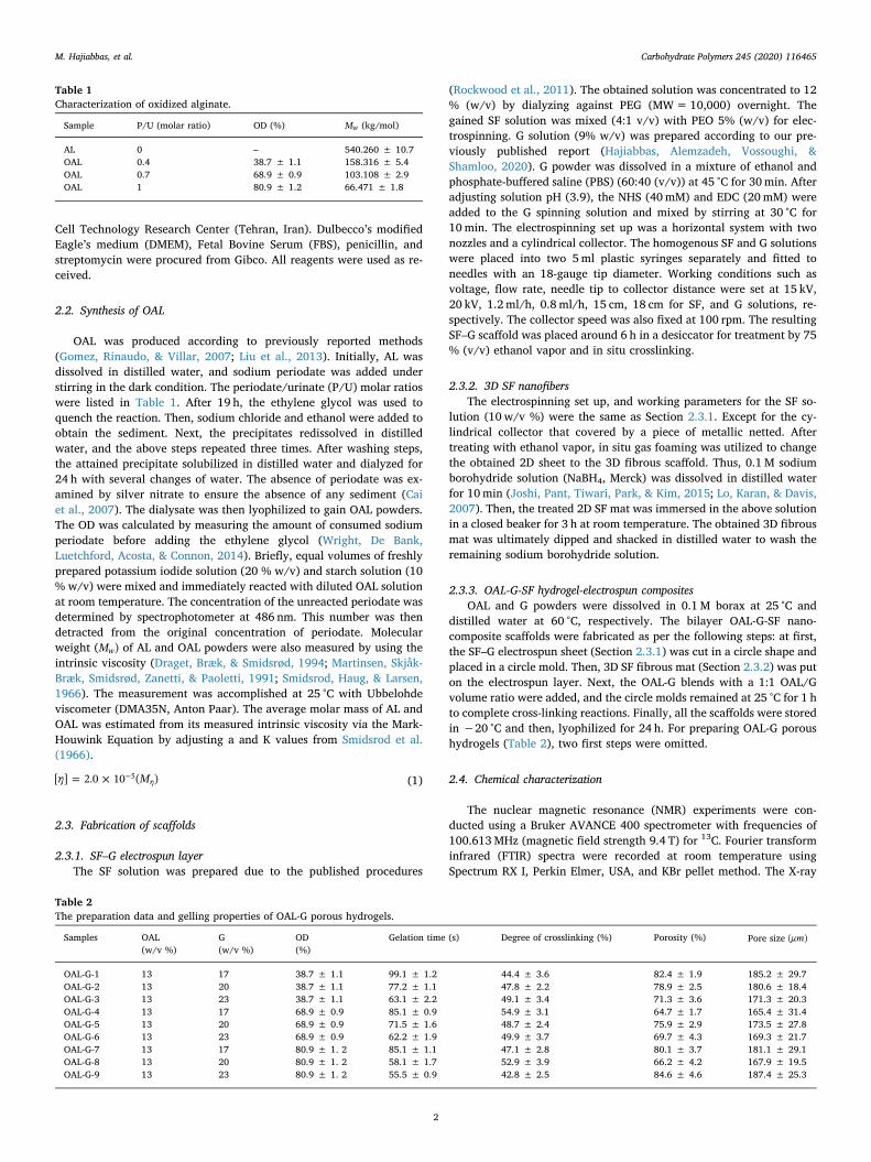
Table 1Characterization of oxidized alginate.
Sample P/U (molar ratio) OD (%) Mw (kg/mol)
AL 0 – 540.260 ± 10.7OAL 0.4 38.7 ± 1.1 158.316 ± 5.4OAL 0.7 68.9 ± 0.9 103.108 ± 2.9OAL 1 80.9 ± 1.2 66.471 ± 1.8
Table 2The preparation data and gelling properties of OAL-G porous hydrogels.
Samples OAL(w/v %)
G(w/v %)
OD(%)
Gelation time (s) Degree of crosslinking (%) Porosity (%) Pore size μm( )
OAL-G-1 13 17 38.7 ± 1.1 99.1 ± 1.2 44.4 ± 3.6 82.4 ± 1.9 185.2 ± 29.7OAL-G-2 13 20 38.7 ± 1.1 77.2 ± 1.1 47.8 ± 2.2 78.9 ± 2.5 180.6 ± 18.4OAL-G-3 13 23 38.7 ± 1.1 63.1 ± 2.2 49.1 ± 3.4 71.3 ± 3.6 171.3 ± 20.3OAL-G-4 13 17 68.9 ± 0.9 85.1 ± 0.9 54.9 ± 3.1 64.7 ± 1.7 165.4 ± 31.4OAL-G-5 13 20 68.9 ± 0.9 71.5 ± 1.6 48.7 ± 2.4 75.9 ± 2.9 173.5 ± 27.8OAL-G-6 13 23 68.9 ± 0.9 62.2 ± 1.9 49.9 ± 3.7 69.7 ± 4.3 169.3 ± 21.7OAL-G-7 13 17 80.9 ± 1. 2 85.1 ± 1.1 47.1 ± 2.8 80.1 ± 3.7 181.1 ± 29.1OAL-G-8 13 20 80.9 ± 1. 2 58.1 ± 1.7 52.9 ± 3.9 66.2 ± 4.2 167.9 ± 19.5OAL-G-9 13 23 80.9 ± 1. 2 55.5 ± 0.9 42.8 ± 2.5 84.6 ± 4.6 187.4 ± 25.3
M. Hajiabbas, et al. Carbohydrate Polymers 245 (2020) 116465
2

diffraction (XRD) data were determined with an X-ray diffractometer(X'Pert PRO MPD, Panalytical, Netherlands) equipped by Ni-filteredCuKα radiation. Diffraction patterns were collected in the range of5°–60° with a speed of 0.02°/s at room temperature. The degree ofcrosslinking in prepared scaffolds was measured by ninhydrin assay(Kishan et al., 2015; Sarker, Papageorgiou et al., 2014). The samples(0.5 g) were heated with a 2 % (w/v) ninhydrin solution at 100 °C for20min. The optical absorbance of the resulting solution was recorded at570 nm by ELIZA reader, biotech, USA. The degree of crosslinking wascalculated via Eq. (2):
= − ×Degree of crosslinking A A(%) (1 ( / )) 100c u (2)
Ac and Au represent the absorbance of crosslinked and uncrosslinkedscaffolds, respectively.
2.5. Thermogravimetric analysis (TGA)
TGA analysis of the starting materials and prepared scaffolds werecarried out by using STAPT 1600 (Linseis, Germany). Samples (10mg)in an aluminum specimen box heated under nitrogen injection with aflow rate of 20ml/min at a heating rate of 10 °C/min.
2.6. Physical characterization
Herein, gelation time is an essential property of polymer blends tofabricate nanocomposite scaffold. In this regard, OAL in 0.1M borax(pH 9.4) was mixed with G aqueous solution under magnetic stirring atroom temperature. The gelation time was recorded as the required timefor the stir bar to stop (Cai et al., 2007) The morphological structure ofthe prepared scaffolds was observed under the scanning electron mi-croscope (SEM) using the AIS2100 series model from Seron TechnologyCompany with an acceleration voltage of 30 kV. Before the imagingprocess, samples were sputter-coated with gold and imaged in theSecondary Electron Image (SEI). The porosity of OAL-G and OAL-G-SFscaffolds was examined through a liquid displacement method (Hanet al., 2013). Each dry sample was dipped in a specific volume (V1) ofethanol in a graduated cylinder for 10min. The total volume of ethanoland the immersed sample was registered V2. The ethanol-impregnatedsample was then removed to obtain the V3value as the residual ethanolvolume. Sample porosity was then computed through Eq. (3):
= − − ×Porosity V V V V(%) [( )/( )] 1001 3 2 3 (3)
For swelling ratio (Qm) and water uptake measurements, a piece of thesamples (W0) were dipped in a small beaker containing PBS solution(37 °C, 50ml) for 24 h. Next, a paper filter was used for absorbing thewater on the surface, and the wet weight was then obtained (W1). TheQm and water uptake were calculated as per the following Equations:
= − ×Q W W W(%) ( )/ 100m 1 0 0 (4)
= − ×Water uptake W W W(%) ( )/ 1001 0 1 (5)
For the moisture retention analysis, the above samples after 24 himmersing in PBS weighed precisely (W0). Next, they were placed in anincubator (37 °C) and weighed every other 30min (Wt). The moistureretention was computed by Eq. (6) (Balakrishnan, Mohanty,Umashankar, & Jayakrishnan, 2005):
= ×Remaining weight W W(%) ( / ) 100t 0 (6)
The rates of degradation were determined during four weeks ofincubation. The prepared scaffolds were placed in closed plates con-taining PBS solution (pH 7.4) and incubated at 37 °C. Then at specifictimes, the remaining weight of the samples was calculated via Eq. (7):
= ×Remaining weight W W(%) ( / ) 100f i (7)
Wi stands for the initial weight of dry scaffolds before exposure to PBS,and Wf presents the final weight of the same samples after washing
three times with ultrapure water and freeze drying.
2.7. Mechanical characterization
Mechanical characterization was performed by administering thetensile test load (STM‐20, SANTAM, Iran) to the porous samples in wetconditions. A crosshead speed of 1mm/min was applied for all of thetested specimens.
2.8. Cell-scaffold interaction
The AMSCs were cultured in DMEM medium containing 10 % FBSand 1% penicillin/streptomycin at 37 °C. The prepared scaffolds (1 cmdiameter) were sterilized using both 70 % ethanol filtered through a0.22‐micron filter and UV radiation. Next, they were incubated in thecell culture media overnight to ensure there is no microbial con-tamination. After that, AMSCs were seeded at a density of 300,000cells/well on each sample. The proliferation of seeded AMSCs on bothkinds of composite scaffolds was determined by MTT assay (Ciapetti,Cenni, Pratelli, & Pizzoferrato, 1993). In this regard, after 1, 3, and 7culture days, the medium was removed, and the seeded samples wereincubated in a mixture of serum‐free medium and MTT reagent for3.5 h. Then, dimethyl sulfoxide, DMSO (Merck), was added to the re-moved samples, and the absorbance was documented at 570 nm usingELISA plate reader (biotech, USA). For studying cell adhesion andmorphology via SEM images, after seven culture days, the samples werefixed by 2.5 % glutaraldehyde solution for 2 h and dehydrated via in-cubation for 10min in graded ethanol solutions. Hematoxylin and eosin(H&E) staining were also performed to evaluate cell distribution andinfiltration within the nanocomposite scaffold. The samples fixed in 10% formaldehyde/4% paraformaldehyde for 30min. They were thendehydrated by dipping into graded series of ethanol, transferred toxylol, and embedded in paraffin. Finally, 5 μm thick cross-sections werestained with H&E and visualized under phase-contrast microscopy. Forfurther evaluation of cell attachment, distribution, and infiltration, thenucleus staining of the cells was implemented using 4′, 6‐diamidi-no‐2‐phenylindole, DAPI (Sigma). Seeded samples were fixed using 4%paraformaldehyde, then stained with DAPI solution and imaged usingfluorescence microscopy (Nikon TE2000-S).
2.9. Statistical analysis
Each experiment was done three times, and all obtained data arepresented as mean ± standard deviation (SD). The statistical analysiswas carried out by SPSS software and t-test. P-values of less than 0.05was regarded as statistically significant.
3. Results and discussion
3.1. Synthesis of OAL
As shown in Table 1, OD and Mw of the OAL is dependent on the P/Umolar ratios, which is in agreement with other reports elsewhere(Balakrishnan and Jayakrishnan, 2005; Cai et al., 2007; Gao, Liu, Chen,& Zhang, 2009). As indicated, rising in the amount of sodium periodateleads to an increase in OD but a reduction in Mw. This decrease is re-lated to the depolymerization of AL in the oxidation reaction (Emami,Ehsani, Zandi, & Foudazi, 2018; Laurienzo, Malinconico, Motta, &Vicinanza, 2005) that enhanced the solubility of OAL.
3.2. Chemical characterization
NMR spectroscopy was employed to confirm the formation of thealdehyde group in OAL. Fig. 1(a) indicates the identified peaks signifiedto the carbon spectra of mannuronate (M) and guluronate (G) units inAL and OAL structure (Salomonsen, Jensen, Larsen, Steuernagel, &
M. Hajiabbas, et al. Carbohydrate Polymers 245 (2020) 116465
3
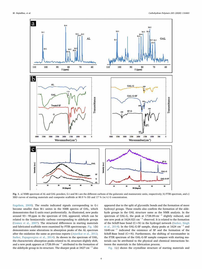
Engelsen, 2009). The results indicated signals corresponding to G-ibecome smaller than M-i unites in the NMR spectra of OAL, whichdemonstrates that G units react preferentially. As illustrated, new peaksaround 93−95 ppm in the spectrum of OAL appeared, which can berelated to the hemiacetalic carbons corresponding to aldehyde groups(Gomez et al., 2007). The structural differences in starting materialsand fabricated scaffolds were examined by FTIR spectroscopy. Fig. 1(b)demonstrates some alterations in absorption peaks of the AL spectrumafter the oxidation the same as previous reports (Jejurikar et al., 2012;Sarker, Papageorgiou et al., 2014). As shown in the spectrum of OAL,the characteristic absorption peaks related to AL structure slightly shift,and a new peak appears at 1728.09 cm−1 attributed to the formation ofthe aldehyde group in its structure. The sharper peak at 3427 cm−1 also
appeared due to the split of glycosidic bonds and the formation of morehydroxyl groups. These results also confirm the formation of the alde-hyde groups in the OAL structure same as the NMR analysis. In thespectrum of OAL-G, the peak at 1728.09 cm−1 slightly reduced, andone new peak at 1624.021 cm−1 observed. It is related to the formationof the Schiff-base bond (C]N) in the hydrogel network (Sarker, Singhet al., 2014). In the OAL-G-SF sample, sharp peaks at 1624 cm−1 and1640 cm−1 indicated the existence of SF and the formation of theSchiff-Base bond (C]N). Furthermore, the shifting of wavenumber inthe FTIR spectrum of the OAL-G-SF sample compare with starting ma-terials can be attributed to the physical and chemical interactions be-tween the materials in the fabrication process.
Fig. 1(c) shows the crystalline structure of starting materials and
Fig. 1. a) NMR spectrum of AL and OAL powders, G-i and M-i are the different carbons of the guluronic and mannuronic units, respectively; b) FTIR spectrum, and c)XRD curves of starting materials and composite scaffolds at 80.9 % OD and 17 % (w/v) G concentration.
M. Hajiabbas, et al. Carbohydrate Polymers 245 (2020) 116465
4

prepared scaffolds, which evaluated by XRD analysis. As illustrated,there are two peaks around 14.5° and 22.9° in the spectrum of AL.While, in the XRD pattern of OAL, two sharp peaks at 32.1° and 44.9°were detected. The spectrum of G exhibits one broad peak around 20°and a small one at 7.8° due to its high amorphous content and its triplehelical crystalline structure, respectively (Peña, De La Caba, Eceiza,Ruseckaite, & Mondragon, 2010). In the OAL-G sample, the strong in-teraction between OAL and G leads to the declining of the G char-acteristic peaks around 20° (Sarker, Papageorgiou et al., 2014). How-ever, in the spectrum of OAL-G-SF, two new peaks at 24.1° and 20.5°were observed. As displayed, it can be signified to the existence of SF,SF–G, and the β-sheet formation in the OAL-G-SF structure (Kim, Park,Kim, Wada, & Kaplan, 2005). The degree of cross-linking for the OAL-Gand OAL-G-SF composites are listed in Tables 2 and 3. Both OD and Gconcentration was found to be important in the degree of crosslinkingthe same as other reports (Balakrishnan and Jayakrishnan, 2005;Boanini et al., 2010). However, the results do not exhibit a clear trendas a function of OD or G concentration. It means that the deformation ofthe utilized polymers, Mw of the OAL, and the length of its polymerchain also have some complicated effects on the degree of crosslinkingin OAL-G and OAL-G-SF scaffolds.
3.3. Thermal stability
TGA analysis was employed to show the thermal stability of thesamples due to the remaining weight versus temperature.
The TGA curves of the applied materials and prepared compositesare exhibited in Fig. 2. As illustrated, OAL decomposed in lower tem-peratures compared to the AL degradation. It can be associated with theexistence of the ring-opened and the degraded AL chains (Ku, Ahn,Song, Yang, & Kim, 2014), which influence on OAL thermal stability.Moreover, it was found that the formation of the crosslinked network inthe OAL-G and OAL-G-SF composites leads to less thermal stability andmore weight loss compared to pure OAL, G, and SF polymers. While
OAL-G-SF composite had more thermal stability in T < 300 °C com-pared to the OAL-G sample. The obtained results are similar to thoseprevious reports about OAL-G and other composite biopolymers withSchiff-base reaction (Chen et al., 2012; Sarker, Papageorgiou et al.,2014).
Table 3The preparation data and properties of OAL-G-SF porous nanocomposites.
sample OAL(w/v %)
G(w/v %)
OD(%)
Degree of crosslinking (%) Porosity (%) Pore size μm( )
OAL-G-SF-1 13 17 38.7 ± 1.06 45.1 ± 2.6 89.2 ± 3.1 446.57 ± 68.9OAL-G-SF-2 13 20 38.7 ± 1.06 49.9 ± 3.1 85.7 ± 2.8 451.24 ± 74.5OAL-G-SF-3 13 23 38.7 ± 1.06 57.3 ± 2.9 74.1 ± 2.6 387.31 ± 89.4OAL-G-SF-4 13 17 68.9 ± 0.98 61.3 ± 3.6 68.6 ± 3.7 380.91 ± 90.3OAL-G-SF-5 13 20 68.9 ± 0.98 53.8 ± 3.8 79.9 ± 2.6 410.24 ± 93.5OAL-G-SF-6 13 23 68.9 ± 0.98 54.6 ± 2.7 77.1 ± 2.7 405.92 ± 88.3OAL-G-SF-7 13 17 80.9 ± 1.02 53.1 ± 4.1 80.9 ± 3.1 412.58 ± 86.2OAL-G-SF-8 13 20 80.9 ± 1.02 53.4 ± 3.6 80.3 ± 2.9 413.28 ± 79.3OAL-G-SF-9 13 23 80.9 ± 1.02 55.3 ± 3.2 76.6 ± 2.5 391.31 ± 90.2
Fig. 2. TGA curves of the starting materials and composite scaffolds at 80.9 %OD and 17 % (w/v) G concentration.
Fig. 3. The structural morphology of porous hydrogel, 3D SF electrospun, andporous bilayer nanocomposite at 80.9 % OD and 17 % (w/v) G concentration.
M. Hajiabbas, et al. Carbohydrate Polymers 245 (2020) 116465
5

3.4. Physical characterization
Table 2 shows the gelling time of OAL-G blends with variousamounts of OD and G concentrations. As displayed, the more OD re-sulted in, the faster reaction of OAL and shorter gelation time of OAL-Gcomposites. As shown, increasing G content also leads to a decrease inthe gelation time. It can be related to the higher amount of free aminegroups or the rapid physical crosslinking of G polymers in higher con-centrations (Balakrishnan and Jayakrishnan, 2005; Sarker,Papageorgiou et al., 2014). As illustrated in Fig. 3, this fabricationmethod and polymers composition is a suitable candidate to mimic the3D extracellular structure. The porosity and pore size of the preparedscaffolds are also listed in Tables 2 and 3. As shown, all samples hadappropriate porosity and pore size for tissue engineering applications.The data demonstrated that utilized materials and fabrication methodshave remarkable effects on the distribution of pore size in the scaffoldstructure. It can be attributed to the in situ gas foaming process andheterogeneous spreading of hydrogen gas bubbles inside the nanofibersand hydrogel network. Fig. 4 shows the comparative study of differentphysical properties of OAL-G and OAL-G-SF scaffolds. As illustrated, theQmsame as the degree of crosslinking and gelation time is dependent onsimilar complicated factors. The results indicated that swelling was
relatively high for both kinds of composites compare with other reportselsewhere (Baniasadi, Mashayekhan, Fadaoddini, &Haghirsharifzamini, 2016; Gao et al., 2009; Ku et al., 2014). However,for OAL-G-SF nanocomposites, a reduction in Qm was detected com-pared to OAL-G porous hydrogels. It might be related to the highercrosslinking density in nanocomposite scaffolds, which leads to a morerobust network and the lower Qm. Also, all kinds of scaffolds indicatedsuitable fluid uptake ability (Fig. 4(b)). Nonetheless, there are somedifferences in water holding capacity of OAL-G-SF nanocomposites andOAL-G porous hydrogels. This variety might be due to the quality anddegree of crosslinking that alters the conformation of polysaccharideand proteins, which could further affect their water uptake properties(Balakrishnan et al., 2005). The illustration results in Fig. 4(c) alsoindicated that an increase in OD raised the water evaporation rate ofOAL-G samples, which might be related to the oxidation reaction thatdecreased the moisture retention of the AL chain. While, for OAL-G-SFcomposites, reducing G concentration leads to an increase in waterevaporation rate.
Fig. 4(d) exhibits the degradation rate of the OAL-G and OAL-G-SFscaffolds during four weeks of incubation. As displayed, scaffoldstructure, the chain entanglement, the existence of some long polymerchains, and the maintenance of some crosslinking, which could defer
Fig. 4. The Swelling ratio (a), Water uptake (b), Moisture retention (c), and Degradability (d) of OAL-G and OAL-G-SF porous hydrogels at different amount of ODand G concentrations.
M. Hajiabbas, et al. Carbohydrate Polymers 245 (2020) 116465
6
the ability of polymer strings to diffuse out of the sample construction,caused some variation in degradation rate.
3.5. Mechanical characterization
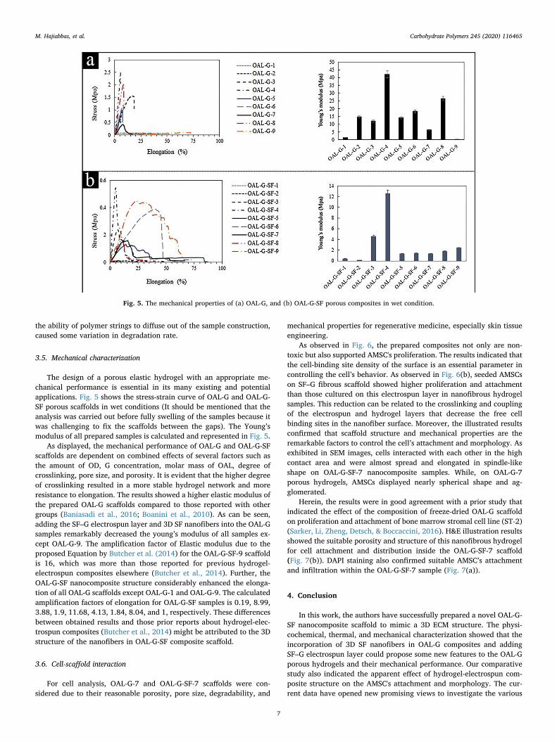
The design of a porous elastic hydrogel with an appropriate me-chanical performance is essential in its many existing and potentialapplications. Fig. 5 shows the stress-strain curve of OAL-G and OAL-G-SF porous scaffolds in wet conditions (It should be mentioned that theanalysis was carried out before fully swelling of the samples because itwas challenging to fix the scaffolds between the gaps). The Young’smodulus of all prepared samples is calculated and represented in Fig. 5.
As displayed, the mechanical performance of OAL-G and OAL-G-SFscaffolds are dependent on combined effects of several factors such asthe amount of OD, G concentration, molar mass of OAL, degree ofcrosslinking, pore size, and porosity. It is evident that the higher degreeof crosslinking resulted in a more stable hydrogel network and moreresistance to elongation. The results showed a higher elastic modulus ofthe prepared OAL-G scaffolds compared to those reported with othergroups (Baniasadi et al., 2016; Boanini et al., 2010). As can be seen,adding the SF–G electrospun layer and 3D SF nanofibers into the OAL-Gsamples remarkably decreased the young’s modulus of all samples ex-cept OAL-G-9. The amplification factor of Elastic modulus due to theproposed Equation by Butcher et al. (2014) for the OAL-G-SF-9 scaffoldis 16, which was more than those reported for previous hydrogel-electrospun composites elsewhere (Butcher et al., 2014). Further, theOAL-G-SF nanocomposite structure considerably enhanced the elonga-tion of all OAL-G scaffolds except OAL-G-1 and OAL-G-9. The calculatedamplification factors of elongation for OAL-G-SF samples is 0.19, 8.99,3.88, 1.9, 11.68, 4.13, 1.84, 8.04, and 1, respectively. These differencesbetween obtained results and those prior reports about hydrogel-elec-trospun composites (Butcher et al., 2014) might be attributed to the 3Dstructure of the nanofibers in OAL-G-SF composite scaffold.
3.6. Cell-scaffold interaction
For cell analysis, OAL-G-7 and OAL-G-SF-7 scaffolds were con-sidered due to their reasonable porosity, pore size, degradability, and
mechanical properties for regenerative medicine, especially skin tissueengineering.
As observed in Fig. 6, the prepared composites not only are non-toxic but also supported AMSC's proliferation. The results indicated thatthe cell-binding site density of the surface is an essential parameter incontrolling the cell’s behavior. As observed in Fig. 6(b), seeded AMSCson SF–G fibrous scaffold showed higher proliferation and attachmentthan those cultured on this electrospun layer in nanofibrous hydrogelsamples. This reduction can be related to the crosslinking and couplingof the electrospun and hydrogel layers that decrease the free cellbinding sites in the nanofiber surface. Moreover, the illustrated resultsconfirmed that scaffold structure and mechanical properties are theremarkable factors to control the cell’s attachment and morphology. Asexhibited in SEM images, cells interacted with each other in the highcontact area and were almost spread and elongated in spindle-likeshape on OAL-G-SF-7 nanocomposite samples. While, on OAL-G-7porous hydrogels, AMSCs displayed nearly spherical shape and ag-glomerated.
Herein, the results were in good agreement with a prior study thatindicated the effect of the composition of freeze-dried OAL-G scaffoldon proliferation and attachment of bone marrow stromal cell line (ST-2)(Sarker, Li, Zheng, Detsch, & Boccaccini, 2016). H&E illustration resultsshowed the suitable porosity and structure of this nanofibrous hydrogelfor cell attachment and distribution inside the OAL-G-SF-7 scaffold(Fig. 7(b)). DAPI staining also confirmed suitable AMSC’s attachmentand infiltration within the OAL-G-SF-7 sample (Fig. 7(a)).
4. Conclusion
In this work, the authors have successfully prepared a novel OAL-G-SF nanocomposite scaffold to mimic a 3D ECM structure. The physi-cochemical, thermal, and mechanical characterization showed that theincorporation of 3D SF nanofibers in OAL-G composites and addingSF–G electrospun layer could propose some new features to the OAL-Gporous hydrogels and their mechanical performance. Our comparativestudy also indicated the apparent effect of hydrogel-electrospun com-posite structure on the AMSC's attachment and morphology. The cur-rent data have opened new promising views to investigate the various
Fig. 5. The mechanical properties of (a) OAL-G, and (b) OAL-G-SF porous composites in wet condition.
M. Hajiabbas, et al. Carbohydrate Polymers 245 (2020) 116465
7

Fig. 6. (a) SEM images of AMSC’s morphology on the surface of the OAL-G-7 and OAL-G-SF-7 porous composites after seven days of cell culture, (b) Cell viability andproliferation on composite scaffolds.
Fig. 7. The representing images of (a) DAPI and (b) H&E staining of seeded AMSCs within the OAL-G-SF-7 scaffold after seven days of cell culture.
M. Hajiabbas, et al. Carbohydrate Polymers 245 (2020) 116465
8

application of this novel nanofibrous hydrogel composite in biomedicalengineering as a scaffold and a drug delivery system.
Funding
This research did not receive any specific grant from fundingagencies in the public commercial or not-for-profit sectors.
CRediT authorship contribution statement
Maryam Hajiabbas: Investigation, Methodology, Formal analysis,Writing - original draft, Writing - review & editing. Iran Alemzadeh:Supervision, Writing - review & editing. Manouchehr Vossoughi:Supervision, Writing - review & editing.
Declaration of Competing Interest
None.
Acknowledgments
The authors gratefully acknowledge the Institute of Biotechnologyand Environment, Sharif University of Technology, the Stem CellTechnology Research Centre, and the Iranian BiotechnologyDevelopment Council for their cooperation and experimental equip-ment support during this study.
References
Balakrishnan, B., & Jayakrishnan, A. (2005). Self-cross-linking biopolymers as injectablein situ forming biodegradable scaffolds. Biomaterials, 26(18), 3941–3951.
Balakrishnan, B., Mohanty, M., Umashankar, P. R., & Jayakrishnan, A. (2005). Evaluationof an in situ forming hydrogel wound dressing based on oxidized alginate and gelatin.Biomaterials, 26(32), 6335–6342.
Baniasadi, H., Mashayekhan, S., Fadaoddini, S., & Haghirsharifzamini, Y. (2016). Design,fabrication and characterization of oxidized alginate–gelatin hydrogels for muscletissue engineering applications. Journal of Biomaterials Applications, 31(1), 152–161.
Boanini, E., Rubini, K., Panzavolta, S., & Bigi, A. (2010). Chemico-physical character-ization of gelatin films modified with oxidized alginate. Acta Biomaterialia, 6(2),383–388.
Boontheekul, T., Kong, H. J., & Mooney, D. J. (2005). Controlling alginate gel degradationutilizing partial oxidation and bimodal molecular weight distribution. Biomaterials,26(15), 2455–2465.
Bosworth, L. A., Turner, L. A., & Cartmell, S. H. (2013). State of the art compositescomprising electrospun fibres coupled with hydrogels: A review. NanomedicineNanotechnology Biology and Medicine, 9(3), 322–335.
Butcher, A. L., Offeddu, G. S., & Oyen, M. L. (2014). Nanofibrous hydrogel composites asmechanically robust tissue engineering scaffolds. Trends in Biotechnology, 32(11),564–570.
Cai, K., Zhang, J., Deng, L., Yang, L., Hu, Y., Chen, C., ... Wang, L. (2007). Physical andbiological properties of a novel hydrogel composite based on oxidized alginate, ge-latin and tricalcium phosphate for bone tissue engineering. Advanced EngineeringMaterials, 9(12), 1082–1088.
Chen, F., Tian, M., Zhang, D., Wang, J., Wang, Q., Yu, X., ... Wan, C. (2012). Preparationand characterization of oxidized alginate covalently cross-linked galactosylatedchitosan scaffold for liver tissue engineering. Materials Science and Engineering C,32(2), 310–320.
Ciapetti, G., Cenni, E., Pratelli, L., & Pizzoferrato, A. (1993). In vitro evaluation of cell/biomaterial interaction by MTT assay. Biomaterials, 14(5), 359–364.
Draget, K. I., Bræk, G. S., & Smidsrød, O. (1994). Alginic acid gels: the effect of alginatechemical composition and molecular weight. Carbohydrate Polymers, 25(1), 31–38.
Emami, Z., Ehsani, M., Zandi, M., & Foudazi, R. (2018). Controlling alginate oxidationconditions for making alginate-gelatin hydrogels. Carbohydrate Polymers, 198,509–517.
Gao, C., Liu, M., Chen, J., & Zhang, X. (2009). Preparation and controlled degradation ofoxidized sodium alginate hydrogel. Polymer Degradation and Stability, 94(9),1405–1410.
Gomez, C. G., Rinaudo, M., & Villar, M. A. (2007). Oxidation of sodium alginate andcharacterization of the oxidized derivatives. Carbohydrate Polymers, 67(3), 296–304.
Hajiabbas, M., Alemzadeh, I., Vossoughi, M., & Shamloo, A. (2020). In-situ crosslinking ofelectrospun gelatin-carbodiimide nanofibers: fabrication, characterization, and
modeling of solution parameters. Chemical Engineering Communications, 1–17. https://doi.org/10.1080/00986445.2020.1725491.
Han, N., Bradley, P. A., Johnson, J., Parikh, K. S., Hissong, A., Calhoun, M. A., ... Winter,J. O. (2013). Effects of hydrophobicity and mat thickness on release from hydrogel-electrospun fiber mat composites. Journal of Biomaterials Science Polymer Edition,24(17), 2018–2030.
Jejurikar, A., Seow, X. T., Lawrie, G., Martin, D., Jayakrishnan, A., & Grøndahl, L. (2012).Degradable alginate hydrogels crosslinked by the macromolecular crosslinker algi-nate dialdehyde. Journal of Materials Chemistry, 22(19), 9751–9758.
Joshi, M. K., Pant, H. R., Tiwari, A. P., Park, C. H., & Kim, C. S. (2015). Multi-layeredmacroporous three-dimensional nanofibrous scaffold via a novel gas foaming tech-nique. Chemical Engineering Journal, 275, 79–88.
Kim, U. J., Park, J., Kim, H. J., Wada, M., & Kaplan, D. L. (2005). Three-dimensionalaqueous-derived biomaterial scaffolds from silk fibroin. Biomaterials, 26(15),2775–2785.
Kim, T. G., Shin, H., & Lim, D. W. (2012). Biomimetic scaffolds for tissue engineering.Advanced Functional Materials, 22(12), 2446–2468.
Kishan, A. P., Nezarati, R. M., Radzicki, C. M., Renfro, A. L., Robinson, J. L., Whitely, M.E., ... Cosgriff-Hernandez, E. M. (2015). In situ crosslinking of electrospun gelatin forimproved fiber morphology retention and tunable degradation. Journal of MaterialsChemistry B, 3(40), 7930–7938.
Kong, H. J., Kaigler, D., Kim, K., & Mooney, D. J. (2004). Controlling rigidity and de-gradation of alginate hydrogels via molecular weight distribution. Biomacromolecules,5(5), 1720–1727.
Ku, M. K., Ahn, Y., Song, Y., Yang, Y. H., & Kim, H. (2014). Effect of oxidized alginate onits electrospinnability. Fibers and Polymers, 15(9), 1835–1841.
Laurienzo, P., Malinconico, M., Motta, A., & Vicinanza, A. (2005). Synthesis and char-acterization of a novel alginate–poly (ethylene glycol) graft copolymer. CarbohydratePolymers, 62(3), 274–282.
Liao, H., Zhang, H., & Chen, W. (2009). Differential physical, rheological, and biologicalproperties of rapid in situ gelable hydrogels composed of oxidized alginate and ge-latin derived from marine or porcine sources. Journal of Materials Science Materials inMedicine, 20(6), 1263–1271.
Liu, X., Peng, W., Wang, Y., Zhu, M., Sun, T., Peng, Q., ... Wang, J. (2013). Synthesis of anRGD-grafted oxidized sodium alginate–N-succinyl chitosan hydrogel and an in vitrostudy of endothelial and osteogenic differentiation. Journal of Materials Chemistry B,1(35), 4484–4492.
Lo, C. T. F., Karan, K., & Davis, B. R. (2007). Kinetic studies of reaction between sodiumborohydride and methanol, water, and their mixtures. Industrial & EngineeringChemistry Research, 46(17), 5478–5484.
Martinsen, A., Skjåk-Bræk, G., Smidsrød, O., Zanetti, F., & Paoletti, S. (1991). Comparisonof different methods for determination of molecular weight and molecular weightdistribution of alginates. Carbohydrate Polymers, 15(2), 171–193.
Peña, C., De La Caba, K. O. R. O., Eceiza, A., Ruseckaite, R., & Mondragon, I. (2010).Enhancing water repellence and mechanical properties of gelatin films by tanninaddition. Bioresource Technology, 101(17), 6836–6842.
Rockwood, D. N., Preda, R. C., Yücel, T., Wang, X., Lovett, M. L., & Kaplan, D. L. (2011).Materials fabrication from Bombyx mori silk fibroin. Nature Protocols, 6(10), 1612.
Sahoo, N. G., Pan, Y. Z., Li, L., & He, C. B. (2013). Nanocomposites for bone tissue re-generation. Nanomedicine, 8(4), 639–653.
Salomonsen, T., Jensen, H. M., Larsen, F. H., Steuernagel, S., & Engelsen, S. B. (2009).Direct quantification of M/G ratio from 13C CP-MAS NMR spectra of alginate pow-ders by multivariate curve resolution. Carbohydrate Research, 344(15), 2014–2022.
Sarker, B., Li, W., Zheng, K., Detsch, R., & Boccaccini, A. R. (2016). Designing porousbone tissue engineering scaffolds with enhanced mechanical properties from com-posite hydrogels composed of modified alginate, gelatin, and bioactive glass. ACSBiomaterials Science & Engineering, 2(12), 2240–2254.
Sarker, B., Papageorgiou, D. G., Silva, R., Zehnder, T., Gul-E-Noor, F., Bertmer, M., ...Boccaccini, A. R. (2014). Fabrication of alginate–gelatin crosslinked hydrogel mi-crocapsules and evaluation of the microstructure and physico-chemical properties.Journal of Materials Chemistry B, 2(11), 1470–1482.
Sarker, B., Singh, R., Silva, R., Roether, J. A., Kaschta, J., Detsch, R., ... Boccaccini, A. R.(2014). Evaluation of fibroblasts adhesion and proliferation on alginate-gelatincrosslinked hydrogel. PloS One, 9(9).
Slaughter, B. V., Khurshid, S. S., Fisher, O. Z., Khademhosseini, A., & Peppas, N. A.(2009). Hydrogels in regenerative medicine. Advanced Materials, 21(32–33),3307–3329.
Smidsrod, O., Haug, A. R. N. E., & Larsen, B. (1966). The influence of pH on the rate ofhydrolysis of acidic polysaccharides. Acta Chemica Scandinavica, 20(4), 1026–1034.
Studart, A. R. (2013). Biological and bioinspired composites with spatially tunable het-erogeneous architectures. Advanced Functional Materials, 23(36), 4423–4436.
Wright, B., De Bank, P. A., Luetchford, K. A., Acosta, F. R., & Connon, C. J. (2014).Oxidized alginate hydrogels as niche environments for corneal epithelial cells.Journal of Biomedical Materials Research Part A, 102(10), 3393–3400.
Xie, J., Li, X., & Xia, Y. (2008). Putting electrospun nanofibers to work for biomedicalresearch. Macromolecular Rapid Communications, 29(22), 1775–1792.
Xu, S., Deng, L., Zhang, J., Yin, L., & Dong, A. (2016). Composites of electrospun‐fibersand hydrogels: A potential solution to current challenges in biological and biomedicalfield. Journal of Biomedical Materials Research Part B: Applied Biomaterials, 104(3),640–656.
M. Hajiabbas, et al. Carbohydrate Polymers 245 (2020) 116465
9

本文献由“学霸图书馆-文献云下载”收集自网络,仅供学习交流使用。
学霸图书馆(www.xuebalib.com)是一个“整合众多图书馆数据库资源,
提供一站式文献检索和下载服务”的24 小时在线不限IP
图书馆。
图书馆致力于便利、促进学习与科研,提供最强文献下载服务。
图书馆导航:
图书馆首页 文献云下载 图书馆入口 外文数据库大全 疑难文献辅助工具